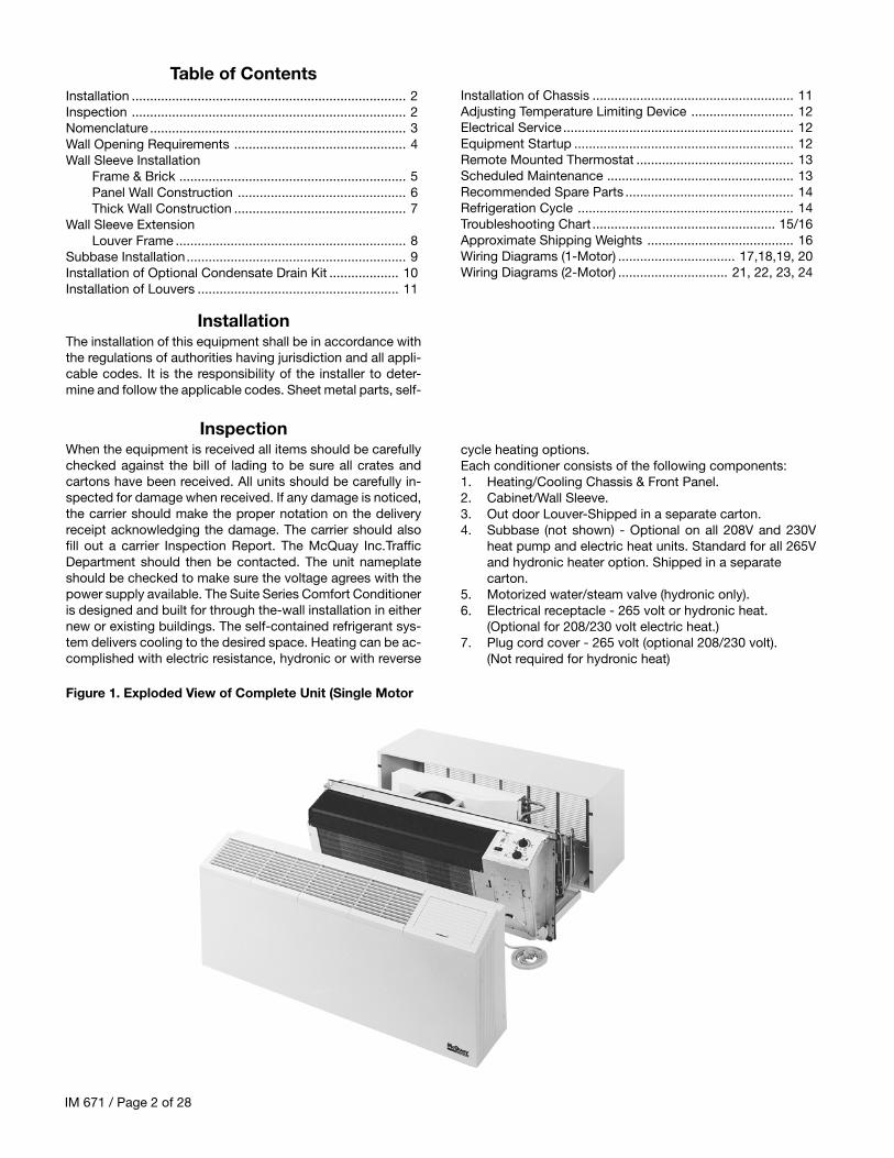
cycle heating options.Each conditioner consists of the following components:1. Heating/Cooling Chassis & Front Panel.2. Cabinet/Wall Sleeve.3. Out door Louver-Shipped in a separate carton.4. Subbase (not shown) - Optional on all 208V and 230V
heat pump and electric heat units. Standard for all 265Vand hydronic heater option. Shipped in a separatecarton.
5. Motorized water/steam valve (hydronic only).6. Electrical receptacle - 265 volt or hydronic heat.
(Optional for 208/230 volt electric heat.)7. Plug cord cover - 265 volt (optional 208/230 volt).
(Not required for hydronic heat)
When the equipment is received all items should be carefullychecked against the bill of lading to be sure all crates andcartons have been received. All units should be carefully in-spected for damage when received. If any damage is noticed,the carrier should make the proper notation on the deliveryreceipt acknowledging the damage. The carrier should alsofill out a carrier Inspection Report. The McQuay Inc.TrafficDepartment should then be contacted. The unit nameplateshould be checked to make sure the voltage agrees with thepower supply available. The Suite Series Comfort Conditioneris designed and built for through the-wall installation in eithernew or existing buildings. The self-contained refrigerant sys-tem delivers cooling to the desired space. Heating can be ac-complished with electric resistance, hydronic or with reverse
Subbase Installation............................................................ 9Installation of Optional Condensate Drain Kit ................... 10Installation of Louvers ....................................................... 11
Table of Contents
InstallationThe installation of this equipment shall be in accordance withthe regulations of authorities having jurisdiction and all appli-cable codes. It is the responsibility of the installer to deter-mine and follow the applicable codes. Sheet metal parts, self-
Inspection
Figure 1. Exploded View of Complete Unit (Single Motor
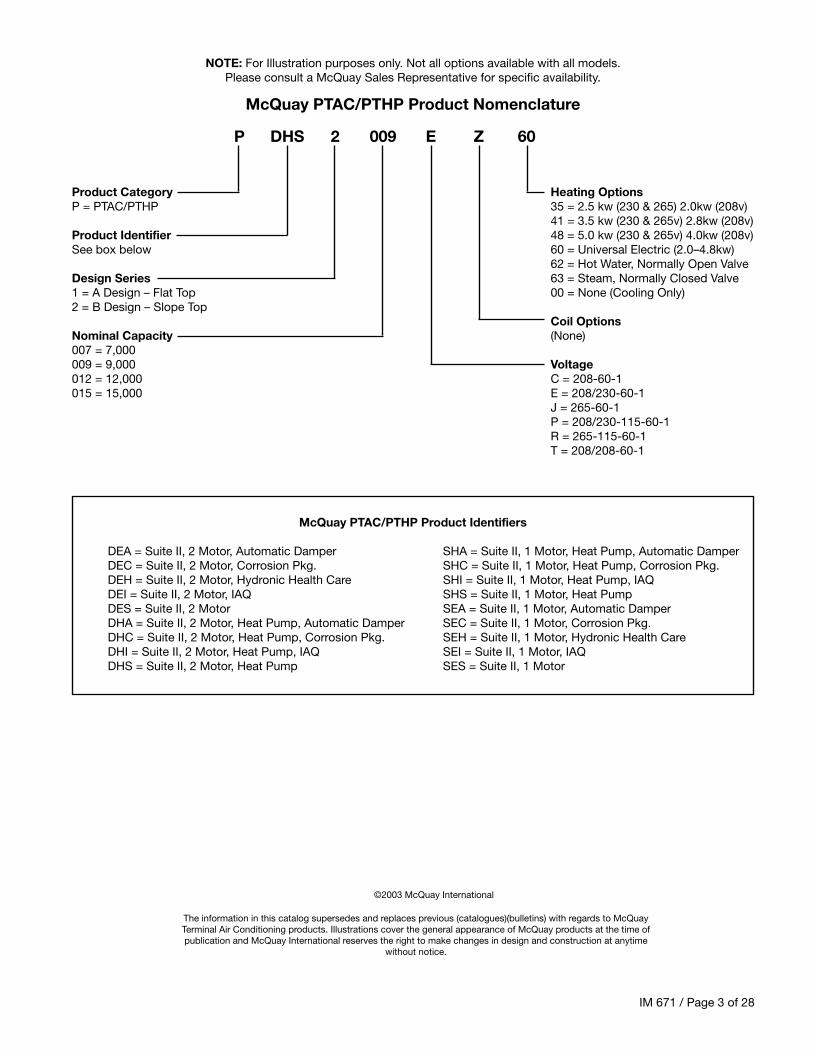
62 = Hot Water, Normally Open ValveDesign Series 63 = Steam, Normally Closed Valve1 = A Design – Flat Top 00 = None (Cooling Only)2 = B Design – Slope Top
Coil OptionsNominal Capacity (None)007 = 7,000009 = 9,000 Voltage012 = 12,000 C = 208-60-1015 = 15,000 E = 208/230-60-1
DEA = Suite II, 2 Motor, Automatic Damper SHA = Suite II, 1 Motor, Heat Pump, Automatic DamperDEC = Suite II, 2 Motor, Corrosion Pkg. SHC = Suite II, 1 Motor, Heat Pump, Corrosion Pkg.DEH = Suite II, 2 Motor, Hydronic Health Care SHI = Suite II, 1 Motor, Heat Pump, IAQDEI = Suite II, 2 Motor, IAQ SHS = Suite II, 1 Motor, Heat PumpDES = Suite II, 2 Motor SEA = Suite II, 1 Motor, Automatic DamperDHA = Suite II, 2 Motor, Heat Pump, Automatic Damper SEC = Suite II, 1 Motor, Corrosion Pkg.DHC = Suite II, 2 Motor, Heat Pump, Corrosion Pkg. SEH = Suite II, 1 Motor, Hydronic Health CareDHI = Suite II, 2 Motor, Heat Pump, IAQ SEI = Suite II, 1 Motor, IAQDHS = Suite II, 2 Motor, Heat Pump SES = Suite II, 1 Motor
NOTE: For Illustration purposes only. Not all options available with all models.Please consult a McQuay Sales Representative for specific availability.
The information in this catalog supersedes and replaces previous (catalogues)(bulletins) with regards to McQuayTerminal Air Conditioning products. Illustrations cover the general appearance of McQuay products at the time ofpublication and McQuay International reserves the right to make changes in design and construction at anytime
without notice.
IM 671 / Page 4 of 28
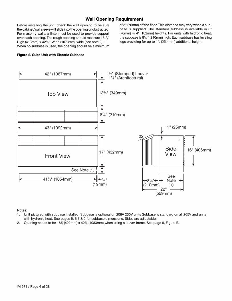
Wall Opening RequirementBefore installing the unit, check the wall opening to be surethe cabinet/wall sleeve will slide into the opening unobstructed.For masonry walls, a lintel must be used to provide supportover each opening. The rough opening should measure 161/4"High (413mm) x 421/4" Wide (1073mm) wide (see note 2).When no subbase is used, the opening should be a minimum
Notes:1. Unit pictured with subbase installed. Subbase is optional on 208V 230V units Subbase is standard on all 265V and units
with hydronic heat. See pages 5, 6 7 & 9 for subbase dimensions. Sides are adjustable.2. Opening needs to be 165⁄8 (422mm) x 425⁄8 (1083mm) when using a louver frame. See page 8, Figure B.
of 3" (76mm) off the floor. This distance may vary when a sub-base is supplied. The standard subbase is available in 3"(76mm) or 4" (102mm) heights. For units with hydronic heat,the subbase is 81/4" (210mm) high. Each subbase has levelinglegs providing for up to 1". (25.4mm) additional height.
Figure 2. Suite Unit with Electric Subbase
81⁄4" (210mm)
43" (1092mm)
42" (1067mm)
133⁄4" (349mm)Top View
411⁄2" (1054mm)
17" (432mm)Front View
3⁄4"(19mm)
3⁄8" (Stamped) Louver11⁄8" (Architectural)
See Note 1
81⁄4" (210mm)
SideView
22"(559mm)
1" (25mm)
22°
16" (406mm)
SeeNote
1
IM 671 / Page 5 of 28
A heavy-gauge, corrosion resistant cabinet/wall sleeve is provided for each unit. The cabinet/wall sleeve is either shipped in aseparate carton or shipped in a multi-pack of 15.
The standard cabinet/wall sleeve is designed to be easily in-stalled in a variety of wall constructions.Note: The center of gravity is 101⁄4" (260mm) from the rearface of the wall sleeve. The wall sleeve must be inserted intothe was at least 101⁄4" (260mm) or other support must be em-ployed.Support can be from a factory supplied subbase or from otherfield supplied materials, the wall sleeve is not intended to re-place the lintel. Recommended installation procedures are de-scribed below:1. Clean the opening of all debris that may interfere with
installation.2. If the unit is to be supplied with a subbase, refer to page
9 for installation procedure. Install subbase before install-ing cabinet/wall sleeve.
3. If the optional drain kit is to be employed refer to page 10before proceeding.
4. Place a thin pad of soft mortar on bottom of the openingand slide in the cabinet/wall sleeve. Be sure to recess thewall sleeve enough to accommodate outside louver. Thisrecess is 3⁄8" (9.5mm) for stamped louvers and 11⁄8" (32mm)for architectural louver. Louver should be flush to exteriorsurface when complete. Note: Do not recess if using theexternal drain kit - see pg. 10.
5. Level cabinet /wall sleeve in both directions and secureby anchoring with appropriate fasteners (as shown in fig-ure C page 8). A 5⁄16" (8mm) hole is provided on each side,2" (51 mm) down from the top and 2" (51 mm) in from therear of the cabinet/wall sleeve. Additional holes may berequired to firmly secure the cabinet/wall sleeve.Caution: Do not drill holes in the subbase of the cabi-net/wall sleeve. Where a subbase is used, secure wall
Wall Sleeve Installation – Frame and Brick
Note: Standard Subbase is available in 3" (76mm) or 4" (102mm) height.Leveling legs provide adjustment of 1" (25.4mm).
Figure 4. Frame & Brick with Standard Electric SubbaseFigure 6. Frame & Brick with Hydronic Subbase
Figure 5. Panel Wall Construction with Cord Connection
sleeve to subbase with clips provided.6. Caulk the cabinet/wall sleeve to the wall opening on both
inside and outside perimeter. Be careful not to plug theweep holes. Caulking should be resilient, non hardeningtype such as silicone.
Finished Flooror Carpet
133⁄4"(349mm)
16"(406mm)
3" (76mm)
17"(406mm)
Wall Receptacleby Others
CaulkPerimeter
BothIndoors &Outdoors
OutdoorLouver
Steel Lintel(by Others)
MountingScrews
byInstaller
Finished Flooror Top of Carpet
133⁄4"(349mm)
16"(406mm)
17"(406mm)
Power SupplyConnect(Alternate Entry)
CaulkPerimeter
BothIndoors &Outdoors
BeforeInstalling
Louver
OutdoorLouver
Steel Lintel (by Others)
MountingScrews
byInstaller
43⁄8"(111mm)
RoomCabinet
81⁄4"(203mm)
LevelingLeg
See Note
Wall Sleeve
Finished Flooror Carpet
16"(406mm)
17"(406mm)
CaulkPerimeter Both
Indoors & Outdoors
OutdoorLouver
Steel Lintel (by Others)
MountingScrews
byInstaller
RoomCabinet
81⁄4"(203mm)
Leveling Legs w/1"Adjustment
Hydronic Subbase
Wall Sleeve
SubbaseSide Channel
AlternateElectrical
Connections
HydronicHeating Coil
81⁄4" (203mm)
133⁄4"(349mm)
IM 671 / Page 6 of 28
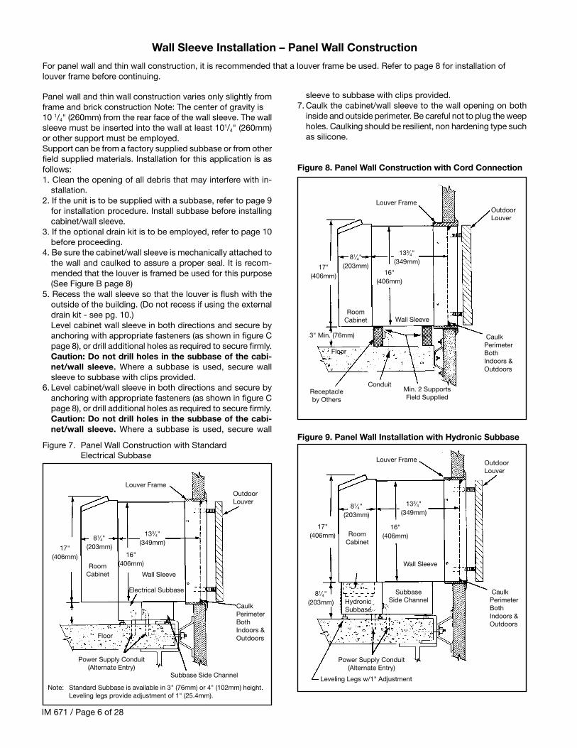
For panel wall and thin wall construction, it is recommended that a louver frame be used. Refer to page 8 for installation oflouver frame before continuing.
Panel wall and thin wall construction varies only slightly fromframe and brick construction Note: The center of gravity is10 1/4" (260mm) from the rear face of the wall sleeve. The wallsleeve must be inserted into the wall at least 101/4" (260mm)or other support must be employed.Support can be from a factory supplied subbase or from otherfield supplied materials. Installation for this application is asfollows:1. Clean the opening of all debris that may interfere with in-
stallation.2. If the unit is to be supplied with a subbase, refer to page 9
for installation procedure. Install subbase before installingcabinet/wall sleeve.
3. If the optional drain kit is to be employed, refer to page 10before proceeding.
4. Be sure the cabinet/wall sleeve is mechanically attached tothe wall and caulked to assure a proper seal. It is recom-mended that the louver is framed be used for this purpose(See Figure B page 8)
5. Recess the wall sleeve so that the louver is flush with theoutside of the building. (Do not recess if using the externaldrain kit - see pg. 10.)Level cabinet wall sleeve in both directions and secure byanchoring with appropriate fasteners (as shown in figure Cpage 8), or drill additional holes as required to secure firmly.Caution: Do not drill holes in the subbase of the cabi-net/wall sleeve. Where a subbase is used, secure wallsleeve to subbase with clips provided.
6. Level cabinet/wall sleeve in both directions and secure byanchoring with appropriate fasteners (as shown in figure Cpage 8), or drill additional holes as required to secure firmly.Caution: Do not drill holes in the subbase of the cabi-net/wall sleeve. Where a subbase is used, secure wall
Wall Sleeve Installation – Panel Wall Construction
Figure 7. Panel Wall Construction with StandardElectrical Subbase
Figure 9. Panel Wall Installation with Hydronic Subbase
Figure 8. Panel Wall Construction with Cord Connection
Note: Standard Subbase is available in 3" (76mm) or 4" (102mm) height.Leveling legs provide adjustment of 1" (25.4mm).
sleeve to subbase with clips provided.7. Caulk the cabinet/wall sleeve to the wall opening on both
inside and outside perimeter. Be careful not to plug the weepholes. Caulking should be resilient, non hardening type suchas silicone.
Floor
16"(406mm)
17"(406mm)
CaulkPerimeterBothIndoors &Outdoors
OutdoorLouver
Louver Frame
RoomCabinet
81⁄4"(203mm)
Wall Sleeve
Min. 2 SupportsField Supplied
Receptacleby Others
3" Min. (76mm)
133⁄4"(349mm)
16"(406mm)
17"(406mm)
OutdoorLouver
Louver Frame
RoomCabinet
81⁄4"(203mm)
Wall Sleeve
133⁄4"(349mm)
81⁄4"(203mm) Hydronic
Subbase
SubbaseSide Channel
CaulkPerimeterBothIndoors &Outdoors
Power Supply Conduit(Alternate Entry)
16"(406mm)
17"(406mm)
OutdoorLouver
Louver Frame
RoomCabinet
81⁄4"(203mm)
Wall Sleeve
133⁄4"(349mm)
Subbase Side Channel
CaulkPerimeterBothIndoors &Outdoors
Power Supply Conduit(Alternate Entry)
Electrical Subbase
Leveling Legs w/1" Adjustment
Floor
Conduit
IM 671 / Page 7 of 28
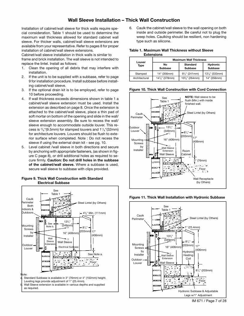
Installation of cabinet/wall sleeve for thick walls require spe-cial consideration. Table 1 should be used to determine themaximum wall thickness allowed for standard cabinet wallsleeve. For thicker walls, cabinet/wall sleeve extensions areavailable from your representative. Refer to pages 8 for properinstallation of cabinet/wall sleeve extensions.Cabinet/wall sleeve installation in thick walls is similar toframe and brick installation. The wall sleeve is not intended toreplace the lintel. Install as follows:1. Clean the opening of all debris that may interfere with
installation.2. If the unit is to be supplied with a subbase, refer to page
9 for installation procedure. Install subbase before install-ing cabinet/wall sleeve.
3. If the optional drain kit is to be employed, refer to page10 before proceeding.
4. If wall thickness exceeds dimensions shown in table 1 acabinet/wall sleeve extension must be used. Install theextension as described on page 8. Once the extension isattached to the cabinet/wall sleeve, place a thin pad ofsoft mortar on bottom of the opening and slide in the wall/sleeve extension assembly. Be sure to recess the wall/sleeve enough to accommodate outside louver. This re-cess is 3/8"(9.5mm) for stamped louvers and 11/8"(32mm)for architecture louvers. Louvers should be flush to exte-rior surface when completed. Note : Do not recess thesleeve if using the external drain kit - see pg. 10.
5. Level cabinet /wall sleeve in both directions and secureby anchoring with appropriate fasteners, (as shown in fig-ure C page 8), or drill additional holes as required to se-cure firmly. Caution: Do not drill holes in the subbaseof the cabinet/wall sleeve. Where a subbase is used,secure wall sleeve to subbase with clips provided.
Wall Sleeve Installation – Thick Wall Construction
Figure 9. Thick Wall Construction with StandardElectrical Subbase
Figure 11. Thick Wall Installation with Hydronic Subbase
Figure 10. Thick Wall Construction with Cord Connection
Note:a. Standard Subbase is available in 3" (76mm) or 4" (102mm) height.
Leveling legs provide adjustment of 1" (25.4mm).b. Wall Sleeve extension is available in various depths and supplied
as required.
Table 1. Maximum Wall Thickness without SleeveExtensions
6. Caulk the cabinet/wall sleeve to the wall opening on bothinside and outside perimeter. Be careful not to plug theweep holes. Caulking should be resilient, non hardeningtype such as silicone.
NOTE: Wall sleeve to beflush (Min.) with insidefinished wall.
Wall SleeveExtension
Wall SleeveExtension
IM 671 / Page 8 of 28
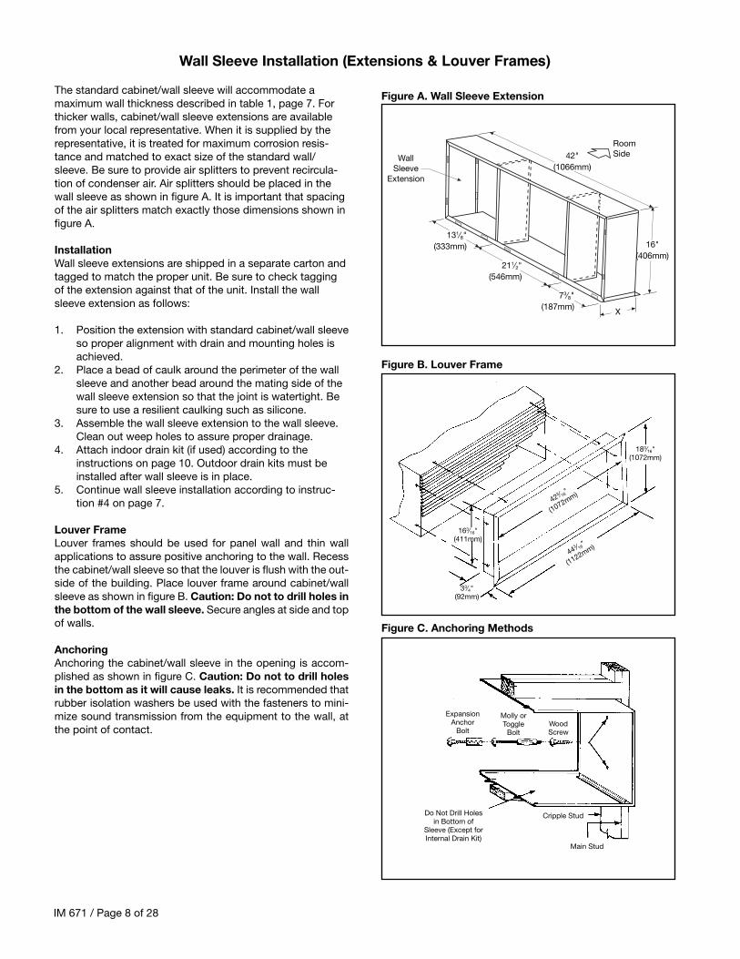
The standard cabinet/wall sleeve will accommodate amaximum wall thickness described in table 1, page 7. Forthicker walls, cabinet/wall sleeve extensions are availablefrom your local representative. When it is supplied by therepresentative, it is treated for maximum corrosion resis-tance and matched to exact size of the standard wall/sleeve. Be sure to provide air splitters to prevent recircula-tion of condenser air. Air splitters should be placed in thewall sleeve as shown in figure A. It is important that spacingof the air splitters match exactly those dimensions shown infigure A.
InstallationWall sleeve extensions are shipped in a separate carton andtagged to match the proper unit. Be sure to check taggingof the extension against that of the unit. Install the wallsleeve extension as follows:
1. Position the extension with standard cabinet/wall sleeveso proper alignment with drain and mounting holes isachieved.
2. Place a bead of caulk around the perimeter of the wallsleeve and another bead around the mating side of thewall sleeve extension so that the joint is watertight. Besure to use a resilient caulking such as silicone.
3. Assemble the wall sleeve extension to the wall sleeve.Clean out weep holes to assure proper drainage.
4. Attach indoor drain kit (if used) according to theinstructions on page 10. Outdoor drain kits must beinstalled after wall sleeve is in place.
5. Continue wall sleeve installation according to instruc-tion #4 on page 7.
Louver FrameLouver frames should be used for panel wall and thin wallapplications to assure positive anchoring to the wall. Recessthe cabinet/wall sleeve so that the louver is flush with the out-side of the building. Place louver frame around cabinet/wallsleeve as shown in figure B. Caution: Do not to drill holes inthe bottom of the wall sleeve. Secure angles at side and topof walls.
AnchoringAnchoring the cabinet/wall sleeve in the opening is accom-plished as shown in figure C. Caution: Do not to drill holesin the bottom as it will cause leaks. It is recommended thatrubber isolation washers be used with the fasteners to mini-mize sound transmission from the equipment to the wall, atthe point of contact.
Electric SubbaseAn electrical subbase is optional for all 208V and 230V units.A subbase is standard for all 265V units. The standard is avail-able with 3". (76mm) or 4" (102mm) heights. The subbase con-tains leveling legs for adjustment of up to 1" (25mm) addi-tional height. All subbases are factory supplied.
Installation1. If the minimum depth subbase is required, discard the side
extension pieces.2. If more than the minimum depth is required, determine the
depth of the side extension pieces desired and break atproper score - line. Insert the extension pieces into the
front assembly and secure with two short black screws ateach side.
3. Insert leveling bolts into subbase bottom flange. Four (4)bolts will be needed if side extensions are used. Only two(2) bolts are required if side extensions are not used.
4. Place the subbase on the floor and align its center linewith the center line of the wall opening. Do not fasten thesubbase to the floor. Attach the subbase to the cabinet/wall sleeve using the clips provided with the subbase.
5. The wiring should be roughed in and the conduit connectedto the subbase junction box. Complete the installation bywiring the receptacle to the incoming power supply.
Hydronic SubbaseA subbase is supplied as standard with all hydronic units. Thissubbase measures 8" (203mm) in height and includes thehydronic heating coil. Refer to IM Bulletin 419 for installationdetails. In addition, rough in supply and return piping.
Electrical and plumbing rough-in can be done through the backof the hydronic heat section or through the openings providedin the bottom of the subbase. The finished piping can be donenow or later.
Subbase Installation
Figure 12. Electric Subbase
Figure 13. Hydronic Subbase
ElectricalJunctionBox for MainPower Connection
Receptacle (Req’don 265V Units)
Plug/Cord Cover(Req’d on 265VUnits)
Knockouts forOpitonal Fuse &
Disconnect Switch
C L
ElectricalKnockouts
3" (76mm) or4" (102mm)
0" (0mm) to1" (25mm)
411⁄2"(1054mm)
Leveling Screw (4 Places)
17"(432mm)
12"(305mm)
5"(127mm)21⁄2"
(63.5mm)
0" (0mm) to 93⁄8"(238mm)
43⁄8" (111mm)
11⁄2" (38mm)
7⁄8"(22mm)
5⁄8"(16mm)
3"
Plan
Front Elevation (Three Front Panels in Place)
3" x 5"(76 to 127mm)Opening forElectrical and/orDrain Rough-In
3" x 5" Opening for Electricaland/or Piping Rough-in
Optional FuseDisconnect
PermanentMesh Filter
ElectricalKnockout
NOTES:1. Side channels are adjustable from 0"–93/8" in
length by inverting them. Side channels arepredrilled to allow infinite adjustment.
2. Subbase shown with louvered front panelremoved. Front panel is hinged to allowaccess to valve, coil, filter & electricaljunction box.
3. Leveling legs are adjustable from 1/4"–11/4".Top View
Front ViewEnd View
Leveling Legs
IM 671 / Page 10 of 28
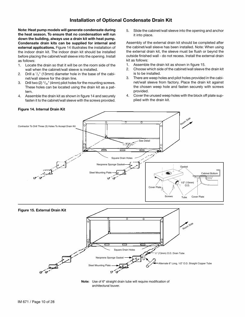
Note: Heat pump models will generate condensate duringthe heat season. To ensure that no condensation will rundown the building, always use a drain kit with heat pump.Condensate drain kits can be supplied for internal andexternal applications. Figure 14 illustrates the installation ofthe indoor drain kit. The indoor drain kit should be installedbefore placing the cabinet/wall sleeve into the opening. Installas follows:1. Locate the drain so that it will be on the room side of the
wall when the cabinet/wall sleeve is installed.2. Drill a 1/2" (13mm) diameter hole in the base of the cabi-
net/wall sleeve for the drain line.3. Drill two (2) 5/32" (4mm) pilot holes for the mounting screws.
These holes can be located using the drain kit as a pat-tern.
4. Assemble the drain kit as shown in figure 14 and securelyfasten it to the cabinet/wall sleeve with the screws provided.
5. Slide the cabinet/wall sleeve into the opening and anchorit into place.
Assembly of the external drain kit should be completed afterthe cabinet/wall sleeve has been installed. Note: When usingthe external drain kit, the sleeve must be flush or beynd theoutside finished wall - do not recess. Install the external drainkit as follows:1. Assemble the drain kit as shown in figure 15.2. Choose which side of the cabinet/wall sleeve the drain kit
is to be installed.3. There are weep holes and pilot holes provided in the cabi-
net/wall sleeve from factory. Place the drain kit againstthe chosen weep hole and fasten securely with screwsprovided.
4. Cover the unused weep holes with the block off plate sup-plied with the drain kit.
Installation of Optional Condensate Drain Kit
Figure 14. Internal Drain Kit
Figure 15. External Drain Kit
Cover PlateTube
Gasket
Screws
Cover Plate
1/2" (13mm)O.D.
Cabinet Bottom
Contractor To Drill Three (3) Holes To Accept Drain Kit
Square Drain Holes
Neoprene Sponge Gasket
Steel Mounting Plate
See Detail
Room Side
Note: Use of 6" straight drain tube will require modification ofarchitectural louver.
Square Drain Holes
Neoprene Sponge Gasket
Steel Mounting Plate
Room Side
1/2" (13mm) O.D. Drain Tube
Alternate 6" Long, 1/2" O.D. Straight Copper Tube
IM 671 / Page 11 of 28
1 Remove louver and mounting hardware from the ship-ping carton.
3. Make a temporary handle by looping a piece of flexiblewire or heavy cord through the louver. This enables theinstaller to keep a firm grasp on the louver when installingfrom inside the room.
Proper installation of the heating/cooling chassis is extremelyimportant to the proper operation of the unit. Whether the wallsleeve has been separately shipped or shipped with thechassis, proper installation is as follows:1. Remove shipping carton and inspect for any shipping
damage. Report any found to the carrier.2. Save shipping carton to cover installed conditioner until
construction is complete.3. Check nameplate data on chassis to insure that the cor-
rect job site distribution has been made with respect toheating/cooling capacities. Generally, corner rooms re-quire larger capacities.
4. Set front panel and air filter aside.5. Remove chassis from carton by pulling evenly on sub-
stantial portion of unit. Caution: Do not pull on Evapo-rator Top Panel.
6. If wall sleeve has been previously installed, removetemporary cardboard weather panel.
7 If louver has been previously installed, remove temporarycardboard weather panel.
8 Place Tinnerman clips on wall sleeve. Clips and mount-ing screws enclosed in a bag attached to the inside chas-sis side panel.
9. Rotate fans to be sure they are free of obstruction.10. Check all fasteners to make certain they did not loosen
during shipment. Do not loosen nuts holding down com-pressor; they are factory installed.
11. Do not lubricate motors before start-up. Motors are fac-tory lubricated. Consult “Scheduled Maintenance” sec-tion on page 13 for lubrication instructions.
12. Check all copper tubing and capillaries for proper clear-ance so they will not hit or rub during operation.
13. Slide chassis into wall sleeve until firmly seated againstweather seals. Caution: Do not push on coil surface,control box cover or fan scroll. Make sure tubing doesnot catch when inserting chassis.
14. Secure the chassis in the cabinet/wall sleeve with four (4)screws packaged with the Tinnerman clips.
15. Plug electrical cord into receptacle. Excess cord for 208Vand 230V units should be coiled neatly and stored in theconditioner. Attach plug/cord cover to front face of sub-base on 265V.
16. Set the manual damper operator in open or closed posi-tion as desired. On units equipped With the optional elec-
4. Angle the louver through the opening at the rear of thewall box, then pull the louver back to the wall sleeve flangeso that the louver studs pass through the holes in theflange.
5. Attach washers and nuts and secure louver in place.6. If the heating/cooling chassis is not to be immediately
installed, replace the weather panel.
tric fresh air damper, set the “auto/off” switch to the de-sired position. In “auto,” the damper is open when everthe fan motor is running. The auto/off' switch is locatedon the bottom front face of the control box.
17. Check the “Override/Normal” dial (heat pump only) lo-cated on the top of the unit to the left of the controls. Fornormal heat pump operation, position the dial clockwise,to “Normal”. Only the electric heater will operate whendial is in “Override” position,(maximum counter clockwise).
18. Set fan cycle switch (located on the lower front face ofthe control box) for constant or cycling indoor fan. Withthe switch in the “cycle” position, the indoor fan will shutoff when the thermostat shuts off heating or cooling.
19. Set the temperature limiting feature to the desired rangeof thermostat operations. As shipped, the range is 65°Fto 85°F.
20. Replace the air filter and front panel.21. For hydronic units:
a. Route the two low voltage valve wires, with Molex con-nection, through the opening provided in the subbase andconnect to valve.
b. Connect short power cord from the chassis to the recep-tacle in the subbase heat section.
c. Relocate thermostat bulb to bracket located in the sub-base. Refer to IM419 which is provided with the hydronicsubbase.
d. Replace filter and louvered subbase front panel.22. When installing the E vintage chassis in older wall sleeves,
bend the Sheet metal flange at the rear of the wall sleeverails to allow full insertion of the chassis.
Installation of Louvers
Installation of Chassis
Figure 16. Chassis Installation
Factory SuppliedHoles (2)
Tinnerman Clips
Chassis
Damper Actuator
Wall Sleeve Rails(See Note 22 Above)
Wall Sleeve
IM 671 / Page 12 of 28
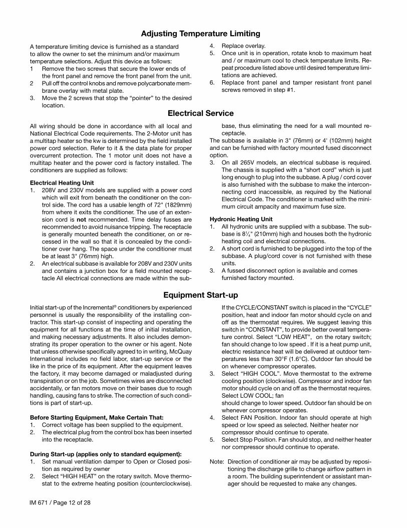
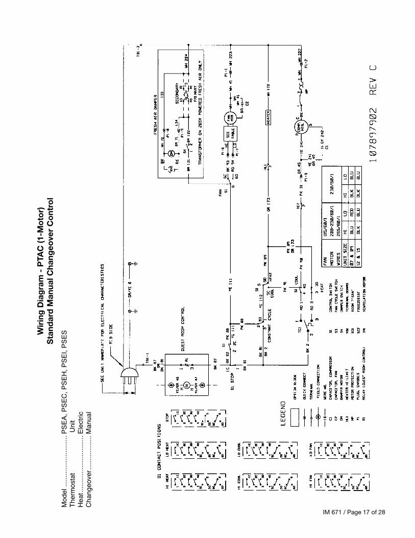
All wiring should be done in accordance with all local andNational Electrical Code requirements. The 2-Motor unit hasa multitap heater so the kw is determined by the field installedpower cord selection. Refer to it & the data plate for properovercurrent protection. The 1 motor unit does not have amultitap heater and the power cord is factory installed. Theconditioners are supplied as follows:
Electrical Heating Unit1. 208V and 230V models are supplied with a power cord
which will exit from beneath the conditioner on the con-trol side. The cord has a usable length of 72" (1829mm)from where it exits the conditioner. The use of an exten-sion cord is not recommended. Time delay fusses arerecommended to avoid nuisance tripping. The receptacleis generally mounted beneath the conditioner, on or re-cessed in the wall so that it is concealed by the condi-tioner over hang. The space under the conditioner mustbe at least 3" (76mm) high.
2. An electrical subbase is available for 208V and 230V unitsand contains a junction box for a field mounted recep-tacle All electrical connections are made within the sub-
A temperature limiting device is furnished as a standardto allow the owner to set the minimum and/or maximumtemperature selections. Adjust this device as follows:1 Remove the two screws that secure the lower ends of
the front panel and remove the front panel from the unit.2 Pull off the control knobs and remove polycarbonate mem-
brane overlay with metal plate.3. Move the 2 screws that stop the “pointer” to the desired
location.
Initial start-up of the Incremental® conditioners by experiencedpersonnel is usually the responsibility of the installing con-tractor. This start-up consist of inspecting and operating theequipment for all functions at the time of initial installation,and making necessary adjustments. It also includes demon-strating its proper operation to the owner or his agent. Notethat unless otherwise specifically agreed to in writing, McQuayInternational includes no field labor, start-up service or thelike in the price of its equipment. After the equipment leavesthe factory, it may become damaged or maladjusted duringtranspiration or on the job. Sometimes wires are disconnectedaccidentally, or fan motors move on their bases due to roughhandling, causing fans to strike. The correction of such condi-tions is part of start-up.
Before Starting Equipment, Make Certain That:1. Correct voltage has been supplied to the equipment.2. The electrical plug from the control box has been inserted
into the receptacle.
During Start-up (applies only to standard equipment):1. Set manual ventilation damper to Open or Closed posi-
tion as required by owner2. Select “HIGH HEAT” on the rotary switch. Move thermo-
stat to the extreme heating position (counterclockwise).
4. Replace overlay.5. Once unit is in operation, rotate knob to maximum heat
and / or maximum cool to check temperature limits. Re-peat procedure listed above until desired temperature limi-tations are achieved.
6. Replace front panel and tamper resistant front panelscrews removed in step #1.
base, thus eliminating the need for a wall mounted re-ceptacle.
The subbase is available in 3" (76mm) or 4' (102mm) heightand can be furnished with factory mounted fused disconnectoption.3. On all 265V models, an electrical subbase is required.
The chassis is supplied with a “short cord” which is justlong enough to plug into the subbase. A plug / cord coveris also furnished with the subbase to make the intercon-necting cord inaccessible, as required by the NationalElectrical Code. The conditioner is marked with the mini-mum circuit ampacity and maximum fuse size.
Hydronic Heating Unit1. All hydronic units are supplied with a subbase. The sub-
base is 81⁄4" (210mm) high and houses both the hydronicheating coil and electrical connections.
2. A short cord is furnished to be plugged into the top of thesubbase. A plug/cord cover is not furnished with theseunits.
3. A fussed disconnect option is available and comesfurnished factory mounted.
If the CYCLE/CONSTANT switch is placed in the “CYCLE”position, heat and indoor fan motor should cycle on andoff as the thermostat requires. We suggest leaving thisswitch in “CONSTANT”, to provide better overall tempera-ture control. Select “LOW HEAT”, on the rotary switch;fan should change to low speed . If it is a heat pump unit,electric resistance heat will be delivered at outdoor tem-peratures less than 30°F (1.6°C). Outdoor fan should beon whenever compressor operates.
3. Select “HIGH COOL”. Move thermostat to the extremecooling position (clockwise). Compressor and indoor fanmotor should cycle on and off as the thermostat requires.Select LOW COOL; fanshould change to lower speed. Outdoor fan should be onwhenever compressor operates.
4. Select FAN Position. Indoor fan should operate at highspeed or low speed as selected. Neither heater norcompressor should continue to operate.
5. Select Stop Position. Fan should stop, and neither heaternor compressor should continue to operate.
Note: Direction of conditioner air may be adjusted by reposi-tioning the discharge grille to change airflow pattern ina room. The building superintendent or assistant man-ager should be requested to make any changes.
Adjusting Temperature Limiting
Electrical Service
Equipment Start-up
IM 671 / Page 13 of 28
Units that are furnished with remote mounted thermostatsshould be wired as shown in Figure 17. Other considerationsfor this arrangement are as follows:1. When wiring the low voltage plug and receptacle discon-
nect, provide enough wire to move harness out of theway for chassis removal
2. If subbase is used, a small hole must be drilled andgrommeted in the subbase front to allow passage of thelow voltage wires.
3. If slave units are to be employed, connects shown in Fig-ure 17. With this arrangement, the loop between termi-nals N2 and N4 of the slave unit must be severed. Thestandard master transformer handles 10 VA power drawand each slave unit draws 5VA. If more than one slaveunit is used, the master transformer must be replacedwith a larger one. The number of slave units that can beconnected is limited to the maximum amperage rating ofthe thermostat contacts.
4. When using a programmable wall thermostat, splice intothe jumper going from N2 to N4 of the master unit andconnect it to the common terminal of the thermostat. Referto the instructions furnished with the chosen thermostatto locate the common terminal. Note: It may be neces-sary to place a larger VA transformer in the unit whenusing certain programmable thermostats. Check the VAdraw of the chosen thermostat,
Incremental conditioners are built to last. With proper care,the unit should provide uninterrupted service for many years.Scheduled maintenance of this equipment as described bel-low, is the key to the equipment's longevity.
A. Air filters must be cleaned at regular intervals. Twice an-nually may be adequate in some areas while twice monthlymay be required in others. Areas with high dirt and lintcontent or heavy usage of units require more frequentfilter maintenance than those areas of relatively cleanoperating or low usage conditions. Unit malfunction willoccur if air filters are not kept clean. Rinse filter with hotwater and a mild detergent. Let dry and oil lightly to en-hance dust collecting ability.
B. McQuay recommends that every year the chassis be re-moved for a thorough checkup. This should be completedas follows:
1. Unplug unit from power source.2. Remove front panel.3. Remove chassis from cabinet and move it to the mainte-
nance department. Replace with spare chassis or weatherplate.
4. Check all seals and Insulation and repair as required.5. Check all wiring and controls for hazardous conditions.6. Thoroughly clean discharge grilles.7. Cover motors and control module with water tight mate-
rial and wash evaporator coil, condenser coil and basepan using hot water and a mild soap.
Residential and institutional cleaning compounds can causepermanent damage to the packaged terminal unit. To avoiddamage to unit controls and heat transfer surfaces, do notspray cleaning compounds onto the discharge grille, returnair opening, or unit controls. Normal cleaning can be accom-plished by wiping the unit surface with a damp cloth. Whenusing cleaning compounds on carpets, floors or walls, turnthe unit off to avoid drawing potentially damaging vapors intothe package terminal unit.
8. Clean condensate drain and clear weep holes.9. Dry equipment thoroughly, especially electric parts and
installation. 10. Clean any rust spots with steel wool andpaint with rust inhibiting paint.
11. Clean insulation or replace if necessary.12. Check insulation on refrigeration piping and replace if
necessary.13. Check all fasteners and tighten as required.14. Clean and oil damper door and linkage.15. Test run chassis before reinstalling.
An inherent advantage of the Incremental system is that fail-ure of any part affects only one incremental conditioner anddoes not interrupt the operation of the rest of the system. Afurther advantage is that a failed part can be quickly and eas-ily replaced, thus minimizing the inoperative time of the equip-ment. This is so, however, only if a replacement part is quicklyavailable. In order to replace a failed part quickly and keep allincremental conditioners in good operating condition, McQuayInternational recommends that at the time incremental condi-tioners are purchased, owners arrange for a small stock ofreplacement parts.Where an owner carries such a stock, immediate replacementparts of defective part is possible. The defective part can thenbe returned to McQuay International or one its authorized ser-vice stations. So long as it is still in warranty, it is repaired orreplaced and returned to the owner with out cost for shoplabor and material. Thus, the stock of replacement parts isconstantly replenished. To the right is listed the kinds of partswhich McQuay International recommends to be carried in
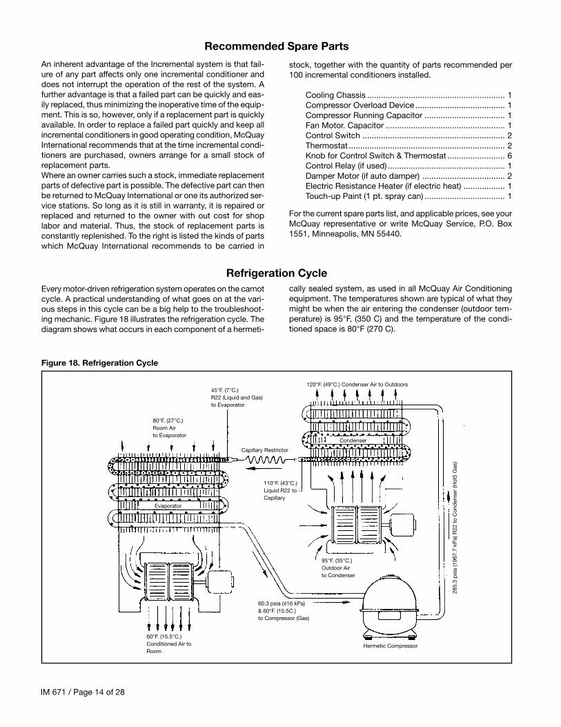
Every motor-driven refrigeration system operates on the carnotcycle. A practical understanding of what goes on at the vari-ous steps in this cycle can be a big help to the troubleshoot-ing mechanic. Figure 18 illustrates the refrigeration cycle. Thediagram shows what occurs in each component of a hermeti-
cally sealed system, as used in all McQuay Air Conditioningequipment. The temperatures shown are typical of what theymight be when the air entering the condenser (outdoor tem-perature) is 95°F, (350 C) and the temperature of the condi-tioned space is 80°F (270 C).
stock, together with the quantity of parts recommended per100 incremental conditioners installed.
Cooling Chassis ............................................................ 1Compressor Overload Device ....................................... 1Compressor Running Capacitor ................................... 1Fan Motor. Capacitor .................................................... 1Control Switch .............................................................. 2Thermostat .................................................................... 2Knob for Control Switch & Thermostat ......................... 6Control Relay (if used) ................................................... 1Damper Motor (if auto damper) .................................... 2Electric Resistance Heater (if electric heat) .................. 1Touch-up Paint (1 pt. spray can) ................................... 1
For the current spare parts list, and applicable prices, see yourMcQuay representative or write McQuay Service, P.O. Box1551, Minneapolis, MN 55440.
2. Blowers operate on cool but compressordoes not start
3. Blowers run on cool and compressor starts but stopsafter a short interval.
4. Blowers run on cool and compressor starts and runs,but compressor occasionally stops (on overload device).
5. Compressor starts and runs on cool butblowers do not run.
6. Compressor starts and runs on cool, but fan motor starts,then stops.
7. Equipment gives electrical shock.
3. Insufficient cooling capacity.
a. No power
b. Faulty push-button switchc. Loose connections at push-button switch
a. Thermostat set too high.b. Heat valve is open and heat is on.c. Low voltage.d. Faulty push-button switch.e. Faulty connection at push-button switch.f. Defective wiring to thermostat.g. Loose connections at compressor terminals.h. Wiring to compressor terminals defective.i. Loose connections in compressor overload device.
j. Starting capacitor malfunctions (open circuited, shortcircuited or loss of capacity).
k. Defective compressor motor (short circuited, open cir-cuited, grounded).
a. Operation of overload device due to overloading com-pressor motor.
a. Low voltage due to overload circuits within building orthroughout the local power system. Due to varying powerdemands, this condition might exist only at certain timesduring the day or on very hot days.
b. High voltage due to fluctuations in local power system;usually occurs during low load periods of the day
c. Partial short circuit in compressor motor. Under normalloading a compressor with a partial short circuit mightappear to be operating all right; increased condensingair temperature might then cause a short.
a. Faulty push button switch.b. Open circuited blower motor.c. Blower rubbing against its housing.d. Bearings on blower motor seized.e. Loose connection at push-button switch.
a. Operation of the internally connected overload devicedue to a short circuit in blower motor.
b. Windings, rubbing of blower wheel or lack of lubricationin blower motor bearings.
a. Grounded electrical circuit.
a. Equipment standing too long without being run.
b. Insufficient airflow through condenser due to:1) Dirty condenser.2) 0bstructed louver on outer cabinet or wall
box.3) Condenser blower/fan not running.4) Condenser blower/fan not up to speed.5) Condenser blower/fan slipping on motor
shaft.6) Recirculation of condenser air.
c. Insufficient airflow through evaporator due to:1) Dirty evaporator.2) Ice on evaporator coils.3) Dirty air filter.4) Obstructed discharge grilles.5) Evaporator blower motor not running.6) Evaporator blower motor not up to speed.7) Evaporator motor slipping on motor shaft.
d. Heat load in room exceeds capacity of equipment.e. Windows and doors in room are openf. Compressor not pumping, indicated by:
1) Low wattage.2) Condenser not warm, evaporator only
partially cool or not at all .g. Restricted capillary or strainer.
1 ) Frost on capillary or strainer2) Low wattage.3) Condenser not warm.4) Evaporator partially frosted, only partially cool
or not at all.
a. Check supply line fusses, circuit breakers, and be surethe power is on. Blown fuses would indicate circuit over-loading, a short circuit, or a ground condition in the cir-cuit Voltage supply to the equipment should be checked.Voltage underload must be within 10% of voltage givenon date plate.
b. Replace.c Tighten.
a. Adjust Rotate control knob to “Cooler."b. Close heat valve.c. Check as above.d. Replace.e. Tighten.f. Replace.g. Tighten.h. Replace.i. Tighten.
j. Replace.
k. * Ship cooling chassis prepaid to nearest McQuay au-thorized warranty station.
a. Check voltage supply. Clean condenser inside and out.Check at outside face of condenser for recirculation ofcondenser air. Put air "splitters" in, if missing. Checkcompressor for short circuit. If defective, ship coolingchassis to nearest McOuay authorized warranty station.
a. Run separate electric line to equipment Consult localpower company.
b. Consult local power company.
c. If confirmed, ship cooling chassis prepaid to nearestMcOuay authorized warranty station.
a. Replace.b. Replace.c. Adjust blower motor or blower wheel position.d. Replace motore. Tighten.
a. Replace motor
b. Adjust blower wheel or motor, or replace.
a. Eliminate ground.
a. If the air conditioner is allowed to stand for an extendedlength of time without being run on cool, it is possiblefor all the refrigerant to become absorbed in the oil in-side the compressor and refrigeration circuit. If thisshould happen there will be no cooling until the neces-sary working pressures have been established. This willtake about 5 minutes of continuous running.
b.1) Clean.2) Remove obstructions.3) Check same as in the case of malfunctioning
condenser air blower.4) Check for correct voltage. Replace blower motor
if necessary5) Adjust blower position and tighten setscrews.6) Correct as in No 3 above.
c.1) Clean.2) Turn equipment off to let ice melt (see last
two items of No. 9 “Too much cooling," on page 15.3) Clean or replace.4) Remove obstructions.5) Check as in No.1.6) Check for correct voltage. Replace motor if necessary.7) Adjust blower wheel position and tighten setscrew
d. Refer to original load calculations, recalculate heat load.e. Close them.f. * Ship prepaid to nearest McQuay warranty
station.
g. * Ship prepaid to nearest McOuay warrantystation.
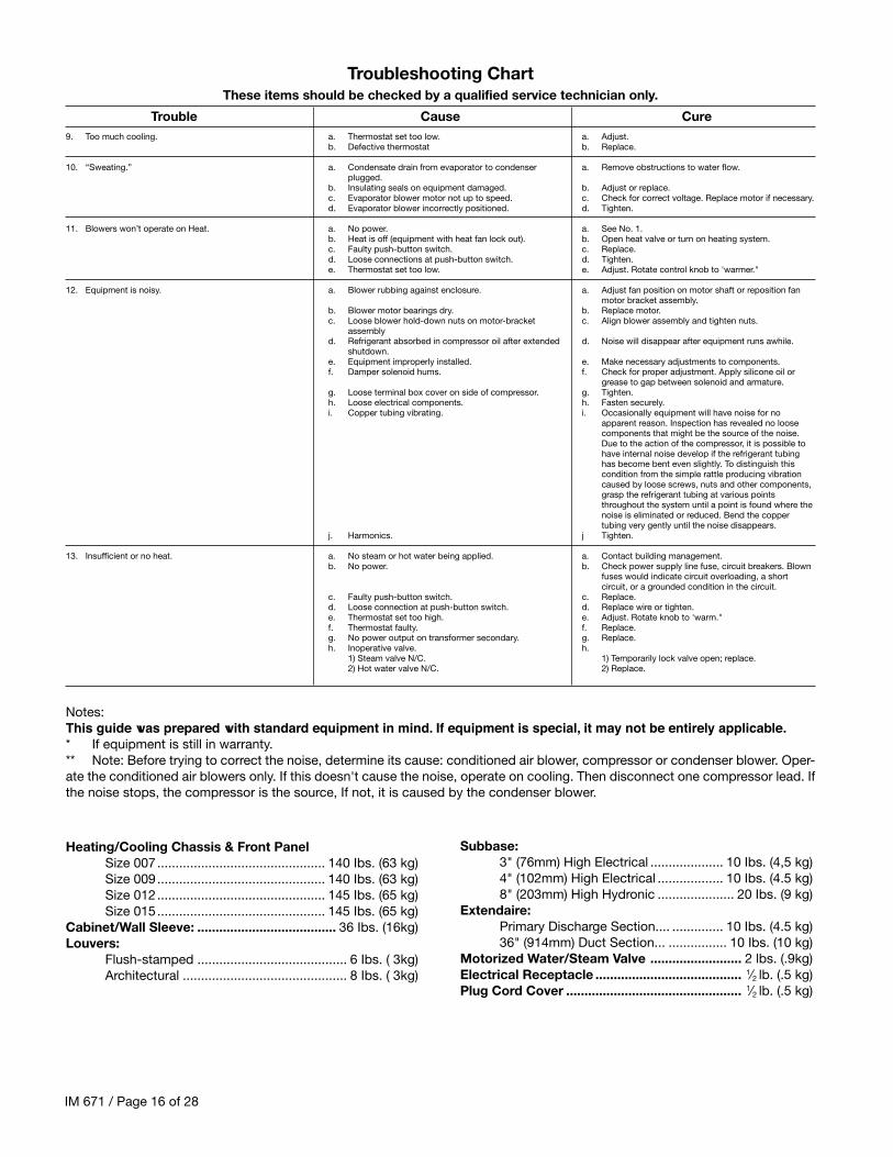
Troubleshooting ChartThese items should be checked by a qualified service technician only.
Trouble Cause Cure
IM 671 / Page 16 of 28
9. Too much cooling.
10. “Sweating.”
11. Blowers won’t operate on Heat.
12. Equipment is noisy.
13. Insufficient or no heat.
a. Thermostat set too low.b. Defective thermostat
a. Condensate drain from evaporator to condenserplugged.
b. Insulating seals on equipment damaged.c. Evaporator blower motor not up to speed.d. Evaporator blower incorrectly positioned.
a. No power.b. Heat is off (equipment with heat fan lock out).c. Faulty push-button switch.d. Loose connections at push-button switch.e. Thermostat set too low.
a. Blower rubbing against enclosure.
b. Blower motor bearings dry.c. Loose blower hold-down nuts on motor-bracket
assemblyd. Refrigerant absorbed in compressor oil after extended
g. Loose terminal box cover on side of compressor.h. Loose electrical components.i. Copper tubing vibrating.
j. Harmonics.
a. No steam or hot water being applied.b. No power.
c. Faulty push-button switch.d. Loose connection at push-button switch.e. Thermostat set too high.f. Thermostat faulty.g. No power output on transformer secondary.h. Inoperative valve.
1) Steam valve N/C.2) Hot water valve N/C.
a. Adjust.b. Replace.
a. Remove obstructions to water flow.
b. Adjust or replace.c. Check for correct voltage. Replace motor if necessary.d. Tighten.
a. See No. 1.b. Open heat valve or turn on heating system.c. Replace.d. Tighten.e. Adjust. Rotate control knob to 'warmer."
a. Adjust fan position on motor shaft or reposition fanmotor bracket assembly.
b. Replace motor.c. Align blower assembly and tighten nuts.
d. Noise will disappear after equipment runs awhile.
e. Make necessary adjustments to components.f. Check for proper adjustment. Apply silicone oil or
grease to gap between solenoid and armature.g. Tighten.h. Fasten securely.i. Occasionally equipment will have noise for no
apparent reason. Inspection has revealed no loosecomponents that might be the source of the noise.Due to the action of the compressor, it is possible tohave internal noise develop if the refrigerant tubinghas become bent even slightly. To distinguish thiscondition from the simple rattle producing vibrationcaused by loose screws, nuts and other components,grasp the refrigerant tubing at various pointsthroughout the system until a point is found where thenoise is eliminated or reduced. Bend the coppertubing very gently until the noise disappears.
j Tighten.
a. Contact building management.b. Check power supply line fuse, circuit breakers. Blown
fuses would indicate circuit overloading, a shortcircuit, or a grounded condition in the circuit.
c. Replace.d. Replace wire or tighten.e. Adjust. Rotate knob to 'warm."f. Replace.g. Replace.h.
Troubleshooting ChartThese items should be checked by a qualified service technician only.
Trouble Cause Cure
Notes:This guide was prepared with standard equipment in mind. If equipment is special, it may not be entirely applicable.* If equipment is still in warranty.** Note: Before trying to correct the noise, determine its cause: conditioned air blower, compressor or condenser blower. Oper-ate the conditioned air blowers only. If this doesn't cause the noise, operate on cooling. Then disconnect one compressor lead. Ifthe noise stops, the compressor is the source, If not, it is caused by the condenser blower.
This document contains the most current product information as of this printing. For the most up-to-dateproduct information, please go to www.mcquay.com.