Page 1 of 18 Controls Southeast, Inc. To: CSI Customer From: Controls Southeast, Inc. Date: Feb-2013 Re: ControTrace Heating System for 110 ft Diameter Sulfur Tank Introduction While internal coils have proven to be an effective means of keeping the sulfur in a molten state, they do not prevent tank corrosion. Sulfur tanks corrode from the outside due to water intrusion under the insulation. Sulfur tanks corrode from the inside due to wet sulfur contact corrosion. Wet sulfur contact corrosion can cause a build-up of iron sulfide which can lead to tank fires. The root cause of the tank corrosion is that internal steam coils are not able to maintain the tank shell / roof above the sulfur freezing point. The coils themselves are also susceptible to corrosion; when an internal coil fails, the repair is costly and time consuming. Some tank owners, who choose not to address the tank corrosion, choose to use stainless steel coils to address the coil corrosion. This approach results in a more robust heating system, but also adds considerable cost. CSI's external heating system heats the entire external surface of the tank and roof to prevent sulfur condensation and subsequent corrosion and iron sulfide build-up. External heating panels are not susceptible to corrosion and are easily serviced in the unlikely event of a failure. In the event of an upset condition resulting in extended down time, a ControTrace heating system can effectively re-melt any solidified sulfur and return the tank to service. Thus CSI’s external heating system provides superior performance, extended service life, reduced maintenance, and increased safety. Internal Heating System The traditional sulfur tank heating system utilizes internal, submerged steam coils to provide heat directly to the sulfur. This system is effective at keeping the sulfur molten, but does not provide heat to the tank shell or roof. Sulfur tanks have been observed to corrode frequently and rapidly using this configuration. Because the tank shell and roof temperature is below the freezing point of sulfur, sulfur vapor in the tank will tend to condense onto the tank surfaces. The built-up sulfur insulates the tank surface, further reducing the surface temperature. This allows water to condense at the tank surface which results in rapid wet-sulfur contact corrosion. Under this scenario, the tank corrodes from the inside-out. This corrosion mechanism produces iron sulfide as a by-product. Iron sulfide is pyrophoric and, under the right circumstances, can result in a tank fire. A second common corrosion mechanism is due to the presence of water on the outside of the tank under the insulation. With a cold tank shell / roof, any water which penetrates the insulation will sit against the tank and cause corrosion. Another problem frequently observed with internal coils is corrosion of the coils themselves. If a coil corrodes and leaks, significant
Transcript
Page 1 of 18
Controls Southeast, Inc.
To: CSI Customer From: Controls Southeast, Inc. Date: Feb-2013 Re: ControTrace Heating System for 110 ft Diameter Sulfur Tank Introduction While internal coils have proven to be an effective means of keeping the sulfur in a molten state, they do not prevent tank corrosion. Sulfur tanks corrode from the outside due to water intrusion under the insulation. Sulfur tanks corrode from the inside due to wet sulfur contact corrosion. Wet sulfur contact corrosion can cause a build-up of iron sulfide which can lead to tank fires. The root cause of the tank corrosion is that internal steam coils are not able to maintain the tank shell / roof above the sulfur freezing point. The coils themselves are also susceptible to corrosion; when an internal coil fails, the repair is costly and time consuming. Some tank owners, who choose not to address the tank corrosion, choose to use stainless steel coils to address the coil corrosion. This approach results in a more robust heating system, but also adds considerable cost. CSI's external heating system heats the entire external surface of the tank and roof to prevent sulfur condensation and subsequent corrosion and iron sulfide build-up. External heating panels are not susceptible to corrosion and are easily serviced in the unlikely event of a failure. In the event of an upset condition resulting in extended down time, a ControTrace heating system can effectively re-melt any solidified sulfur and return the tank to service. Thus CSI’s external heating system provides superior performance, extended service life, reduced maintenance, and increased safety. Internal Heating System The traditional sulfur tank heating system utilizes internal, submerged steam coils to provide heat directly to the sulfur. This system is effective at keeping the sulfur molten, but does not provide heat to the tank shell or roof. Sulfur tanks have been observed to corrode frequently and rapidly using this configuration. Because the tank shell and roof temperature is below the freezing point of sulfur, sulfur vapor in the tank will tend to condense onto the tank surfaces. The built-up sulfur insulates the tank surface, further reducing the surface temperature. This allows water to condense at the tank surface which results in rapid wet-sulfur contact corrosion. Under this scenario, the tank corrodes from the inside-out. This corrosion mechanism produces iron sulfide as a by-product. Iron sulfide is pyrophoric and, under the right circumstances, can result in a tank fire. A second common corrosion mechanism is due to the presence of water on the outside of the tank under the insulation. With a cold tank shell / roof, any water which penetrates the insulation will sit against the tank and cause corrosion. Another problem frequently observed with internal coils is corrosion of the coils themselves. If a coil corrodes and leaks, significant
Page 2 of 18
Controls Southeast, Inc.
quantities of water will be introduced to the tank; the additional water accelerates the wet sulfur contact corrosion. Additionally, the damaged coils are not readily accessible; repairs are costly, time consuming, and require the tank to be taken out of service. This is often addressed by using stainless steel coils –an approach which effectively reduces the corrosion rate but adds considerable cost to the tank. Destructive corrosion of sulfur tanks is often more significant than owners/operators realize. Many facilities do not have tank inspection programs in place to monitor tank wall thinning. A sulfur tank may last 5-10 years without any visible signs of degradation; but once the tank develops a hole, the situation becomes more urgent. A corroding sulfur tank also presents safety issues as tank failure and tank fires can create hazardous, uncontrolled conditions. (Reference Appendix 1 for photographs of corrosion observed in sulfur tanks) Tank Heating System Evolution The approach used for heating sulfur tanks has been gradually progressing over the past 30+ years. Many early sulfur tanks using only internal coils experienced significant corrosion. Some also experienced tank fires due to iron sulfide and roof collapse due to corrosion and solid sulfur build-up. A variety of steam coil designs (both external and internal) have been applied to sulfur tank roofs and shells in an attempt to reduce the corrosion rate. Use of both internal coils and shell / roof heating has not solved the corrosion issue. The internal coils, which are subject to corrosion, remain inside the tank and the shell / roof heating systems are often inadequate to maintain the required temperature; CSI has replaced inadequate shell / roof heating systems on several sulfur tanks. In the past 10+ years, the industry has been moving away from these ad-hoc tank heating systems, towards engineered, external-only heating systems (Reference Appendix 5 for a partial list of tanks heated with CSI’s external heating system). An engineered, external heating system is capable of maintaining both the liquid sulfur temperature and the shell / roof temperature. An external-only heating system is usually less expensive than an ad-hoc internal / external heating system, especially when stainless steel coils are used. Even in cases where the external heating system is more expensive, the long-term savings in tank maintenance and repair will ultimately result in cost savings for the facility. Although difficult to quantify, the increased safety of an externally heated sulfur tank is another significant benefit. External Heating System A ControTrace external heating system provided by CSI maintains both the liquid sulfur temperature and the shell / roof temperature. Internal coils are eliminated and condensation on the shell / roof is prevented. This configuration has several key advantages:
• The temperature of the tank shell and roof is maintained above the sulfur freezing point to eliminate wet sulfur contact corrosion.
• The temperature of the tank shell and roof is maintained above the boiling point of water to eliminate corrosion under insulation due to water intrusion.
• With no internal coil the potential of a steam leak into the sulfur tank is eliminated.
Page 3 of 18
Controls Southeast, Inc.
• Tank maintenance is greatly simplified as the heating system is located outside of the tank instead of inside.
• The significantly reduced probability of corrosion and tank fires results in increased plant safety. ControTrace tank heating systems are designed based on finite-difference heat transfer modeling. The model considers all relevant heat transfer paths to, from, and within the tank as well as the temperature distribution in the tank walls and roof. The coverage density of the ControTrace heating elements is typically higher in the lower portion of the tank in order to accommodate a low liquid level and offset heat loss to the ground. The spacing between heating elements in the vapor space is critical to ensuring the minimum wall/roof temperature stays above the sulfur freezing point; this spacing is dictated by the modeling. CSI’s tank model has been confirmed through extensive applications across the world, field data from tanks in service, and CFD (computational fluid dynamics) modeling focused on the sulfur recirculation inside the tank. (Reference Appendix 2 for a brief summary of the CFD modeling) Key Design Considerations There are several key variables which have significant cost implications on the design of a ControTrace tank heating system. CSI recommends these variables be considered in order to optimize the total cost of the system:
• Sulfur maintenance temperature • Low liquid level height • Steam pressure • Sweep air flow rate • Insulation type and thickness
Based on a preliminary review of this sulfur tank, CSI has based calculations on the following conditions (Reference Appendix 5 for a full list of design assumptions):
• Sulfur maintenance temperature: 275°F was used as the minimum sulfur maintenance temperature. This is the maintenance temperature that CSI recommends to provide an appropriate factor of safety in the heating system design.
• Low liquid level height: The low liquid level is a key parameter for an external heating system because a very low liquid level results in a small contact area between the liquid and the heated shell. A low liquid level of 3 ft was assumed for this tank.
• Steam pressure: 60 psig steam was specified by Customer and considered for all calculations.
• Sweep air flow rate: The tank is vented via a single central vent and thus does not have continuous sweep air.
• Insulation type and thickness: CSI assumed an optimized insulation configuration using 6 in thick expanded perlite on the roof and 4 in thick mineral wool on the sides. Expanded perlite is recommended for the roof because of its crush resistance and mineral wool is recommended for the sides because of its high performance and value. CSI also recommends that the very bottom of the tank be insulated with foamglass in order to prevent insulation damage from ground surface rain water.
Page 4 of 18
Controls Southeast, Inc.
Note that steam pressures as high as 90 psig can be safely used on sulfur storage tanks without risk of overheating the sulfur. In a piping system, the process temperature will approach the heating medium temperature when the process is stagnant. This precludes the use of higher steam pressures on molten sulfur lines. But, in a storage tank, there is always an active heat loss path from the top and bottom surface of the sulfur. Thus the maximum possible sulfur temperature is significantly lower than the steam temperature. The use of higher steam pressures can allow for a reduction in the tracing coverage area and a corresponding reduction in the cost of the heating system. Sulfur Freezing and Re-melting CSI performed a detailed analysis of the sulfur freezing and re-melting performance of the planned 110 ft diameter tank. The analysis was based on a liquid level of 18 ft, the key design consideration listed above, and the detailed design assumptions listed in the Appendices (Reference Appendix 4 for a complete list of the design assumptions used for this analysis) Sulfur storage tanks cool very slowly due to the convergence of several different factors: (1) the tanks contain a large amount of sulfur with a large thermal capacitance, (2) the tanks are typically well insulated, and (3) the sulfur that freezes first forms an insulating layer that further slows the tank heat loss. The sulfur typically loses heat through the top surface to the vapor space, through the shell to ambient, and through the floor to the ground. CSI considered these three heat loss paths and performed a cool-down time analysis. The ground also has a large thermal capacitance. After several months of operation, the ground under the sulfur tank heats and is typically within 30°F of the sulfur temperature at a depth of 1 ft. When heating is removed from the sulfur tank the sulfur temperature begins to drop. After roughly 2 weeks, the sulfur temperature reaches the freezing temperature. At this point, the sulfur temperature and the ground temperature are roughly the same and the heat loss rate to the ground approaches zero. Thus, while the sulfur at the liquid surface and the tank shell continues to lose heat and freeze, the sulfur at the tank floor remains molten. As heat loss continues from the shell and the liquid surface, these surfaces begin to freeze over layer by layer. (Note that the frozen sulfur layer on the top surface will not sink unless an external disturbance causes a break in the frozen layer and allows less dense liquid sulfur to seep through) The following plot shows the sulfur freezing sequence. No freezing occurs in the first 13 days as the sulfur temperature is dropping from 275°F to the freezing temperature. The frozen layers then begin building up on the liquid surface and the shell. After an initial rapid build-up, the frozen sulfur forms an insulting layer and the sulfur deposition rate slows. The chart shows the thickness of the built-up layers (left side) as well as the total fraction of the sulfur that has solidified (right side).
Page 5 of 18
Controls Southeast, Inc.
Any consideration of re-melting a sulfur tank must also consider the duration for which the tank was left un-heated. As the above plot shows, a tank that is left unheated for several days will not accumulate any solidified sulfur. Of course, sulfur in the tank nozzles will freeze rather quickly as the nozzles have a relatively small volume and a large heat loss area. Frozen nozzles may lead some to believe that the tank has frozen when, in fact, it is only the sulfur near the inlets and outlets that has frozen. CSI calculated the time required to re-melt the solidified sulfur using a ControTrace heating system. Because the heating system is applied to the tank shell, the sulfur at the shell will melt first, followed by the sulfur at the surface. Three different down times, or utility loss durations, were considered. The chart below summarizes the results.
The results presented above are for a liquid level of 18 ft (~50% tank capacity). At lower liquid levels, the smaller sulfur mass will result in an earlier onset of freezing. After freezing begins, the sulfur
0%
5%
10%
15%
20%
25%
30%
35%
0.0
0.5
1.0
1.5
2.0
2.5
3.0
3.5
4.0
4.5
0 20 40 60 80 100 120
Fraction
Solidified
(%)
Crust T
hickne
ss (ft)
Time (days)
Solid Sulfur Accumulation vs. Time
Top Crust Thickness
Shell Crust Thickness
Fraction Solidified
Page 6 of 18
Controls Southeast, Inc.
solidification rate is approximately the same. Due to the smaller total volume of sulfur, the fraction of the sulfur that has solidified after a given period of time is higher. The melt-out time is extended slightly at lower liquid levels due to the reduced contact area between the sulfur and the heated shell. The table below compares the cooling and melting performance for a liquid level of 18 ft to a liquid level of 6 ft.
18 ft LL 6 ft LL Time at which freezing begins: 13 days 5 days
Fraction solidified after 30 days: 11.6% 32.9% Time to melt sulfur at shell: 41 hr 54 hr
Total melting time: 120 hr 160 hr CSI has not performed a melt-out analysis for a tank heated with an internal coil. An internal coil would likely perform better on a tank that had been down for a very long time, but may perform worse on a tank that had been down for only a short time. As an internal coil has direct contact with the sulfur, it can provide significantly more heat when the sulfur is cold. Thus a tank that experiences significant solidification will likely melt faster if it is re-heated using an internal coil. On the other hand, an internal coil does not provide direct heat to the wall, thus a tank that has experienced minimal solidification at the wall, might re-melt faster if heated with ControTrace. ControTrace System Configuration ControTrace bolt-on panels are made up of multiple ControTrace elements; each element is approximately 2 in wide. The elements are headered together to form a panel; the element spacing within the panel varies depending on the thermal requirements of the system. Panels are applied to both the shell and the roof. The shell panels are rectangular. Depending on the roof construction, the roof panels may be rectangular (checker-board) or radial (pie-slice). Panels near the bottom of the tank typically utilize more elements in order to provide adequate heat to the sulfur at the low liquid level. In all cases, each panel is custom made to fit the specific application. Panels can be made in nearly any configuration necessary to avoid interference with nozzles, supports, and other attachments. CSI simply needs to know where these items are located to assure that interference does not occur. (Reference Appendix 3 for photographs of ControTrace tank heating panels) During tank construction, threaded bosses are welded to the tank. The panels are then attached to the tank via bolting to the bosses. Before bolting, each panel receives a layer of heat transfer compound to create a conductive heat transfer path between the panel and the tank shell. Each panel can be installed independently. Insulation is installed after the panels. Steam supply/return lines and intermediate jump-overs are installed after the insulation. Each panel has an inlet and an outlet connection. The connections point away from the tank surface and protrude through the tank insulation. CSI–supplied jump-overs are then used to connect consecutive panel together. In this way, all connection points are located outside the insulation for easy inspection and, if necessary, repair. CSI’s jump-overs are insulated flexible metal hoses that are typically installed after the tank has been insulated. CSI’s standard connections are ¾” nominal diameter JIC fittings (reference the SAE J514 specification). These fittings require only a simple wrench for installation and can be disconnected and re-used indefinitely.
Page 7 of 18
Controls Southeast, Inc.
Multiple panels are daisy-chained together to form a single steam circuit. Each steam circuit requires its own steam supply and steam return (trap). A 110 ft diameter tank will typically require 40 to 50 steam circuits. Each circuit will supply at the roof (typically near the center), run along the roof radially, run down the shell vertically, and return at the base of the shell. Thus the steam supply points are grouped near the peak of the roof while the return points are distributed around the base of the shell. Typically, a steam supply manifold is located at the roof elevation and pre-insulated tubing is used to carry the steam to the individual circuits. The circuit returns are typically handled in one of two ways. Some customers run a steam return header around the base of the tank and return each circuit directly into the header (through a steam trap). Other customers locate one or more steam return (trap) manifolds at convenient locations and separately run each steam return to the manifold using pre-insulated tubing. By using tall panels (up to ~ 30 ft), the number of panels on the shell can be minimized. This configuration can potentially interfere with tank insulation support rings. Often, an economical approach is for CSI to provide the insulation rings welded directly to the heating panels. This allows for optimum efficiency in the panel design. CSI provides installation drawings with each ControTrace heating system. These dimensioned drawings show the tank, the heating panels, key design details, installation instructions, and steam circuitry. After the tank is insulated, the drawings will serve as a reference for the heating panel configuration. (Reference Appendix 6 for sample installation drawings) Installation typically requires a several man crew, a crane for the panels, and a man-lift. CSI will typically provide field technician to provide installation training and verification. A crew size of 8-10 people is recommended. Conclusion Tank corrosion and internal coil corrosion is common in sulfur service. This corrosion can be prevented by heating the tank shell / roof and removing the internal coils. CSI’s external heating system provides several advantages over internal coils, including extended service life, reduced maintenance, and increased safety. When using an external heating system, additional cost savings can often be achieved by optimizing the tank design parameters. In the event of an upset condition resulting in extended down time, a ControTrace heating system can effectively re-melt any solidified sulfur and return the tank to service. CSI has provided external tank heating systems for tanks around the world. CSI takes great pride in providing a robust and reliable product. Additional information can be provided at request.
Controls Southeast, Inc. Post Office Box 7500 Charlotte, NC 28241 PHONE: 704-644-5000 FAX: 704-644-5100 WEB: www.csiheat.com
C
A
Controls South
APPENDIX
heast, Inc.
X 1 - TANK
Tank roo
Tank s
CORROSI
of corrosion
shell corrosio
ON PHOTO
due to wet s
on due to wa
OGRAPHS
ulfur contac
ater under in
ct corrosion (
nsulation (no
(no roof heat
o shell heatin
Pa
ting).
ng).
age 8 of 18
C
Controls South
Tank
heast, Inc.
k vapor spacee corrosion ddue to wet suulfur contact
CSI performed a CFD analysis of the sulfur-region of an externally heated sulfur tank. The purpose of the analysis was to verify that external heating maintains the sulfur temperature all the way through the center of the tank. The analysis showed that through free convection (buoyancy-induced movement) the sulfur circulates all the way into the center of the tank. Furthermore, the analysis showed that the sulfur circulation rate is sufficiently high to maintain a sulfur temperature gradient of less than 2°F at a liquid level of 3 ft in a 110 ft tank. The figures below show the results for a model of a 110 ft diameter tank. The figure is an elevation-view cross-section of the liquid region only. The left side of the figure represents the outside shell of the tank; the right side represents the centerline of the tank.
Sulfur velocity field showing that the buoyancy induced circulation extends to the center of the tank.
Sulfur temperature gradients showing that the temperature difference between the perimeter and the
center of the tank is less than 2°F.
C
A
Controls South
APPENDIX
heast, Inc.
X 3 - EXTER
Tank
Tank do
RNAL HEA
k shell with C
omed roof wi
ATING SYS
ControTrace
ith ControTr
STEM PHO
e system inst
race system
TOGRAPH
talled (befor
installed (be
HS
e insulating)
efore insulati
Pag
).
ing).
ge 12 of 18
Page 13 of 18
Controls Southeast, Inc.
Boss with threaded stud welded directly onto tank wall (between panel elements).
Bracket bolted to the welded boss holding the panel against the tank.
Page 14 of 18
Controls Southeast, Inc.
Typical ¾” JIC ControTrace connection protruding through the insulation (photograph is from a piping
application)
Typical ¾” JIC ControTrace connection with jump-over installed (photograph is from a piping
application).
Page 15 of 18
Controls Southeast, Inc.
Completed tank with ControTrace heating system (the black U-shaped items are the jump-overs).
Page 16 of 18
Controls Southeast, Inc.
APPENDIX 4 – SULFUR TANK DESIGN PARAMETERS
Design Objective: Maintain liquid sulfur at or above 275°F; maintain tank shell and roof at or above 260°F.
Design Assumptions: 1. Process is molten sulfur. 2. Tank diameter is 110 ft; tank height is 35 ft. 3. Material of construction is carbon steel. 4. Process low liquid level is 3 ft; high liquid level is 32 ft. 5. Tank is vented via a single vent located at the center of the roof; there is normally no exchange of
vapor in the vapor space. 6. Other than the roof vent, the tank does not contain any openings into the vapor space (eg. Overflow
lines). 7. Heating medium is saturated steam supplied at the ControTrace circuit supply point at 60 psig. 8. Each circuit is supplied using 100 ft or less of 0.75 in pre-insulated tubing. 9. Roof insulation is 6 in thick expanded perlite. 10. Shell insulation is 4 in thick mineral wool. 11. Insulation is applied to all tank surfaces, roof, supports, nozzles, manways, etc. 12. Insulation extends down to the tank bottom (top surface of the concrete pad). 13. Ambient conditions are 32°F with a 25 mph wind.
Page 17 of 18
Controls Southeast, Inc.
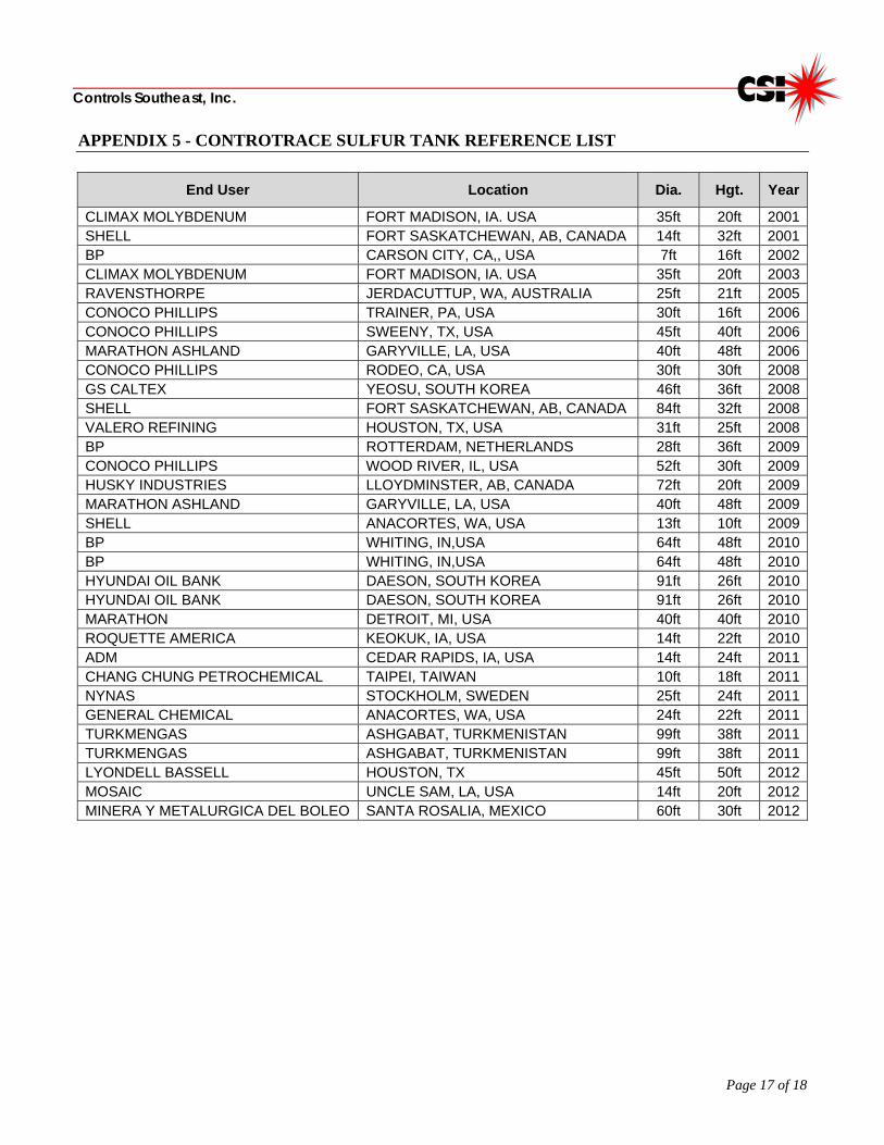
APPENDIX 5 - CONTROTRACE SULFUR TANK REFERENCE LIST
End User Location Dia. Hgt. Year
CLIMAX MOLYBDENUM FORT MADISON, IA. USA 35ft 20ft 2001SHELL FORT SASKATCHEWAN, AB, CANADA 14ft 32ft 2001BP CARSON CITY, CA,, USA 7ft 16ft 2002CLIMAX MOLYBDENUM FORT MADISON, IA. USA 35ft 20ft 2003RAVENSTHORPE JERDACUTTUP, WA, AUSTRALIA 25ft 21ft 2005CONOCO PHILLIPS TRAINER, PA, USA 30ft 16ft 2006CONOCO PHILLIPS SWEENY, TX, USA 45ft 40ft 2006MARATHON ASHLAND GARYVILLE, LA, USA 40ft 48ft 2006CONOCO PHILLIPS RODEO, CA, USA 30ft 30ft 2008GS CALTEX YEOSU, SOUTH KOREA 46ft 36ft 2008SHELL FORT SASKATCHEWAN, AB, CANADA 84ft 32ft 2008VALERO REFINING HOUSTON, TX, USA 31ft 25ft 2008BP ROTTERDAM, NETHERLANDS 28ft 36ft 2009CONOCO PHILLIPS WOOD RIVER, IL, USA 52ft 30ft 2009HUSKY INDUSTRIES LLOYDMINSTER, AB, CANADA 72ft 20ft 2009MARATHON ASHLAND GARYVILLE, LA, USA 40ft 48ft 2009SHELL ANACORTES, WA, USA 13ft 10ft 2009BP WHITING, IN,USA 64ft 48ft 2010BP WHITING, IN,USA 64ft 48ft 2010HYUNDAI OIL BANK DAESON, SOUTH KOREA 91ft 26ft 2010HYUNDAI OIL BANK DAESON, SOUTH KOREA 91ft 26ft 2010MARATHON DETROIT, MI, USA 40ft 40ft 2010ROQUETTE AMERICA KEOKUK, IA, USA 14ft 22ft 2010ADM CEDAR RAPIDS, IA, USA 14ft 24ft 2011CHANG CHUNG PETROCHEMICAL TAIPEI, TAIWAN 10ft 18ft 2011NYNAS STOCKHOLM, SWEDEN 25ft 24ft 2011GENERAL CHEMICAL ANACORTES, WA, USA 24ft 22ft 2011TURKMENGAS ASHGABAT, TURKMENISTAN 99ft 38ft 2011TURKMENGAS ASHGABAT, TURKMENISTAN 99ft 38ft 2011LYONDELL BASSELL HOUSTON, TX 45ft 50ft 2012MOSAIC UNCLE SAM, LA, USA 14ft 20ft 2012MINERA Y METALURGICA DEL BOLEO SANTA ROSALIA, MEXICO 60ft 30ft 2012
Page 18 of 18
Controls Southeast, Inc.
APPENDIX 6 – SAMPLE TANK HEATING SYSTEM INSTALLATION DRAWINGS


![testbankplus.com · 2-1-2 [HM] Steam enters an insulated tank through a valve. At a given instant, the mass of steam in the tank is found to be 10 kg, and the conditions at the inlet](https://static.documents.pub/doc/80x56/5f69456969bd8f67a3615da2/2-1-2-hm-steam-enters-an-insulated-tank-through-a-valve-at-a-given-instant-the.jpg)


