+ All Categories
Home > Documents > Sulfur Tolerant Liquid Fuel Reformer Library/Research/Coal/energy systems... · Sulfur Tolerant...

Sulfur Tolerant Liquid Fuel Reformer Library/Research/Coal/energy systems... · Sulfur Tolerant...

Date post: 04-Sep-2018
Category:
Upload: phamanh
View: 218 times
Download: 0 times
Share this document with a friend
30
Sulfur Tolerant Liquid Fuel Reformer S. Elangovan, Joseph Hartvigsen, Piotr Czernichowski (Ceramatec) Albin Czernichowski (ECP, France) 2425 South 900 West Salt Lake City, UT 84119-1517 SECA Core Technology Program Workshop Session: Balance of Plant Lakewood, CO October 27, 2005
Transcript

Sulfur Tolerant Liquid Fuel Reformer

S. Elangovan, Joseph Hartvigsen, Piotr Czernichowski (Ceramatec)Albin Czernichowski (ECP, France)

2425 South 900 WestSalt Lake City, UT 84119-1517

SECA Core Technology Program WorkshopSession: Balance of Plant

Lakewood, COOctober 27, 2005

2

Liquid Fuel Advantage

Energy DensityJP-8 43 MJ/kg, 0.76 to 0.84 kg/literDiesel 42 MJ/kg, 0.86 kg/literHydrogen at 680 bar (10,000 psi, 23100’ head) Z=1.43

4.35 MJ/liter (min. work of compression is 10-12% of LHV)

StorabilityNon-pressurized (tank cost & energy release issues)No boil-off, e.g. LNG or LH2

AvailabilityHighly developed infrastructureOnboard as road engine fuel

Fuel Choice

3

Military, Commercial and Consumer APU Markets

Class A Motor home Silent APU

Class 8 Truck Hotel PowerEliminate Road Engine Idling

Silent Mobile Electric Power

Applications

4

Obstacles to Use of Liquid FuelsSulfur

Poisons steam reforming catalystsCorrosive effect on system BOP

Aromatics, Alkenes, Alkynes, and Alicyclic hydrocarbons

Hydrogen lean mixtures, empirical formula CH2-δ

Prone to soot and coke formationDeactivation of steam reforming catalystsOperational problems to POx, CPOx, ATR, etc.

VaporizationFinal Boiling Point near thermal decomposition T

Challenges

5

The SOFC Advantage in Heavy Fuel Applications

High Operating Temperature& Oxygen Ion Conducting Electrolyte

=> Fuel Flexibility

CO as a fuel not a poisonOn anode reformation of hydrocarbon slipBetter sulfur toleranceNo thermodynamic penalty for nitrogen dilution

Ratio of pH2O / pH2 unaffected by fuel diluents Reversible Driving Potential:

Erev = EN0 T( )+

RTnF

ln pH 2O

pH 2 pO2

⎝ ⎜ ⎜

⎠ ⎟ ⎟

SOFC Benefits

6

SOFC Utilization of CO, Light HC

Fuel Feed: H2, H2O, CO, CO2, CH4

O= flux

Air Flow

CO, CO2

H2, H2O

CO, CO2

H2, H2O }Shift CO, CO2

H2, H2O{CO, CO2

H2, H2O

Reforming Reaction

CH4 + H2O <= Ni Catalyst => CO + 3H2

Shift Reaction

CO + H2O <==> CO2 + H2

O= flux

Air Flow

CO, CO2

H2, H2O

CO, CO2

H2, H2O

CO, CO2

H2, H2O+ HC

Ni Cermet Anode H2O

SOFC Benefits

Reformer Description

Operating PrincipleFeatures & Benefits

8

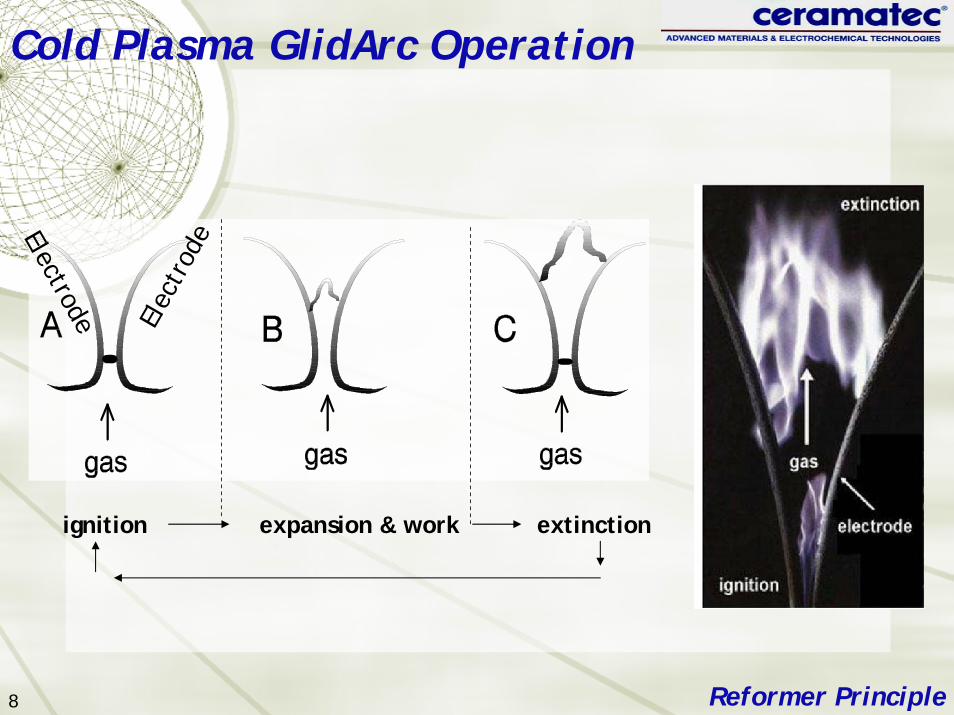
Cold Plasma GlidArc Operation

ignition expansion & work extinction

Electrode Elec

trod

e

Reformer Principle

9

Cold Plasma Reformer Features

Sulfur insensitiveNo reformation catalyst

Unaffected by SulfurNo deactivation over time

Fuel flexibilityLight to heavy hydrocarbons

Variable operating temperature (set by equilibrium thermodynamics)

700 - 900oC typical — matching SOFC operation window

Reformer Benefits

10

Cold Plasma Reformer

Very high reaction zone activityCompact reformer sizeSoot free operation

Low power requirement for non-thermal plasma

2% of fuel feed rate heating value4% of generated power (at 50% FC efficiency)8% of heat of reformation60 - 80oC reformate sensible temperature rise

Reformer Features

11

GlidArc Liquid Fuel Reformer5 kWt fuel rate, 0.6 liter, Atmospheric Pressure

Reformer

Height 12”OD: 4.5”

JP-8 Reformation

Air Force SBIR Phase II

13

JP-8 Analysis

14

Reformate Compositional Stability

0

10

20

30

40

50

60

0 4 8 12 16 20Run time (hours)

CO

H2

H2OCO2

N2

CO + H2

Fuel: JP-8

15

Reformate Hydrocarbon Slip

0.0

0.5

1.0

1.5

2.0

2.5

3.0

0 4 8 12 16 20Run Time (hours)

CH4

C2H4

C2H6, C2H2

Fuel: JP-8

Commercial Diesel(non-desulfurized)

Air Force SBIR Phase IICeramatec IR&D

17

Long-term Operation

Continuous operationReformation: 100 hoursIncluding hot stand by: 250 hours

0

200

400

600

800

1000

1200

0 50 100 150 200 250 300 350 400

Elapsed Time (hours)

Reformation Zone

Thermal Mass

Air Preheat

Reformer Exit

Fuel: Commercial diesel

18

Reformer Start-up Time

Manual Control30 minutes to temperature60 minutes to steady state

0

200

400

600

800

1000

1200

0 20 40 60 80 100

Elapsed Time ( Min )

Reformation Zone

Thermal Mass

Air Preheat

Reformer Exit

Fuel: Commercial diesel

NATO F-76

Navy SBIR Phase I

20

F-76 Specification

MIL-PRF-16884K Hydrogen content (wt% min) 12.5%Sulfur content (wt% max) 1%

Fuel: F-76

21

High Sulfur Fuel Reformate

Fuel: F-76

H2

CO

H2+CO

CO2

N2

0

10

20

30

40

50

60

70

Volu

me

Perc

ent

CH4

C2H4

C2H6

C2H20.0

1.0

2.0

3.0

4.0

5.0

Vol

ume

Perc

ent

22

SOFC Test of JP-8 Reformate Slip Stream

Stack Test

23

SOFC Stack on JP-8 Reformate

Stack Test

0

10

20

30

40

50

60

70

80

100 125 150 175 200 225 250 275 300

Time (Hrs)

Hydrogen Hydrogen

JP-8 Reformate(desulfurized)

DAQlock-up

JP-8 Reformate(desulfurized)

Hydrogen

24

Stack Test Results Three tests conducted

Two 10-cell stacksPair of 11-cell stacks

Performance comparable to hydrogen baseline

Power output difference correlates with reformate Nernst potential depressionSome cooling of stack due to presence of hydrocarbon in the reformate

Soot free operation demonstratedNo soot found in fuel manifolds or electrodes

Stack Test

25

Post Test AppearanceFuel Electrode

Stack Test

26

Button Cell Test on Diesel Reformatenon-desulfurized raw reformate

0.0

0.2

0.4

0.6

0.8

1.0

0 0.2 0.4 0.6 0.8 1

Current Density (A/cm2)

Cell

Volt

age

(V)

0

0.1

0.2

0.3

0.4

0.5

Pow

er D

ensi

ty (

W/c

m2 )

cell no. 73Fuel: diesel reformate180um Sc-doped zirconia electrolyteTemp: 850°C

ASR=0.67 ohm-cm2

Commercial Diesel / Button Cell

Cell ASR similar to H2/H2O fuel

27

On JP-8 ReformateLower Nernst potential (~ 100 mV)Presence of H2S (~ 50 ppm)Cell cooling from methane reformation (~2% methane)

Button Cell Test on JP-8 ReformateNon-desulfurized raw reformate

JP8CELL10245Temp: 800°C

Cell Voltage: 0.7 Velectrolyte: ~180 micron ScSZ

0.00

0.10

0.20

0.30

0.40

0.50

0.60

0 2 4 6 8Time (Hours)

Curr

ent

Den

sity

(A/

cm2 )

Hydrogen - 3% H2O Hydrogen - 3% H2O

Raw JP-8 Reformate(no desulfurization)

28

Work in ProgressProcess Optimization

Effect of fuel equivalence ratio (φ)

Size scale up

20 kWt ReformerHeight: 12”

OD: 7”5 kWt Reformer

Height: 12”OD: 4.5”

Present focus

29

Remaining ChallengesProcess optimization

Mapping reformate composition as a function of temperature, fuel/oxidant ratio, and residence time

SOFC integration testReformer re-design in progress (Air Force)

Start up time reductionUninterrupted extended operationTurn down

30

AcknowledgementsUS Air Force

Hill Air Force Base, Air Logistics CenterJoe BurnsPhase II SBIR Grant No. F42650-03-P-2750

US NavyNAVSEA, PhiladelphiaBrian Prew and Don HoffmanPhase I SBIR Grant No. N655538-05-M-0145

Ceramatec, Inc.IR&D Funding


Recommended