Page 1
SSC-300
SUMMARY OFNONDESTRUCTIVE INSPECTION
STANDARDS FOR HEAVYSECTION CASTINGS, FORGINGS,
AND WELDMENTS
Thisdocumenthasbeenapprovedforpublicreleaseandsale;its
distributionisunlimited.
SHIP STRUCTURE COMMl~EE
1981
Page 2
SHIP STRUCTW+S COMMITTEE
The SHIP STRUCTUS2 COM4TTTF.Eis constituted to prosecute a researchprogram to improve the hull Wzwcurea of ships and other mmine !jCruccures byan extension OE knowledge pertaining co design, mcerials and methods a fC’mlszr”ctiorl.
RADM H. 8. BELL [Chaimkml Mr. J. GHOSSChief, Offb of r%mc+wnt DeputyA8ei8tmt &5n!ki8tmto?
Marinesafe% for Conmms+al Davelopm.tL!”s. Croat Glnzl%? Maritim Adtnimktzwtim
Mr. P. M. Pusmio <Mr.P. Mci?C>N4LDDeputyOirztor, Rul1 Gmzp Chief,Brmuh of OffshoreM!xl 1 sea Sy*tima Cm?nlnd IW ld Cpenzticma
Us. CmOlopicd .%-my
Mr. U. N. LS4.WAN m. c. J. kmlsslwsFk? Prsaidmlt Sn@rwr OfficerAm2.i.cma-m of shipphg Mi titary Sealij%Cor7mmd
CDR i“.5. ROEIESOJi,U.S.Caast Guard (.%cretaq)
sUP STSCUCTOR3SL5COMKITTSE
‘HI. SHIP STWJCTDRS SUBCOMWTTEE acts for the ship $ltrwx.ru rmmictmon technical matters by providing technical coordination Em ohm dscp,rmimeimof goals a.ad objectives of the pmsram, and by evaluating and tncm-precingche results in cem of %cnactur.ql design, .mstrucic.m and operation.
U.S. COMT GUARLI lULETAF!T SSALZST CQIN4AUD
MET R. L. ZROh77(7DRJ. C. CARD
CUR J. A. SXNL4L.JR.CDR k’.M. SIM2SOW,JR.
VAt’AL SEA STSIT3?S COMWAND
k.. R. K. CH17J
hi..J. E. O’m.im.&. V. C. SAA7LWAS?GMr. R. F. SwAmLCOR D. Ii.h7L?l?OOZ
Us. CSOLCGICAL Ww?ET
I&r. R. al.G.t&TGSRSLLKJ&. J. B. @lStWRr
NATIONALACAIIE?UOF SCIENCES
m. G. AslssM% T. M. CS7AMWMS A. B. STAVOWMr. D. 3TS2T
AINNSICM? BURSAU OF SKIPPING
Or. D. LIUm. I, L. STs’m
lLUIT7UiE ADUINISCF.ATI.OK
NW. N. O. &wwRRor. u. Al.U.4CLJXMMr. F, SS’.E+OLDMr. M. v. TOuw?
INTRCWASTONALSHP slW3CTOtOLS COWRFHS
Mr. S. G. STMNaSf?,? - Liaison
slim EZSSANCE coMiwm!s -CAN IXON 6 mmz nwrrru’re
Mr. A. D. &IX? - C.idSOU/4.. R. W. ROMKE - %tiiSQm
Mr. R. R. ST,TSNE- Liaison
STATE OTNERSITY CM NEW YCNSKtWKTIHS COLLSGBIWS SOCIETT OF WAVAL AICCICITECTS
& MARINE sNGINsEF.S Or. W. R. .?OXT’XR- L1aisocI
,Hr. N. O. RAMfEA! - Liais,x U.S. COAST GVABCACADRMY
I?SLDING SRSEARCH COLNCIL LLVR R. G. WJ.u-mim- L.i.imc
i!. S . 14ERCHANTU4RIhW AC.4DEMT h. i?. &34TTAC!i.4FiYif.4- Liaisor,
h’. C.-B. U?/ - Liaison
Page 3
MemberAgencies:
UnitedStatesCoastGuardNavalSeaSystemsCommand
MilitarySealiftCommandMaritimeAdministration
UnitedStatesGeologicalSurveyAmericanBureauofsipping
*
AddressCorrespondenceto:
Secretary,ShipStructureCommitteeU.S.CoastGuardHeadquarters,(G-M/TP13)Washington,D.C.20593structureCommittee
AnInteragencyAdvisoryCommitteeDedicatedto ImprovingtheStructureofShips
SR-1255March1981
Asvesselshaveexpandedinsizeanddeadweightduringthelastfifteenyears,therehasbeena similarincreaseinthesizeofforgings,castingsandheavyweldmentsusedinvessels.Some~-xamplesofsuchcomponentsarestemandsternframes,rudderhorns,sterntubes,tailshafts,propellers,andsomeengineparts.TheShipStructureCommitteebecameawareoftheneedtodevelopquantitativeguidelinesforthenondestructiveinspectionofthesecomponents.
A projectwasinitiatedtosurveytheliteratureandwriteaninterpretativereportofthestateoftheartin thisfield.Whilevariousmethodsandpracticeswerereviewedanddiscussed,theusermuststillspecifytheacceptancelimitstomeettheintendedservice.
Theresultsoftheprojectarecontainedinthisreport.
RearAdmiral,U.S.CoastGuardChairman,ShipStructureCommittee
Page 4
TechnicalReportDocumentationPage1. Report No. 2. ~crnmcnt Acce$sion~-~ 3. Rec#plent’s Catalog No.
SSC-3004. Title and ~ubt;tlc
—L–-+-—- ‘-5. Rena, ! t)rlI-
SUMMARYOFNONDESTRUCTIVEINSPECTIONSTANDARDSk“- ‘--
DECEMBER1980FORHEAVYSECTIONCASTINGS,FORGINGS,ANDWELDMENTS‘---b.P~rform, ng OrgonazotaonCode
8. Performing Orgon,zation Report No.7. Author~s)
ROBERTA.YOUSHAWI
9. Per forrnir,g Orgonixat~on Nome and Address—
10. Work U“, t No. (T RAIS)
NavalSurfaceWeaponsCenter-WhiteOak 11Conlroct or Grant No,
SilverSpring,MD20910 NAVYZ 70099-6-7137513.Typeof Report and Per, od Covered——
12. 5pon3,yring Agency Nome cjnd AddressY
U.S.CoastGuard FINALOfficeofMerchantMarineSafetyWashington,D.C.20593 I’14. Sponsorin~ Agency Code
G-MI
15. Supplementary Notes
ShipStructureCommitteeProjectSR-1255
Codebodies,notablyASTM,haveproducedproceduralguides,standardmethods,andrecommendedpracticeswhichcanbeusedtoassureproperinspectionforthevariousmethodsofnondestructivetesting.Theseguidesandpracticesinprivateindustryhavebeenreviewedfortheirapplicabilitytoqualitycontrolofheavysteelcastings,forgings,andweldments.Acceptancecriteriaarenotsetforth,andrecommendationsarenotsuggested.Theydo,however,define levelsofqualityanddescribetheparametersgenerallyagreedtobeofsignificancewhichshouldbe a part of the contractual agreement.Theusermustquantifytheseparametersaccordingtoservicerequire-mentsandotherconsiderations.
II
17, Key WordsNondestructivetesting Ill.,stribut, o StatementD%cumen?1savailabletotheU.S.Publicforgings throughtheNationalTechnicalInformaticcastings Service,Springfield,VA22161.radiographicinspectionultra~qnicin$pctjonfmaanetlcpartlce Inspection
19. Security Classif. (of this report) 20. Security Clossif. (of this page) 21. No. 01 Pages 22. Prica
I UNCLASSIFIED I UNCLASSIFIEDI 32 IL I ~FormDOTF1700,7(8-72) Roproductihn of completed page authorized
. . .--&’L-z--
Page 5
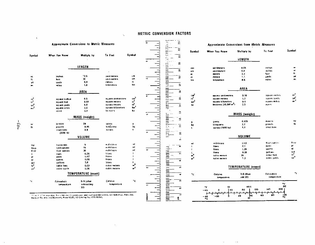
METRICCOIWERSIOBlFACTORS
ApproximateConversionstoMetricMeasrnes
Symbol WhenYouKnow Multiplyhy
d112yd2,1,,2
LENGTH
inches “2.5!eci 30qad 0.9mileg 1,6
AREA
sqmweinches 6.5squarelee! 0.09squareymds o,asquaremiIes 2.6,Ic,M 0.4
MASS [weight).
0“11CC5 20pcwbds 0.45SIIWIsons 0.9
(2000lb)VOtlJME
Iu,>s(”,ums 5I,lblcspoolls 35Itu,dG+IOCeS 30cup5 0.24p,tll5 0.47qum(s 0.95Oallmls 3.$cubiclent 0.03c~,bmyards 0,76
TEMPERATURE(exact)
Fahrenheil 5/9 talmrtcmperalurn subtracting
32)
Tofind Symbol
centimeterscenlinmwxsmeterskilmmettirs
SQ,lfiFl?cmtlnwemSu,,,,,cmcletsSW.IW.wtwssqumckilm,wlomI,,,ct,,,r.
,,,,lt,l,l,!,fi,Inliililcrs,Ih,llll,letshlerslitersIimrsIltc<scubicmelcrscubicnwlars
tmcmmh
~2n?#hmzha
rrk!!I
,,,ImIndIII!m’ma
“c
, ,+,, .,,1,, ,,..,ll,,”,.r,“ ,,,,,,,, ... .,, i , “,,.,,,,.,,”,>,,,.,,W.Jr.*1 .,,.,1 L,h!<.,,,!,,.Iwi M,*. Pd!l.Zw.U,,,I*“1w.!L0tb15.IwlM..!wnr..P,Ice*2.25,so C.lmfu+N“.c13.1W213G.
.. .-lm—..——.——.— H. .— .— .- .-. z..—.....—-. z.————.————— 5——.——.—=— 2~—-=——-.— z—————~~— 5.
.-.—.—--— .~_ ..—.- ....~. s~.- :.—_-—----.—..————. m..—..——-—~— .~————. w.————
.~-=— .~——
.=-.————— t+~_=~ ..~ ~—
Svmbnl
mcmmmkm
a?~2
km?ha
9M1
*,,III
:’m3
“c
ApproximateConversionsIromMetric
W2teriYOIIKnow Mullicilf bf
LENGTH
millinmter5 0.04cmlimelers 0.4m3ters 3.3freaers 1.1kilcmwtezs 0.6
AREA
squarecentirmicrs 0.i6squaremeters 1.2squawkiImwlcts 0.4hectares(10.002mz) 2.5
MASS(weight]
ofms 0.035ki$ogmms 2.2Imm?sI1OOOkwl 1.1
VOLUME
mill,l,lms O.OJliters .2.1Iiwrs 1.06Iit.cxs 0.26cubicrmmvrs 35cubicMci.31S 1,3
H?WPERATUREIertm)
C91siu5 9,5(!hmtemperawre add32)
Measures
10find
mdmsmcl,csb 1yard5miles
,“mitydm,
mmcrspmmd,SklnftIIHIS
orlb
Frdwenheit ‘fwnwratute
‘F‘F 32 9a6 212
-*O o 40 80i,, ,il; l,tl, l~
!20 160 2W1’ , ,
1 1 I t 1 1-40 ‘-20 o 20 40 Go #o IOu
●C 37 ●C
Page 6
Page
INTRODUCTIONOBJECTIVkANDSCOPEBACKGROUNDNONDESTRUCTIVEINSPECTION- GENERALNONDESTRUCTIVEINSPECTIONOFSTEELCASTINGSRadiographyUltrasonicMagneticParticleInspectionLiquidPenetrantInspectionMethodVisualInspection
NONDESTRUCTIVEINSPECTIONOFSTEELFORGINGSRadiographicInspectionUltrasonicInspectionMagneticParticleInspectionLiquidPenetrantInspectionVisualInspection
NONDESTRUCTIVEINSPECTIONOFTHICKWELDSRadiographyUltrasonicInspectionMagneticParticleInspectionVisualInspection
SUMMARYANDCONCLUSIONS
1112228101112151515171813181820212226
TABLES
Table Page
Page 7
ILLUSTRATIONS
m1
2
3
4
5
6
7
8
9
10
11
12
13
14
IllustrationofGasPorosity,CategoryA,SeverityLevel5 - fromASTME-186,ReferenceRadiographsforSteelCastings.
IllustrationofSandandSlagInclusions,CategoryB,SeverityLevel5 - fromASTME-186,ReferenceRadiographsforSteelCastings.
IllustrationofShrinkage,Type1,CategoryC,SeverityLevel5 - fromASTME-186,ReferenceRadiographsforSteelCastings.
IllustrationofShrinkage,Type2,CategoryC,SeverityLevel5 - fromASTME-186,ReferenceRadiographsforSteelCastings.
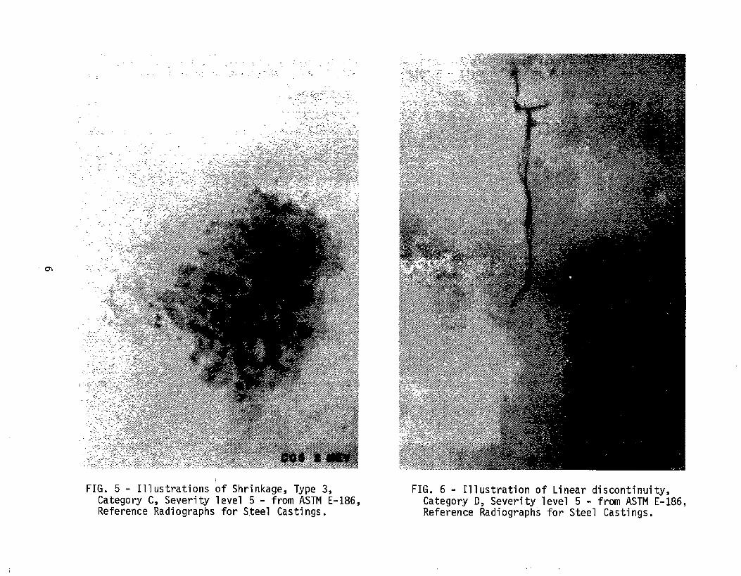
IllustrationofShrinkage,Type3,CategoryC,SeverityLevel5 - fromASTME-186,ReferenceRadiographsforSteelCastings.
IllustrationofLinearDiscontinuity,CategoryD,SeverityLevel5 - fromASTME-186,ReferenceRadiographsforSteelCastings.
IllustrationofInserts,Type1,CategoryE,SeverityLevel5 - fromASTME-186,ReferenceRadiographsforSteelCastings.
IllustrationofInserts,’Type2?CategoryE,SeverityLevel5 - fromASTME-186,ReferenceRadiographsforSteelCastings.
Wrinkles,Laps,Folds,andColdshutsfromQualityStandardforSteelCastingsS-P-55(VisualMethod).
AverageStrengthofCastTensileBarsforVariousDegreesofShrinkageSeverity.
EffectofShrinkageon“PlateBendingFatigueofCastSectionsofNormalizedandTempered8630Ni-Cr-MoSteel.
BendingFatigureforNormalizedandTempered8630CastSteelContainingSurfaceQiscontinuities.
TorsionFatigueforNormalizedandTempered8630CastSteelContainingSurfaceDiscontinutiies.
E d Li iti P l tiT i T ti f
E%E4
4
5
5
6
6
7
7
13
22
22
23
23
23
Page 8
INTRODUCTION
TheRulesForBuildingandClassifyingSteelVessels(MericanBureauofShipping)requiresoftheshipbuilderthathullsteelcastingsandforgingsbeinspectedandfoundfreeofinjuriousdefects.Thisistobedonetothesatisfactionoftheattendantsurveyor,andtheremaybedifferencesinac&eptancecriteriabetweenshipyards.Intheinterestsofuniformityandalsoasa helpincontractuallyspecifyingdesiredcastingquality,theShipStructuresCommitteehascontractedwiththeNavalSurfaceWeaponsCentertopreparea state-of-the-artreportonprocedureswherebycastingandforgingqualitycanbecontrolled.
Inaddition,incorporatingtheselargecastingsandforgingsintothehullstructureinvolvesweldingthicknesseswellinexcessofordinaryhullwelds.Thisreportalsoconsidersproceduresforinspectingandcontrollingthequalityofthesewelds.
OBJECTIVEANDSCOPE
Theobjectiveofthistaskhasbeentodeterminethepresentstate-of-the-artforcontrollingthequalityoflargesteelcastings,forgingsandthickweldsusingnondestructiveinspectiontechniques.Thishasbeendonebya reviewofspecificationsandstandardssetforthbycodebodiesandasurveyofrepresentativemanufacturers.
BACKGROUND
AccordingtotheRulesFor‘Bui’ldi’nqandClassifyingSteelVesselssetforthbytheAmericanBureauofShipping,“AllcastingsaretobeinspectedbytheSurveyorsafterfinalheattreatmentandthoroughcleaningandtheyshallbefoundfreefrominjuriousdefects.”Minordefectsmayberepairedatthediscretionofthefoundry.Majordefectsmayberepairedwiththeapprovaloftheattendantsurveyor.
Repairisdonebychippingorgrindingtosoundmetalandthenreweldingbyanapprovedprocedure.Tnthecaseofmajordiscontinuityremoval,verificationofcompleteremovalisaccomplishedbysubjectingtheexcavationtoeitherradiographicormagneticparticleinspection.
TheRulesForBuildingandClassifyingSteelVesselsalsorequirethathullsteelforgingsbeinspectedbythesurveyorafterfinalheattreatmentandbefoundfreefrominjuriousd f i i
Page 9
NONDESTRUCTIVEINSPECTION- GENERAL
Inregardtomaterialevaluationusingnondestructiveinspectiontechniques,therearefiveordinarymethods-Radiography,Ultrasonics,MagneticParticle,LiquidPenetraht,andVisualInspection.
Ofthese,onlyradiographyorultrasonicinspectioncanprovideproofofinternalintegrityandtheyareconsideredtheprimarymethods.However,visualinspectionandthemagneticparticlemethodareeasytoapplyandcanbeavaluableadjuncttotheotherprimarymethods.Inparticular,visualstandardscanbeusedtospecifya requiredsurfacetextureandmagneticparticleinspectioncanbeusedtoinspectforcracksnearthesurface.Also,whendefectsarefoundbeneaththesurfacebyeitherradiographyorultrasonics,andaretoberemovedbychippingorgrinding,magneticparticleinspectioncanbeusedtoverifycompleteremovalofthosedefects.
Liquidpenetrantisnotmuchusedonlargesteelpiecesbecausemagneticparticleinspectionisusuallysuperiorfordiscontinuitydetectionandismuchfastertodo. However,itcanbedoneanditsusewillbeconsidered.
NONDESTRUCTIVEINSPECTIONOFSTEELCASTINGS
Radiography.Controllingthequalityofsteelcastingsusingradiographicinspectionrequiresfirstofalla meansforensuringthattheinspectionisdoneproperly.Thiscanbeaccomplishedbyspecifyinggoodpracticeaccording~hi:STME-94,RecommendedPracticeforRadiographicTesting.documentisprimarilyeducationalandconsidersthe“preferred”parametersofindustrialradiographywithoutdiscussingtheprinciplesofphysicsuponwhichthesearebased.Bothx-rayandgamma-rayradiationsourcesarereviewed.Neitherinterpretationnoracceptancecriteriaarecovered- thesearelefttocontractualagreement.Itshouldbenofed,however,thatunlessotherwisespecifieda radiographicqualitylevelof2%(.2-2T)isimplied.
SatisfactoryfilmqualitycanbecontrolledwithASTME-142,ControllingQualityofRadi’ograp”hic”Testing.Thismethodstandardizesthetechniquesforcontrollingthereliabilityorqualityofradiographicimages.Unlessother-wisespecified,a minimum2%(2-2T)qualitylevelisrequired.
Theimagequalityindicator(penetrameter)isdefinedand
Page 10
Objectswithvaryingthicknesscanbeexpectedtoresultinradiographsexhibitingdensityvariation.Permissiblelimitsforonepenetrameteraredefinedas-15to+30%.Variationsinexcessofthisrequiretwopenetrametersplacedatfilmdensityextremestoqualifytheareabetween.
ThetypesofcastingdiscontinuitiesthatmayberevealedbyradiographicinspectionareillustratedingradedseriesinreferenceradiographspublishedbyASTMaslistedbelow:
ASTME-186ReferenceRadiographsforSteelCastings(2-41/2”section)
CategoryA - GasPorosity- Severitylevels 1-5B - SandandSlagInclusionslevels 1-5c- Shrinkage
Type1 - Severitylevels 1-52 - Severitylevels 1-53 - Severitylevels 1-5
D- Lineardiscontinuityseveritylevel1 - 5E - Inserts
Type1 - Severitylevels 1-52 - Severitylevels 1-5
Figures1 - 8 arepaperprintswhichillustratethemostseverelevelforeachofthesediscontinuitytypes.Thesearepresentedforillustrativepurposesonlyandmaynotbeusedasacceptancecriteria.
TheASTME-186seriesisavailableforthreeconditionsofradiographicexposure:GammaRays(Co60,Ra),1 - 2MeVX-rays,and10- 24MeVX-rays.
ASTME-280ReferenceRadiographsforSteelCastings(41/2- 12”sections)
CategoryA -B -c-
D -E -
GasPorosity- Severitylevels 1-5SandandSlagInclusionslevels 1-5ShrinkageType1 - Severitylevels 1-5
2 - Severitylevels 1-53 - Severitylevels 1-5
Hottears& cracksseveritylevel 1 - 5InsertsType1 - Severitylevels 1-5
2‘-Severitylevels 1-5TheE-280seriesisavailablefor
radiographicexposure:GammaRays(Co6i~oR~~~d~~~o~~~f24MeVX-rays.
3
Page 11
-P
FIG.1- IllustrationofGasPorosity,CategoryA,Severitylevel5- fromASTME-186,ReferenceRadiographsforSteelCastings
FIG.2- IllustrationofSandandSlagInclusions,CategoryB,Severitylevel5 - fromASTME-186,ReferenceRadiographsforSteelCastings.
,
Page 12
. . _—_=.-
.—
.—
-. ——
.—.
u-l
FIG.3- IllustrationofShrinkage,Type1,CategoryC,Severitylevel5 - fromASTME-186,ReferenceRadiographsforSteelCastings.
FIG.4- IllustrationofShrinkage,Type2,CategoryC,Severitylevel5- fromASTME-186,ReferenceRadiographsforSteelCastings.
Page 13
“m
FIG.5- IllustrationsofShrinkage,Type3,CategoryC,Severitylevel5- fromASTME-186,ReferenceRadiographsforS,teelCastings.
FIG.6 - IllustrationofLineardiscontinuity,CategoryD,Severitylevel5- fromASTME-186,ReferenceRadiographsforSteelCastings.
Page 14
.-.-_—- —-.?-.=.l::----—,----_-.-=.-
-.-.-.
--—
.-..-.
EA5 2MEV
.-
.
f.:
. .
EB5 2 MIEV
FIG.7- IllustrationofInserts,Type1,CategoryE, FIG.8- IllustrationofInserts,Type2,CategorySeveritylevel5 - fromASTME-186,Reference E,Severitylevel5 - fromASTME-185,ReferenceRadiographsforSteelCastings. RadiographsforSteelCastings.
Page 15
Ifreferenceradiographsaretobeusedasa meansforcontrollingcastingquality,itmustberealizedthattheyarenotinthemselvesa standard.Theirusemustbesupplementedbycontractualspecificationssettingforththemaximumacceptablelevelofseverityforeacht~e ofdiscontinuityillustrated.Inaddition,thisshouldbedoneforeachsectionofthecastingrequiringradiographicinspectionandforwhichdifferentservicerequirementsarerecognized.
Theseveritylevelsforthetypesofdiscontinuitiesillustratedarenotequivalent.AcceptancecriteriabaseduponASTMReferenceRadiographs“shouldreflectseparateconsiderationforeachtype.Forexample,referencingE-186,maximumacceptablediscontinuitiesregardinga specificpartofthecastingareasfollows:
CategoryA -B -c-
D-E -
GasPorosity- Severitylevel 4SandandSlagInclusionslevel 3ShrinkageType.1 - Severitylevel 1
2 - Severitylevel 23 - Severitylevel 2
Lineardiscontinuity noneInsertsType1 - Severitylevel 4
2 - Severitylevel 4Itshouldalsobenotedthatthesizeofthereference
radiographisinherentlya partoftheacceptancecriteria.Asforexample:Usinga radiograph5“x 7“,thenno5“x 7“areaofthecastingradiographscanexhibitdiscontinuitiesinexcessofthatillustratedinthespecifiedmaximumlevelseverityforthatdiscontinuitytype.
UltrasonicInspection.UltrasonicinspectionisbeingusedtocontrolthequalityofsteelcastingsinboththeUnitedStatesandoverseas.Longrecognizedas a #aluablesupplementarytooltoradiographicinspection,manyfoundriesandtheircustomersnowuseultrasonicinspectionasthesolenondestructivetestingmethodfordeterminingsubsurfacecastingintegrity.
Whentheultrasonicmethodistobeusedasa primarymethodforinspectingsteelcastings,procedurecanbecontrolledbyspecifyingASTMA-609,LoqqitudinalBeamUltK,asOnicznS:p@c,tionofCarbon;andLoWALI’dy”’Slie”e”l‘Castings.-—
Thisspecificationmaybeused’contractuallytoestablisha requiredqualitylevel.Itmustbestatedifthequalitylevelistobefortheentirecastingoronlyforcertainsections.
8
Page 16
Examinationisbytheultrasonicpulse-echomethodusingthelongitudinalbeam(straight)technique.Requirementsaresetforthregardingtheultrasonicinstrument.Itmustbecapableofgeneratingfrequenciesbetween1 and5MHZandhaveverticallinearitywithin+ 5%for75%ofthescreenheight.A signalattenuatoraccura~etowithin10%isalsorequired.Primaryinspectionistobedone“usingeitheroneinchsquareoroneinchdiametertransducers-
Referenceblockscontainingflatbottomedholesareusedtoestablishtheinstrumentsensitivity.Thediameteroftheholeisheldconstantat1/4inchbuttheblockscomprisingthesetvaryinlengthfrom1 - 10incheswithprovisionfortestingthicknessesgreaterthan10inches.
Thepersonnelperformingtheultrasonicexaminationmustbequalified,andgeneralguidanceinthisregardisprovided.QualificationtoASNTTC-lAissuggestedbutnotrequired;but,a recordmustbekeptof‘personnelqualification.
Anyheattreatmentformechanicalpropertiesmustbedonebeforeultrasonicexamination.Thereisa requirementforthecleaningofthecastingsurface.
Theinspectionofthecastingistobedoneata ratenottoexceedsixinchespersecondandthetransducerpassesmustoverlap.
Insomecases,itmaybeadvantageousornecessarytouseananglebeamtechnique.ProperprocedurecanbespecifiedusingASTME-587-76,.Standard“RecommendedPracticefor”UltrasonicAngleBeamExaminationByThe”.Cdn~aGtiMe’thod.Thisrecommendedpracticeconsiderstheultrasonicexaminationofmaterialsatangularincidence.Fourtypesofwavesareconsidered:Longitudinal,Shear,Rayleigh~andLamb.Thephysicsandmethodsofgeneratingeachtypeofwavearesetforth.Inaddition,attentionisgiventopossibletestcomplicationswhichmightariseduetothecoexistenceoftwodifferenttypesofwavesundercertainconditions.
A calibrationprocedureissuggestedutilizingthereflectionfroma side-drilledhole.Thediameteroftheholeisnotspecifiedandsomustbedescribedcontractually.Inregardtoacceptancecriteria,itissi?ggestedthatadvanceagreementbemaderegardinginterpretationanda rejectionlevel.
Inadditiontothesedocumentsproducedthroughcodebodies,somefoundrieshavecreatedultrasonicinspectionproceduresdesignedtoreplaceradiographicinspectionofa statedseveritylevel- usuallywitheconomicadvantage.Theseproceduresareinvariablyproprietaryand,therefore,notgenerally available
exceptona case-by-casebasis.
9
Page 17
Castingsareoftencomplexinconfigurationandcompleteinspectiondoneusingultrasonicsmayrequireinnovativetechniques.Valuableguidanceinthisregardhasbeenprovidedinthefollowingpublicationsbytechnicalsocieties:UltrasonicTestingofSteelCastings,SteelFoundersSocietyofAmerica,RockyRiver,Ohio,June,1976;AtIdsofSomeSteelCastingFlawsasshownbyNon-DestructiveTesting,SteelCastingsResearchandTradeAssociation,Sheffield,England,1968.
MagneticParticleInspection.Steelcastingsmaybeinspectedwiththemagneticparticlemethod.ProperprocedurecanbeassuredforwetmethodusingASTM E-138,‘Wet.MagneticParticleInsnection-.Thisstandardmethod,applicabl~toallferromagneticmaterials,presentstechniquesforthewetmethodofmagneticparticleinspection.Itdoesnotpresentorsuggeststandardsfortheevaluationofindicationsobtained.Itisrecognizedthoughthatevaluationisnecessaryandtherecom-mendationismadethatcontractualagreementincludetheacceptancecriteria.Inaddition,itfurtherrecommendsthatthecontractspecifytheareatobeinspected,thetypeofmagnetizingcurrent(ACorDC),thedirectionofthemagneticfield,howmany“shots”aretobeused,(longitudinal,
themethodofMagnetizationcircular,over-allorlocal),themagnetization
currentorampereturnstobeusedoneach“shot’tandthesequenceofoperation(continuousorresidual). Itisstatedthat“Allofthesetechniquescausevariationsinresultsandmustbestandardizedifreproducibleresultsaretobeobtaineduponwhichacceptancestandardsaretobebased.”Thebalanceofthisstandardmethodsetsforththeprinciplesofgoodpractice.
Ifthedrymethodistobeused,theprocedurecanbecontrolledusingASTME-109,DryPowderMagneticParticleInspection.Thismethodconsidersallofthemagnetizingproceduresuse= thewetmethodandalsoincludes,inaddition~‘magnetizationusingelectricalprods.Aswiththewetmethod,acceptancecriteriaisneithersetforthnorsuggested.Fudther,aswiththewetmethod,thisstandardrequiresa specificagr~ementbetweenthecontracturalpartieswhichaccuratelydefinesindicationsconsideredacceptableandthoseconsideredunacceptable- thisinregardtotype,locationanddirection.
Thedocumentreviewstheequipment,materialsandprocedurerelatedtogoodpractice.Specificguidanceispresentedformagnetizingtechnique,directionofmagnetizationandthesequenceofoperations.Therequirementsforadequateelectricalcurrentaresetforthina tablewhichconsidersbothprodspacingandsectionthickness.
Appendix1ofASTME-109presentsAdditionalProcedures,whichincludesdirectandindirectmethodsforaccomplishingover-allmagnetization,techniquesrelatingtolongitudinalmagnet-ization,theuseofalternatingcurrent,theutilizationofresidualmagnetizationandproceduresfordemagnetization.
NOTE: ASTME-109andE-138havebeenddetedandr@pla=dWM~E-709.
10
Page 18
Appendix2 ofASTME-109includesTypicalIndications.Thisisa setofreferencephotographsillustratingindica-tionsoncastings,welds,rolledorforgedmaterialandnonrelevantindications.
Difficultiesarefrequentlyencounteredinattemptstocontractuallyspecifyacceptableorunacceptableconditionsasrevealedbymagneticparticleinspection.ThishaspromptedASTMtoassemblea setofreferencephotographstoprovideassistanceinthisregard.Thesearepublishedas: ASTME-251-63,Refer.enc.e,Ph.otoqraphSForMagneticparticleIndicationsan,F,errousCast~n.g$.Thesereferencephotographsareapplicabletoferromagneticcastingsinspectedbythedrypowdermagneticparticlemethod.Bycomparingthediscontinuitiesrevealedinmagneticparticleinspectionwiththesereferencephotographs,specificationsand/oracceptancecriteriamaybeestablished.Itisnecessarytocontractuallystatethelimitingdegreeofseverityandthelocationstobeinspected.
Fivetypesofcastingdiscontinuitiesareconsidered.Theseare:Lineardiscontinuities- fivelevelsofseverity,threeexampleseach;Shrinkage- fivelevelsofseverity,oneexampleeach;Inclusions- fivelevelsofseverity,oneexampleeach;Internalchillsandchaplets- fivelevelsofseverity,oneexampleeach;Porosity- twoexamples.
Inaddition,referencephotoqr.aphsareincludedforweldswhichmaybeincorporatedintothecasting:Oneexampleeachofweldporosity,incompletepenetration,undercutting,inclusionsintheweld~andcratercracking.
Fiveexamplesarepresentedoffalseindicationsandfiveexamplesareincludedofmagneticanomalies.
Itiscalledtothe‘usersattentionthatthereisnocorrelationorequivalencybetweenthelevelsofseverityofthevariousdiscontinuities.
LiquidPenetrantInspectionMethod.Ifliquidpenetrantinspectionistobeusedtoinspectsteelcastings,properproceduremaybeensuredthroughASTME-165,~>.quidPenetrantInspection-’‘Method.Thisisa standardrecommendedpracticeapplicabletononporousmetallicmaterialssuitedtothedetectionofdiscontinuitieswhichareopentothesurface,suchascracks,seams,laps,coldshuts,laminationsandlackoffusion.
Standardsforevaluatingindicationsareneitherindicatednorsuggested.Therefore,contractualagreementmustincludespecificationsdefiningthetype,size,location,anddirectionofindicationsconsideredacceptableandunacceptable.Further,a “strongrecommendation”ismadethatthespecifictechniquesbea partoftheagreement.
Fluorescentandvisibleliquidmethodsareconsidered.Foreachofthese,threesubgroupsarerecognized:water-washable,post-emulsifiable,andsolvent–removable.Proceduresrelatingtogoodpracticearesetforthforeach.
‘111
Page 19
A cautionarynoteisincludedregardingthesulfurandchlorinecontentofthepenetrantinspectionmaterials.Insomecases,thepartstestedmaybeadverselyaffected.Limitationsonthesesubstancesmaybeanessentialpartofthecontractualagreement.
Thedescriptionofindicationsasrevealedbypenetrantinspectioncanbedifficult.Someassistanceisavailablethr~ughreferencephotographsinASTME-433,LiquidpenetrantInspection,Thisstandardisa setofreferencephotographsofsurfacediscontinuitiesrevealedbyliquidpenetrantinspection.Althoughnoattempthasbeenmadetoestablishlimitsofacceptability,itisstatedthatthesephotographsmaybeusedasa referenceinspecificationsoracceptancestandards.Suchusemustbesupplementedbylimitationsonactualdiscontinuitylengthandthenumberofindicationsacceptableperunitarea.
Thereferencephotographsrecognizea distinctionbetweenindicationsforwhichneitherofthemeasurabledimensionsisthreetimesgreaterthantheotherandindicationsforwhichthisistrue.Foreachcategoryfoursubgroupsarepresented:Single,MultipleUnaligned,MultipleAlignedandtheIntersectionofsurfacessuchascornersorfillets.
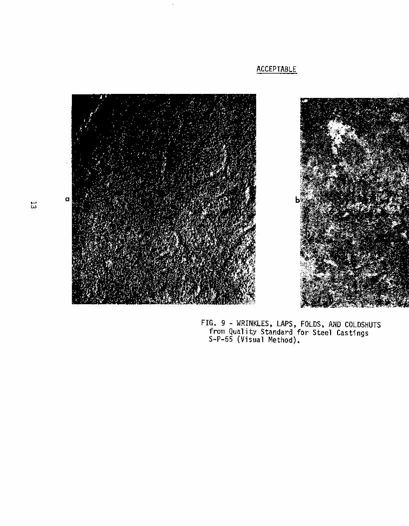
VisualInspection.TheManufacturersStandardizationSocietyoftheValveandFittingsIndustryhavedevelopedvisualstand-ardsforevaluatingsteelcastings:s-P-55,1971edition(reaffirmed1975),[email protected] ”ForValves,FlanqesandFittinqsandOtherPipinqComponents(VisualMethod).Figure9whit? illustratesthesurfaceconditionswrinkles,laps~andcoldshuts,isanexampleofthevisualstandardssetforthinthisdocument.
Thesestandardsillustratesteelcastingsurfaceconditionsthatmaybeevaluatedvisually.Twelvecategoriesarepresentedinfivegradationsofseveritywithsuggesteddegreesofacceptability:
TYPE1: HOTTEARSANDCRACKS,Linearsurfacediscontinuitiesorfracturescausedbyeitherinternalorexternalstressesora combinationofboth-actingonthecasting.Theymayoccurduringorsubsequenttosolidification.Ingeneral,visiblesurfacecracksand/orhottearsarenotacceptable.
TYPE2: SHRINKAGE,A voidleftincastmetalsasa resultofsolidificationshrinkageandtheprogressivefreezingofmetalwhichisexposeduponcuttingoffrisersandgates.
1. ReproducedbypermissionoftheManufacturersStandardizationSocietyoftheValveandFittingsIndustryr1815NorthFortMyerDrive,Arlington,VA 22209.
12
Page 20
ACCEPTABLE
FIG.9 -WRINKLES,LAPS,fromQualityStandards-P-55(VisualMethod)
Page 21
NONACCEPTABLE
FIG.9-WRINKLES,LAPS,FOLDS,ANDCOLDSHUTSQualityS-forSteels-P-55(v”Method).
fromandardCastingssual
14
Page 22
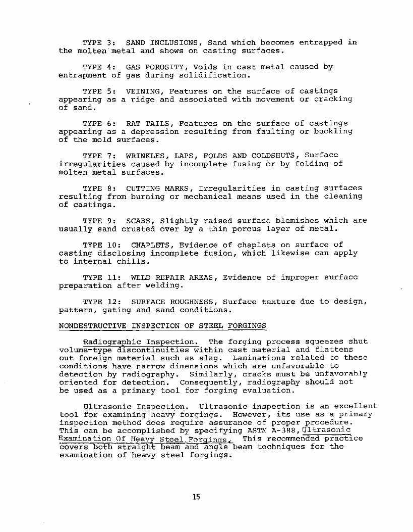
TYPE3: SANDINCLUSIONS,Sandwhichbecomesentrappedinthemolten”metalandshowsoncastingsurfaces.
TYPE4: GASPOROSITY,Voidsincastmetalcausedbyentrapmentofgasduringsolidification.
TYPE5: VEINING,Featuresonthesurfaceofcastingsappearingasa ridgeandassociatedwithmovementorcrackingofsand.
TYPE6: RATTAILS,Featuresonthesurfaceofcastinqsappearingasa depressionresultingofthemoldsurfaces.
TYPE7: WRINKLES,LAPS,FOLDSirregularitiescausedbyincompletemoltenmetalsurfaces.
fromfaultingorbuckling
ANDCOLDSHUTS,Surfacefusingorbyfoldingof
TYPE8: CUTTINGMARKS,Irregularitiesincastingsurfacesresultingfromburningormechanicalmeansusedinthecleaningofcastings.
TYPE9: SCABS,Slightlyraisedsurfaceblemisheswhichareusuallysandcrustedoverbya thinporouslayerofmetal.
TYPE10: CHAPLETS,Evidenceofchapletsonsurfaceofcastingdisclosingincompletefusion,whichlikewisecanapplytointernalchills.
TYPE11: WELDREPAIRAREAS,Evidenceofimpropersurfacepreparationafterwelding.
TYPE12: SURFACEROUGHNESS,Surfacetextureduetodesign,pattern,gatingandsandconditions.
NONDESTRUCTIVEINSPECTIONOFSTEELFORGINGS
RadiographicInspection.Theforgingprocesssqueezesshutvolume-typediscontinuitieswithincastmaterialandflattensoutforeignmaterialsuchasslag.Laminationsrelatedtotheseconditionshavenarrowdimensionswhichareunfavorabletodetectionbyradiography.Similarly,cracksmustbeunfavorablyorientedfordetection.Consequently,radiographyshouldnotbeusedasa primarytoolforforgingevaluation.
UltrasonicInspection.Ultrasonicinspectionisanexcellenttoolforexaminingheavyforgings.However,itsuseasa primaryinspectionmethoddoesrequireassuranceofproperprocedure.Thiscanbeaccomplishedby specifyingASTMA–388,~JltrasonicExaminationOfH.eav~Steel.Forqin~s..Thisrecommendedpracticecoversbothstraightbeamandanglebeamtechniquesfortheexaminationof‘heavysteelforgings.
15
Page 23
Thisistobedonewiththepulse-echoreflectiontypeinstrument.A nominalfrequencyof2 1/4MHzisrecommendedwhereverpractical.However,forcoursegrainedmaterials~~1MHzispermittedanda frequencyaslowas0.4MHzisacceptablefordifficulttopenetratematerialssuchasausteniticsteel.Theactiveareaofthetransducerisre-strictedtoamaximumof1 squareinchforstraightbeamworkandeither1“x 1“or1“x 1/2”forangl-beamscanning.
Approvedcouplantsinclude:water,glycerin,motoroil~orpineoil,butitiscautionedthatcouplingcharacteristicscanbeexpectedtodiffermdconsistencymustbemaintainedbetweenthecalibrationprocedureandtheactualwork...~hisisemphasizedina graphinthatappendixinwhichthesignalamplitudefromreferencereflectorsisplottedagainstsurfacecurvature.Thecurveforoilandglycerindiffersignificantly.
Requirementsaresetforthforinstrumentlinearityregardingsignalamplitude.Thisistobedoneusingapprovedreferenceblockscontainingflat-bottomedholes.Thesameblocksaretobeusedtoestablishtheinstrumentsensitivityforscanningtheworkmaterial.
Thesurfacetobeinspectedmust‘befreeofextraneousmaterialsuchaslooseScqleordirtandthesurfaceroughnessisnottoexceed’25Qu i“nchunlesssostatedinthecont~act=Iftheforgingistobeheattreated,thenexaminationistobedoneafterthatiscompleted.
Inperformingtheultrasonicexamination,a 15%overlapOfpassesis.requiredata scanningratenottoexceed6 in./sec;andrifpossible,attwoperpendiculardirections.Guidanceispresentedforthescanningtechniquetobeusedonforgingsofspecificgeometry-cylinders,hollows,etc.
Asanalternatetocalibrationusingreferenceblocks,atechniqueispresentedwherebyforstraightbeamexamination,thereflectionfromthebacksurfacecanbesetat75%offull-screenheightandsensitivitycanthenbeincreasedbyusingthe’decibelattenuator.Iftheforgingthicknesschanges,recalibrationisrequired.
Duringexaminationoftheforging,inadditiontomonitoringsignalsfromwithintheforgingvolume,theoperatorisrequiredtoalsomonitorthereflectionfromthebacksurface.Thisisdonebecausea signalreductionmaybeindicativeofflawsandalsocouldalerttheoperatortoconditionsofpoorcouplingornonparallelsurfaces.
Forangle-beamscanning~a 45°angle-beamsearchunitisrecommendedandcalibrationistobedoneona rectangularor600”“v-notch”cut3%ofthenominalthicknessor1/4”whicheverissmaller.Ringsandhollowforgingsaretohavea not~honbothsurfacesanda referencelevelcurveistobeconstructedtocompensateforattenuationandbeamscatter:Sensitivityissetbyadjustingthesignalfromthereferencenotchonthebacksideto75%offull-screenheight.
16
Page 24
Itisstatedinthisrecommendedpracticethatforgingsaretoodiversetoestablisha universalqualitylevel,andthatacceptancecriteriashouldbebasedupona realisticappraisalofservicerequirements.
Guidanceisprovided,however,intwoseparateways:First,~certaintypeindicationsaretoberecorded.Theseinclude(1)signals10%theamplitudeofthebackreflectionsignalorthoseequaltoorinexcessof100%ofthereferenceamplitudeobtainedusingthecalibrationblock,(2)indicationscontinuousona plane,(3)indicationswhichtravelwithmotionofthesearchunit,(4)clustersofindications,(5)reductionin,backreflectionsignalamplitudeexceeding20%oftheoriginalamplitude~(6)foranglebeamexamination- anysignal50%orlargerthanthereferenceline.Second,itissuggestedthatacceptancebeestablishedbasedupononeormoreofthefollowingcriteria:(1)a limiton signalamplitudeexpressedasapercentageofthebackreflection,(2)a limitonsignalamplitudeexpressedinrelationtothdsignalamplitudeobtainedincalibrationusinga referenceblock,(3)a limitonthereductioninsignalamplitudeofthebacksurfacereflection-expressedasa percentage,(.4)a combinationofsignalamplitudeandreductioninbacksurfacesignalamplitude,and(5)foranglebeamexamination- alimitonsignalamplitudeexpressedasapercentageofthereferenceline.
MaqneticParticleInspection.Steel-forgingsmayalsobeinspectedfordisconitnuitiesopentothesurfaceusingeitherthewetordrymethodofmaqneticparticletestinq.Procedurecanbecontrolledbyspecif~ingAS~MA-275,MaqneticParticleExaminationOfSteelForqinqs.Thisstandardmethodconsidersbothwetanddrymagneticparticletestinqofsteelforgings.Itprovidesproceduralguidanceconstitutinggoodpractice-forthecontinuous,surge,andresidualmethodsofmagnetizationandthetwogeneraltypesofmagnetization,longitudinalandcircular.Itrequiresthattwoapproximatelymutuallyperpendicularexaminationsbeconductedseparatelyoneacharea.
Thisstandarddoesnotpresentanyacceptancestandardsanddoesnotdefineanyqualitylevels.However,itstatesthatstandardsforacceptanceshallbespecifiedinthecontractororder.
Althoughacceptancecriteriaisnotsetforth,thisstandarddoesdefineanddescribe”thetypesdfindicationswhichmaybeobtained.Thesearegroupedintothreebroadcategories:(.1)surfacedefectssuchasforginglapsandfolds,laminardefects,flakes,andcracksduetoheattreating,shrinkage,grinding,andetchingorplating;(2)subsurfacecrackssuchasstringersofnonmetallicinclusions,largenonmetallic,cracksintheunderbeadofweldsandforgingbursts;and(3)nonrelevantindicationssuchasmagneticwriting,changesinsection,weldedgesandflowlines.
17
Page 25
Nonrelevantindicationsmustberesolvedbyothermethodsofnondestructivetestinganddemonstratednonrelevantoreliminatedbysurfaceconditioning.Sincesubsurfaceindicationscannotbefoundusingalternatingcurrent,andifthistypeofdiscontinuityisofimportance,theuseofmethodsemployingdirectcurrentmustbespecified.Criteriaforevaluatingdiscontinuitiesshouldbebasedonsize,number,locationandforlinearindicationsthelengthanddirection.
UseofthisstandardistobesupplementedbythepreviouslymentionedE-183-63andE-109-63whichconsiderthewetanddrymethodsofmagneticparticleinspection.
LiquidPenetrantInspection,Whilemagneticparticleinspectionisa super~orandfasterwaytoinspectsteelforgings~liquidpenetranttestingcanbedoneandinvolvesthesamestandardsandprocedurespreviouslysetforthforcastings.
VisualInspection.Ifsurfacetextureisimportant,theAmericanNationalStandardASNIB46.1SurfaceTexturecanbeusedforthispurpose.
NONDESTRUCTIVEINSPECTIONOFTHICKWELDS
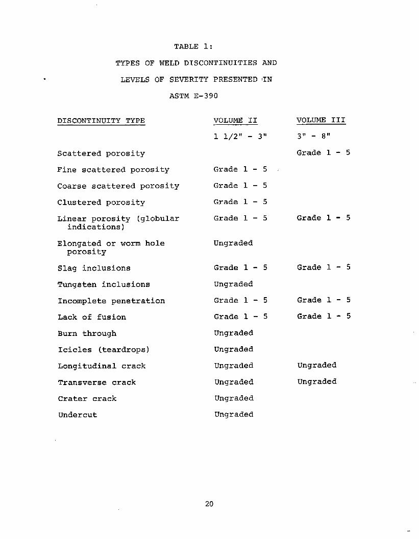
Radiography.ThequalityofradiographyforsteelweldsiscontrolledusinqthesamespecificationsE-94andE-142,previouslydiscuss=dunder’the”radiographicinspectionofsteelcastings.DiscontinuitiesrevealedbyradiographycanbeevaluatedusingASTME-390,.Ref@renceRadiograph=‘or‘teelFusionWelds.Volume11isapplicabletoweldsbetween1 1/2”and3“. VolumeIIIisforwelds3“- 8“thickness.Table1liststhetypesandnumberofgradesofseverityineachvolume.
Aswiththecastingreferenceradiographs,thesearenotstandardsinthemselves;however,theycanbeusedtocreateacceptancecriteriabycontractuallyspecifyinga maximumacceptablegradeofseverityforeadlitypediscontinuity.Forexample,referencingASTME-390,themaximumpermissibleseveritylevelforeachtypediscontinuityina weldof2 1/2”isasfollows:
FineScatteredPorosity Grade4CoarseScatteredPorosity Grade3Clusteredporosity Grade‘4LinearPorosity Grade1ElongatedPorosity NoneSlagInclusions Grade2TungstenInclusions N@IncompletePenetration Grade1LackofFusion Grade1BurnThrough NoneIcicles
18None
Page 26
Cracks NoneUndercut None
UltrasonicInspection.Theultrasonicmethodcanbeusedonthickweldswithadvantage.Theordinaryanglebeammethod,.slightlymodified,isapplicableandinadditionthatinspectioncanbecomplementedusingthestraightbeam.Theprocedure,however,ismorecomplexwiththickweldsandshouldbecontrolledinaccordancewithASTME-164,uLTRASONICCONTACTEXAMINATIONOFWELDMENTS.Thisstandard-recommendedpracticeisapplicabletoweldsUp to eiqhtindhesthicknessusinqeitherstraightbeamoranglebeamtechniques.Personnelperformingtheultrasonicexaminationshouldbeproperlytrained.SNT-TC-lAisreferredtoforqualification.
Noacceptancecriteriaispresentedanditislefttocontractualagreementtoestablishcalibrationstandards.
Theultrasonicinstrumentusedforweldexaminationshouldhavean“A-scan”presentationanda capabilityforgeneratingtherecommendedinspectionfrequenciesof1.0– 5.0MHZ.Quantitativeevaluationofflawsrequirestheinstrumenttohaveeithera linearamplifier,calibratedgaincontrolora distancecompensatingamplifier.Therearerequirementsforhorizontallinearity.
Searchunitsassmallas1/4inchdiameterarerecognizedassuitableforsomeapplicationsandsizesaslargeas1 1/8inchdiameterarepermitted.Forshearwaveinspection,rectangularprobeshavinga lengthtowidthratiogreaterthantwoarenotrecommended.
Shearwaveanglesarenotspecified,buta tableissetforthwherebyoptimumanglesarecorrelatedwithvariousbasemetalthicknesses.Thenominalangleindicationonthetrans-ducerwedgeshouldbecheckedtoavoiderroneousconclusionsregardingdiscontinuitylocation,Twomethodsforaccomplishingthis,thepolarcoordinateandrectangularcoordinate,arepresentedinanannex“toASTMI?-164.
Calibrationisconsideredindetail.A procedureispresentedfordeterminingtheactualdistancetraveled.Thisisnecessaryinordertoaccuratelylocatediscontinuities.Anequalanglereflectingsurface,incorporatedintocertaintestblocks,isrecommended,butthismayalsobedoneutilizingthereflectionfroma notch.Testblockswithside-drilledhales(illustratedinanannex)areusefulforperformingdistance,amplitude,positionanddepthcalibration.Inaddition,thistypeoftestblockcanbeusedtodeterminetherelationbetweendepthordistancetraveledandsignalamplitudefluctuations.Thisistobedoneeitherbyconstructinga curveontheoscilloscopescreenorwithinstrumentsso equipped,usingthedistance- amplitudecontrolstoobtainsignalsofequalscreenheightfromalldepthswithinthetestrange.
19
Page 27
TABLE1:
TYPESOFWELDDISCONTINUITIESAND
LEVELSOFSEVERITYPRESENTEDIN
ASTME-390
DISCONTINUITYTYPE
Scatteredporosity
Finescatteredporosity
Coarsescatteredporosity
Clusteredporosity
Linearporosity(globularindications)
Elongatedorwormholeporosity
Slaginclusions
Tungsteninclusions
Incompletepenetration
Lackoffusion
Burnthrough
Icicles (teardrops)
Longitudinalcrack
Transversecrack
Cratercrack
Undercut
VOLUMEII1 l/2~1- 311
Grade1 - 5 .
Grade1 - 5
Grade1 - 5
Grade1 - 5
Ungraded
Grade1 - 5
Ungraded
Grade1 - 5
Grade1 - 5
Ungraded
Ungraded
Ungraded
Ungraded
Ungraded
Ungraded
VOLUMEIII311_ ~11
Grade1 - 5
Grade1 - 5
Grade1 - 5
Grade1 - 5
Grade1 - 5
Un~raded
Ungraded
20
Page 28
It is recognizedthattheremaybecouplingdifferencesbetweenthetestblocksurfaceandthatoftheworkpiece.A testblock+withsurfaceroughnessequivalenttothatoftheworkwouldcircumventthedifficultybutmaynotbefeasibletoprepare.Alternatively,atransfertechniquemaybeused.Thisprocedureutilizesa notchinthebasiccalibrationblockanda similarnotchmachinedintotheweldseam.Theratioof”signalamplitudefromthesetwonotchespermitsadjustmentofinstrumentsensitivitytoachievea validcalibrationforuseontheworkpiece.Allofthecalibrationproceduresandtestblocksaredescribedindetailinthetestandannex.
Whenlongitudinalwaves(straightbeam)areusedinweldinspection,thecalibrationprocedureisessentiallyidenticaltothatforshdarwaves.Itispointedout,however,thatifbothmethodsareusedanditisdesiredtohaveequivalentwavelengthswithinthetestmaterial,thelongitudinalprobeshouldbea frequencyaboutdoublethatoftheangleprobe.
Thisrecommendedpracticeislimitedtospecificweldgeometries:Buttweld,~~TeelljointsandcornerjOints,Bothflatandcurvedsurfacesareconsideredandspecificinspectionproceduresaresetforthforeach.
Severaltechniquesaresuggestedfordiscontinuityevaluation:signalamplitudecanbeusedtomeasuredefectseverity,’butitisemphasizedthatthisshouldbebasedonexperiencewithactualdefectsandnotartificialreflectors;discontinuitydimensionscanbedeterminedlocatingthepointswheresignalamplitudefallstoonehalf;orientationcanbededucedfromrelativesignalamplitudesobtainedbyalteringthedirectionofinspection;andreflectorshapemaybededucedfromtherelativesharpnessofthesignal.
Thedeterminationofdiscontinuitydimensions,orientationandshapemaybeusefulbutshouldnotbea basisforacceptancecriteriabecauseofthegreatdependenceon operatorskill.
MaqneticparticleInspection.Themagnetic:.particlemethodmaybeusedtoinspectweldsfordiscontifiuitiesopentothesurfacebefouemoresophisticatedtechniquesareused,Itcanalsobevaluableforvertfyingcompletedefectremovalpriortorewelding.
Withtheexceptionoftheelectricalcurrentrequirements,thetechniqueforinspectingweldswithmagneticparticlesisindependentofthethickness.GoodpracticeissetfortihinthepreviouslydiscusseddocumentE-109.
TechnicaldetailsinvolvingthemagneticparticleinspectionofweldsarepresentedinWeldingInspectionoftheAmericanWeldingSocietyandinSSC-253,A Guide”fortheNondestructiveTesting“o’fNon-ButtWeldsinCommercialShi~s- PartiOne.
21
Page 29
I 20
80
60
4
VisualInspection.Asidefrompossiblecrackdetection,theprimaryapplicationofvisualinspectionisthedeterminationofsatisfactoryweldcontourrequirements.GaugesmaybeusefulandtheiruseisdescribedinsSC-253,previouslylisted.
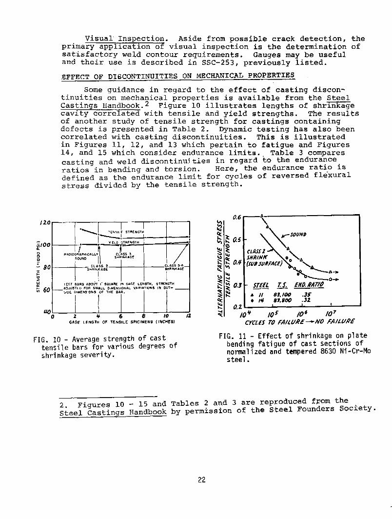
EFFECTOFDISCONTINUITIESONMECHANICALPROPERTIESSomeguidanceinregardtotheeffectofcastinudiscon-
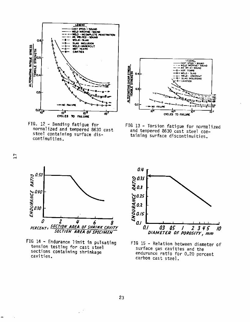
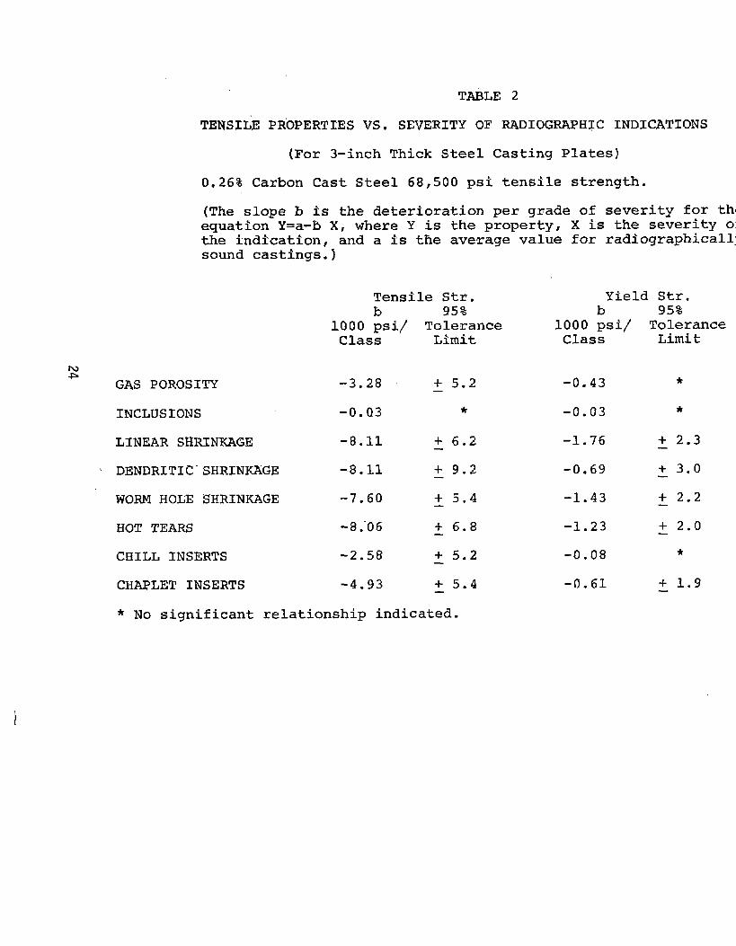
tinuitiesonmechanicalpropertiesisavailablefrom-theSteelCastingsHandbook.2Figure10illustrateslengthsofshr=ecavitycorrelatedwithtensileandyieldstrengths.TheresultsofanotherstudyoftensilestrengthforcastingscontainingdefectsispresentedinTable2. Dynamictestinghasalsobeencorrelatedwithcastingdiscontinuities.ThisisillustratedinFigures11,12,and13whichpertaintofatigueandFigures14,and15whichconsiderendurancelimits.-Table3 comparescastingandwelddiscontinuitiesinregardtotheenduranceratiosinbendingandtorsion.Here,theenduranceratioisdefinedastheendurancelimitforcyclesofreversedfle-xuralstressdividedbythetensilestrength.
I I I I I
-t,●�
✚✝
YIELDsTRENGTH
r
F!AD1OGRAPHICOLLY CLA$$3SOUND SHRINN4GF
-t-
CLA5$ 2 GLASS$.&_sMRlhKAGL SI.IRINHAGE
TESTBARSABOtiT”1-SQUAREINGnGELENGTH.STRENGTHAoJu5tED FOR SMALL DIMENS1ONALvnRIA?lONSIN OUT- _
‘510E O1MENS1ONSOF THE BAR, I IL_u_LLLo 2 + 6 8 10 1:GAGELENGTHOF TENSILE SPICIMENS( INCHESI
FIG.10-Averagestrengthofcasttensilebarsforvariousdegreesshrinkageseverity.
2. Figures10- 15andSteelCastingsHandbook
of
CYCLE5TO[A/lURE4N0FAILURE
FIG.11-Effectofshrinkageonplatebendingfatigueofcastsectionsofnormalizedandtempered8630Ni-Cr-Mosteel.
Tables2 and3 arereproducedfp~mthebypermissionoftheSteelFoundersSQciet~.
22
—
Page 30
‘cl\
CLzl 1s
1#
1
~ES 70 FM&isId
FIG.12-Bendingfatiguefornormalizedandtempered8630caststeelcontainingsurfacedis-continuities.
0~68
PERCEAIT:SECTIONAREAOfSHRINKCAVITYSECTIONAREAOFSPECIMEN
FIG14-EnduranceWnitinpulsatingtensiontestingforcaststeelsectionscontainingshrinkagecavities.
LEC.EUD—C4ST STESL-WD‘ -- WELDtMCMINE-mMB-.—AS WELD. $@JND‘O- HOTTURS
0.4
t
‘O-WI-D-SUG—x- WLO- uum@T
\—b SLAGlUCLUSlo#$U: 0- CAV~lES
1 Iw I 1W
I
~L~OTO FAJm107
FIG13-Torsionfatiguefornormalizedandtempered8630caststeelcon-tainingsurfacediscontinuities.
al 03 05 I 23Y5 10DIAMETEROFPOROSITY,mm
FIG15-Relationbetweendiameterofsurfacegascavitiesandtheenduranceratiofor0.20percentcarboncaststeel.
23
Page 31
TABLE2
TENSIL.EPROPERTIESVS.SEVERITYOFRADIOGRAPHICINDICATION
(For3-inchThickSteelCastingPlates)
0.26%CarbonCastSteel68,500psitensilestrength.
(.Theslopeb is thedeteriorationpergradeofseverityforthequationY=a-bX,whereY istheproperty,X istheseverityotheindication,anda istheaveragevalueforradiographisoundcastings.)
TensileStr.b 95%
lQOOpSi\ToleranceClass Limit
h)- GASPOROSITY -3.28 + 5.2—
INCLUSIONS -0.03 *
LINEARSIiRINKIWE -8.~1 ~ 6.2
‘ DENDRITIC’SHRINKAGE-8.11 + 9.2—WORMHOLESHRINKAGE -7.60 + 5,4—HOTTEARS -8:06 + 6.8—CHILLlNSERTS -2.58 + 5.2—CHAPLETINSERTS -4.93 : 5.4
YieldStr,b 95%
1000psi\ToleranClass Limit
-0.43
-0.03
-1.76
-0.69
-1.43
-1.23
-0.08
-0.61
*
*
+ 2.3—+ 3.0
+ 2.2
+ 2.0—*
+ 1.9—* Nosignificantrelationshipindicated.
Page 32
TypeofSpecimen
(2T
CastSteel-Sound*Weld-Machine-SoundslagInclusionsAsWelded-SoundWeld-SlagWeld-Undercut
~ CaVitiesHotTears
NT
CastSteel-Sound*Weld-Machine-SoundAsWelded-SoundWeld-SlagWeld-UndercutCavitiesSlagInclusionsHotTears
TABLE3
COMPARISONOFENDURANCERATIOS
EnduranceRatioinBending_
0.3100.2510.2460.2410.2340.2330.1170.274
0.3610.3520.3450.3140.2800.2350.2920.245
** (t/h) =EnduranceRatioinTorsionEnduranceRatioinBending
IN BENDINGANDTORSION
EnduranceRatioinTorsion (t..
0.2980.2300.2300.2210.1840.1950.1000.146
0.2700.2610.2500.2340.2300.1950.2080.241
0.90.91.00.90.70.80.80.5
0.0.0.0.0.0.0.0.
EnduranceRatt ‘t’m)= Maxwell-Vo
* End.qranceRatiousingR.R.MooreSpecimen(QTunnotched.390,QTnNTunnotched.395,NTnotched.252).
18
Page 33
SUMMARYANDCONCLUSIONS
Codebodies,notablyASTM,haveproducedproceduralguides,standardmethodsandrecommendedpracticeswhichcanbeusedtoassureproperinspectionprocedureforthevariousmethodsofnondestructivetesting.Theseareapplicabletoheavysteelcastings,forgings,andweldments.Inaddition,ASTMoffersreferenceradiographsandreferencephotographs~whichmaYbeusedincontractualagreements.Inthespecificcaseofsteelcastings,ASTMdefinesseverallevelsofqualityforultrasonicinspection.However,thesedocumentsdonotsetforthacceptancecriteriaorofferrecommendationsinthatregard.
Discontinuitiesfoundby nondestructivetestingmust beevaluatedand theASTMdocumentsdiscussedinthisreportdoprovideguidanceinthisregard.Thisisdonebydescribingtheparameterswhicharegenerallyagreedtobeofsignificanceandwhichshouldbea partofthecontractualagreement.Itislefttotheusertoquantifytheseparameters.accordingtoservicerequirementsorotherconsiderations.
26 q-U.S. GOVERNMENTPRmTINGOFFICE:1981- 727.063/1514
—
Page 34
I
SHIP RESEARCH COMMITTEEMari t’ime Transportation Research Board
National Acade~ of Sciences - National Research Council
agency
********
The Ship Research Conmittee has technical cognizance of the inter-Ship Structure Committee’s research program:
Mr. A. f).Haff, Chairnmn, ConsuZtunt, Annapolis, MDProf. A. H.-S. Ang, C@i Z..%grg. Dept.,Universityof IIZ.tn&s,Champa{gn, ILMr. A. C. McC1 ure, Abn C. McClureAssociates,Inc.,Houston,TXDr. k!. R. Porter, Vice Presidentfor AcademicAffairs,State Univ. of I’?a YcPk
Maritime (701ZegeMr. D. A. Sarno, Manager-Mechanics,ARMCO i“nc.,Middletown,OHProf. H. E. Sheets, ET. of E~’ineemkg, A“kzlysie& Technology, Im.,
Stonington, CTMr. J. E. Steele, NavalArch{tect,Qvakertmm, PAMr. R. W, Rumke, IkcecwtiveSecretary,Ship ReeearchComnittee
********
The Materials, Fabrication, & Inspection Advisory Group prepared theproject prospectus, evaluated the proposals for this project, provided the1iaison technical guidance, and reviewed the project reports with theinvestigator:
Mr. D. A. Sarno, Chairman, Manager-Mc?chanioe,ARMCO Inc.,M&3db?+m, OHMr. W. C. Brayton, Consultant, ~ooa Raton, FLMr. W. Dukes, Chief’Engineerfor Structures,Be2Z Aerospace Teztron, New Orteans, LADr. W. C. Leslie, Dept.of Matmials d Met. 17ngrg.,Univ.c.f?iickigan,MIMr. P. W. Marshal I, C%i 1.EngineeringAdvisor,SHELLOiZ Cc,.,l?ouzixxz,TXDr. E. J. Ripling, President, Mater+iaZsResearchlib., Inc., GZ.emood,IL
Page 35
SHIP STRUCTURE COMMITTEE PUBLICATIONS
Xhesedocwnentaare distributedby the ??ationalTeehnica2InformationService,Springfield,VA 22314. Thesech -umentshave been announcedin the ClearinghouseJournalU. S. GovernmentResearch.4DevelopmentReports (USGRvR)under the indicatedAD nwnbem.
SSC-287, Examinationof service ad stress Data of fipee Shipsfor DevelopnentO> fill GirderLoad Criteriaby J. F. Dalzell , N. M. Maniar: and!4.W. Hsu. 1979. AD-A072910.
SSC-288, The Effectsof Varying5hip Hull Frwportionsand RuZ.1 Ma&?rio7.son [!uZ2Flexibi2ityBendingand VibratorgStressesby P. Y, Chang. 1979.AD-A075477 .
5SC-289, A Methodfop Economic Trade-Offsof AZ.termteShip Struttura1 MatetiaZsby C. R. Jordan, J. B. Montgomery, R. P. Kt-umpen,and D. J. Woodley.1979. AD-A075457 .
SSC-290, Sign< ficanoe and Control of .hnellarTea?ingof StealHate {.xth<,Shipbuikiing Industryby J. Sommel la. 1979. AO-A075473.
SSC-291, A Designl+ocedurefor Minimizing.?ropeller-~ndueedVibrationix zul1Struotura2E7,ementsby O. H. Burns ide, D. O. Kana, and F. E. Reed..1979. AD-A079443.
SSC-292, Reporton Ship V<b?ationSymposium178- SheratozNationaZ Hotel,ArZington, VA. by E. Scott Oilion. 1979. AD-P079291.
SSC-293,Underm!der A’ondestrwtive Testing of Ship Hull Welds by R. ‘Youshaiwand C. Dyer. 1979. AD-A079445 .
SSC-294, Fur%+erSumveyof InservicePerformance of Structv~al Detiaih byC. R. Jordan and L. T. Knight. 1979. AD-A086019.
SSC-295, NondestructiveInspectionof Lo itudina2Sti.ffenerButt w lds in% 1980. AD-A085352.Comewid VesseZs by R. A. Yous aw.
SSC-296, Reviewof FiZZet WeZd StrengthParametersfor S%ipbwiZdingbyC-L Tsai, K. Itoga, A. P. Malliris, W. C. McCabe, and K. Masubuchi,1980. AO-A085356.
SSC-297, @>aluakion of LiquidDynamicLoads in SlackLNG CargoTads byP. A. Cox, E. 8. 8owles, and R. L. 8ass. 1980.
SSC-298, Investigationof .%ee2S for Improved,%2&bi”2.ity~n Ship Cons.tz,uctie>:-PhaseI by R. W. Vanderbeck. 1980.
SSC-299, U2t<mateStrengthofa Ship’sHull Girderin plasticand Buckling WAiksby A. E. Mansour and A. Thayambal li. 1980.