34
. SUNNICA ENERGY FARM Preliminary Environmental Information Report Chapter 3: Scheme Description Sunnica Ltd AUGUST 2020 www.sunnica.co.uk

.
SUNNICA ENERGY FARM
Preliminary Environmental Information Report Chapter 3: Scheme Description
Sunnica Ltd
AUGUST 2020
www.sunnica.co.uk

Sunnica Energy Farm Preliminary Environmental Information Report Volume 1: Main Report (Chapter 3: Scheme Description)
AECOM
Contents
3. Scheme Description ................................................................................ 1 Introduction ................................................................................................................................ 1 Rochdale Envelope .................................................................................................................... 2 Design Parameters .................................................................................................................... 2 Components of the Scheme ...................................................................................................... 7 Electricity Export Connection to National Grid ......................................................................... 19 Construction ............................................................................................................................. 21 Operational Activities ................................................................................................................ 29 Decommissioning ..................................................................................................................... 29 References ............................................................................................................................... 31
Plates
Plate 3-1. Illustration of a typical 144 cell solar panel ............................................................................. 9 Plate 3-2. Solar panels with south facing configuration .......................................................................... 9 Plate 3-3. Outdoor solar station ............................................................................................................ 10 Plate 3-4. Example of white indoor solar station exterior (image reproduced courtesy of Power Electronics)............................................................................................................................................ 11 Plate 3-5. Indoor solar station interior (image reproduced courtesy of Power Electronics) .................. 11 Plate 3-6. Typical outdoor centralised inverter ...................................................................................... 12 Plate 3-7. Typical outdoor transformer .................................................................................................. 12 Plate 3-8. Typical transformer cabin (including switchgears) (indoor solar station) (Image reproduced courtesy of Selma) ................................................................................................................................ 13 Plate 3-9. Cabin indoor switchgear used in the outdoor solar station solution. .................................... 13 Plate 3-10. Typical battery storage compound configuration (image reproduced courtesy of Fluence Energy). ................................................................................................................................................. 15 Plate 3-11. Typical deer security fence ................................................................................................. 17 Plate 3-12. Typical transformer compound fencing............................................................................... 17 Plate 3-13. Cross section of access track. ............................................................................................ 18 Plate 3-14. Example of an access path. ............................................................................................... 19 Plate 3-15. Piling of module mounting structures. ................................................................................ 22 Plate 3-16. Construction staff mounting solar PV modules by hand..................................................... 22 Plate 3-17. Forecast total Staff vehicles per day during the construction period .................................. 24 Tables
Table 3-1. Indicative details of the design parameters used for the PEI Report assessment ................ 3 Table 3-2 Construction phase traffic estimates for all Sites. ................................................................ 24 Table 3-3 Construction plant and machinery numbers and type.......................................................... 25 Table 3-4 Estimated waste arisings during construction. ..................................................................... 27 Table 3-5 Estimated waste arisings during decommissioning. ............................................................ 30

Sunnica Energy Farm Preliminary Environmental Information Report Volume 1: Main Report (Chapter 3: Scheme Description)
AECOM 3-1
3. Scheme Description Introduction
This chapter provides a description of the Scheme. The physical characteristics of the Scheme are described alongside the proposed programme for site preparation, construction and decommissioning works. The key activities that would be undertaken during construction, operation (which includes maintenance), and decommissioning are included in this chapter to inform each of the technical assessments included in Chapters 6 to 13.
This chapter is supported by the following figures in Volume 3:
• Figure 3-1: Sunnica East Sites A and B Parameter Plan • Figure 3-2: Sunnica West Sites A and A Parameter Plan • Figure 3-3: Solar Panel Design (illustrative) • Figure 3-4: Inverters (illustrative) • Figure 3-5: Transformers (illustrative) • Figure 3-6: Switchgears (illustrative) • Figure 3-7: Cable Cross Sections (illustrative) • Figure 3-8: Cross-section for water body crossing (illustrative) • Figure 3-9a: Sunnica West A Substation Elevation • Figure 3-9b: Sunnica West A Substation General Arrangement • Figure 3-10a: Sunnica East Site A Substation Elevation • Figure 3-10b: Sunnica East Site A Substation General Arrangement • Figure 3-11a: Sunnica East Site B Substation Elevation • Figure 3-11b: Sunnica East Site B Substation General Arrangement • Figure 3-12: Sunnica East Sites A and B Access • Figure 3-13: Sunnica West Sites A and B Access • Figure 3-14: Sunnica East Sites A and B Drainage Strategy • Figure 3-15: Sunnica West Sites A and B Drainage Strategy • Figure 3-16a: Grid Connection Route A between Sunnica East Site A
and Sunnica East Site B • Figure 3-16b: Grid Connection Route A between Sunnica East Site B
and Sunnica West Site A • Figure 3-16c: Grid Connection Route B between Sunnica West Site A
and Sunnica West Site B • Figure 3-16d: Grid Connection Route B between Sunnica West Site B
and Burwell • Figure 3-17a: Burwell Substation Elevation

Sunnica Energy Farm Preliminary Environmental Information Report Volume 1: Main Report (Chapter 3: Scheme Description)
AECOM 3-2
• Figure 3-17b: Burwell Substation General Arrangement • Figure 3-18a Sunnica East Sites A and B Construction Compounds and
Access • Figure 3-18b: Sunnica West Sites A and B Construction Compounds
and Access • Figure 3-19: Preferred and Alternative Locations For Burwell National
Grid Substation Extension
Rochdale Envelope
The Scheme comprises an energy farm with Solar PV and Battery Energy Storage System (BESS) infrastructure. Solar PV and BESS are rapidly evolving. As a result, the parameters of the DCO will maintain some degree of flexibility to allow the latest technology to be utilised at the time of construction. This is explained in this chapter.
In order to ensure a robust assessment of the likely significant environmental effects of the Scheme, the EIA has been undertaken adopting the principles of the ‘Rochdale Envelope’ where appropriate, as described in the Planning Inspectorate Advice Note 9 (Ref. 3-1). This involves assessing the maximum (and where relevant, minimum) parameters for the Scheme where flexibility needs to be retained. Where this approach is applied to the specific aspects of the EIA, this has been confirmed within the relevant chapters of this PEI Report. It sets worst case parameters for the purpose of the assessment but doesn’t constrain the Scheme from being built in a manner that would lead to lower environmental impacts.
Indicative timescales for the construction and operation of the Scheme that have been assumed for the purposes of the assessments are as follows:
• It is currently anticipated that (subject to the necessary consents being granted) construction work will commence in Autumn/Winter 2022 and will run for 24 months;
• It is currently anticipated that the Scheme will commence commercial operation from Spring 2025. Depending on the final construction programme, operation may overlap with the construction phase; and
• The operational life of the Scheme is anticipated to be 40 years and decommissioning would be in 2065.
Construction of the Scheme is detailed in Section 3.6 of this chapter.
It is envisaged that the Scheme will have a design and operational life of at least 40 years; therefore, decommissioning activities are currently anticipated to commence on or after 2065.
Design Parameters
The design of the Scheme is an iterative process, based on preliminary environmental assessments and consultation with statutory and non-statutory consultees. Chapter 4: Alternatives and Design Evolution
Sunnica Energy Farm Preliminary Environmental Information Report Volume 1: Main Report (Chapter 3: Scheme Description)
AECOM 3-3
describes this process further, including options that have been considered and discounted or amendments made to the Scheme design to date.
A number of the design aspects and features of the Scheme cannot be confirmed until the tendering process for the design and construction of the Scheme has been completed. For example, the enclosure or building sizes may vary, depending on the contractor selected and their specific configuration and selection of plant.
Use of the Rochdale Envelope approach is therefore being adopted to present a likely worst-case assessment of potential environmental effects of the different parameters of the Scheme that cannot yet be fixed. Wherever an element of flexibility is maintained, alternatives have been assessed and the likely worst-case impacts have been reported in the PEI Report. Work will continue to further refine the proposed options within the DCO Site prior to submission of the DCO application, where possible.
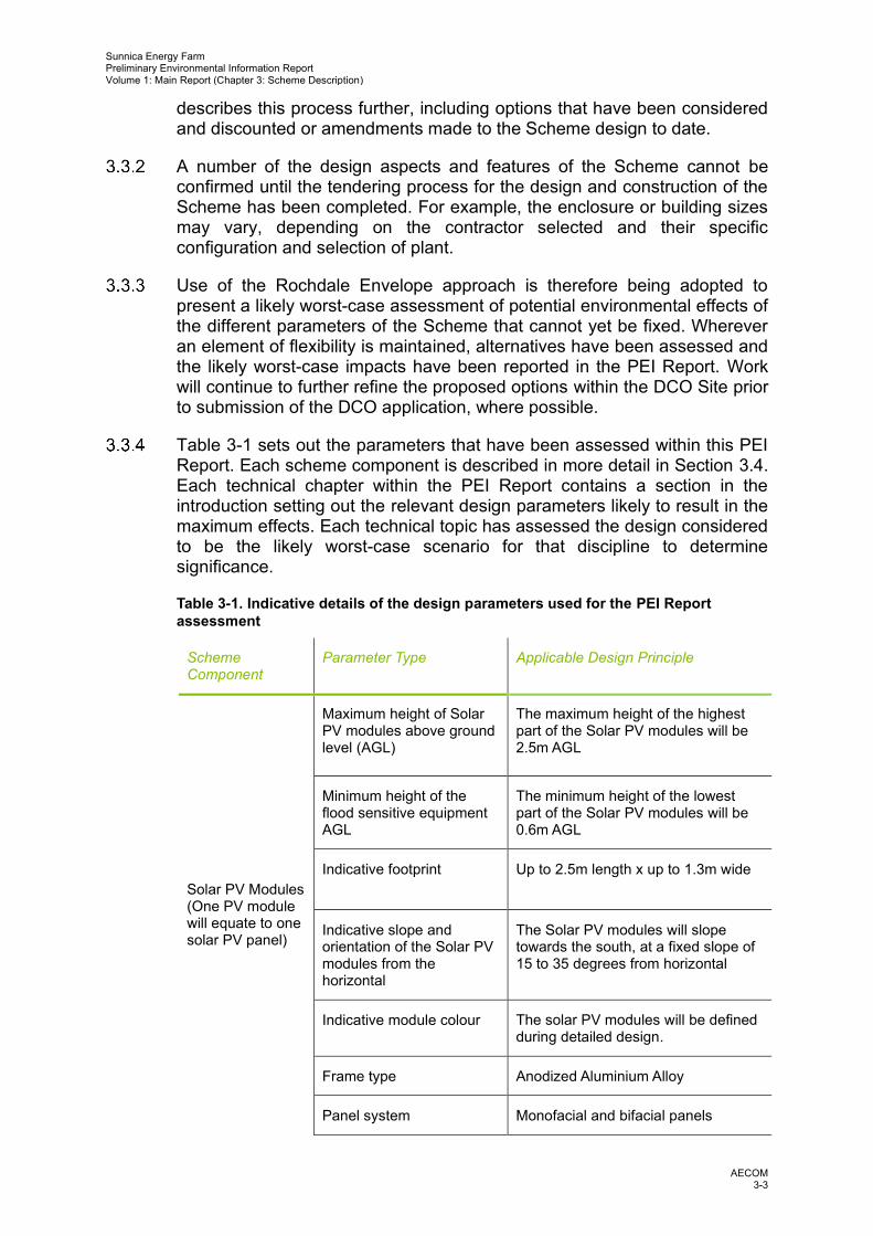
Table 3-1 sets out the parameters that have been assessed within this PEI Report. Each scheme component is described in more detail in Section 3.4. Each technical chapter within the PEI Report contains a section in the introduction setting out the relevant design parameters likely to result in the maximum effects. Each technical topic has assessed the design considered to be the likely worst-case scenario for that discipline to determine significance.
Table 3-1. Indicative details of the design parameters used for the PEI Report assessment
Scheme Component
Parameter Type Applicable Design Principle
Solar PV Modules (One PV module will equate to one solar PV panel)
Maximum height of Solar PV modules above ground level (AGL)
The maximum height of the highest part of the Solar PV modules will be 2.5m AGL
Minimum height of the flood sensitive equipment AGL
The minimum height of the lowest part of the Solar PV modules will be 0.6m AGL
Indicative footprint Up to 2.5m length x up to 1.3m wide
Indicative slope and orientation of the Solar PV modules from the horizontal
The Solar PV modules will slope towards the south, at a fixed slope of 15 to 35 degrees from horizontal
Indicative module colour The solar PV modules will be defined during detailed design.
Frame type Anodized Aluminium Alloy
Panel system Monofacial and bifacial panels

Sunnica Energy Farm Preliminary Environmental Information Report Volume 1: Main Report (Chapter 3: Scheme Description)
AECOM 3-4
Scheme Component
Parameter Type Applicable Design Principle
(monofacial/bifacial)
Solar PV Array works area (linked assembly of solar PV modules)
Location See Figures 3-1 and 3-2.
The maximum developable area is:
• Sunnica East Site A – 179.0 ha
• Sunnica East Site B – 238.7 ha
• Sunnica West Site A – 345.5 ha
• Sunnica West Site B – 36.2 ha
Solar PV Module Mounting Structures
Rack Each string of modules will be mounted on a rack made with galvanized steel or Magnelis®
Indicative foundations Most likely to be galvanized steel poles driven into the ground. Maximum depth of 3.5m.
Indicative separation distance between rows
2m at the closest point and 12m at the furthest point. This will depend on the local ground topography.
Solar Station (a station comprising an inverter, a transformer and the switchgears)
Type The solar station will either comprise independent equipment outdoors, or all equipment will be held within an International Organisation for Standardisation (ISO) High-Cube Container
Indicative number of solar stations
136. The indicative number of solar stations range from 2 to 13 per Works Area1 and are illustrated on Figures 3-1 and 3-2.
Indicative dimensions The maximum parameter of the solar station will be up to 17m by 6.5m footprint, and 3.5m in height. This will either be entirely enclosed by a container (indoor) or the equipment would be sited outside of a container (outdoor). This will depend on the supplier.
Colour Externally finished in keeping with the prevailing surrounding environment.
Indicative foundations Compacted gravel and reinforced concrete with a thickness of 0.2m. Maximum depth of 1m.
1 Works Area – indicative breakdown of the Sites into individual land parcels to allow easy reference to the proposed infrastructure of each area as shown on Figure 3-1 and 3-2.

Sunnica Energy Farm Preliminary Environmental Information Report Volume 1: Main Report (Chapter 3: Scheme Description)
AECOM 3-5
Scheme Component
Parameter Type Applicable Design Principle
Inverters (convert the direct current electricity collected by the PV modules into alternating current):
Type of inverter Centralised inverters
Indicative dimensions of inverters
For outdoor stations, the maximum parameters will be 6.5m by 9m in plan and 3.5m in height.
For indoor station, the units will be housed within the solar station footprint.
Transformers (control the voltage of the electricity generated before it reaches the substations):
Type of transformer Depending on whether or not the components are housed within a container, the transformer will either be outdoor or within the solar station.
Indicative dimensions of transformers
Housed within the solar station container, or if standalone housed outside they will have a max footprint of 6.5m by 5.5m and a max height of 3.5m
Colour of transformers Externally finished in keeping with the prevailing surrounding environment.
Switchgear (cells) (a combination of electrical disconnect switches, fuses or circuit breakers used to control, protect and isolate electrical equipment):
Type of switchgear Depending on whether or not the components are housed within a container, the switchgear will either be outdoor or within the solar station.
Indicative dimensions of switchgear
Housed within the solar station container, or if standalone housed outside they will have a max footprint of 6.5m by 2.5m and a max height of 3.5m
Colour of switchgear Externally finished in keeping with the prevailing surrounding environment.
Onsite cabling (between PV modules and inverters)
Type Low voltage onsite electrical cabling is required to connect the PV modules and Battery Energy Storage System to inverters (typically 1.5/1.8 kV cables) and the inverters to the transformers onsite (typically 0.6/1 kV

Sunnica Energy Farm Preliminary Environmental Information Report Volume 1: Main Report (Chapter 3: Scheme Description)
AECOM 3-6
Scheme Component
Parameter Type Applicable Design Principle
cables).
Cabling will be above ground level between the PV modules. These will be fixed to the mounting structure along the row of racks. Cabling between the PV modules and inverters will be buried within underground trenches.
Indicative cable trench dimensions
Maximum dimensions: 1.1m deep and 1m wide.
Battery Energy Storage System (BESS) Battery Container
Dimensions Maximum dimensions: 15m by 5m footprint and up to 6m in height.
Colour Externally finished in keeping with the prevailing surrounding environment.
BESS Compound (compound to house the BESS components and the containers)
Type Three ‘centralised’ areas, AC-coupled system. The compounds will include battery storage containers, battery inverters, transformers and switchgear.
Indicative dimensions There are three BESS compounds:
• Sunnica East A: 52,300m2.
• Sunnica East B: 156,000m2.
• Sunnica West A: 106,500m2.
Foundations Concrete base or monolith plinth. Maximum depth of 1m.
Onsite cabling (between battery containers and inverters)
Type Cabling between batteries and inverters will be above ground in cable trays or laid in an underground trench.
Indicative cable trench dimensions
Maximum depth of 1.5m and 0.85m wide.
Electrical compound
Indicative dimensions There are four proposed substations. Maximum parameters, outline below:
• Sunnica East A: 85m by 80m footprint, 10m in height.
• Sunnica East B: 85m by 55m footprint, 10m in height.
• Sunnica West A: 85m by 130m footprint, 10m in height.
• Burwell Substation: 65m by 50 footprint, 12m in height.

Sunnica Energy Farm Preliminary Environmental Information Report Volume 1: Main Report (Chapter 3: Scheme Description)
AECOM 3-7
Scheme Component
Parameter Type Applicable Design Principle
Electrical compound
Location The substations within Sunnica East Site A, Sunnica East Site B and Sunnica West Site A will be located within the BESS compounds within Works Areas E33, E18 and W17, respectively (see Figure 3-1 and 3-2). The precise location will be determined through micro-siting within the relevant Works Area during detailed design.
Electrical compound control building
Dimensions Maximum parameters: 25m by 8m footprint and 6m in height.
Office/warehouse building
Dimensions Maximum parameters: Sunnica East Site A: 15 x 35m and 5m height
Maximum parameters: Sunnica West Site A: 25 x 40m and 8m height
Cable corridor - final cable corridor below ground impact
Max width 1.2m
Max depth 2m
Weather Stations Max height 4.5m
Components of the Scheme
The Sunnica East Site A, Sunnica East Site B, Sunnica West Site A and Sunnica West Site B will consist of the same principal infrastructure as described below. To ensure that the likely significant environmental effects are properly assessed, the DCO will secure both the developable area and the parameters which the PV modules must comply with. This will ensure that the DCO adequately secures the EIA assumptions.
The Scheme components are:
• Solar PV modules; • PV module mounting structures; • Inverters; • Transformers; • Switchgear; • Onsite cabling (including high and low voltage cabling); • One or more BESS (expected to be formed of lithium ion batteries
storing electrical energy) on Sunnica East A, Sunnica East B and Sunnica West A;

Sunnica Energy Farm Preliminary Environmental Information Report Volume 1: Main Report (Chapter 3: Scheme Description)
AECOM 3-8
• An electrical compound comprising a substation and control building (Sunnica East Site A, Sunnica East Site B and Sunnica West Site A only);
• Office/warehouse (Sunnica East Site A and Sunnica West Site A only) • Fencing and security measures; • Drainage; • Internal access roads and car parking; • Landscaping including habitat creation areas; and • Construction laydown areas.
Noise levels for the solar infrastructure elements are provided in Chapter 11: Noise and Vibration.
Solar PV infrastructure Plans of the Solar PV infrastructure are provided in Figures 3-3 to 3-6.
Solar PV modules Solar PV modules convert sunlight into electrical current (as direct current
(DC)). Individual modules will be up to 2.5m long and 1.3m wide. Monofacial panels consist of a series of photovoltaic cells beneath a layer of toughened glass on the upper surface; while bifacial panels have toughened glass on the upper and lower surface. Each module will make up one solar panel. The module frame is typically built from anodised aluminium.
To ensure that the likely significant environmental effects are properly assessed, the DCO will secure both the developable area for the modules and the parameters which the modules must comply with. This will ensure that the DCO adequately secures the EIA assumptions. Based on current technology, each panel will be made up of approximately 144 cells (Plate 3-1). The modules are fixed to a mounting structure in groups known as ‘strings’; for example, a row of 14 double stacked modules would equate to a string.
The number of modules which will make up each string is not yet known. Various factors will help to inform the number and arrangement of modules in each string, and it is likely some flexibility will be required to accommodate future technology developments. Therefore, the assessment will be based on the parameters outlined in Table 3-1.

Sunnica Energy Farm Preliminary Environmental Information Report Volume 1: Main Report (Chapter 3: Scheme Description)
AECOM 3-9
Plate 3-1. Illustration of a typical 144 cell solar panel
The modules will be oriented to the south at a slope of 15 to 35 degrees
from horizontal (see Plate 3-2 and Figure 3-3).
Plate 3-2. Solar panels with south facing configuration
Module Mounting Structures Each string of modules will be mounted on a galvanized steel or Magnelis®
rack. The number of strings that each rack will have is still to be

Sunnica Energy Farm Preliminary Environmental Information Report Volume 1: Main Report (Chapter 3: Scheme Description)
AECOM 3-10
determined; commonly, it is two. Racks are usually supported by galvanized steel poles driven into the ground. This is the most common solution on existing UK solar farms. Between each row of racks, the separation distance will be approximately 2m to 12m, dependent upon the local ground topography, to allow for appropriate maintenance.
The modules will be mounted on structures with a clearance above ground level (AGL) of approximately 0.6m and a maximum height of 2.5m AGL. These are maximum dimensions as the final elevations of the racks will be influenced by various design factors.
Solar Stations (Inverter, transformer and switchgear) A solar station comprises an inverter, a transformer and the switchgears.
The inverter, transformers and switchgears would either be standalone equipment (outdoor) or they would be housed within a container (indoor), as described below. A reasonable worst-case scenario has been assessed based on maximum parameters as outlined in Table 3-1.
Solar station with independent outdoor equipment As shown in Plate 3-3, the inverter, transformer, and switchgear are placed
outdoors and independent of each other. The footprint for this will be 17m by 6.5m and up to 3.5m in height.
Plate 3-3. Outdoor solar station
Indoor solar station in container As shown in Plate 3-4 and Plate 3-5, all equipment (inverter, transformer
and switchgear) are included within a 15m ISO High-Cube Container with a footprint of 17m by 6m and a maximum height of up to 3.5m. The container will be externally finished to be in keeping with the prevailing surrounding environment.

Sunnica Energy Farm Preliminary Environmental Information Report Volume 1: Main Report (Chapter 3: Scheme Description)
AECOM 3-11
Plate 3-4. Example of white indoor solar station exterior (image reproduced courtesy of Power Electronics)
Plate 3-5. Indoor solar station interior (image reproduced courtesy of Power Electronics)
The following sections describe inverters, transformers and switchgear in more detail.
Inverters Inverters are required to convert the direct current (DC) electricity collected
by the PV modules into alternating current (AC), which allows the electricity generated to be exported to the National Grid. Inverters are sized to deal with the level of voltage and intensity, which is output from the strings of PV modules.
It is currently expected that centralised inverters will be used, and these will be sited at regular intervals amongst the PV modules. The inverters will be units up to 6.5m by 9m in plan and 3.5m in height. This is the most common solution used on existing UK solar PV farms. As discussed above, centralised inverters will be indoor or outdoor. Plate 3-6 shows an outdoor inverter. Figure 3-4 shows the plan of the centralised inverter.
Sunnica Energy Farm Preliminary Environmental Information Report Volume 1: Main Report (Chapter 3: Scheme Description)
AECOM 3-12
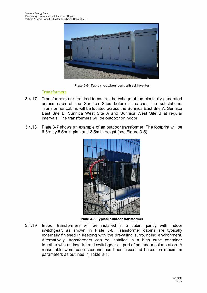
Plate 3-6. Typical outdoor centralised inverter
Transformers Transformers are required to control the voltage of the electricity generated
across each of the Sunnica Sites before it reaches the substations. Transformer cabins will be located across the Sunnica East Site A, Sunnica East Site B, Sunnica West Site A and Sunnica West Site B at regular intervals. The transformers will be outdoor or indoor.
Plate 3-7 shows an example of an outdoor transformer. The footprint will be 6.5m by 5.5m in plan and 3.5m in height (see Figure 3-5).
Plate 3-7. Typical outdoor transformer
Indoor transformers will be installed in a cabin, jointly with indoor switchgear, as shown in Plate 3-8. Transformer cabins are typically externally finished in keeping with the prevailing surrounding environment. Alternatively, transformers can be installed in a high cube container together with an inverter and switchgear as part of an indoor solar station. A reasonable worst-case scenario has been assessed based on maximum parameters as outlined in Table 3-1.
Sunnica Energy Farm Preliminary Environmental Information Report Volume 1: Main Report (Chapter 3: Scheme Description)
AECOM 3-13
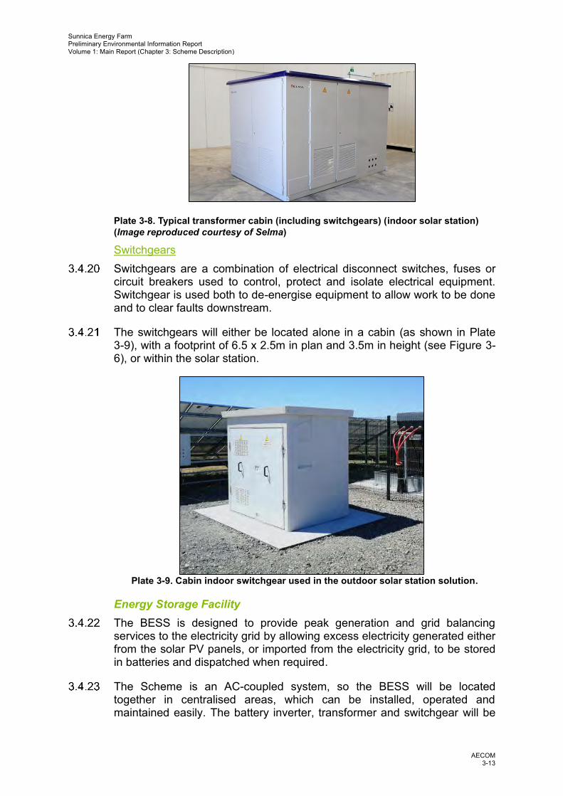
Plate 3-8. Typical transformer cabin (including switchgears) (indoor solar station) (Image reproduced courtesy of Selma)
Switchgears Switchgears are a combination of electrical disconnect switches, fuses or
circuit breakers used to control, protect and isolate electrical equipment. Switchgear is used both to de-energise equipment to allow work to be done and to clear faults downstream.
The switchgears will either be located alone in a cabin (as shown in Plate 3-9), with a footprint of 6.5 x 2.5m in plan and 3.5m in height (see Figure 3-6), or within the solar station.
Plate 3-9. Cabin indoor switchgear used in the outdoor solar station solution.
Energy Storage Facility The BESS is designed to provide peak generation and grid balancing
services to the electricity grid by allowing excess electricity generated either from the solar PV panels, or imported from the electricity grid, to be stored in batteries and dispatched when required.
The Scheme is an AC-coupled system, so the BESS will be located together in centralised areas, which can be installed, operated and maintained easily. The battery inverter, transformer and switchgear will be

Sunnica Energy Farm Preliminary Environmental Information Report Volume 1: Main Report (Chapter 3: Scheme Description)
AECOM 3-14
mounted on a concrete foundation as a single compound or monolith base. Three battery compounds will be required for the Scheme, as follows:
• Sunnica East Site A – located with Works Area E33; • Sunnica East Site B – located with Works Area E18; and • Sunnica West Site A – located with Works Area W17.
Plate 3-10 provides a view of a typical layout and Figures 3-1 and 3-2 show the location of the BESS compounds. The final layout of the BESS compounds will be determined during detailed design. The final layout may not utilise the whole of the Works Areas outline above; where this is the case PV modules may be installed within the areas not utilised by the BESS.
The batteries will be housed within containers of 15m by 5m in plan and up to a maximum 6m of height. Plate 3-10 shows a typical battery storage compound configuration. For scale comparisons, this example is similar in size to the Sunnica East Site A BESS compound (Works Area E33 in Figure 3-1).
The precise number of individual battery storage containers will depend upon the level of power capacity and duration of energy storage that the Scheme will require.
Each BESS will require a heating, ventilation and cooling (HVAC) system to ensure the efficiency of the batteries, which are integrated into the containers. This may involve a HVAC system that is external to the containerised unit located either on the top of the unit or attached to the side of the unit. If this uses air to heat and cool it will have a fan built into it that is powered by auxiliary power. The HVAC system is incorporated within the maximum parameters outlined in Table 3-1.
The Switchgear/Control Room operates, isolates and controls the exported power from the BESS. This will comprise a building of similar dimensions to the containers; either an adapted container or built from glass reinforced plastic (GRP), located within main BESS compound.
As the Scheme design develops, the likely configuration of equipment will be determined based upon environmental and technical factors. A reasonable worst-case scenario has been assessed based on maximum parameters as outlined in Table 3-1.

Sunnica Energy Farm Preliminary Environmental Information Report Volume 1: Main Report (Chapter 3: Scheme Description)
AECOM 3-15
Plate 3-10. Typical battery storage compound configuration (image reproduced courtesy of Fluence Energy).
Onsite Cabling Low voltage onsite electrical cabling is required to connect the PV modules
and BESS to inverters (typically via 1.5/1.8 kilovolt (kV) cables), and the inverters to the transformers onsite (typically via 0.6/1.0 kV cables). The dimension of the trenches will vary depending on the number of ducts they contain but will typically be up to 0.85m in width and up to 1.5m in depth.
Higher rated (high voltage) cables, 33 kV, are required between the transformers and the switchgears and from switchgears to the onsite substation. The dimension of the trenches will vary depending on the number of ducts they contain but will typically be up to 0.85m in width and up to 1.5m in depth.
High voltage 132 kV cables are required to export the electricity produced by the Sunnica East Site A, Sunnica East Site B, Sunnica West Site A, and Sunnica West Site B to the Burwell National Grid Substation Extension. Figure 3-7 illustrates the cross sections of the cable trenches. Figure 3-8 presents cross sections of cable crossings underneath watercourses.
Cabling between PV modules and the inverters will typically be above ground level (along a row of racks), fixed to the mounting structure, and then underground between racks and inverters. All other onsite cabling will be underground wherever possible.
Data cables will also be installed, typically alongside electrical cables in order to allow for the monitoring during operation, such as the collection of solar data from pyranometers 2.
2 An instrument used for measuring solar irradiance on a planar surface.

Sunnica Energy Farm Preliminary Environmental Information Report Volume 1: Main Report (Chapter 3: Scheme Description)
AECOM 3-16
The existing above-ground powerlines at the Sunnica West Site A are not proposed to be altered by the Scheme.
Onsite Substations Three substations will be located alongside the BESS at the Sunnica East
Site A, Sunnica East Site B and Sunnica West Site A. The substations will be sited within Works Area E33 (Sunnica East Site A), Works Area E18 (Sunnica East B) and Works Area W17 (Sunnica West Site A) (see Figures 3-1 and 3-2 for works area locations). The precise location will be determined through micro-siting during detailed design following the granting of the DCO consent.
These will consist of electrical infrastructure such as the transformers, switchgear and metering equipment required to facilitate the export of electricity from each respective site to the National Grid. The dimensions of each are as follows:
• Sunnica East A – 85m by 80m; • Sunnica East B – 85m by 55m; and • Sunnica West Site A – 85m by 130m.
Each substation will be up to 10m in height. Figures 3-9 (a and b), 3-10 (a and b) and 3-11 (a and b) illustrate the dimensions.
The substations will each include a control building, which will be up to 25 by 8m in plan, and up to 6m in height (see Figure 3-9a, 3-10a and 3-11a). These would be located within Works Areas E33, E18 and W17 for Sunnica East A, Sunnica East B and Sunnica West A, respectively. This will include office space and welfare facilities as well as operational monitoring and maintenance equipment. The control buildings will be a painted block building with external colours and finishes to be confirmed prior to construction.
Operational Offices/Warehouse Two operational office/warehouse blocks will be provided during operation
within Works Area E33 on Sunnica East A and within Works Area W17 on Sunnica West B, the precise location within the works areas will be determined through micro-siting during detailed design following granting of the DCO consent. The Sunnica East Site A office/warehouse will be up to 15m x 35m and 5m height and the Sunnica West Site A office/warehouse will be up to 25m x 40m and 8m height.
The offices will contain mobile welfare units, canteens, storage and waste skips, parking areas and warehouse facilities for the storage for spare parts.
Fencing, Security and Lighting A security fence will enclose the operational areas of the Sunnica East Site
A, Sunnica East B, Sunnica West Site A and Sunnica West Site B. The fence will be a ‘deer fence’, up to 2.5m in height (see Plate 3-11). Pole mounted internal facing closed circuit television (CCTV) systems will be deployed around the perimeter of the operational areas of each Site. It is

Sunnica Energy Farm Preliminary Environmental Information Report Volume 1: Main Report (Chapter 3: Scheme Description)
AECOM 3-17
anticipated that these will be 5m high. CCTV cameras will have fixed view sheds and will be aligned to face along the fence.
Plate 3-11. Typical deer security fence
To comply with British Standard (BS) EN 62271-1:2017 (Ref. 3-2), if
outdoor transformers are used, they will be surrounded by a secure wire mesh fence, as shown in Plate 3-12. This fence is will be a maximum of 2.5m in height.
Plate 3-12. Typical transformer compound fencing
In construction, during winter months, mobile lighting towers with a power
output of 8kVAs will be used. During operation, permanent lighting with motion sensors will be installed within the substations and BESS compounds. Security lighting (LED floodlights) with motion sensors will be installed within the BESS compounds, providing a maximum of 50 lux. Any night works required on the solar panels during operation will use mobile lighting towers.

Sunnica Energy Farm Preliminary Environmental Information Report Volume 1: Main Report (Chapter 3: Scheme Description)
AECOM 3-18
Site Access and Access Tracks The Scheme will have two main access points: one on Sunnica East B and
one on Sunnica West A. During construction, all small vehicles will access the DCO Site at these locations and park in the centralised car parks. Staff will then be distributed to the working area via minibus, or similar using internal tracks within the DCO Site. Sunnica East B will be accessed via the A11 and B1085 and the access to Sunnica West A will be via the Chippenham junction of the A11, to the north of junction 38 of the A14.
A number of secondary access points have been provided to access individual land parcels within the full DCO Site. Secondary access points for Sunnica East A and B will be from Elms Road northwest of the main access, Newmarket Road, Golf Links Road, Freckenham Road and Isleham Road (see Figure 3-12). Secondary access points for Sunnica West A and B will be from farm tracks, Chippenham Road, Dane Hill Road and Snailwell Road (see Figure 3-13). The Access Strategy which forms part of the Framework Construction Traffic Management Plan (CTMP) in Appendix 13B provides further information.
A number of the access roads are single carriageways; therefore, hedgerows may need to cut back and the access points may need to be widened/upgraded to assist with any wide loads, as described in the Transport Assessment in Appendix 13A.
Access arrangements to each Site is expected to remain consistent through construction, operation and any decommissioning activity.
Access tracks will be constructed within each of the Sites. These will be compacted stone tracks up to 3.5m wide with 1:2 gradient slopes on either side (Plate 3-13 and Plate 3-14). The primary access points will be wider, up to a maximum of 6m to facilitate two-way HGV traffic, and passing bays will be provided along internal access roads to ensure traffic does not impact the local highway network.
Plate 3-13. Cross section of access track.

Sunnica Energy Farm Preliminary Environmental Information Report Volume 1: Main Report (Chapter 3: Scheme Description)
AECOM 3-19
Plate 3-14. Example of an access path.
Surface water drainage The new drainage system will comprise of a series of interconnected
swales and infiltration ponds. The design will ensure that any effects from the new infrastructure (i.e. access tracks, cable trenches, hardstanding) on surface water drainage are mitigated. Figures 3-14 and 3-15 show the indicative drainage design system for the Sunnica East Site A and B and Sunnica West A and B Sites, respectively.
The detailed operational drainage design will be carried out pre-construction with the objective of ensuring that the existing level of drainage of the land is maintained. Infiltration drainage design will be in accordance with Building Research Establishment (BRE) Digest 365: Soakaway Design and Sewers for Adoption (Ref. 3-3).
The majority of the Sunnica East A, East B, West A and West B Sites are in Flood Zone 1. However, some areas are Flood Zones 2, 3a and 3b. These fluvial risk locations are in proximity to main rivers; the River Lark, Lee Brook and River Snail, as well as an ordinary watercourse running to the east of Chippenham.
Chapter 9: Water Environment provides a description of the flood risk and drainage design.
Electricity Export Connection to National Grid
The electricity generated by the Scheme is to be imported and exported via interface cables from the onsite substations to the Burwell National Grid Substation. The cable corridor will be directed across open countryside and require crossings of the railway, watercourses, various utilities, and roads.
The Burwell National Grid Substation is approximately 5.5km to the west of the Sunnica West Site B. A 132kV cable will be installed to connect the Sunnica East Site A, Sunnica East Site B, Sunnica West Site A and Sunnica West Site B to the Burwell National Grid Substation. The total

Sunnica Energy Farm Preliminary Environmental Information Report Volume 1: Main Report (Chapter 3: Scheme Description)
AECOM 3-20
length of the cable run for Grid Connection Route A will be approximately 7km, and 13km for Grid Connection Route B.
Up to three circuits3 may be required by the Scheme. The number of circuits will depend on several factors: the conductor material (copper or aluminium), the soil thermal resistivity, and the total capacity.
Circuits will be combined in a single trench with a width of up to 1.2m and a maximum depth of 2m. The working width which is required for material laydown and construction equipment will be up to a total of 35m depending on local conditions. In terms of installation, the cables will be laid directly into the trenches, or ducting will be installed, and the cables pulled through the ducting. Where the cable route encounters obstacles such as tree root systems, the width of the cable route (both permanent and temporary) may change locally.
Jointing pits will be required every 500m to 2000m to join sections of cable together. The dimensions of these are determined by how many circuits will be in the jointing pit. For three circuits, the dimensions of the jointing pit will be up to 20m by 5m, with a depth of 2m. The distance between jointing pits will be determined through the design process and is dependent on existing infrastructure along the cable route, cable specification and cable delivery limitations.
The cable route will need to cross a range of existing infrastructure such as major roads, minor roads and tracks, existing buried/underground utilities (such as medium and high-pressure gas mains), a railway, rivers, field drains and main drains. Open cut trenching will be primarily utilised for crossings. Trenchless techniques, such as boring4, micro-tunnelling5 or moling6 methods will be undertaken where the EIA or design concludes the need for an alternative to open trenching. Currently there are 10 proposed locations where an alternative to open trenching will be required across the Scheme.
The cable route corridor for Grid Connection A and Grid Connection B, shown in Figures 3-16a to 3-16d, is subject to an iterative design process. A range of constraints will determine the final optimal cable route details with a number of options being explored currently. These include physical, ecological, cultural heritage and human interactions, technical engineering, legal and commercial considerations.
An extension to the Burwell National Grid Substation will be required, including a transformer compound to transform the 132kV export voltage from the Sunnica East Sites and Sunnica West Sites to the National Grid 400kV connection voltage. The substation extension compound will have a
3 A circuit comprises three cables. It is anticipated the Scheme will employ a three circuits which will consists of 9 cables (three per circuit). 4 Boring is the process of enlarging a hole that has already been drilled (or cast) by means of a single-point cutting tool (or of a boring head containing several such tools), such as in boring a gun barrel or an engine cylinder. 5 Micro-tunnelling is a digging process that uses a remotely controlled microtunnel boring machine (MTBM) combined with the pipe jack-and-bore method to directly install pipes underground in a single pass. 6 During the moling process, a pneumatically-driven machine known as a mole forces its way through the soil along the desired path of the pipe.

Sunnica Energy Farm Preliminary Environmental Information Report Volume 1: Main Report (Chapter 3: Scheme Description)
AECOM 3-21
footprint of 65m by 50m in plan and 12m in height, as shown in Figure 3-17a and 3-17b. The three areas identified for Burwell National Grid substation extension are currently agricultural fields (see Figure 3-19). The preferred location is within National Grid land ownership to the east of the existing substation, adjacent to Weirs Drove, approximately 200m west of Burwell. The alternative two locations are to the north and north-west of the existing substation approximately 450 and 650m from Burwell, respectively.
Construction
Subject to being granted consent and following a final investment decision, the earliest construction will start is Autumn/Winter 2022, with planned operation by Spring 2025. Spring 2025 is the earliest date that the Scheme will be connected under the proposed agreement with National Grid.
A construction programme of approximately 24 months will be achieved if the Scheme was built in one continuous phase. This has been assessed within the PEI Report, as it is considered to be a worst case in terms environmental effects. The final programme will be dependent on the final Scheme design and potential environmental constraints on the timing of construction activities.
The construction of the cable route corridor will be undertaken in phases of approximately 4 months for each section. Boring, micro-tunnelling or moling sections will take between 8 and 12 weeks to construct.
Construction Activities The construction activities that are likely to be required are outlined below.
It is likely that a number of these activities will run in parallel with works being undertake on all sites at the same time.
Site Preparation and Civil Engineering Works The following activities would be required as part of these works:
• Preparation of land for construction, including localised site levelling (where required). The land levels changes will be localised, and will not be noticeable;
• Import of construction materials, plant and equipment to site; • Establishment of the perimeter fence; • Establishment of the construction compounds; • Construction of the internal access roads; and • Marking out the location of the Scheme infrastructure. Solar PV Array Construction
The following activities would be required to install the solar PV modules:
• Import of components to site; • Piling and erection of module mounting structures, with foundations to a
maximum depth of 3.5m (see Plate 3-15);

Sunnica Energy Farm Preliminary Environmental Information Report Volume 1: Main Report (Chapter 3: Scheme Description)
AECOM 3-22
Plate 3-15. Piling of module mounting structures.
• Mounting of modules. This will be undertaken by hand (see Plate 3-16);
Plate 3-16. Construction staff mounting solar PV modules by hand.
• Trenching and installation of electric cabling; • Transformer, inverter and switchgear foundation excavation and
construction; • Installation of transformers, inverters and switchgears. Cranes will be
used to lift equipment into position; and • Installation of control systems, monitoring and communication. Construction of Onsite Electrical Infrastructure
The following activities would be required to construct the onsite electrical infrastructure:
• Site preparation and civils for the three onsite substations;

Sunnica Energy Farm Preliminary Environmental Information Report Volume 1: Main Report (Chapter 3: Scheme Description)
AECOM 3-23
• Trenching and installation of electric cabling; • Pouring of the concrete foundation base; • Import of components to site. Cranes will be used to lift the components
into position; and • Installation of the substations. Construction of Cable Routes and Burwell Substation
The following activities would be required to construct the cable routes and Burwell Substation:
• Site preparation and civils for the Burwell substation; • Trenching and installation of electric cabling; and • Installation of the substation. BESS Construction:
The following activities would be required to construct the BESS:
• Installation of electric cabling; • Construction of foundations; • Import of components to site; • Installation of transformers; and • Installation of battery, transformers, inverters and switchgear. Testing and Commissioning;
Commissioning of the Scheme will include testing and commissioning of the process equipment. Commissioning of the PV infrastructure will involve mechanical and visual inspection, electrical and equipment testing, and commencement of electricity supply into the grid.
Landscaping and Habitat Creation See paragraphs 3.6.33 and 3.6.34 for details.
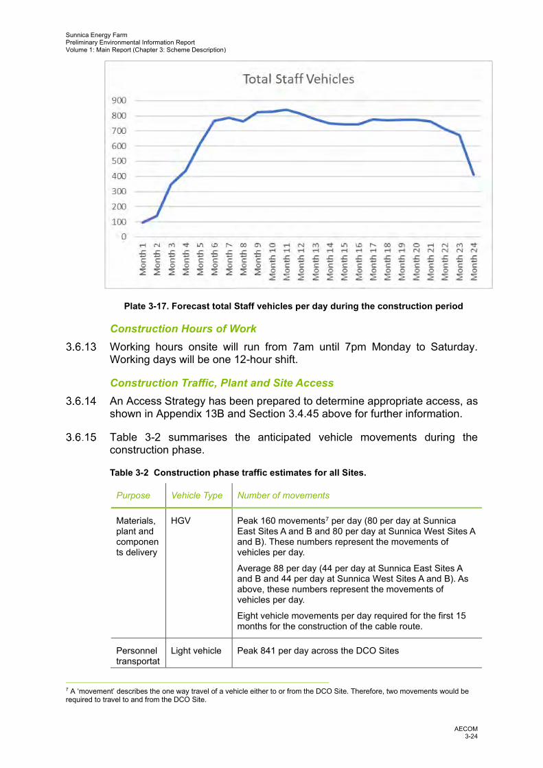
Construction Staff At the peak of construction, which is expected to be in month 11, an
average of 1,260 staff per day will be required to work across the Scheme, as shown in Plate 3-17. This number will be less at other times of the construction phase and less if construction was undertaken in phases.
Sunnica Energy Farm Preliminary Environmental Information Report Volume 1: Main Report (Chapter 3: Scheme Description)
AECOM 3-24
Plate 3-17. Forecast total Staff vehicles per day during the construction period
Construction Hours of Work Working hours onsite will run from 7am until 7pm Monday to Saturday.
Working days will be one 12-hour shift.
Construction Traffic, Plant and Site Access An Access Strategy has been prepared to determine appropriate access, as
shown in Appendix 13B and Section 3.4.45 above for further information.
Table 3-2 summarises the anticipated vehicle movements during the construction phase.
Table 3-2 Construction phase traffic estimates for all Sites.
Purpose Vehicle Type Number of movements
Materials, plant and components delivery
HGV Peak 160 movements7 per day (80 per day at Sunnica East Sites A and B and 80 per day at Sunnica West Sites A and B). These numbers represent the movements of vehicles per day.
Average 88 per day (44 per day at Sunnica East Sites A and B and 44 per day at Sunnica West Sites A and B). As above, these numbers represent the movements of vehicles per day.
Eight vehicle movements per day required for the first 15 months for the construction of the cable route.
Personnel transportat
Light vehicle Peak 841 per day across the DCO Sites
7 A ‘movement’ describes the one way travel of a vehicle either to or from the DCO Site. Therefore, two movements would be required to travel to and from the DCO Site.

Sunnica Energy Farm Preliminary Environmental Information Report Volume 1: Main Report (Chapter 3: Scheme Description)
AECOM 3-25
Purpose Vehicle Type Number of movements
ion Average 644 per day across the DCO Sites
Personnel transportation
Mini-bus Peak 54 per day across the DCO Sites
Average 41 per day across the DCO Sites
Fuel delivery
HGV 192 over the entire construction period, an average of 5 per month during construction.
Water delivery (industrial use)
HGV 30 over the entire construction period, an average of 1 per month during construction.
Water delivery (potable)
HGV 30 over the entire construction period, an average of 1 per month during construction.
Waste collection (general waste, hazardous waste and recyclables)
HGV 18,04 over the entire construction period, an average of 50 per month during construction.
Sewage and greywater collection
HGV 164 over the entire construction period, an average of 4 to 5 per month during construction.
Table 3-3 summarises the anticipated plant and machinery required during the construction phase.
Table 3-3 Construction plant and machinery numbers and type
Plant and machinery Sunnica East Site A and B Sunnica West Site A and B
Compact excavator 21 21
Mobile crane 7 5
Crawled Dozer 6 3
Excavator 11 9
Mini Excavator 4 3
Push press piling rig 12 12
Power generator 6 4

Sunnica Energy Farm Preliminary Environmental Information Report Volume 1: Main Report (Chapter 3: Scheme Description)
AECOM 3-26
Plant and machinery Sunnica East Site A and B Sunnica West Site A and B
Telehander 18 17
Truck 18 15
Vibrating roller 5 4
Wheeled Excavator 5 4
Compact excavator 21 21
Noise levels are provided in Chapter 11: Noise and Vibration.
Two car parks will be provided close to the strategic road network for construction workers (see Figure 3-18a and 3-18b). Construction workers will then be transported around site via mini-bus, or similar.
A Framework Construction Traffic Management Plan (CTMP) has been developed as part of the EIA which will guide the delivery of materials and staff onto the Scheme during the construction phase. This is presented in Chapter 13: Transport and Access and Appendix 13B for further details on construction traffic movement. It will be secured by requirement in the DCO.
A self-contained wheel wash per Site will be installed to be used by vehicles prior to exiting the Site onto the public highway if there is mud or debris on the construction site. For loads unable to use the fixed wheel wash, a localised wheel washing would be set up to cater for these individually and as required to ensure no detrimental effect to the highway.
Construction Compounds Construction compounds will be located within Sunnica East A, Sunnica
East B, Sunnica West A and Sunnica West B Sites, as shown in Figures 3-18a and 3-18b. The compounds will be approximately 6,000m2 and will contain offices, mobile welfare units, canteens, storage and waste skips, parking areas and space for storage, download and turning area. These construction compounds will also be used as compounds during the construction of the cable route corridor.
Storage of Construction Plant and Materials No long-term onsite storage of materials is required during the construction
phase. Materials will be delivered via HGVs at regular intervals to the construction compounds and transported directly to where it is required within the DCO Site using smaller LGVs.
Short term storage of materials and plant can be accommodated within the construction compound until it is required.

Sunnica Energy Farm Preliminary Environmental Information Report Volume 1: Main Report (Chapter 3: Scheme Description)
AECOM 3-27
Topsoil, spoil and other construction materials will be stored outside of the 1 in 100 year floodplain extent and only moved to the temporary works area immediately prior to use.
Spoil Management There will be no site wide reprofiling required; however, there may be a
need to flatten areas within the Sites. This is unlikely to create excess spoil and it is not expected that this would need to be removed from the DCO Site. Spoil material is only expected to be generated from cable trenches, temporary and permanent compounds, internal roads, BESS and substation compounds, and solar stations. During construction the spoil will be stored temporarily within designated areas adjacent to the cable route and within the construction compounds. The spoil will be utilised to backfill the cable trenches, reinstate the temporary construction compounds and any temporary access roads. Any excess spoil will be utilised across the DCO Site. No spoil will be removed from Site.
Construction Lighting During winter months, mobile lighting towers with a power output of 8kVAs
will be used during construction.
Energy Consumption An estimated 325m3 of fuel will be required during construction. Fuel for
machinery and generators will be delivered to site by a fuel truck and stored in an above ground fuel storage tank of 4–6 m³ capacity. The fuel storage tank will be sheltered, secured from unauthorised access and equipped with a spill protection bund capable of holding 110% of the volume of the tank. Spill kits will be available at the fuelling point and other strategic locations of the construction site to allow for prompt clean up to limit soil and water contamination. Construction workers will be trained in spill kit use.
Water Consumption An estimated 162.5m3 of water will be required during construction to
support welfare facilities onsite and other uses. The water will be transported to Site by road from an existing nearby licenced water abstraction source and stored on site in a tank of 5–10 m3 capacity.
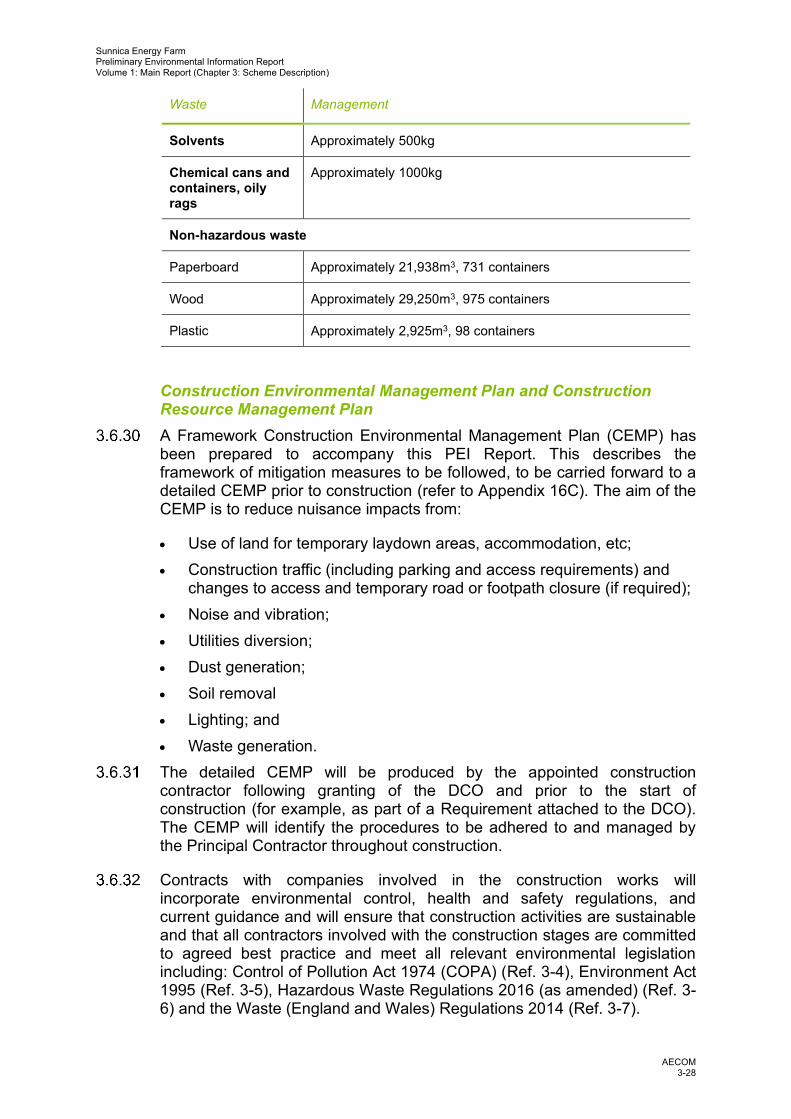
Waste Solid waste materials generated during construction will be segregated and
stored onsite in containers of 30m3 capacity prior to transport to an approved, licensed third party landfill and recycling facilities. Estimated waste arisings are summarised in Table 3-4.
Table 3-4 Estimated waste arisings during construction.
Waste Management
Hazardous waste
Paint Approximately 1000kg
Sunnica Energy Farm Preliminary Environmental Information Report Volume 1: Main Report (Chapter 3: Scheme Description)
AECOM 3-28
Waste Management
Solvents Approximately 500kg
Chemical cans and containers, oily rags
Approximately 1000kg
Non-hazardous waste
Paperboard Approximately 21,938m3, 731 containers
Wood Approximately 29,250m3, 975 containers
Plastic Approximately 2,925m3, 98 containers
Construction Environmental Management Plan and Construction Resource Management Plan
A Framework Construction Environmental Management Plan (CEMP) has been prepared to accompany this PEI Report. This describes the framework of mitigation measures to be followed, to be carried forward to a detailed CEMP prior to construction (refer to Appendix 16C). The aim of the CEMP is to reduce nuisance impacts from:
• Use of land for temporary laydown areas, accommodation, etc; • Construction traffic (including parking and access requirements) and
changes to access and temporary road or footpath closure (if required); • Noise and vibration; • Utilities diversion; • Dust generation; • Soil removal • Lighting; and • Waste generation.
The detailed CEMP will be produced by the appointed construction contractor following granting of the DCO and prior to the start of construction (for example, as part of a Requirement attached to the DCO). The CEMP will identify the procedures to be adhered to and managed by the Principal Contractor throughout construction.
Contracts with companies involved in the construction works will incorporate environmental control, health and safety regulations, and current guidance and will ensure that construction activities are sustainable and that all contractors involved with the construction stages are committed to agreed best practice and meet all relevant environmental legislation including: Control of Pollution Act 1974 (COPA) (Ref. 3-4), Environment Act 1995 (Ref. 3-5), Hazardous Waste Regulations 2016 (as amended) (Ref. 3-6) and the Waste (England and Wales) Regulations 2014 (Ref. 3-7).

Sunnica Energy Farm Preliminary Environmental Information Report Volume 1: Main Report (Chapter 3: Scheme Description)
AECOM 3-29
Site Reinstatement and Habitat Creation Following construction, a programme of site reinstatement and habitat
creation will commence. It is anticipated that the areas under the solar panels and areas outside of the developable areas will be planted with native grassland mix, and hedgerows and woodland will be planted in strategic locations to provide visual screening, as shown on Figure 3-1 and 3-2.
A Framework Landscape and Ecology Management Plan has been prepared to accompany this PEI Report (Appendix 10I). This document sets out the principles for how the land will be managed throughout the operational phase, following the completion of construction. A detailed Landscape and Ecology Management Plan will be produced following the granting of the DCO and prior to the start of construction (this will be secured by a Requirement attached to the DCO).
Operational Activities
During the operational phase, activity within the Scheme will be minimal and will be restricted principally to vegetation management, equipment maintenance and servicing, replacement of any components that fail, and monitoring. It is anticipated that maintenance and servicing would include the inspection, removal, reconstruction, refurbishment or replacement of faulty or broken equipment and adjusting and altering the solar module orientation to ensure the continued effective operation of the Scheme and improve its efficiency.
Along the cable route, operational activity will consist of routine inspections (schedule to be determined) and any reactive maintenance such as where a cable has been damaged.
It is anticipated that there will be up to 5 permanent staff onsite during the operational phase, with additional staff attending when required for maintenance and cleaning activities, up to 20 staff per day. Based on an occupancy of 1.5 persons per car as outlined in Chapter 13: Transport and Access, it is expected that there will be approximately 13 vehicles travelling to Site on a daily basis.
The design life of the Scheme is 40 years but the operational life of the equipment. If equipment is still operating successfully and safely, the developer may choose to operate beyond the Scheme’s design life. This is a common occurrence for generating stations; many stations operate beyond the design life if they are well maintained.
Decommissioning
The design life of the Scheme is expected to be at least 40 years, although the operational life may be longer than this; the condition of equipment will be reviewed at the end of the design life to determine whether it remains in a viable condition to continue operation after that time. Decommissioning is expected to take between 12 and 24 months and will be undertaken in phases. A Decommissioning Environmental Management Plan will be
Sunnica Energy Farm Preliminary Environmental Information Report Volume 1: Main Report (Chapter 3: Scheme Description)
AECOM 3-30
prepared prior to decommissioning and will be secured through a DCO Requirement.
When the operational phase ends, the Scheme will require decommissioning. All PV modules, mounting structures, structures, foundations, cabling, inverters and transformers will be removed and recycled or disposed of in accordance with good practice and market conditions at that time.
The effects of decommissioning are similar to, or often of a lesser magnitude than construction effects and will be considered in the relevant sections of the PEI Report. However, there can be a high degree of uncertainty regarding decommissioning as engineering approaches and technologies are likely to change over the operational life of the Scheme.
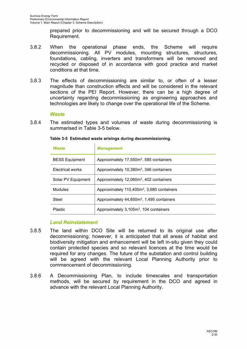
Waste The estimated types and volumes of waste during decommissioning is
summarised in Table 3-5 below.
Table 3-5 Estimated waste arisings during decommissioning.
Waste Management
BESS Equipment Approximately 17,550m3, 585 containers
Electrical works Approximately 10,380m3, 346 containers
Solar PV Equipment Approximately 12,060m3, 402 containers
Modules Approximately 110,400m3, 3,680 containers
Steel Approximately 44,850m3, 1,495 containers
Plastic Approximately 3,105m3, 104 containers
Land Reinstatement The land within DCO Site will be returned to its original use after
decommissioning; however, it is anticipated that all areas of habitat and biodiversity mitigation and enhancement will be left in-situ given they could contain protected species and so relevant licences at the time would be required for any changes. The future of the substation and control building will be agreed with the relevant Local Planning Authority prior to commencement of decommissioning.
A Decommissioning Plan, to include timescales and transportation methods, will be secured by requirement in the DCO and agreed in advance with the relevant Local Planning Authority.

Sunnica Energy Farm Preliminary Environmental Information Report Volume 1: Main Report (Chapter 3: Scheme Description)
AECOM 3-31
References
Ref. 3-1 Planning Inspectorate (2018); Advice Note 9: Using the Rochdale Envelope. Available at: https://infrastructure.planninginspectorate.gov.uk/wp-content/uploads/2013/05/Advice-note-9.-Rochdale-envelope-web.pdf [Date Accessed: 11/07/2020].
Ref. 3-2 British Standards Institute (2017) BS EN 62271-1:2017 High-voltage switchgear and controlgear. Common specifications for alternating current switchgear and controlgear.
Ref. 3-3 Building Research Establishment (BRE) (2012) Digest 365: Soakaway Design and Sewers for Adoption (7th Edition).
Ref. 3-4 HMSO (1974); Control of Pollution Act 1974. Available at: https://www.legislation.gov.uk/ukpga/1974/40/pdfs/ukpga_19740040_en.pdf [Date Accessed: 11/07/2020].
Ref. 3-5 HMSO (1995); Environment Act 1995. Available at: https://www.legislation.gov.uk/ukpga/1995/25/pdfs/ukpga_19950025_en.pdf [Date Accessed: 11/07/2020].
Ref. 3-6 HMSO (2016); The Hazardous Waste (Amendment) Regulations 2016. Available at: http://www.legislation.gov.uk/uksi/2016/336/made [Date Accessed: 11/07/2020].
Ref. 3-7 HMSO (2014); Waste (England and Wales) (Amendment) Regulations 2014. Available at: https://www.legislation.gov.uk/uksi/2014/656/contents/made [Date Accessed: 11/07/2020].

Sunnica Energy Farm Preliminary Environmental Information Report Volume 1: Main Report (Chapter 3: Scheme Description)
AECOM 3-32


