40
Electric Service Bulletin No. 759A – April 2014 Supplement to Specifications f or Electrical Installations Underground R esidential Distribution (URD) Installation and R esponsibility Guide
Electric Service Bulletin No. 759A – April 2014
Supplement to
Specifications for Electrical Installations
Underground Residential Distribution (URD)
Installation and Responsibility Guide
Liberty Utilities / Supplement to Specifications for Electrical Installations / ESB 759A April 2014
1 For the latest authorized version, please refer to the company’s website at http://www.libertyutilities.com/electricalspecifications.
Table of ContentsURD Specifications and Installation Guide Acknowledgement (Job Spec/Signoff Forms) .......................... 1
URD Specifications and Installation Guide Acknowledgement (Job Spec/Signoff Forms) .......................... 3
1.0 Scope ...................................................................................................................................................... 5
2.0 General Requirements ............................................................................................................................ 5
3.0 Type of Service ....................................................................................................................................... 5
4.0 Plans ....................................................................................................................................................... 6
5.0 Permits .................................................................................................................................................... 6
6.0 Division of Responsibility ........................................................................................................................ 7
7.0 Easements .............................................................................................................................................. 7
8.0 Trench Construction Requirements ........................................................................................................ 8
9.0 Trench and Conduit System Inspection .................................................................................................. 9
10.0 Conduit Installation ................................................................................................................................ 9
11.0 Transformer Box Pad Installation ........................................................................................................ 10
12.0 Transformer Secondary ...................................................................................................................... 11
13.0 Transformer Grounding and Bonding ................................................................................................. 11
14.0 Spacing of Boxpads, Pullboxes, and Handholes ................................................................................ 11
15.0 Proper Transformer Pad and Conduit Layout ..................................................................................... 12
Figure 15.0-1 Preferred Location of Equipment in Easement Area ....................................................... 12
Figure 15.0-2 Single Phase Padmount Transformer — Typical Layout .................................................. 13
15.0-3 Single Phase Padmount Transformer — Direct Burial Layout ..................................................... 13
16.0 Transformer Ground Grid Bonding ..................................................................................................... 14
Figure 16.0-1 Single Phase Padmount Transformer Ground Grid .......................................................... 14
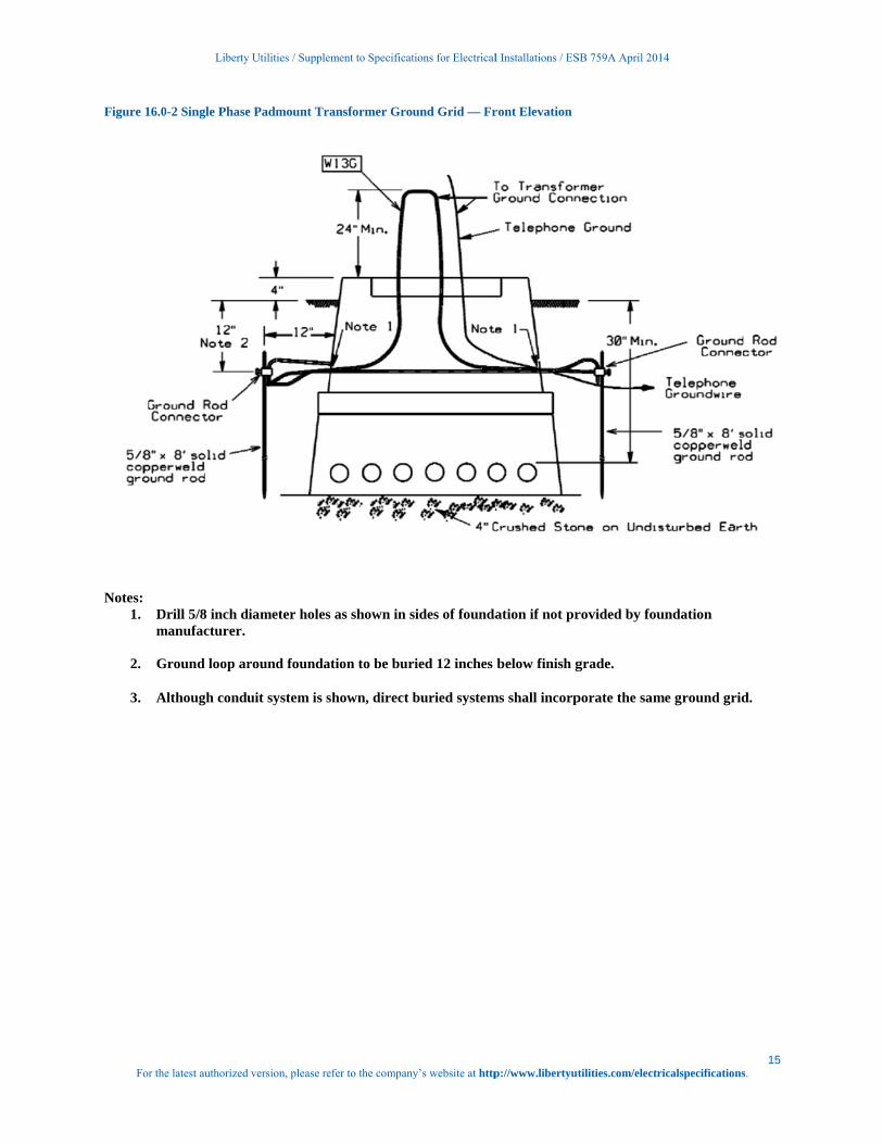
Figure 16.0-2 Single Phase Padmount Transformer Ground Grid — Front Elevation ............................ 15
17.0 Proper Transformer Pad and Conduit Installations ............................................................................. 16
17.0-1 Proper Conduit Bank Installation (Pre-Backfill) ............................................................................ 16
17.0-2 Proper Installation of Conduit with Pullbox used for Drainage (Pre-backfil) ................................ 16
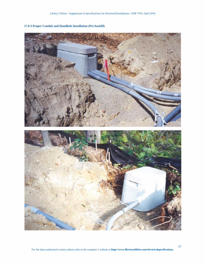
17.0-3 Proper Conduit and Handhole Installation (Pre-backfil) ............................................................... 17
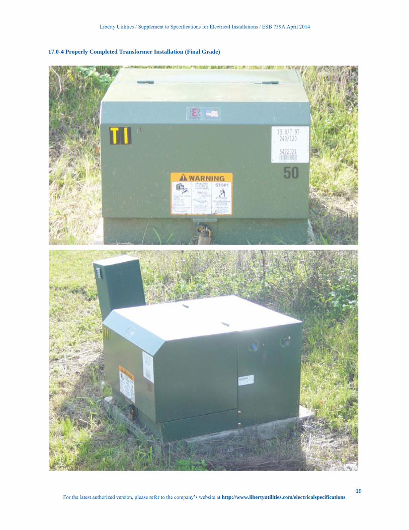
17.0-4 Properly Completed Transformer Installation (Final Grade) ........................................................ 18
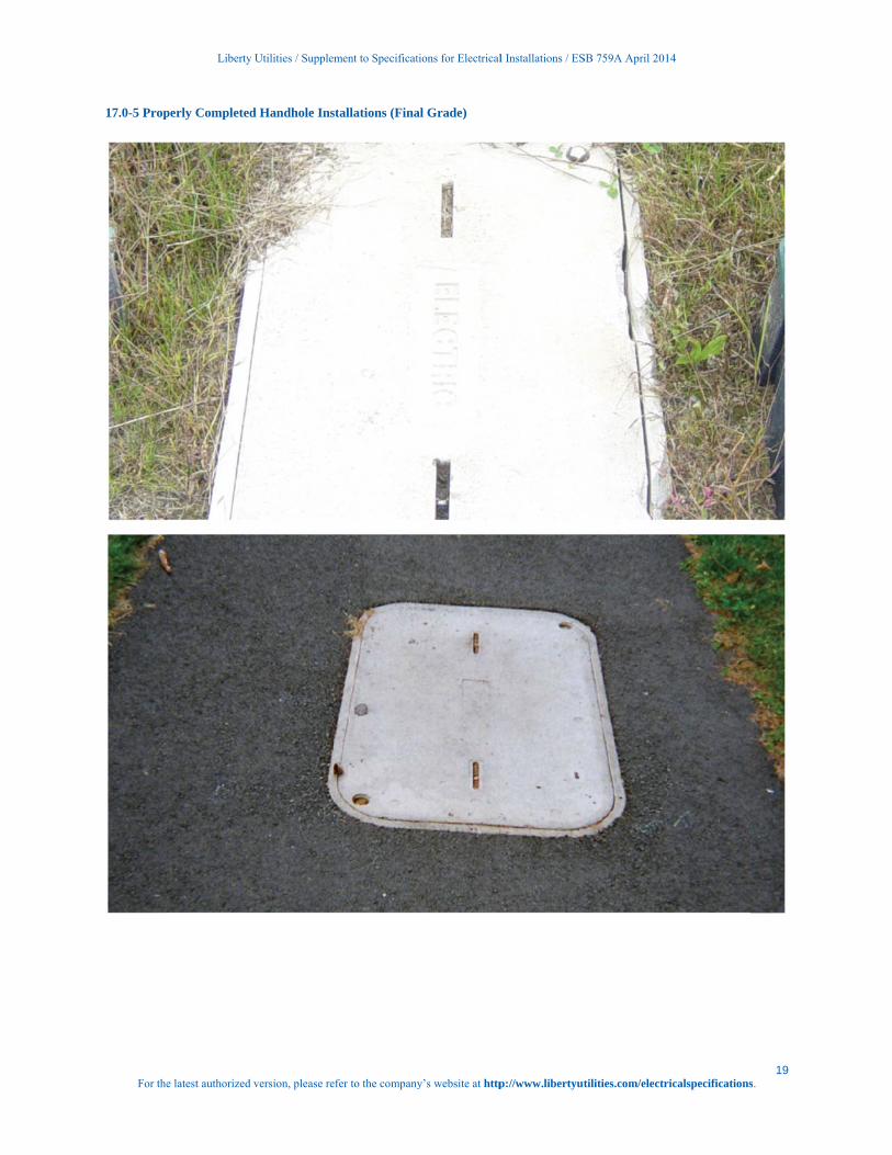
17.0-5 Properly Completed Handhole Installations (Final Grade) .......................................................... 19
18.0 Transformer Oil Containment .............................................................................................................. 20
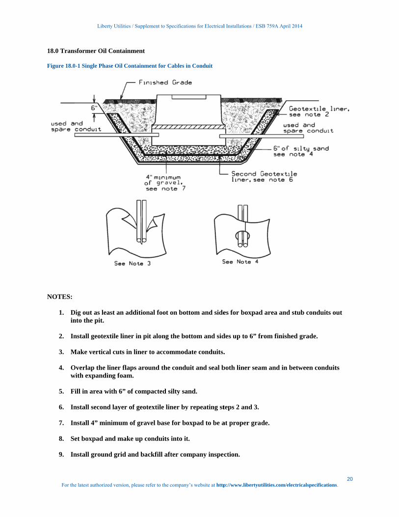
Figure 18.0-1 Single Phase Oil Containment for Cables in Conduit ....................................................... 20
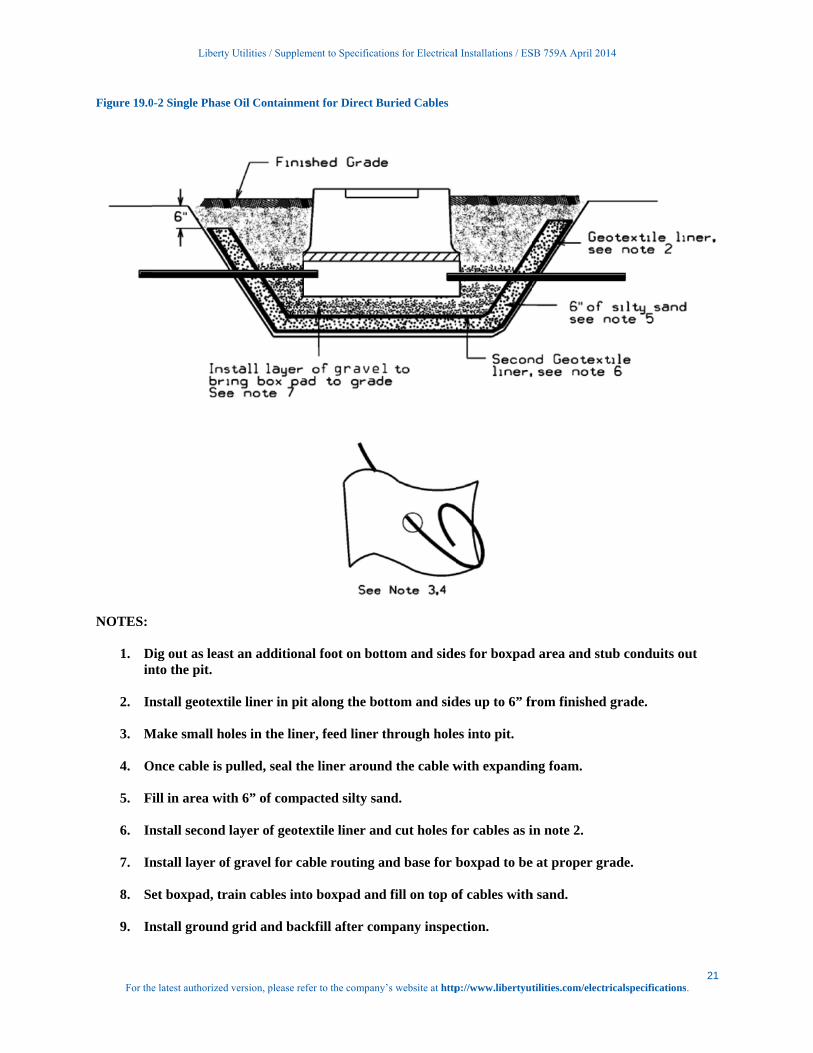
Figure 19.0-2 Single Phase Oil Containment for Direct Buried Cables .................................................. 21
19.0 Riser Pole ............................................................................................................................................ 23
20.0 Primary Cable Pull/Splice Box ............................................................................................................ 25
21.0 Trench Requirements .......................................................................................................................... 27
Figure 21.0-1 Typical Trenches ............................................................................................................... 28
22.0 Conduit Requirements ........................................................................................................................ 28

Liberty Utilities / Supplement to Specifications for Electrical Installations / ESB 759A April 2014
2 For the latest authorized version, please refer to the company’s website at http://www.libertyutilities.com/electricalspecifications.
22.1 Pulling Tape ........................................................................................................................................ 28
22.3 Communication Systems .................................................................................................................... 29
22.4 Non-Company Water, Gas and Sewer ............................................................................................... 29
23.0 Metering .............................................................................................................................................. 29
24.0 Easement Applications........................................................................................................................ 30
25.0 Approved Material – Underground Residential Installations ............................................................... 32
26.0 Job Checklists ..................................................................................................................................... 35
27.0 Revision History .................................................................................................................................. 36

Liberty Utilities / Supplement to Specifications for Electrical Installations / ESB 759A April 2014
1 For the latest authorized version, please refer to the company’s website at http://www.libertyutilities.com/electricalspecifications.
URD Specifications and Installation Guide Acknowledgement (Job Spec/Signoff Forms)
The requirements and specifications outlined in this guide book must be strictly followed. Any requirements not adhered to can pose safety problems, can be detrimental to the installed system and must be corrected before final acceptance. The Customer will bear full cost to make corrections to sub-standard installations. The Customer is responsible to provide enough lead time for the Company to design job, provide inspections and install Company equipment where applicable. Typical lead times are shown below. Lead-Time
Notes
Design and Layout
Eight weeks
Company receives all required plans, load data and easement information
Trench, Conduit and Equipment Inspection
Three days
Company inspector
Company Installation
Four weeks
After all inspections are approved and permits/ easements are procured
Material Pick up
10 Days
Company inspector
NOTE: The above times are estimates only. Project Title ______________________________________________________________________________ Location _________________________________________________________________________________ Owner/Developer __________________________________________________________________________ Customer’s Representative _____________________________________ Date _______________________ Company Representative _______________________________________ Date _______________________
Company’s Copy

Liberty Utilities / Supplement to Specifications for Electrical Installations / ESB 759A April 2014
2 For the latest authorized version, please refer to the company’s website at http://www.libertyutilities.com/electricalspecifications.

Liberty Utilities / Supplement to Specifications for Electrical Installations / ESB 759A April 2014
3 For the latest authorized version, please refer to the company’s website at http://www.libertyutilities.com/electricalspecifications.
URD Specifications and Installation Guide Acknowledgement (Job Spec/Signoff Forms)
The requirements and specifications outlined in this guide book must be strictly followed. Any requirements not adhered to can pose safety problems, can be detrimental to the installed system and must be corrected before final acceptance. The Customer will bear full cost to make corrections to sub-standard installations. The Customer is responsible to provide enough lead time for the Company to design job, provide inspections and install Company equipment where applicable. Typical lead times are shown below. Lead-Time
Notes
Design and Layout
Eight weeks
Company receives all required plans, load data and easement information
Trench, Conduit and Equipment Inspection
Three days
Company inspector
Company Installation
Four weeks
After all inspections are approved and permits/ easements are procured
Material Pick up
10 Days
Company inspector
NOTE: The above times are estimates only. Project Title ______________________________________________________________________________ Location _________________________________________________________________________________ Owner/Developer __________________________________________________________________________ Customer’s Representative _____________________________________ Date _______________________ Company Representative _______________________________________ Date _______________________
Customer’s Copy

Liberty Utilities / Supplement to Specifications for Electrical Installations / ESB 759A April 2014
4 For the latest authorized version, please refer to the company’s website at http://www.libertyutilities.com/electricalspecifications.

Liberty Utilities / Supplement to Specifications for Electrical Installations / ESB 759A April 2014
5 For the latest authorized version, please refer to the company’s website at http://www.libertyutilities.com/electricalspecifications.
1.0 Scope
The purpose of this specification is to define, interpret and clarify the scope of work and material dealing with providing service to URD’s and is a Supplement to Electrical System Bulletin (ESB) 750. It is important that the Specifications for Electrical Installations book (ESB 750) be obtained and referred to in conjunction with this supplement for these installations. Any reference to the Company in this specification shall mean the Liberty Utilities. Any reference to the Customer or Developer in this specification shall mean the property owner or the designee of the property owner of the URD.
2.0 General Requirements
All electrical wiring to be connected to the Company equipment shall be installed in accordance with one or all of the following:
Local Municipal Inspection Authority
State’s Electrical Code
National Electrical Code
National Electrical Safety Code
Applicable Distribution Construction Standards of the Company
Liberty Utilities’ Specifications for Electrical Installations
There shall be no attempt to deviate from either the Distribution Standards of the Company or the Company construction plan without the approval of the Company. Any specifications noted shall supersede the Specifications for Electrical Installations booklet unless otherwise approved by the Company. It is mandatory that the Customer and all parties involved attend a documented pre-construction meeting with a Company representative to discuss the project and ensure it a timely completion. A Company representative will make the necessary arrangements for the pre-construction meeting. Company representatives will also be available throughout the job life cycle to discuss construction problems when requested or during a field visit. References:
ESB 750 - Specifications for Electrical Installations
ESB 759B – UCD Installation and Responsibility Guide
All ESB’s are available at http://www.libertyutilities.com/electricalspecifications The Customer shall be responsible to have all electrical and physical design documents prepared and updated by a design professional, in accordance with Section 1.7 of ESB 750 for the trenching, conduit, transformer pad, and handhole installations.
3.0 Type of Service
Electric service shall be single phase, three wire, 120/240V supplied from a padmount transformer or handhole to be located on the Customer’s premises. The primary electrical service to the URD will be supplied from a pole or cable system owned by the Company.
Liberty Utilities / Supplement to Specifications for Electrical Installations / ESB 759A April 2014
6 For the latest authorized version, please refer to the company’s website at http://www.libertyutilities.com/electricalspecifications.
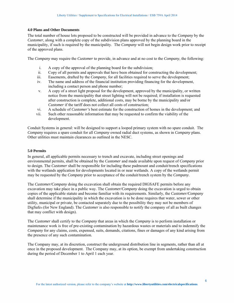
4.0 Plans and Other Documents
The total number of house lots proposed to be constructed will be provided in advance to the Company by the Customer, along with a complete copy of the subdivision plans approved by the planning board in the municipality, if such is required by the municipality. The Company will not begin design work prior to receipt of the approved plans. The Company may require the Customer to provide, in advance and at no cost to the Company, the following:
i. A copy of the approval of the planning board for the subdivision;
ii. Copy of all permits and approvals that have been obtained for constructing the development; iii. Easements, drafted by the Company, for all facilities required to serve the development; iv. The name and address of the financial institution providing financing for the development,
including a contact person and phone number; v. A copy of a street light proposal for the development, approved by the municipality, or written
notice from the municipality that street lighting will not be required; if installation is requested after construction is complete, additional costs, may be borne by the municipality and/or Customer if the tariff does not collect all costs of construction;
vi. A schedule of Customer’s best estimate for the construction of homes in the development; and vii. Such other reasonable information that may be requested to confirm the viability of the
development. Conduit Systems in general: will be designed to support a looped primary system with no spare conduit. The Company requires a spare conduit for all Company owned radial duct systems, as shown in Company plans. Other utilities must maintain clearances as outlined in the NESC.
5.0 Permits
In general, all applicable permits necessary to trench and excavate, including street openings and environmental permits, shall be obtained by the Customer and made available upon request of Company prior to design. The Customer shall be responsible for including these padmount and conduit/trench specifications with the wetlands application for developments located in or near wetlands. A copy of the wetlands permit may be requested by the Company prior to acceptance of the conduit/trench system by the Company. The Customer/Company doing the excavation shall obtain the required DIGSAFE permits before any excavation may take place in a public way. The Customer/Company doing the excavation is urged to obtain copies of the applicable statute and become familiar with its requirements. Similarly, the Customer/Company shall determine if the municipality in which the excavation is to be done requires that water, sewer or other utility, municipal or private, be contacted separately due to the possibility they may not be members of DigSafe® (for New England). The Customer is also responsible to notify the company of all as built changes that may conflict with design). The Customer shall certify to the Company that areas in which the Company is to perform installation or maintenance work is free of pre-existing contamination by hazardous wastes or materials and to indemnify the Company for any claims, costs, expensed, suits, demands, citations, fines or damages of any kind arising from the presence of any such contamination. The Company may, at its discretion, construct the underground distribution line in segments, rather than all at once in the proposed development. The Company may, at its option, be exempt from undertaking construction during the period of December 1 to April 1 each year.

Liberty Utilities / Supplement to Specifications for Electrical Installations / ESB 759A April 2014
7 For the latest authorized version, please refer to the company’s website at http://www.libertyutilities.com/electricalspecifications.
6.0 Division of Responsibility
The division of ownership and responsibility shall be as outlined below. Typical installation specifications to reflect installation practices are shown in the back of this guide. New Hampshire
a. The Company will:
i. Develop the plan to provide underground electric service, ii. Supply a list of approved manufacturers and their part numbers for equipment to be
supplied by the customer, (See Pages 32 – 34) iii. Designate the location of all Company owned equipment, iv. Provide Company owned street light foundations and any cable-in-conduit required for
street light applications, v. Provide, install, own and maintain all transformers, Company owned street lights,
primary and secondary cable, except services, vi. Make all connections to Company equipment,
vii. Inspect the underground conduit system, equipment foundations and ground grids installed by the Customer, prior to backfilling and before Company acceptance of conduit system,
viii. Determine if oil containment shall be required for padmount transformer installation,
b. The Customer, at no cost to the Company, will:
i. Provide, prior to the start of the Company’s construction, all applicable documents required for the Company to prepare easements for its facilities to be installed on private property,
ii. Install foundations and conduit, provided by the Company, for Company owned street lights, which locations have been approved by the local municipality,
iii. Provide and install all required handholes, boxpads, pull/splice boxes, grounding systems, and conduit including spacers, galvanized conduit and sweeps for riser poles including bonding clamps and neutral tap, glue and pulling tape, etc. as indicated on the Company’s plan and related construction documents,
iv. Supply copies of all invoices, when requested, indicating manufacturer and part number for all such equipment above; equipment that is not approved shall not be used without the prior written consent of the Company,
v. Install, own and maintain all secondary services and service conduit from the Company’s equipment to each designated meter location,
vi. Turn over ownership of the conduit system, excluding the service conduit, to the Company upon inspection and acceptance of the conduit system by the Company,
vii. Provide and install material for oil containment under padmounted transformers where required.
7.0 Easements
In general, Company-owned equipment shall not be installed on the Customer’s property prior to the execution of suitable easement(s). The Customer will have to provide to the Company (for the purposes of securing an easement) the following items, including but not limited to:
Copy of property deed showing: owner, date, book number, page number county registry, and survey
and/or plan of record, if available.
Note: When electronic maps are used, the Customer must consult the Company for submittal.
Copy of mortgages showing: holder, date, book number, page number and county registry.

Liberty Utilities / Supplement to Specifications for Electrical Installations / ESB 759A April 2014
8 For the latest authorized version, please refer to the company’s website at http://www.libertyutilities.com/electricalspecifications.
Copy of any applicable trusts showing: date, book number, page number and county registry, and who
is authorized to sign legal documents on behalf of the Trust.
Easement application forms are located on Page 31. Refer to Sections 3.1.3 and 4.1.1 in ESB 750 for further easement requirements applicable to the Applicant or Customer.
8.0 Trench Construction Requirements
a. Layout and Grading i. Final grades shall be established and the binder coat installed, and easement boundaries,
street, lot and trench lines staked by the Customer before any trenching is started (except for Company inspected road crossings).
b. Trenching and Backfilling
i. The Customer shall adhere to the construction plan specifying trench locations and depths, with any deviation being subject to approval by the Company.
ii. Minimum burial depths specified for all electrical conduit and direct burial trenches shall be maintained during all phases of construction. Temporary mechanical protection over buried conduit during construction to prevent conduit crushing or damage due to unusually heavy construction equipment shall be the responsibility of the Customer.
iii. Trench detail shown in attached Company Standards shall be adhered to. The trench bottom shall be solid, undisturbed earth. Earth showing signs of peat, cinders, rubble or any conditions not suitable for a stable foundation shall be reported to the Company Representative for recommendation. Pockets of unsuitable soil shall be replaced with compacted sand.
iv. For work done by Customer, a Company representative shall be notified in advance of the
backfilling of any electric facility, i.e., conduit, foundation, handhold, pull-box, cable-in-conduit, grounding, cables, etc.
If any facility is backfilled without the Company’s prior approval, the Company reserves the right to require re-excavation of the facility.
aa. Sand for conduit installation - A minimum of three inches of sand shall be placed, under, beside, around and on top of all electric conduits. The sand shall pass through 3/8 inch mesh screen and shall not contain any sharp stones. Sand shall be placed and suitably tamped over installed conduit in reasonably small quantities (not a front end loader bucketful all at once) to avoid conduit damage. Sand shall be evenly distributed between and around all electric conduits.
v. Remainder of backfill shall not contain stones greater than once inch and shall not
contain ashes, cinders, shell, or frozen material,
vi. Trenches shall be immediately backfilled following cable or conduit system inspection and approval by authorized Company representative,
vii. Backfilling shall be accomplished in a continuous manner from one terminal, i.e., riser
pole, foundation, handhold, etc. to the next,
viii. Backfilling shall not take place over any open-ended (unplugged) conduits,
Liberty Utilities / Supplement to Specifications for Electrical Installations / ESB 759A April 2014
9 For the latest authorized version, please refer to the company’s website at http://www.libertyutilities.com/electricalspecifications.
ix. Company approved red cable “Warning” or “Marking” tape shall be installed in the
trench 12 inches below finished grade and directly above the cable or conduit.
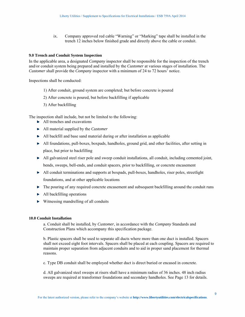
9.0 Trench and Conduit System Inspection
In the applicable area, a designated Company inspector shall be responsible for the inspection of the trench and/or conduit system being prepared and installed by the Customer at various stages of installation. The Customer shall provide the Company inspector with a minimum of 24 to 72 hours’ notice. Inspections shall be conducted:
1) After conduit, ground system are completed; but before concrete is poured
2) After concrete is poured, but before backfilling if applicable
3) After backfilling
The inspection shall include, but not be limited to the following:
All trenches and excavations
All material supplied by the Customer
All backfill and base sand material during or after installation as applicable
All foundations, pull-boxes, boxpads, handholes, ground grid, and other facilities, after setting in
place, but prior to backfilling
All galvanized steel riser pole and sweep conduit installations, all conduit, including cemented joint,
bends, sweeps, bell-ends, and conduit spacers, prior to backfilling, or concrete encasement
All conduit terminations and supports at boxpads, pull-boxes, handholes, riser poles, streetlight
foundations, and at other applicable locations
The pouring of any required concrete encasement and subsequent backfilling around the conduit runs
All backfilling operations
Witnessing mandrelling of all conduits
10.0 Conduit Installation
a. Conduit shall be installed, by Customer, in accordance with the Company Standards and Construction Plans which accompany this specification package. b. Plastic spacers shall be used to separate all ducts where more than one duct is installed. Spacers shall not exceed eight foot intervals. Spacers shall be placed at each coupling. Spacers are required to maintain proper separation from adjacent conduits and to aid in proper sand placement for thermal reasons. c. Type DB conduit shall be employed whether duct is direct buried or encased in concrete. d. All galvanized steel sweeps at risers shall have a minimum radius of 36 inches. 48 inch radius sweeps are required at transformer foundations and secondary handholes. See Page 13 for details.
Liberty Utilities / Supplement to Specifications for Electrical Installations / ESB 759A April 2014
10 For the latest authorized version, please refer to the company’s website at http://www.libertyutilities.com/electricalspecifications.
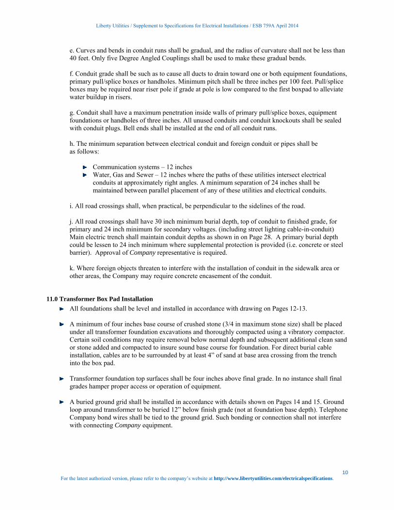
e. Curves and bends in conduit runs shall be gradual, and the radius of curvature shall not be less than 40 feet. Only five Degree Angled Couplings shall be used to make these gradual bends. f. Conduit grade shall be such as to cause all ducts to drain toward one or both equipment foundations, primary pull/splice boxes or handholes. Minimum pitch shall be three inches per 100 feet. Pull/splice boxes may be required near riser pole if grade at pole is low compared to the first boxpad to alleviate water buildup in risers. g. Conduit shall have a maximum penetration inside walls of primary pull/splice boxes, equipment foundations or handholes of three inches. All unused conduits and conduit knockouts shall be sealed with conduit plugs. Bell ends shall be installed at the end of all conduit runs. h. The minimum separation between electrical conduit and foreign conduit or pipes shall be as follows:
Communication systems – 12 inches Water, Gas and Sewer – 12 inches where the paths of these utilities intersect electrical
conduits at approximately right angles. A minimum separation of 24 inches shall be maintained between parallel placement of any of these utilities and electrical conduits.
i. All road crossings shall, when practical, be perpendicular to the sidelines of the road. j. All road crossings shall have 30 inch minimum burial depth, top of conduit to finished grade, for primary and 24 inch minimum for secondary voltages. (including street lighting cable-in-conduit) Main electric trench shall maintain conduit depths as shown in on Page 28. A primary burial depth could be lessen to 24 inch minimum where supplemental protection is provided (i.e. concrete or steel barrier). Approval of Company representative is required. k. Where foreign objects threaten to interfere with the installation of conduit in the sidewalk area or other areas, the Company may require concrete encasement of the conduit.
11.0 Transformer Box Pad Installation
All foundations shall be level and installed in accordance with drawing on Pages 12-13.
A minimum of four inches base course of crushed stone (3/4 in maximum stone size) shall be placed under all transformer foundation excavations and thoroughly compacted using a vibratory compactor. Certain soil conditions may require removal below normal depth and subsequent additional clean sand or stone added and compacted to insure sound base course for foundation. For direct burial cable installation, cables are to be surrounded by at least 4” of sand at base area crossing from the trench into the box pad.
Transformer foundation top surfaces shall be four inches above final grade. In no instance shall final
grades hamper proper access or operation of equipment.
A buried ground grid shall be installed in accordance with details shown on Pages 14 and 15. Ground loop around transformer to be buried 12” below finish grade (not at foundation base depth). Telephone Company bond wires shall be tied to the ground grid. Such bonding or connection shall not interfere with connecting Company equipment.

For the
Req
Use
T
In
in
12.0 Trans
Customer approved bsize of secNo more twith five ftransforme
13.0 Trans
The grounfinished grconduit an Two ⅝inc12” belowground gribe made wweld") shafor the grotransforme
14.0 Spaci
All commuAlso, com
NOTEreasonthey ha
Liberty
e latest authorized
Retaining wallsquipment, suc
Upon completinealed with a su
ransformer fo
n some locationstallation pro
sformer Secon
secondary serby the wire incondary cable than five seconfeet of slack coer.
sformer Grou
nd grid shall berade and locat
nd leave three
h diameter, eiw finished gradid is to be com
with compressiall be an accepound grid conner.
ing of Boxpad
unication boxmmunication eq
E: In most instnably level. Alsamper door op
y Utilities / Supple
d version, please re
s or other devih as transformng the installauitable matchi
undation shall
ons oil containcedure.
ndary
rvice wires entnspector or AH
to be physicalndary servicesoiled inside th
unding and Bo
e #2, bare, softed around thefeet of wire ab
ight feet long cde. Leave the gmplete and bacion connectorsptable alternatnections to the
ds, Pull/Splice
es shall be a mquipment shal
tances, the Coso, all retaininpenings or pla
ment to Specificat
efer to the company
ices shall be inmers due to shaation of the traing cover.
l be completel
nment may be
tering the boxHJ (Authority Hlly connected s shall be connhe pad in order
onding
ft drawn, 7 strae transformer pbove pad for g
copper weld gground rods anckfilled prior ts as shown onive to a compr
e ground rods.
boxes, and Ha
minimum of 2l not be placed
ompany shall rng walls shall
acement of sucthe
tions for Electrical
y’s website at http
nstalled wherearp drop-off o
ansformer foun
ly backfilled p
required for b
x pad shall be iHaving Jurisdto the Compan
nected at any Cr to reach to th
and copper wipad as shown grounding tran
ground rods annd grid exposeto energizing tn Pages 14 andression conne The Company
andholes
’ away from ad in front of an
require that eqfall outside of
ch equipment. e Company.
l Installations / ES
p://www.libertyut
e slopes exist tor rise. ndation, the to
prior to comm
box pad install
in accordancediction) of the ny's pad-mounCompany supphe secondary c
ire. The wire son Page 14. B
nsformer.
nd approved coed until inspecthe transformed 15. Howeverction. Bolted
ny shall install
any Company bny Company e
quipment easef equipment eaRetaining wal
SB 759A April 201
tilities.com/electr
that would und
op opening sha
mencing any ca
lation, Pages 2
with the NECtown or city innted transformply point. Cabconnection po
shall be installBond to all exp
onnectors shalcted by the Coer. Connectionr exothermic wconnectors arethe ground tap
boxpad, pullbequipment.
ements on privasements and ll design shall
14
ricalspecifications
dermine or co
all be securely
able pulling.
20 and 21 show
C and shall benvolved. Max
mer is 500 kcmbles shall be leoints on the
led 12 inches bposed metallic
ll be installed ompany. The ns to ground gwelding ("cade only acceptaps onto the
box or handhol
vate property bin no case sha
l be approved
11 s.
over
y
w
ximum mil. eft
below c
to
grid to
able
le.
be all by
For the
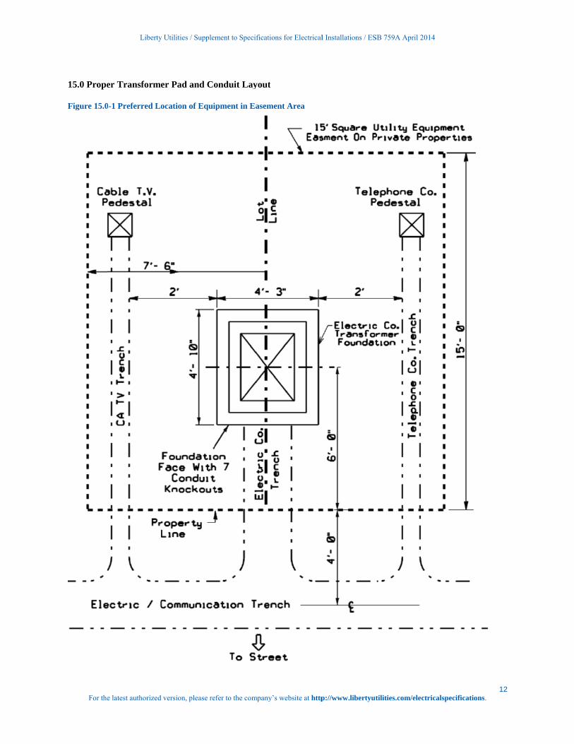
15.0 Prope
Figure 15.0
Liberty
e latest authorized
er Transform
0-1 Preferred Lo
y Utilities / Supple
d version, please re
er Pad and Co
ocation of Equi
ment to Specificat
efer to the company
onduit Layout
ipment in Easem
tions for Electrical
y’s website at http
t
ment Area
l Installations / ES
p://www.libertyut
SB 759A April 201
tilities.com/electr
14
ricalspecifications12
s.
For the
Figure 15.0
15.0-3 Sing
Liberty
e latest authorized
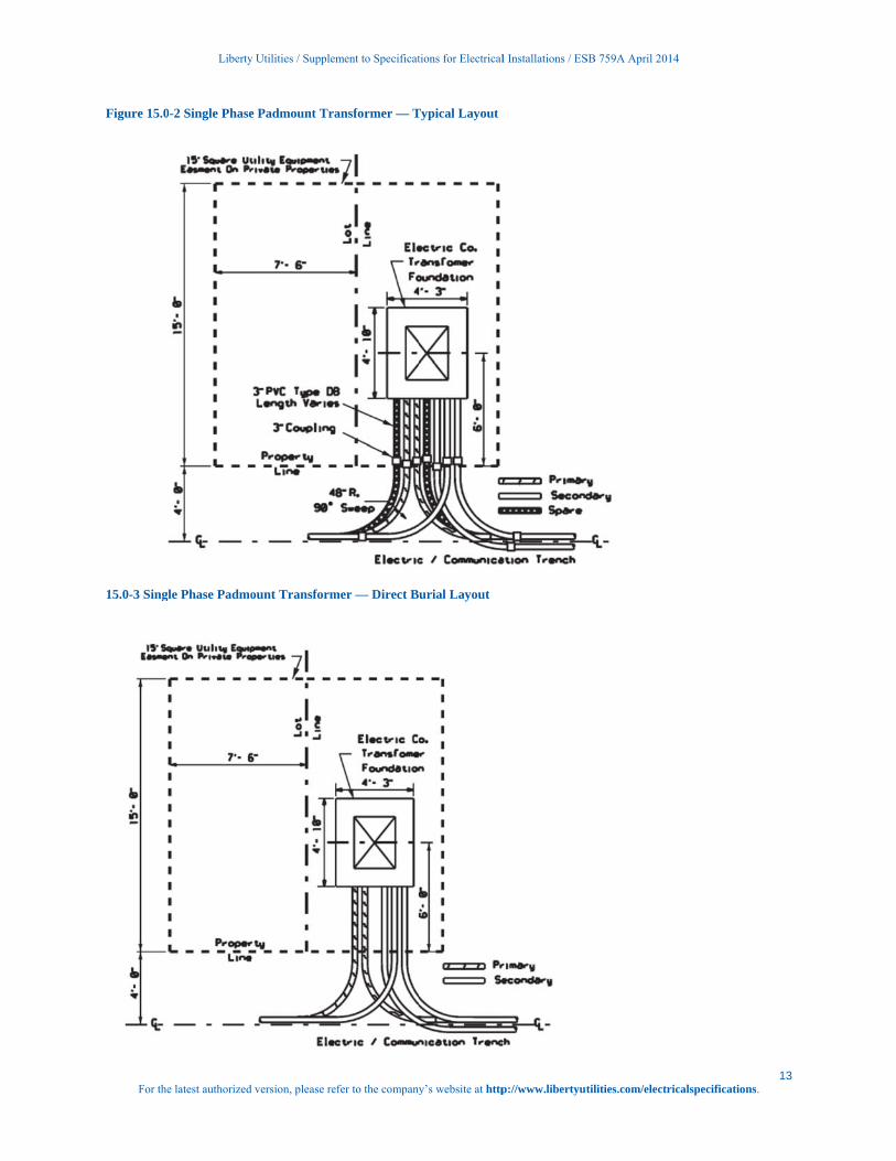
0-2 Single Phase
gle Phase Padmo
y Utilities / Supple
d version, please re
e Padmount Tra
ount Transform
ment to Specificat
efer to the company
ansformer — T
mer — Direct B
tions for Electrical
y’s website at http
Typical Layout
urial Layout
l Installations / ES
p://www.libertyut
SB 759A April 201
tilities.com/electr
14
ricalspecifications13
s.
For the
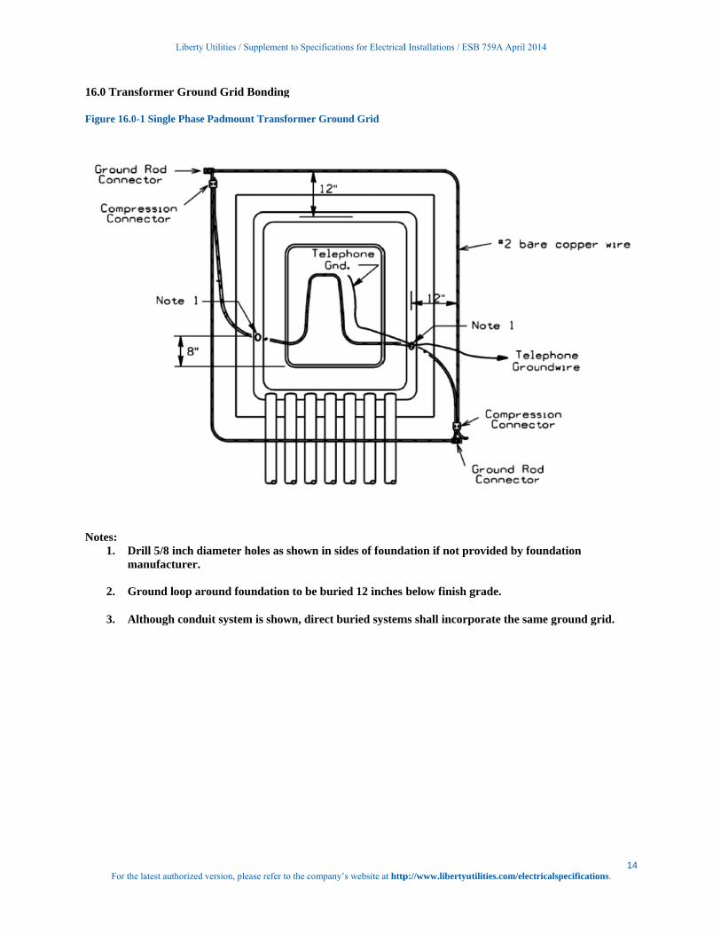
16.0 Trans
Figure 16.0
Notes:
1. Dm
2. G
3. A
Liberty
e latest authorized
sformer Grou
0-1 Single Phase
Drill 5/8 inch dmanufacturer.
Ground loop ar
Although condu
y Utilities / Supple
d version, please re
und Grid Bond
e Padmount Tra
diameter holes
round founda
uit system is s
ment to Specificat
efer to the company
ding
ansformer Grou
as shown in s
tion to be bur
shown, direct b
tions for Electrical
y’s website at http
und Grid
sides of founda
ried 12 inches
buried system
l Installations / ES
p://www.libertyut
ation if not pr
below finish g
ms shall incorp
SB 759A April 201
tilities.com/electr
rovided by fou
grade.
porate the sam
14
ricalspecifications
undation
me ground grid
14 s.
d.
For the
Figure 16.0
Notes:
1. Dm
2. G
3. A
Liberty
e latest authorized
0-2 Single Phase
Drill 5/8 inch dmanufacturer.
Ground loop ar
Although condu
y Utilities / Supple
d version, please re
e Padmount Tra
diameter holes
round founda
uit system is s
ment to Specificat
efer to the company
ansformer Grou
as shown in s
tion to be bur
shown, direct b
tions for Electrical
y’s website at http
und Grid — Fr
sides of founda
ried 12 inches
buried system
l Installations / ES
p://www.libertyut
ront Elevation
ation if not pr
below finish g
ms shall incorp
SB 759A April 201
tilities.com/electr
rovided by fou
grade.
porate the sam
14
ricalspecifications
undation
me ground grid
15 s.
d.

For the
17.0 Prope
17.0-1 Prop
17.0-2 Prop
Liberty
e latest authorized
er Transform
per Conduit Ban
per Installation
y Utilities / Supple
d version, please re
er Pad and Co
nk Installation
of Conduit wit
ment to Specificat
efer to the company
onduit Installa
(Pre-Backfill)
h Pullbox used
tions for Electrical
y’s website at http
ations
for Drainage (P
l Installations / ES
p://www.libertyut
Pre-backfil)
SB 759A April 201
tilities.com/electr
14
ricalspecifications
16 s.
For the
17.0-3 Prop
Liberty
e latest authorized
per Conduit and
y Utilities / Supple
d version, please re
d Handhole Ins
ment to Specificat
efer to the company
tallation (Pre-b
tions for Electrical
y’s website at http
backfil)
l Installations / ES
p://www.libertyut
SB 759A April 201
tilities.com/electr
14
ricalspecifications17
s.
For the
17.0-4 Prop
Liberty
e latest authorized
perly Completed
y Utilities / Supple
d version, please re
d Transformer
ment to Specificat
efer to the company
Installation (Fi
tions for Electrical
y’s website at http
inal Grade)
l Installations / ES
p://www.libertyut
SB 759A April 201
tilities.com/electr
14
ricalspecifications18
s.
For the
17.0-5 Prop
Liberty
e latest authorized
perly Completed
y Utilities / Supple
d version, please re
d Handhole Ins
ment to Specificat
efer to the company
stallations (Fina
tions for Electrical
y’s website at http
al Grade)
l Installations / ES
p://www.libertyut
SB 759A April 201
tilities.com/electr
14
ricalspecifications19
s.
For the
18.0 Trans
Figure 18.0
NOTES:
1. Din
2. In
3. M
4. O
w
5. F
6. In
7. In
8. Se
9. In
Liberty
e latest authorized
sformer Oil C
0-1 Single Phase
Dig out as leasnto the pit.
nstall geotexti
Make vertical
Overlap the linwith expandin
ill in area wit
nstall second
nstall 4” mini
et boxpad an
nstall ground
y Utilities / Supple
d version, please re
Containment
e Oil Containme
st an addition
ile liner in pit
cuts in liner t
ner flaps aroug foam.
th 6” of comp
layer of geote
imum of grav
d make up co
d grid and bac
ment to Specificat
efer to the company
ent for Cables i
nal foot on bot
t along the bo
to accommod
und the condu
pacted silty sa
extile liner by
vel base for bo
onduits into it
ckfill after co
tions for Electrical
y’s website at http
in Conduit
ttom and side
ottom and sid
date conduits.
uit and seal b
and.
y repeating st
oxpad to be a
t.
mpany inspec
l Installations / ES
p://www.libertyut
es for boxpad
des up to 6” fr
.
both liner sea
teps 2 and 3.
at proper grad
ction.
SB 759A April 201
tilities.com/electr
d area and stu
rom finished
m and in betw
de.
14
ricalspecifications
ub conduits o
grade.
ween conduit
20 s.
ut
ts
For the
Figure 19.0
NOTES:
1. Din
2. In
3. M
4. O
5. F
6. In
7. In
8. Se
9. In
Liberty
e latest authorized
0-2 Single Phase
Dig out as leasnto the pit.
nstall geotexti
Make small ho
Once cable is p
ill in area wit
nstall second
nstall layer of
et boxpad, tr
nstall ground
y Utilities / Supple
d version, please re
e Oil Containme
st an addition
ile liner in pit
oles in the line
pulled, seal th
th 6” of comp
layer of geote
f gravel for ca
ain cables int
d grid and bac
ment to Specificat
efer to the company
ent for Direct B
nal foot on bot
t along the bo
er, feed liner
he liner aroun
pacted silty sa
extile liner an
able routing a
to boxpad and
ckfill after co
tions for Electrical
y’s website at http
Buried Cables
ttom and side
ottom and sid
through hole
nd the cable w
and.
nd cut holes fo
and base for b
d fill on top o
mpany inspec
l Installations / ES
p://www.libertyut
es for boxpad
des up to 6” fr
es into pit.
with expandin
for cables as i
boxpad to be
of cables with
ction.
SB 759A April 201
tilities.com/electr
d area and stu
rom finished
ng foam.
in note 2.
e at proper gr
h sand.
14
ricalspecifications
ub conduits o
grade.
rade.
21 s.
ut
Liberty Utilities / Supplement to Specifications for Electrical Installations / ESB 759A April 2014
22 For the latest authorized version, please refer to the company’s website at http://www.libertyutilities.com/electricalspecifications.
Geo-textile Liner Generic name is: 16 oz. polypropylene geotextile. Also called filter fabric weighing 16 oz./square yard. Brand names / Suppliers are: AME1680 available from American Engineering Fabrics (AEF), Inc. (Emphasize polypropylene not polyester) New Bedford, MA 1-617-965-0007 / 1-800-770-2666 or from Vellano Bros. Lancaster, NY 1-716-684-7222 Several other locations in New York, Massachusetts, Rhode Island and New Hampshire www.vellano.com Synthetic Industries ST 160 available from Spartan Mills Inc Spartanburg, NC 1-803-576-2353 Carthage Mills FX-160HS US Construction Fabrics LLC 90 Range Road Windham, NH 03087 1-603-898-0532
For the
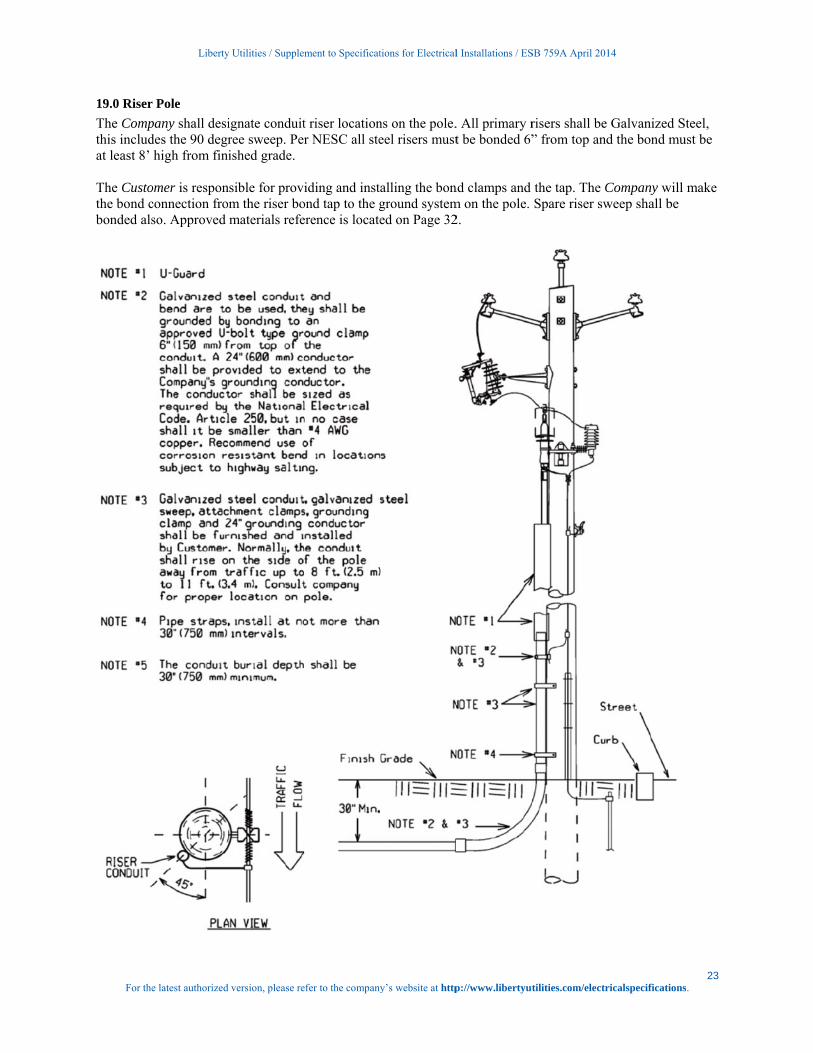
19.0 Riser
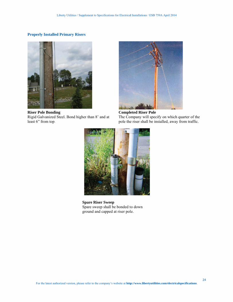
The Compthis includat least 8’ The Custothe bond cbonded als
Liberty
e latest authorized
r Pole
pany shall desides the 90 degrhigh from fin
omer is responconnection froso. Approved
y Utilities / Supple
d version, please re
ignate conduitree sweep. Perished grade.
nsible for provm the riser bomaterials refe
ment to Specificat
efer to the company
t riser locationr NESC all ste
iding and instond tap to the gerence is locate
tions for Electrical
y’s website at http
ns on the pole.eel risers must
alling the bonground systemed on Page 32
l Installations / ES
p://www.libertyut
. All primary rt be bonded 6”
nd clamps and m on the pole. 2.
SB 759A April 201
tilities.com/electr
risers shall be ” from top and
the tap. The CSpare riser sw
14
ricalspecifications
Galvanized Sd the bond mu
Company will weep shall be
23 s.
Steel, ust be
make
For the
Properly
Riser PoleRigid Galvleast 6” fro
Liberty
e latest authorized
Installed Prim
e Bonding vanized Steel.om top.
y Utilities / Supple
d version, please re
mary Risers
Bond higher
SpaSpagro
ment to Specificat
efer to the company
than 8’ and at
are Riser Sweare sweep shalound and capp
tions for Electrical
y’s website at http
t CompleThe Compole the
eep ll be bonded toed at riser pol
l Installations / ES
p://www.libertyut
eted Riser Pompany will spe riser shall be
o down le.
SB 759A April 201
tilities.com/electr
ole pecify on whice installed, aw
14
ricalspecifications
ch quarter of thay from traffic
24 s.
he c.
For the
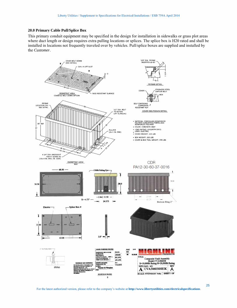
20.0 Prima
This primawhere ducinstalled inthe Custom
Liberty
e latest authorized
ary Cable Pul
ary conduit eqct length or den locations nomer.
y Utilities / Supple
d version, please re
ll/Splice Box
quipment may sign requires e
ot frequently tr
ment to Specificat
efer to the company
be specified iextra pulling lraveled over b
tions for Electrical
y’s website at http
in the design flocations or spy vehicles. Pu
l Installations / ES
p://www.libertyut
for installationplices. The splull/splice boxe
SB 759A April 201
tilities.com/electr
n in sidewalks lice box is H20es are supplied
14
ricalspecifications
or grass plot a0 rated and shd and installed
25 s.
areas hall be d by
For the
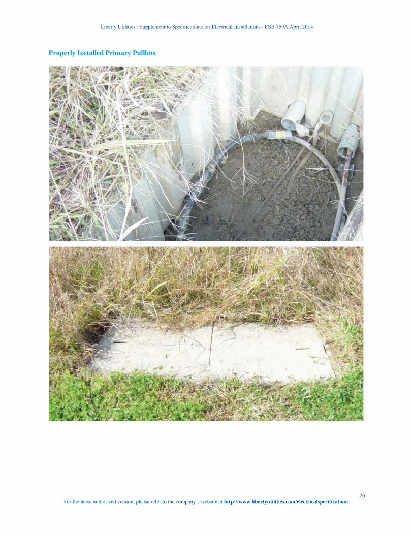
Properly
Liberty
e latest authorized
Installed Prim
y Utilities / Supple
d version, please re
mary Pullbox
ment to Specificat
efer to the company
x
tions for Electrical
y’s website at http
l Installations / ES
p://www.libertyut
SB 759A April 201
tilities.com/electr
14
ricalspecifications26
s.
Liberty Utilities / Supplement to Specifications for Electrical Installations / ESB 759A April 2014
27 For the latest authorized version, please refer to the company’s website at http://www.libertyutilities.com/electricalspecifications.
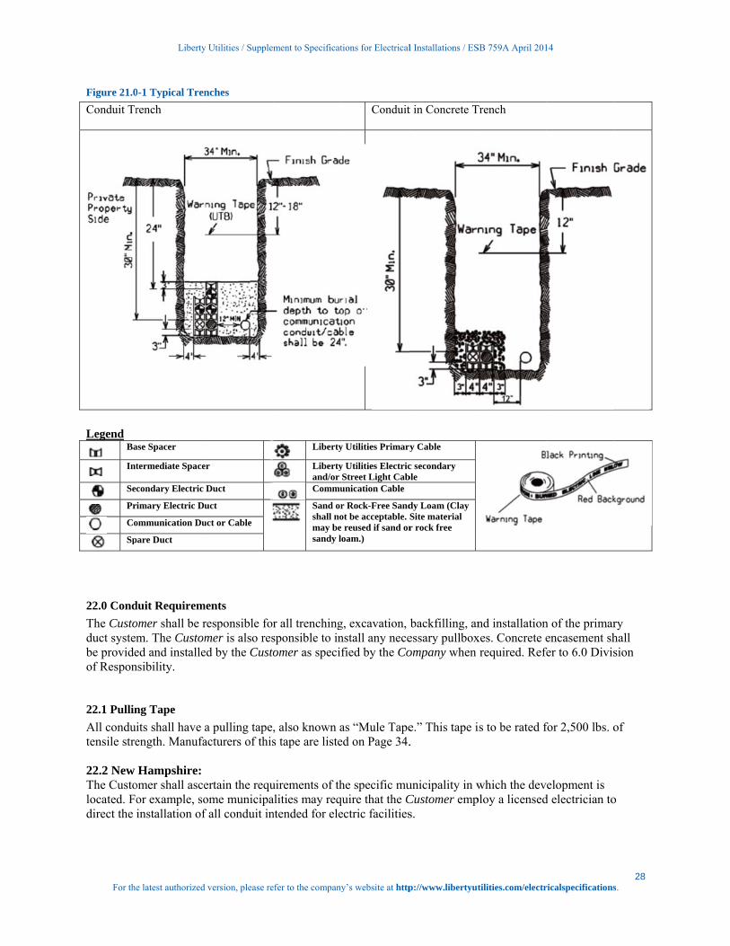
21.0 Trench Requirements
Final grades shall be established; the surface rough graded within 6” of finished grade, and roadway and property boundaries shall be staked or marked by the Customer before any trenching is started. The Customer shall adhere to the construction plan and specifications regarding trench locations, trench depth, and concrete encasement. Any deviation shall be subject to approval by the Company. The Company shall be notified in advance of the backfilling of any electric facility. The Company reserves the right to require re-excavation of the conduits and foundations if the Customer fails to have inspection done or backfills before inspection. For special circumstances that call for concrete encasement, such as crossing a culvert or stream, trenches shall not be backfilled until concrete has set (for at least two hours) and after approval by authorized Company personnel. All backfill shall be sand or gravel containing stones less than 1" in any dimension. Backfilling shall not take place over any open-ended (unplugged) conduits. Company approved red “Warning” tape shall be installed directly above the Company’s cable eight to 12 inches below finished grade. Laying the warning tape directly on the cable, concrete or conduit is not acceptable. Certain installations in the public way may require flowable fill instead in place of normal backfill. 21.1 Trench Depth Concrete Encased Conduit Burial depths for electrical conduit shall be maintained not less than 30" from the top of the concrete encasement to grade during all phases of construction. The trench bottom shall be solid, undisturbed earth. Earth showing signs of peat, cinders, rubble, or any conditions not suitable for a stable foundation shall be reported to the Company for recommendation. Small pockets of unsuitable soil shall be replaced with compacted gravel (maximum 2" stone). At riser pole, end concrete encasement just before riser sweep.
For the
Figure 21.0
Conduit Tr
Legend
Ba
Int
Sec
Pr
Co
Sp
22.0 Cond
The Custoduct systembe provideof Respon
22.1 Pullin
All conduitensile stre 22.2 New The Custolocated. Fodirect the
Liberty
e latest authorized
0-1 Typical Tren
rench
ase Spacer
termediate Space
condary Electric
imary Electric Du
ommunication Du
pare Duct
duit Requirem
omer shall be rm. The Customed and installensibility.
ng Tape
its shall have ength. Manufa
Hampshire: omer shall asceor example, soinstallation of
y Utilities / Supple
d version, please re
nches
er
Duct
uct
uct or Cable
ments
responsible former is also res
ed by the Custo
a pulling tapeacturers of this
ertain the requome municipaf all conduit in
ment to Specificat
efer to the company
Liberty
Libertyand/or Commu
Sand orshall nomay besandy l
r all trenchingsponsible to inomer as specif
, also known as tape are liste
uirements of thalities may reqntended for ele
tions for Electrical
y’s website at http
Conduit
y Utilities Primary
y Utilities ElectricStreet Light Cabunication Cable
r Rock-Free Sandot be acceptable. S reused if sand oroam.)
g, excavation, nstall any necefied by the Co
as “Mule Tapeed on Page 34.
he specific muquire that the Cectric facilities
l Installations / ES
p://www.libertyut
t in Concrete T
y Cable
c secondary ble
dy Loam (Clay Site material r rock free
backfilling, anessary pullboxompany when
e.” This tape i.
unicipality in wCustomer emps.
SB 759A April 201
tilities.com/electr
Trench
nd installationxes. Concrete erequired. Refe
is to be rated f
which the devploy a licensed
14
ricalspecifications
n of the primarencasement sh
fer to 6.0 Divis
for 2,500 lbs. o
velopment is d electrician to
28 s.
ry hall sion
of
o
Liberty Utilities / Supplement to Specifications for Electrical Installations / ESB 759A April 2014
29 For the latest authorized version, please refer to the company’s website at http://www.libertyutilities.com/electricalspecifications.
Temporary mechanical protection over buried conduit and encasements is recommended to prevent crushing or damage during construction, and is the Customer’s responsibility. All road crossings shall, when practical, be perpendicular to the sidelines of the road. The minimum conduit size shall be 4” for three phase and 3” for single phase cable installations. All sweeps at foundations and risers shall have a minimum radius of 36 inches. The riser sweep shall be galvanized steel. The Customer shall install conduit plugs in all unused conduits and pulling tape. At the riser pole, the galvanized rigid steel sweeps and the PVC/steel adaptors shall not be concrete encased. The Customer shall be responsible to install rigid galvanized steel straight conduit up the pole high enough to meet NESC code referenced on the riser pole requirements on Page 23, including conduit ground straps, up the riser pole (unless directed otherwise by the Company). The Company will specify on which quarter of the pole the riser shall be installed, usually away from oncoming traffic. Except as noted on construction prints, curves and bends in conduit shall be gradual, and the radius of curvature shall not be less than 40 feet. All curves shall be formed with five-degree couplings. The minimum length between single, five-degree couplings is 42". Conduit grade shall be such as to cause all ducts to drain toward one or both equipment foundations or pullboxes. Minimum pitch shall be three inches per 100 feet. The Customer shall insure that clearances are met and maintained, and that they are inspected by the Company. Unless local jurisdictions require greater clearances, the minimum clearances shall be as follows: 22.3 Communication Systems – Company conduit shall not be directly above or below communication conduit, except when crossing below communication conduit at approximately right angles. Company conduit and communication conduit shall be separated by a minimum of 3" of concrete encasement. 22.4 Non-Company Water, Gas and Sewer – Company conduit shall not be directly above or below any of these foreign utilities, except when crossing above these utilities at approximately right angles. Where the paths of these foreign utilities cross under Company conduits at approximately right angles, the minimum separation is 12". A minimum separation of 24" shall be maintained between parallel placement of any of these utilities and electrical conduit. A six-inch clearance shall be between conduit envelopes and major subsurface pipes (e.g. drainage pipes). The Customer shall rod and mandrel all primary conduits to insure their integrity before the Company shall attempt to pull any primary cable. The Customer shall furnish and install an approved synthetic, 2,500 pound test tape in each primary conduit run including risers. Pulling tape installation and rodding the duct shall be witnessed by the Company. Company-owned duct shall not share a concrete encasement with foreign utilities (e.g. do not place communication or private electrical duct in the same concrete encasement as Company duct). At those locations where manholes or above ground switchgear are required, additional specifications will be provided by the Company.
23.0 Metering
Refer to the Company’s Specification for Electrical Installations book for the type of installation. Division of work and material will be performed with the approval and authorization of the Company’s Metering Services department. In most instances, the Company will furnish, install, own, maintain and connect all meters required for billing purposes at the delivery voltage on the customer’s side of the service point.

Liberty Utilities / Supplement to Specifications for Electrical Installations / ESB 759A April 2014
30 For the latest authorized version, please refer to the company’s website at http://www.libertyutilities.com/electricalspecifications.
24.0 Easement Applications Form
LIBERTY UTILITIES EASEMENT APPLICATION FORM
FOR LIBERTY UTILITIES’ USE ONLY Application for Easements (check one): ❒ OH (jointly owned or solely owned)
❒ Padmount transformer only ❒ UG ❒ URD
❒ Electric ❒ Gas
Work Request Number ______________________________________________________________________________ Utility Engineer’s Name: ___________________________________________ Telephone Number: _________________ Please complete ALL of the sections below so that we may prepare an easement for your signature. Do not leave any sections unanswered. If a section does not apply to you simply put “n/a” on that line. Incorrect or incomplete information will delay service installation. Property Owner(s): __________________________________________________________________________________ Property Owner Mailing Address Property Address of Easement
(if different from mailing address)
Address: Address: City:
City:
State & County
State & County
Zip
Zip
Customer Contact Person:
Daytime Phone(s):
Re: Subdivision Title:
1. Provide us with a RECORDED copy of the present owner’s deed, Book________ Page________
a) If multiple deeds make up the whole parcel, please include all deeds.
b) If the Property Owner is a b1) CORPORATION, b2) TRUST, b3) PARTNERSHIP, or b4) LIMITED
LIABILITY COMPANY, provide the following which is applicable: b1) President Name: _____________________Treasurer Name: _____________________________ See Footnote1 Below
Or Vice President:________________________Asst. Treasurer:_______________________________
1 If neither “Name Combinations” is available, the person(s) signing the easement must have a Corporate vote authorizing them to sign on behalf of the Corporation.

For the
2. a)
b)
3. Is
If
a) N
b) A
c) D D
Additional C
Please
Liberty
e latest authorized
b2) Tru Name o b3) Par b4) LLC
) Provide us wit
Plan Book:___
If there is no re
Assessor’s Map
s your property
f “YES”, please
Name of Bank/C
Address of mortg
Date and recordin
Date:_________
Comments:
contact your A
y Utilities / Supple
d version, please re
ust: No. Of Trus
of Trust:______
rtnership: Numb
C: Authorizatio
th an approved:
_____________
ecorded subdivi
p:___________
mortgaged (circ
complete this s
Company/Person
gage holder(s):
ng information
County Record
Account Manage
ment to Specificat
efer to the company
stees:_________
_____________
ber of Partners:_
on to Sign, Nam
“Definitive Su
_______ Plan:__
ision plan pleas
_______Block:_
cle one)?
section:
n holding mortg
____________
of mortgage(s)
ded:__________
er or Service Ad
tions for Electrical
y’s website at http
_____________
_____________
_____________
me(s):_________
ubdivision Plan”
_____________
e include the fo
_____________
YES
gage(s):_______
______________
: ___________
________ Book
dministrator if y
l Installations / ES
p://www.libertyut
___Name(s): __
_____________
__Name(s):___
_____________
”
________ Dated
ollowing inform
_________ and
NO
_____________
_____________
_____________
k:___________
you have any q
SB 759A April 201
tilities.com/electr
_____________
_____________
_____________
_____________
d:____________
mation:
Lot:_________
_____________
_____________
_____________
____ Page:____
questions regard
14
ricalspecifications
_____________
_____________
_____________
_____________
___________
____________
_______
_________
_________
__________
ding this form.
31 s.
_____
______
______
_____
Liberty Utilities / Supplement to Specifications for Electrical Installations / ESB 759A April 2014
32 For the latest authorized version, please refer to the company’s website at http://www.libertyutilities.com/electricalspecifications.
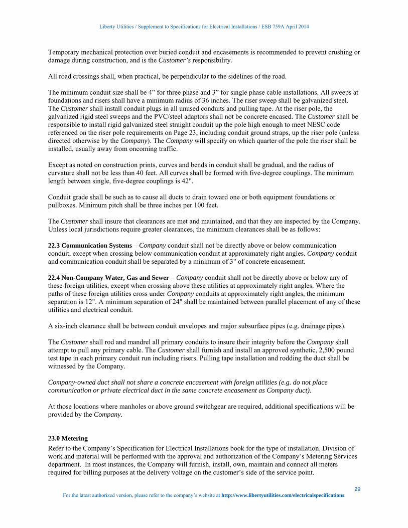
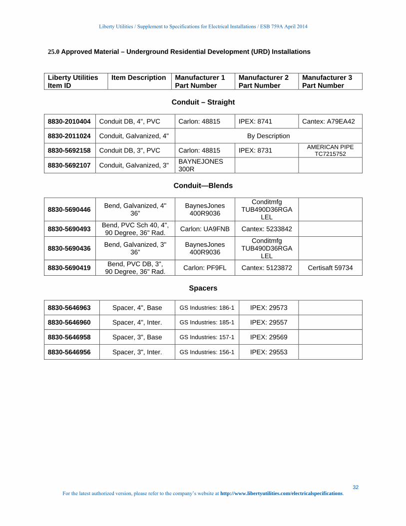
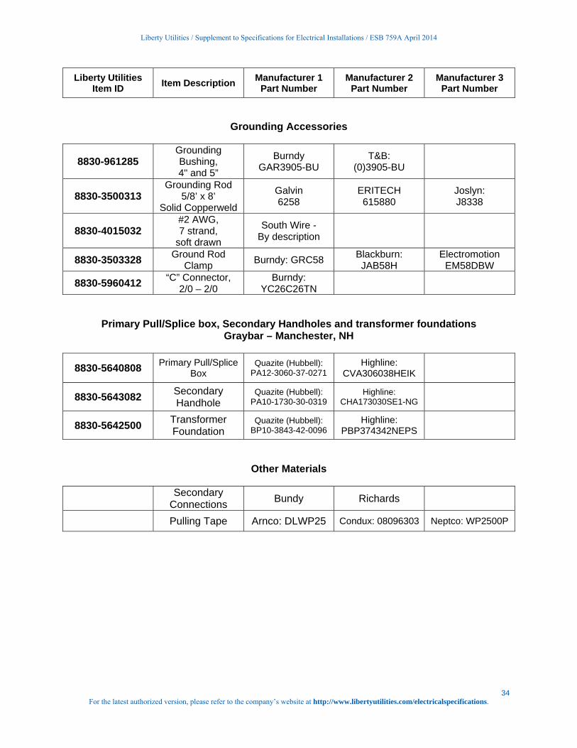
25.0 Approved Material – Underground Residential Development (URD) Installations
Liberty Utilities Item ID
Item Description Manufacturer 1 Part Number
Manufacturer 2 Part Number
Manufacturer 3 Part Number
Conduit – Straight
8830-2010404 Conduit DB, 4", PVC Carlon: 48815 IPEX: 8741 Cantex: A79EA42
8830-2011024 Conduit, Galvanized, 4" By Description
8830-5692158 Conduit DB, 3", PVC Carlon: 48815 IPEX: 8731 AMERICAN PIPE TC7215752
8830-5692107 Conduit, Galvanized, 3" BAYNEJONES 300R
Conduit—Blends
8830-5690446 Bend, Galvanized, 4"
36” BaynesJones
400R9036
Conditmfg TUB490D36RGA
LEL
8830-5690493 Bend, PVC Sch 40, 4", 90 Degree, 36" Rad.
Carlon: UA9FNB Cantex: 5233842
8830-5690436 Bend, Galvanized, 3"
36” BaynesJones
400R9036
Conditmfg TUB490D36RGA
LEL
8830-5690419 Bend, PVC DB, 3",
90 Degree, 36" Rad. Carlon: PF9FL Cantex: 5123872 Certisaft 59734
Spacers
8830-5646963 Spacer, 4", Base GS Industries: 186-1 IPEX: 29573
8830-5646960 Spacer, 4", Inter. GS Industries: 185-1 IPEX: 29557
8830-5646958 Spacer, 3", Base GS Industries: 157-1 IPEX: 29569
8830-5646956 Spacer, 3", Inter. GS Industries: 156-1 IPEX: 29553
Liberty Utilities / Supplement to Specifications for Electrical Installations / ESB 759A April 2014
33 For the latest authorized version, please refer to the company’s website at http://www.libertyutilities.com/electricalspecifications.
Liberty Utilities Item ID
Item Description Manufacturer 1
Part Number Manufacturer 2
Part Number Manufacturer 3
Part Number
Conduit Accessories
8830-5641210 Riser Strap, 4” Electrical Materials:
50-4 USHD
BaynesJones MINRLAC HD-296
8830-5641205 Riser Strap, 3” Electrical Materials:
50-3 USHD
BaynesJones MINRLAC HD-294
8830-7011830 Lag Screw, ¼” x 2” Elect. Materials:
106 or 106M Joslyn J26486.1
PLH LSNW-142
8830-3503074 Pipe Grd. Connector, 4” and 5”
T & B: (0)3905-BU
Burndy GAR3905-BU
8830-3503075 Pipe Grd. Connector, 2.5” and 3.5” T & B: (O)3904-BU
Burndy: GAR3904-BU
8830-2010424 Duct Plug, 4” DB Carlon: P258NT BGAR3905-BU
8830-5645682 Duct Plug, 3” DB CSNTEX: 5315260
CARLON: P258L
CERTIFSAFT: 59653
8830-2011254 Duct Plug
Galvanized 4” Crousehind PLG105
8830-9201659 Duct Plug
Galvanized 3”
8830-2010434 Adapter, Female,
PVC-Steel, 4” Carlon: E942N Cantex: 5140052 Scepter FA55
8830-2010433 Adapter, Female,
PVC-Steel, 3” Carlon: E942N
OZGEDNEY: PLG-300C
8830-5693359 Coupling, 5 Degree, Bell-Spigot, 4” Carlon: E244N Cantex: 6151452 Certisaft 59544
8830-5693356 Coupling, 5 Degree, Bell-Spigot, 3” Cantex: 6151450 Carlon: E244L
8830-2010444 Coupling, 5 Degree, Bell-Bell, 4” Ameripipe: FT518 Carlon E2440NF
Scepter 7604360040
8830-5100696 Coupling, 5 Degree, Bell-Bell, 3”0 Ameripipe: NS141 Carlon: 6151458
8830-2010454 Straight Coupling, 4”, EB/DB Carlon: E240N Cantex: 6151450
8830-2010453 Straight Coupling, 3”, EB/DB Cantex: 6151450 Carlon: E2544L
Liberty Utilities / Supplement to Specifications for Electrical Installations / ESB 759A April 2014
34 For the latest authorized version, please refer to the company’s website at http://www.libertyutilities.com/electricalspecifications.
Liberty Utilities Item ID
Item Description Manufacturer 1
Part Number Manufacturer 2
Part Number Manufacturer 3
Part Number
Grounding Accessories
8830-961285 Grounding Bushing, 4" and 5”
Burndy GAR3905-BU
T&B: (0)3905-BU
8830-3500313 Grounding Rod
5/8’ x 8’ Solid Copperweld
Galvin 6258
ERITECH 615880
Joslyn: J8338
8830-4015032 #2 AWG, 7 strand,
soft drawn
South Wire - By description
8830-3503328 Ground Rod
Clamp Burndy: GRC58
Blackburn: JAB58H
Electromotion EM58DBW
8830-5960412 “C” Connector,
2/0 – 2/0 Burndy:
YC26C26TN
Primary Pull/Splice box, Secondary Handholes and transformer foundations Graybar – Manchester, NH
8830-5640808 Primary Pull/Splice
Box Quazite (Hubbell):
PA12-3060-37-0271 Highline:
CVA306038HEIK
8830-5643082 Secondary Handhole
Quazite (Hubbell): PA10-1730-30-0319
Highline: CHA173030SE1-NG
8830-5642500 Transformer Foundation
Quazite (Hubbell): BP10-3843-42-0096
Highline: PBP374342NEPS
Other Materials
Secondary Connections
Bundy Richards
Pulling Tape Arnco: DLWP25 Condux: 08096303 Neptco: WP2500P
Liberty Utilities / Supplement to Specifications for Electrical Installations / ESB 759A April 2014
35 For the latest authorized version, please refer to the company’s website at http://www.libertyutilities.com/electricalspecifications.
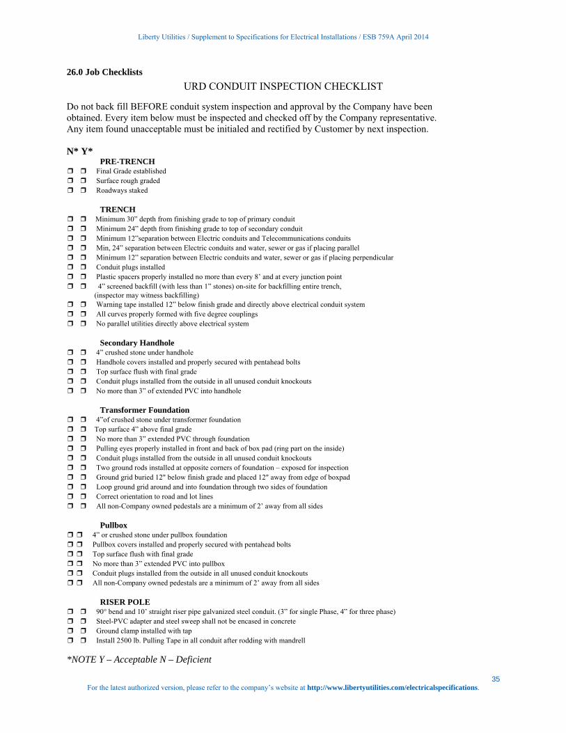
26.0 Job Checklists
URD CONDUIT INSPECTION CHECKLIST
Do not back fill BEFORE conduit system inspection and approval by the Company have been obtained. Every item below must be inspected and checked off by the Company representative. Any item found unacceptable must be initialed and rectified by Customer by next inspection. N* Y*
PRE-TRENCH ❒ ❒ Final Grade established ❒ ❒ Surface rough graded ❒ ❒ Roadways staked
TRENCH ❒ ❒ Minimum 30” depth from finishing grade to top of primary conduit ❒ ❒ Minimum 24” depth from finishing grade to top of secondary conduit ❒ ❒ Minimum 12”separation between Electric conduits and Telecommunications conduits ❒ ❒ Min, 24” separation between Electric conduits and water, sewer or gas if placing parallel ❒ ❒ Minimum 12” separation between Electric conduits and water, sewer or gas if placing perpendicular ❒ ❒ Conduit plugs installed ❒ ❒ Plastic spacers properly installed no more than every 8’ and at every junction point ❒ ❒ 4” screened backfill (with less than 1” stones) on-site for backfilling entire trench, (inspector may witness backfilling) ❒ ❒ Warning tape installed 12” below finish grade and directly above electrical conduit system ❒ ❒ All curves properly formed with five degree couplings ❒ ❒ No parallel utilities directly above electrical system
Secondary Handhole ❒ ❒ 4” crushed stone under handhole ❒ ❒ Handhole covers installed and properly secured with pentahead bolts ❒ ❒ Top surface flush with final grade ❒ ❒ Conduit plugs installed from the outside in all unused conduit knockouts ❒ ❒ No more than 3” of extended PVC into handhole
Transformer Foundation ❒ ❒ 4”of crushed stone under transformer foundation ❒ ❒ Top surface 4” above final grade ❒ ❒ No more than 3” extended PVC through foundation ❒ ❒ Pulling eyes properly installed in front and back of box pad (ring part on the inside) ❒ ❒ Conduit plugs installed from the outside in all unused conduit knockouts ❒ ❒ Two ground rods installed at opposite corners of foundation – exposed for inspection ❒ ❒ Ground grid buried 12" below finish grade and placed 12" away from edge of boxpad ❒ ❒ Loop ground grid around and into foundation through two sides of foundation ❒ ❒ Correct orientation to road and lot lines ❒ ❒ All non-Company owned pedestals are a minimum of 2’ away from all sides
Pullbox ❒ ❒ 4” or crushed stone under pullbox foundation ❒ ❒ Pullbox covers installed and properly secured with pentahead bolts ❒ ❒ Top surface flush with final grade ❒ ❒ No more than 3” extended PVC into pullbox ❒ ❒ Conduit plugs installed from the outside in all unused conduit knockouts ❒ ❒ All non-Company owned pedestals are a minimum of 2’ away from all sides
RISER POLE ❒ ❒ 90° bend and 10’ straight riser pipe galvanized steel conduit. (3” for single Phase, 4” for three phase) ❒ ❒ Steel-PVC adapter and steel sweep shall not be encased in concrete ❒ ❒ Ground clamp installed with tap ❒ ❒ Install 2500 lb. Pulling Tape in all conduit after rodding with mandrell
*NOTE Y – Acceptable N – Deficient

Liberty Utilities / Supplement to Specifications for Electrical Installations / ESB 759A April 2014
36 For the latest authorized version, please refer to the company’s website at http://www.libertyutilities.com/electricalspecifications.
27.0 Revision History
Date Rev # Description Author/Lead Person07/03/12 0 Initial version of document Robert J. Johnson
04/01/14 1.0 Update to reflect new Liberty Utilities Policy 2 Line Extension Policy for Residential Developments (URD)
Robert J. Johnson

Liberty Utilities is an independent water, natural gas, and electric company providing local
utility management, service and support to small and mid- sized communities across the
United States. Serving over 470,000 customers in ten states, Liberty Utilities is committed
to local decision making that directly meets the needs of its customers. This means
providing walk in customer service centers, creating jobs, and providing responsive and
reliable service. As a company, Liberty Utilities promotes local conservation and energy
efficiency initiatives and programs for businesses and residential customers, including the
low-income sector. The company measures its performance on customer experience, public
and workplace safety, and service reliability. Liberty Utilities currently operates in Arizona,
Arkansas, California, Illinois, Iowa, Georgia, Massachusetts, Missouri, New Hampshire, and Texas.
For more information, please visit www.LibertyUtilities.com.
Liberty Utilities
15 Buttrick Rd
Londonderry, NH 03053
1-800-375-7413
www.libertyutilities.com


