48
Installation and Operation Manual X-DPT-PROFIBUS-4800-eng Part Number: 541B135AAG February, 2010 Supplemental Manual for Brooks ® 4800 Series PROFIBUS ® MFCs/MFMs
Installation and Operation Manual X-DPT-PROFIBUS-4800-eng Part Number: 541B135AAG February, 2010
Supplemental Manual for Brooks® 4800 Series PROFIBUS® MFCs/MFMs
Installation and Operation Manual X-DPT-PROFIBUS-4800-eng Part Number: 541B135AAG February, 2010
Brooks 4800 PROFIBUS MFCs/MFMs
Essential Instructions Read this page before proceeding!
Brooks Instrument designs, manufactures and tests its products to meet many national and international standards. Because these instruments are sophisticated technical products, you must properly install, use and maintain them to ensure they continue to operate within their normal specifications. The following instructions must be adhered to and integrated into your safety program when installing, using and maintaining Brooks Products.
• Read all instructions prior to installing, operating and servicing the product. If this instruction manual is not the correct manual, please see back cover for local sales office contact information. Save this instruction manual for future reference.
• If you do not understand any of the instructions, contact your Brooks Instrument representative for clarification.
• Follow all warnings, cautions and instructions marked on and supplied with the product.
• Inform and educate your personnel in the proper installation, operation and maintenance of the product.
• Install your equipment as specified in the installation instructions of the appropriate instruction manual and per applicable local and national codes. Connect all products to the proper electrical and pressure sources.
• To ensure proper performance, use qualified personnel to install, operate, update, program and maintain the product.
• When replacement parts are required, ensure that qualified people use replacement parts specified by Brooks Instrument.
• Unauthorized parts and procedures can affect the product's performance and place the safe operation of your process at risk. Look-alike substitutions may result in fire, electrical hazards or improper operation.
• Ensure that all equipment doors are closed and protective covers are in place, except when maintenance is being performed by qualified persons, to prevent electrical shock and personal injury.
ESD (Electrostatic Discharge)
This instrument contains electronic components that are susceptible to damage by electricity. Proper handling procedures must be observed during the removal, installation, or other handling of internal circuit boards or devices.
Handling Procedure:
1. Power to the unit must be removed.
2. Personnel must be grounded, via a wrist strap or other safe, suitable means before any printed circuit card or other internal device is installed, removed or adjusted.
3. Printed circuit cards must be transported in a conductive container. Boards must not be removed from protective enclosure until immediately before installation. Removed boards must immediately be placed in protective container for transport, storage or return to factory.
Comments:
This instrument is not unique in its content of ESD (electrostatic discharge) sensitive components. Most modern electronic designs contain components that utilize metal oxide technology (NMOS, SMOS, etc.). Experience has proven that even small amounts of static electricity can damage or destroy these devices. Damaged components, even though they appear to function properly, exhibit early failure.

Installation and Operation Manual X-DPT-PROFIBUS-4800-eng Part Number: 541B135AAG February, 2010
iii
Brooks 4800 PROFIBUS MFCs/MFMs
Dear Customer, We appreciate this opportunity to service your flow measurement and control requirements with a Brooks Instrument device. Every day, flow customers all over the world turn to Brooks Instrument for solutions to their gas and liquid low-flow applications. Brooks provides an array of flow measurement and control products for various industries from biopharmaceuticals, oil and gas, fuel cell research and chemicals, to medical devices, analytical instrumentation, semiconductor manufacturing, and more. The Brooks product you have just received is of the highest quality available, offering superior performance, reliability and value to the user. It is designed with the ever changing process conditions, accuracy requirements and hostile process environments in mind to provide you with a lifetime of dependable service. We recommend that you read this manual in its entirety. Should you require any additional information concerning Brooks products and services, please contact your local Brooks Sales and Service Office listed on the back cover of this manual or visit www.BrooksInstrument.com Yours sincerely, Brooks Instrument

Installation and Operation Manual X-DPT-PROFIBUS-4800-eng Part Number: 541B135AAG February, 2010
iv
Brooks 4800 PROFIBUS MFCs/MFMs
THIS PAGE WAS INTENTIONALLY
LEFT BLANK
Installation and Operation Manual X-DPT-PROFIBUS-4800-eng Part Number: 541B135AAG February, 2010
v
Contents
Brooks 4800 PROFIBUS MFCs/MFMs
Table of Contents
1. Introduction..............................................................................................................................................1
1.1. How to Use This Manual ...........................................................................................................1 1.2. Description.................................................................................................................................2 1.3. Specifications ............................................................................................................................2 1.4. Definition of Terms ....................................................................................................................3
2. Receipt & Storage....................................................................................................................................5
2.1. General ......................................................................................................................................5 2.2. Receipt of Equipment ................................................................................................................5 2.3. Recommended Storage Practice ..............................................................................................6 2.4. Return of Equipment..................................................................................................................6 2.5. Transit Precautions....................................................................................................................7 2.6. Removal from Storage...............................................................................................................7
3. Background & Numbering ......................................................................................................................9
3.1. Background & Assumptions ......................................................................................................9 3.2. Numbers ....................................................................................................................................9
4. Installation..............................................................................................................................................11
4.1. Supported Baud rates..............................................................................................................11 4.2. Address Selection....................................................................................................................11 4.3. Bus and Device LEDs..............................................................................................................12 4.4. Profibus Bus signals ................................................................................................................13 4.5. Power Supply...........................................................................................................................13
5. Slave Configuration...............................................................................................................................15
5.1. Introduction..............................................................................................................................15 5.2. Parameterization of the Slave (48xx Series MFC/MFM).........................................................15 5.3. Configuration of the Slave (48xx Series MFC) ........................................................................18 5.4. Configuration of the Slave (48xx Series MFM)........................................................................20 5.5. Device Diagnostics ..................................................................................................................21
6. DPV0 Cyclic Data Exchange.................................................................................................................23
7. DPV1 Acyclic Data Communication.....................................................................................................25
7.1. Device Block Model .................................................................................................................25 7.2. Slot and Index (attribute) Mapping ..........................................................................................26 7.3. Identification & Maintenance Function (I&M0)........................................................................27
Installation and Operation Manual X-DPT-PROFIBUS-4800-eng Part Number: 541B135AAG February, 2010
vi
Contents
Brooks 4800 PROFIBUS MFCs/MFMs 7.4. TMF Device Physical Block (Slot 0; PB_1) .............................................................................29
7.4.1. Note: Attribute 5.......................................................................................................29 7.5. TMF Sensor Transducer Block (Slot 4; TB_1) ........................................................................30
7.5.1. Note: Attribute 0.......................................................................................................31 7.5.2. Note: Attribute 2.......................................................................................................31 7.5.3. Note: Attribute 3.......................................................................................................31 7.5.4. Note: Attribute 9.......................................................................................................32
7.6. Analog Sensor Function Block (Slot 1; FB_1) .........................................................................32 7.7. Controller Function Block (Slot 2; FB_2) (Not supported by MFM).........................................33
7.7.1. Note: Attribute 0.......................................................................................................34 7.7.2. Note: Attribute 4.......................................................................................................34
7.8. Actuator Function Block (Slot 3; FB_3) (Not supported by MFM)...........................................34 7.8.1. Note: Attribute 0.......................................................................................................35 7.8.2. Note: Attribute 6.......................................................................................................35 7.8.3. Note: Attribute 7.......................................................................................................36
7.9. Actuator Transducer Block (Slot 5; TB_2) (Not supported by MFM).......................................36 7.9.1. Note: Attribute 1.......................................................................................................36
8. Appendices ............................................................................................................................................37
8.1. Appendix A Data type definitions.............................................................................................37 8.2. Appendix B Data Units ............................................................................................................38
Installation and Operation Manual X-DPT-PROFIBUS-4800-eng Part Number: 541B135AAG February, 2010
vii
Contents
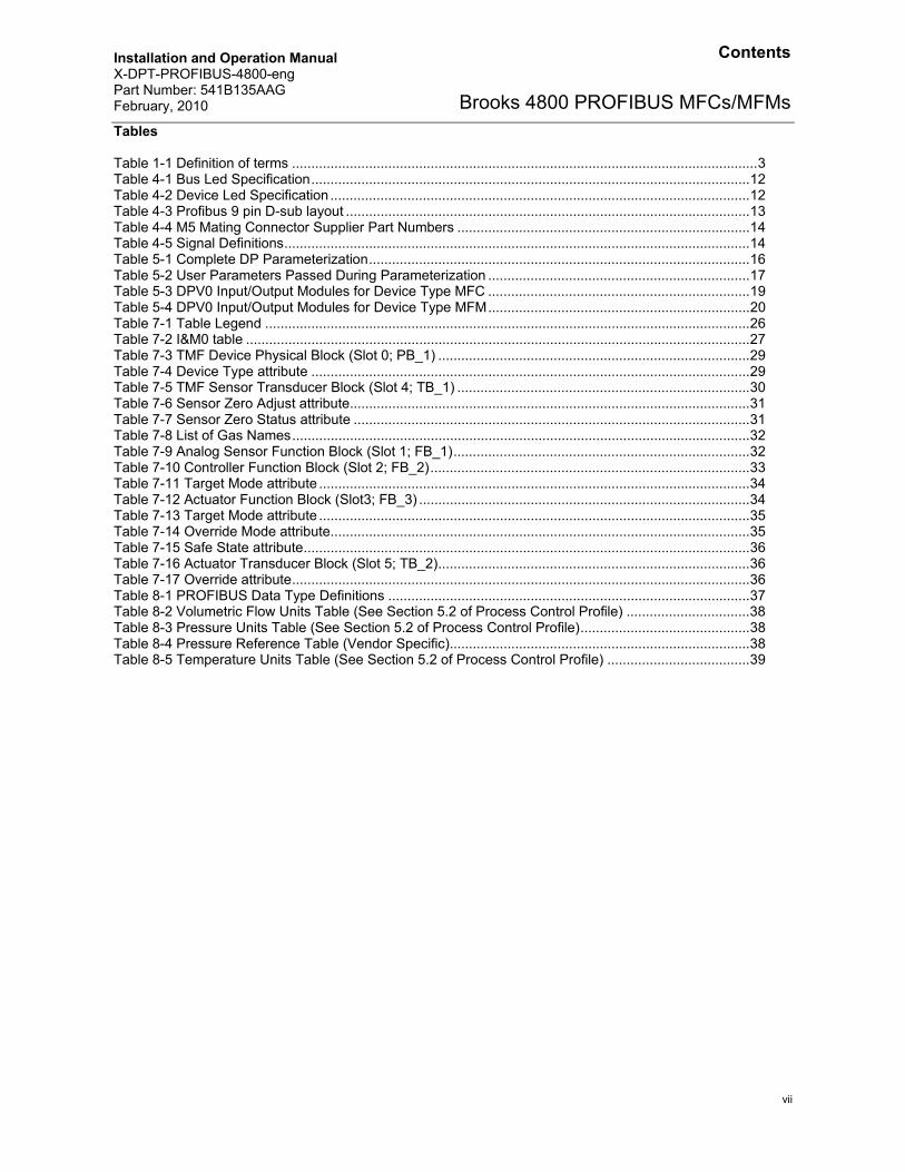
Brooks 4800 PROFIBUS MFCs/MFMsTables Table 1-1 Definition of terms .........................................................................................................................3 Table 4-1 Bus Led Specification..................................................................................................................12 Table 4-2 Device Led Specification .............................................................................................................12 Table 4-3 Profibus 9 pin D-sub layout .........................................................................................................13 Table 4-4 M5 Mating Connector Supplier Part Numbers ............................................................................14 Table 4-5 Signal Definitions.........................................................................................................................14 Table 5-1 Complete DP Parameterization...................................................................................................16 Table 5-2 User Parameters Passed During Parameterization ....................................................................17 Table 5-3 DPV0 Input/Output Modules for Device Type MFC ....................................................................19 Table 5-4 DPV0 Input/Output Modules for Device Type MFM....................................................................20 Table 7-1 Table Legend ..............................................................................................................................26 Table 7-2 I&M0 table ...................................................................................................................................27 Table 7-3 TMF Device Physical Block (Slot 0; PB_1) .................................................................................29 Table 7-4 Device Type attribute ..................................................................................................................29 Table 7-5 TMF Sensor Transducer Block (Slot 4; TB_1) ............................................................................30 Table 7-6 Sensor Zero Adjust attribute........................................................................................................31 Table 7-7 Sensor Zero Status attribute .......................................................................................................31 Table 7-8 List of Gas Names.......................................................................................................................32 Table 7-9 Analog Sensor Function Block (Slot 1; FB_1).............................................................................32 Table 7-10 Controller Function Block (Slot 2; FB_2)...................................................................................33 Table 7-11 Target Mode attribute ................................................................................................................34 Table 7-12 Actuator Function Block (Slot3; FB_3) ......................................................................................34 Table 7-13 Target Mode attribute ................................................................................................................35 Table 7-14 Override Mode attribute.............................................................................................................35 Table 7-15 Safe State attribute....................................................................................................................36 Table 7-16 Actuator Transducer Block (Slot 5; TB_2).................................................................................36 Table 7-17 Override attribute.......................................................................................................................36 Table 8-1 PROFIBUS Data Type Definitions ..............................................................................................37 Table 8-2 Volumetric Flow Units Table (See Section 5.2 of Process Control Profile) ................................38 Table 8-3 Pressure Units Table (See Section 5.2 of Process Control Profile)............................................38 Table 8-4 Pressure Reference Table (Vendor Specific)..............................................................................38 Table 8-5 Temperature Units Table (See Section 5.2 of Process Control Profile) .....................................39

Installation and Operation Manual X-DPT-PROFIBUS-4800-eng Part Number: 541B135AAG February, 2010
viii
Contents
Brooks 4800 PROFIBUS MFCs/MFMs Figures Figure 4-1 PROFIBUS Label on Cover .......................................................................................................12 Figure 4-2 Profibus 9 pin D-sub connector..................................................................................................13 Figure 4-3 M5 Mating Connector and Cable Specifications........................................................................14 Figure 5-1 Device Diagnostic Byte ..............................................................................................................21 Figure 7-1 Device Block Model....................................................................................................................25 Figure 7-2 Slot and Index definition.............................................................................................................26
Installation and Operation Manual X-DPT-PROFIBUS-4800-eng Part Number: 541B135AAG February, 2010
1
Section 1. Introduction
Brooks 4800 PROFIBUS MFCs/MFMs
1. Introduction
Many applications of Flow Controllers/Meters are moving to increasing use of automation. Automation comes in many forms: PLC’s (Programmable Logic Controllers such as the Siemens S7 300/4000), DCS’s (Distributed Control Systems, such as Emerson’s Digital V), and PC based solutions (National Instrument’s LabviewTM). Digital communications from these varied systems and the devices they measure and control are a very effective means of not only accomplishing more effective and rapid system integration, but also providing greatly improved system diagnostics and maintainability. PROFIBUS is an open, digital communication system with a wide range of applications, particularly in the fields of factory and process automation. Brooks Instrument has several of its devices available on this universal fieldbus technology and is a member of the PROFIBUS organization.
1.1. How to Use This Manual
This instruction manual along with the 4800 Series product manual (X-TMF-4800-MFC-eng) is intended to provide the user with all the information necessary to install, operate and maintain the Brooks 4800 Series PROFIBUS digital interface module. This manual is organized into the following sections:
Section 1 – Introduction Section 2 – Receipt & Storage of Equipment Section 3 – Background & Numbering Section 4 – Installation Section 5 – Slave Configuration Section 6 – DPV0 Cyclic Exchange Section 7 – DPV1 Acyclic Communication Section 8 – Appendices
Installation and Operation Manual X-DPT-PROFIBUS-4800-eng Part Number: 541B135AAG February, 2010
2
Section 1. Introduction
Brooks 4800 PROFIBUS MFCs/MFMs
1.2. Description
Many applications of Flow Controllers/Meters are moving to increasing use of automation. Automation comes in many forms: PLC’s (Programmable Logic Controllers such as the Siemens S7 300/4000), DCS’s (Distributed Control Systems, such as Emerson’s Digital V), and PC based solutions (National Instrument’s LabviewTM). Digital communications from these varied systems and the devices they measure and control are a very effective means of not only accomplishing more effective and rapid system integration, but also providing greatly improved system diagnostics and maintainability. PROFIBUS is an open, digital communication system with a wide range of applications, particularly in the fields of factory and process automation. Brooks Instrument has several of its devices available on this universal fieldbus technology and is a member of the PROFIBUS organization
1.3. Specifications
Electrical Connections
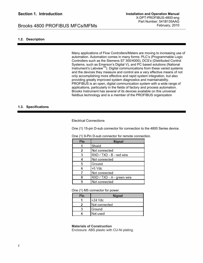
One (1) 15-pin D-sub connector for connection to the 4800 Series device. One (1) 9-Pin D-sub connector for remote connection.
One (1) M5 connector for power.
Materials of Construction Enclosure: ABS plastic with CU-Ni plating.
Installation and Operation Manual X-DPT-PROFIBUS-4800-eng Part Number: 541B135AAG February, 2010
3
Section 1. Introduction
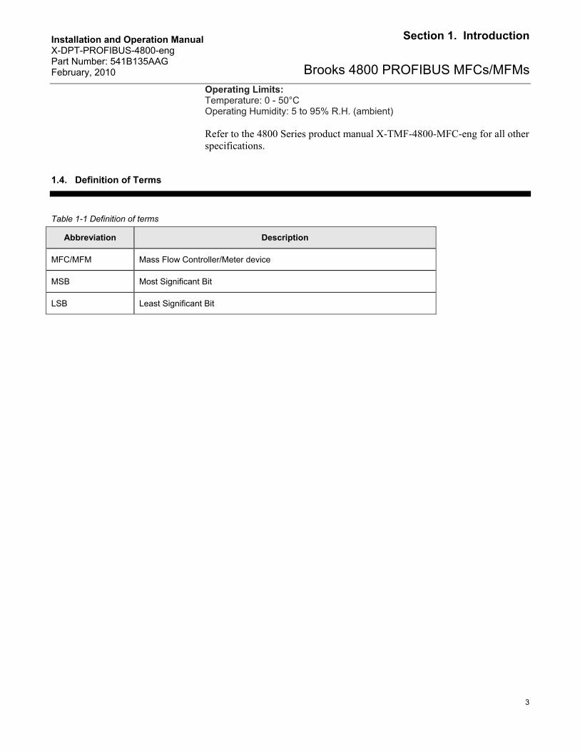
Brooks 4800 PROFIBUS MFCs/MFMsOperating Limits: Temperature: 0 - 50°C Operating Humidity: 5 to 95% R.H. (ambient) Refer to the 4800 Series product manual X-TMF-4800-MFC-eng for all other specifications.
1.4. Definition of Terms
Table 1-1 Definition of terms
Abbreviation Description
MFC/MFM Mass Flow Controller/Meter device
MSB Most Significant Bit
LSB Least Significant Bit

Installation and Operation Manual X-DPT-PROFIBUS-4800-eng Part Number: 541B135AAG February, 2010
4
Section 1. Introduction
Brooks 4800 PROFIBUS MFCs/MFMs
THIS PAGE WAS INTENTIONALLY
LEFT BLANK
Installation and Operation Manual X-DPT-PROFIBUS-4800-eng Part Number: 541B135AAG February, 2010
5
Section 2. Receipt & Storage
Brooks 4800 PROFIBUS MFCs/MFMs
2. Receipt & Storage
2.1. General
This section contains the procedures for the receipt and installation of the instrument. See Section 1 of this manual and the 4800 Series product manual (X-TMF-4800-MFC-eng) for dimensional and connection requirements. Do not attempt to start the system until the instrument has been permanently installed. It is important that the start-up procedures be followed in the exact sequence presented.
2.2. Receipt of Equipment
When the instrument is received, the outside packing case should be checked for damage incurred during shipment. If the packing case is damaged, the local carrier should be notified at once regarding his liability. A report should be submitted to your nearest Product Service Department.
Brooks Instrument 407 W. Vine Street P.O. Box 903 Hatfield, PA 19440 USA Toll Free (888) 554 FLOW (3569) Tel (215) 362 3700 Fax (215) 362 3745 E-mail: [email protected] www.BrooksInstrument.com Brooks Instrument Neonstraat 3 6718 WX Ede, Netherlands P.O. Box 428 6710 BK Ede, Netherlands Tel +31 (0) 318 549 300 Fax +31 (0) 318 549 309 E-mail: [email protected] Brooks Instrument 1-4-4 Kitasuna Koto-Ku Tokyo, 136-0073 Japan Tel +81 (0) 3 5633 7100 Fax +81 (0) 3 5633 7101 Email: [email protected]
Installation and Operation Manual X-DPT-PROFIBUS-4800-eng Part Number: 541B135AAG February, 2010
6
Section 2. Receipt & Storage
Brooks 4800 PROFIBUS MFCs/MFMs Remove the envelope containing the packing list. Carefully remove the instrument from the packing case. Make sure spare parts are not discarded with the packing materials. Inspect for damaged or missing parts.
2.3. Recommended Storage Practice
If intermediate or long-term storage of equipment is required, it is recommended that the equipment be stored in accordance with the following conditions:
a. Within the original shipping container. b. Stored in a sheltered area, preferably a warm, dry, heated warehouse. c. Ambient temperature 21°C (70°F) nominal, 32°C (90°F) maximum, 7°C (45°F) minimum. d. Relative humidity 45% nominal, 60% maximum, 25% minimum.
2.4. Return of Equipment
Prior to returning any instrument to the factory, contact your nearest Brooks location for a Return Materials Authorization Number (RMA#). This can be obtained from one of the following locations:
Brooks Instrument 407 W. Vine Street P.O. Box 903 Hatfield, PA 19440 USA Toll Free (888) 554 FLOW (3569) Tel (215) 362 3700 Fax (215) 362 3745 E-mail: [email protected] www.BrooksInstrument.com Brooks Instrument Neonstraat 3 6718 WX Ede, Netherlands P.O. Box 428 6710 BK Ede, Netherlands Tel +31 (0) 318 549 300 Fax +31 (0) 318 549 309 E-mail: [email protected] Brooks Instrument 1-4-4 Kitasuna Koto-Ku Tokyo, 136-0073 Japan Tel +81 (0) 3 5633 7100 Fax +81 (0) 3 5633 7101 Email: [email protected]
Installation and Operation Manual X-DPT-PROFIBUS-4800-eng Part Number: 541B135AAG February, 2010
7
Section 2. Receipt & Storage
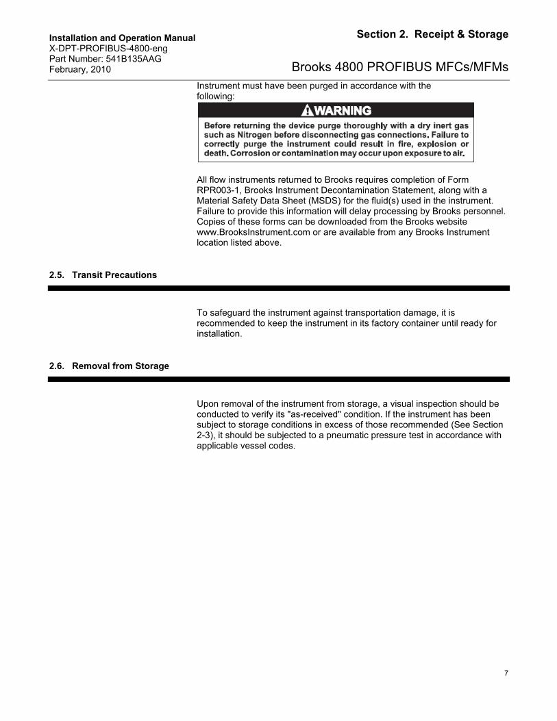
Brooks 4800 PROFIBUS MFCs/MFMsInstrument must have been purged in accordance with the following:
All flow instruments returned to Brooks requires completion of Form RPR003-1, Brooks Instrument Decontamination Statement, along with a Material Safety Data Sheet (MSDS) for the fluid(s) used in the instrument. Failure to provide this information will delay processing by Brooks personnel. Copies of these forms can be downloaded from the Brooks website www.BrooksInstrument.com or are available from any Brooks Instrument location listed above.
2.5. Transit Precautions
To safeguard the instrument against transportation damage, it is recommended to keep the instrument in its factory container until ready for installation.
2.6. Removal from Storage
Upon removal of the instrument from storage, a visual inspection should be conducted to verify its "as-received" condition. If the instrument has been subject to storage conditions in excess of those recommended (See Section 2-3), it should be subjected to a pneumatic pressure test in accordance with applicable vessel codes.

Installation and Operation Manual X-DPT-PROFIBUS-4800-eng Part Number: 541B135AAG February, 2010
8
Section 2. Receipt & Storage
Brooks 4800 PROFIBUS MFCs/MFMs
THIS PAGE WAS INTENTIONALLY
LEFT BLANK
Installation and Operation Manual X-DPT-PROFIBUS-4800-eng Part Number: 541B135AAG February, 2010
9
Section 3. Background & Numbering
Brooks 4800 PROFIBUS MFCs/MFMs
3. Background & Numbering
3.1. Background & Assumptions
This manual is a supplement to the Brooks 4800 Series installation and operation manual. It is assumed that the owner of this 48xx PROFIBUS MFC/MFM is thoroughly familiar with the theory and operation of this device. If not, it is recommended that the owner reads the installation and operation manual first before continuing with this supplement.
This manual assumes basic knowledge and understanding of PROFIBUS (its topology and its method of logically accessing the data or parameters contained within the device). This manual is not intended to be a replacement to the PROFIBUS specifications. It is recommended but not required for the purposes of this manual, that the user obtains a copy of the PROFIBUS specifications (www.PROFIBUS.com).
This manual does not make any assumptions about any particular manufacturer of equipment or custom software used by the user to communicate with the Brooks device, but assumes the user has thorough understanding of such equipment and any configuration software. Application Notes and FAQ’s are available at the Brooks Instrument web site (www.BrooksInstrument.com).
3.2. Numbers
Numeric values used throughout this manual will be clearly denoted as to the base numeric system it represents. All hexadecimal numbers (base 16) will be prefixed with a 0x, like 0xA4. All binary numbers (base 2) will be suffixed with a b, like 1001b. All other numbers not annotated this way will be assumed decimal (base 10).

Installation and Operation Manual X-DPT-PROFIBUS-4800-eng Part Number: 541B135AAG February, 2010
10
Section 3. Background & Numbering
Brooks 4800 PROFIBUS MFCs/MFMs
THIS PAGE WAS INTENTIONALLY
LEFT BLANK
Installation and Operation Manual X-DPT-PROFIBUS-4800-eng Part Number: 541B135AAG February, 2010
11
Section 4. Installation
Brooks 4800 PROFIBUS MFCs/MFMs
4. Installation
This section assumes the owner of the Digital Series device has a fully operational and trouble-free communications network with appropriate power supplies (15-24V depending on the 48xx device type). This section also assumes that one or two master type of devices are connected to the PROFIBUS network capable of DPV0 cyclic and DPV1 acyclic data communication. Both types of data communication modes are supported by the Brooks 48xx PROFIBUS device.
4.1. Supported Baud rates
Data communication can be performed at a number of baud rates: 9600, 19.2K, 45.45K, 93.75K, 187.5K, 500K, 1.5M, 3M, 6M and 12M baud. The communication electronics allows for automatic baud rate detection, thus making the need for any hardware baud rate selection methods not required.
4.2. Address Selection
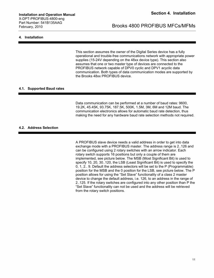
A PROFIBUS slave device needs a valid address in order to get into data exchange mode with a PROFIBUS master. The address range is 2..126 and can be configured using 2 rotary switches with an arrow indicator. Each rotary switch supports 16 positions but only a couple of them are implemented, see picture below. The MSB (Most Significant Bit) is used to specify 10, 20, 30..120, the LSB (Least Significant Bit) is used to specify the 0, 1, 2.. 9. Default the address selectors will be set to the P (Programmable) position for the MSB and the 0 position for the LSB, see picture below. The P position allows for using the “Set Slave” functionality of a class 2 master device to change the default address, i.e. 126, to an address in the range of 2..125. If the rotary switches are configured into any other position than P the “Set Slave” functionality can not be used and the address will be retrieved from the rotary switch positions.
Installation and Operation Manual X-DPT-PROFIBUS-4800-eng Part Number: 541B135AAG February, 2010
12
Section 4. Installation
Brooks 4800 PROFIBUS MFCs/MFMs
Figure 4-1 PROFIBUS Label on Cover
4.3. Bus and Device LEDs
The device supports a Bus and Device LED to indicate the status of network communication and the device. The Bus LED will indicate the following:
Table 4-1 Bus Led Specification
Flash Code Description
Off No Network Connected
Flashing Green Network Connected
Solid Green Communications Established (DP and/or V1)
Flashing Red Configuration Error
Flashing Red/Green
Parameterization Error
Solid Red Hardware Error
The Device LED will indicate the following:
Table 4-2 Device Led Specification
Flash Code Description Flashing Red/Green
The device is in the Self-Test mode
Solid Green All self-tests have passed. No faults have been detected
Flashing Red A recoverable fault has been detected or the device has been commanded into the Abort state
Solid Red An unrecoverable fault has occurred
Installation and Operation Manual X-DPT-PROFIBUS-4800-eng Part Number: 541B135AAG February, 2010
13
Section 4. Installation
Brooks 4800 PROFIBUS MFCs/MFMs
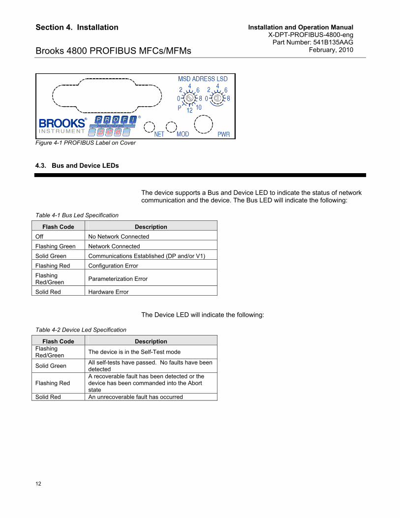
4.4. Profibus Bus signals
Below you’ll find the pin layout of the 9 pins Profibus D-sub connector.
Figure 4-2 Profibus 9 pin D-sub connector
Table 4-3 Profibus 9 pin D-sub layout
Pin Signal 1 Shield 2 Not connected 3 RxD/Txd - B - red wire 4 Not connected 5 Ground 6 +5Vdc 7 Not connected 8 RxD/Txd - A - green wire 9 Not connected
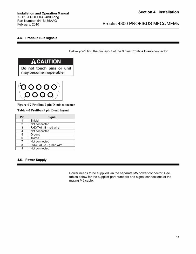
4.5. Power Supply
Power needs to be supplied via the separate M5 power connector. See tables below for the supplier part numbers and signal connections of the mating M5 cable.
Installation and Operation Manual X-DPT-PROFIBUS-4800-eng Part Number: 541B135AAG February, 2010
14
Section 4. Installation
Brooks 4800 PROFIBUS MFCs/MFMs
Figure 4-3 M5 Mating Connector and Cable Specifications
Table 4-4 M5 Mating Connector Supplier Part Numbers
Supplier Part Number Description
124x035ZZZ Female M5 connector with 2m cable Brooks Instrument
124x036ZZZ Female M5 connector with 5m cable
Table 4-5 Signal Definitions
Signal Description
Brown +V
Blue GND
Black Not used
Installation and Operation Manual X-DPT-PROFIBUS-4800-eng Part Number: 541B135AAG February, 2010
15
Section 5. Slave Configuration
Brooks 4800 PROFIBUS MFCs/MFMs
5. Slave Configuration
5.1. Introduction
The purpose of the PROFIBUS field bus system is to exchange data between the master and its slave devices. In addition to Input/Output data which are exchanged when the slave device is in data exchange mode, also parameter, configuration and diagnostic data is transferred.
Many PROFIBUS masters need a configuration program to setup the PROFIBUS network and configure slave devices, e.g. Siemens Step7 for the S7 controller. These programs require a device configuration file called GSD file. To download the GSD file for the Brooks Instrument 4800 Series go to www.Profibus.com and enter the Products section and select Product Guide. Enter “Brooks Instrument” into the “Full Text Search” box and hit enter or click the search arrow. Scroll down and click the view product icon(magnifying glass icon). The downloadable GSD file is at the bottom of the page ( www.Profibus.com/nc/products/product-guide/product/display/digital-thermal-mass-flow-metercontroller/5/1/).
For the PROFIBUS network configuration of the 48xx Series PROFIBUS devices the following GSD file is provided:
BIMF4800.GSD – 48xx Series Mass Flow Controller/Meter
5.2. Parameterization of the Slave (48xx Series MFC/MFM)
During the initialisation phase of the slave device the master configures the slave with the so called user parameters, this part of the initialisation phase is called the parameterization. Using the master configuration program these user parameters can be changed, giving the slave device a different configuration during initialisation.
Installation and Operation Manual X-DPT-PROFIBUS-4800-eng Part Number: 541B135AAG February, 2010
16
Section 5. Slave Configuration
Brooks 4800 PROFIBUS MFCs/MFMs
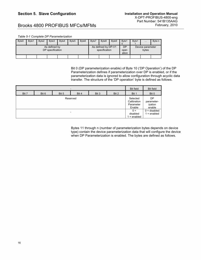
Table 5-1 Complete DP Parameterization
Byte0 Byte1 Byte2 Byte3 Byte4 Byte5 Byte6 Byte7 Byte8 Byte9 Byte10
Byte11
… Byte-n
As defined by DP specification
As defined by DP-V1 specification
DP oper-ation
Device parameter bytes
Bit 0 (DP parameterization enable) of Byte 10 (‘DP Operation’) of the DP Parameterization defines if parameterization over DP is enabled, or if the parameterization data is ignored to allow configuration through acyclic data transfer. The structure of the ‘DP operation’ byte is defined as follows.
- Bit field Bit field
Bit 7 Bit 6 Bit 5 Bit 4 Bit 3 Bit 2 Bit 1 Bit 0
Reserved Selected Calibration Parameter
Enable
DP parameter-
ization enable
- 0 = disabled
1 = enabled
0 = disabled 1 = enabled
Bytes 11 through n (number of parameterization bytes depends on device type) contain the device parameterization data that will configure the device when DP Parameterization is enabled. The bytes are defined as follows.
Installation and Operation Manual X-DPT-PROFIBUS-4800-eng Part Number: 541B135AAG February, 2010
17
Section 5. Slave Configuration
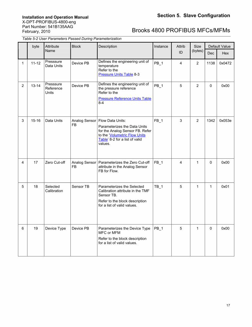
Brooks 4800 PROFIBUS MFCs/MFMsTable 5-2 User Parameters Passed During Parameterization
Default Value byte Attribute Name
Block Description Instance Attrib
ID
Size (bytes)
Dec Hex
1 11-12 Presssure Data Units
Device PB Defines the engineering unit of temperature Refer to the Pressure Units Table 8-3
PB_1 4 2 1138 0x0472
2 13-14 Presssure Reference Units
Device PB Defines the engineering unit of the pressure reference Refer to the
Pressure Reference Units Table 8-4
PB_1 5 2 0 0x00
3 15-16 Data Units Analog Sensor FB
Flow Data Units:
Parameterizes the Data Units for the Analog Sensor FB. Refer to the ‘Volumetric Flow Units Table’ 8-2 for a list of valid values.
FB_1 3 2 1342 0x053e
4 17 Zero Cut-off Analog Sensor FB
Parameterizes the Zero Cut-off attribute in the Analog Sensor FB for Flow.
FB_1 4 1 0 0x00
5 18 Selected Calibration
Sensor TB Parameterizes the Selected Calibration attribute in the TMF Sensor TB.
Refer to the block description for a list of valid values.
TB_1 5 1 1 0x01
6 19 Device Type Device PB Parameterizes the Device Type MFC or MFM
Refer to the block description for a list of valid values.
PB_1 5 1 0 0x00
Installation and Operation Manual X-DPT-PROFIBUS-4800-eng Part Number: 541B135AAG February, 2010
18
Section 5. Slave Configuration
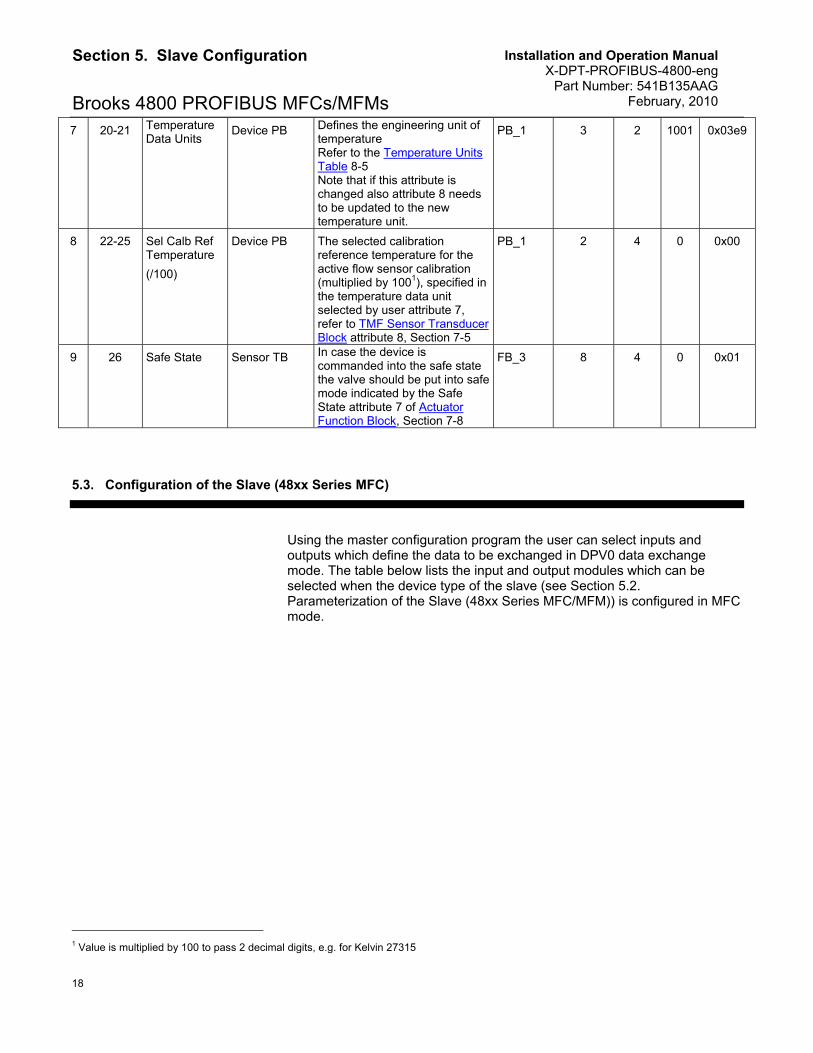
Brooks 4800 PROFIBUS MFCs/MFMs 7 20-21 Temperature
Data Units Device PB Defines the engineering unit of
temperature Refer to the Temperature Units Table 8-5 Note that if this attribute is changed also attribute 8 needs to be updated to the new temperature unit.
PB_1 3 2 1001 0x03e9
8 22-25 Sel Calb Ref Temperature
(/100)
Device PB The selected calibration reference temperature for the active flow sensor calibration (multiplied by 1001), specified in the temperature data unit selected by user attribute 7, refer to TMF Sensor Transducer Block attribute 8, Section 7-5
PB_1 2 4 0 0x00
9 26 Safe State Sensor TB In case the device is commanded into the safe state the valve should be put into safe mode indicated by the Safe State attribute 7 of Actuator Function Block, Section 7-8
FB_3 8 4 0
0x01
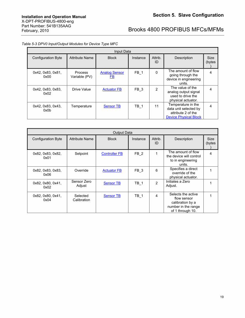
5.3. Configuration of the Slave (48xx Series MFC)
Using the master configuration program the user can select inputs and outputs which define the data to be exchanged in DPV0 data exchange mode. The table below lists the input and output modules which can be selected when the device type of the slave (see Section 5.2. Parameterization of the Slave (48xx Series MFC/MFM)) is configured in MFC mode.
1 Value is multiplied by 100 to pass 2 decimal digits, e.g. for Kelvin 27315
Installation and Operation Manual X-DPT-PROFIBUS-4800-eng Part Number: 541B135AAG February, 2010
19
Section 5. Slave Configuration
Brooks 4800 PROFIBUS MFCs/MFMs
Table 5-3 DPV0 Input/Output Modules for Device Type MFC
Input Data
Configuration Byte Attribute Name Block Instance Attrib. ID
Description Size (bytes
)
0x42, 0x83, 0x81, 0x00
Process Variable (PV)
Analog Sensor FB
FB_1 0 The amount of flow going through the
device in engineering units.
4
0x42, 0x83, 0x83, 0x02
Drive Value Actuator FB FB_3 2 The value of the analog output signal
used to drive the physical actuator.
4
0x42, 0x83, 0x43, 0x0b
Temperature Sensor TB TB_1 11 Temperature in the data unit selected by
attribute 2 of the Device Physical Block
4
Output Data
Configuration Byte Attribute Name Block Instance Attrib. ID
Description Size (bytes
)
0x82, 0x83, 0x82, 0x01
Setpoint Controller FB FB_2 1 The amount of flow the device will control
to in engineering units.
4
0x82, 0x83, 0x83, 0x06
Override Actuator FB FB_3 6 Specifies a direct override of the
physical actuator.
1
0x82, 0x80, 0x41, 0x02
Sensor Zero Adjust
Sensor TB TB_1 2 Initiates a Zero Adjust.
1
0x82, 0x80, 0x41, 0x04
Selected Calibration
Sensor TB TB_1 4 Selects the active flow sensor
calibration by a number in the range
of 1 through 10.
1
Installation and Operation Manual X-DPT-PROFIBUS-4800-eng Part Number: 541B135AAG February, 2010
20
Section 5. Slave Configuration
Brooks 4800 PROFIBUS MFCs/MFMs
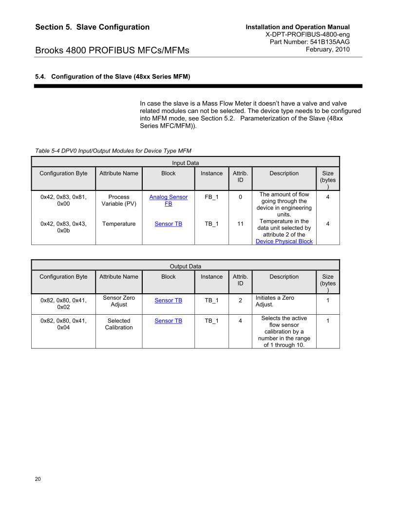
5.4. Configuration of the Slave (48xx Series MFM)
In case the slave is a Mass Flow Meter it doesn’t have a valve and valve related modules can not be selected. The device type needs to be configured into MFM mode, see Section 5.2. Parameterization of the Slave (48xx Series MFC/MFM)).
Table 5-4 DPV0 Input/Output Modules for Device Type MFM
Input Data
Configuration Byte Attribute Name Block Instance Attrib. ID
Description Size (bytes
)
0x42, 0x83, 0x81, 0x00
Process Variable (PV)
Analog Sensor FB
FB_1 0 The amount of flow going through the
device in engineering units.
4
0x42, 0x83, 0x43, 0x0b
Temperature Sensor TB TB_1 11 Temperature in the data unit selected by
attribute 2 of the Device Physical Block
4
Output Data
Configuration Byte Attribute Name Block Instance Attrib. ID
Description Size (bytes
)
0x82, 0x80, 0x41, 0x02
Sensor Zero Adjust
Sensor TB TB_1 2 Initiates a Zero Adjust.
1
0x82, 0x80, 0x41, 0x04
Selected Calibration
Sensor TB TB_1 4 Selects the active flow sensor
calibration by a number in the range
of 1 through 10.
1
Installation and Operation Manual X-DPT-PROFIBUS-4800-eng Part Number: 541B135AAG February, 2010
21
Section 5. Slave Configuration
Brooks 4800 PROFIBUS MFCs/MFMs
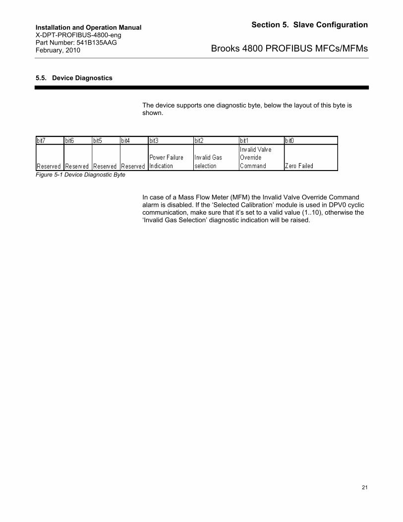
5.5. Device Diagnostics
The device supports one diagnostic byte, below the layout of this byte is shown.
Figure 5-1 Device Diagnostic Byte
In case of a Mass Flow Meter (MFM) the Invalid Valve Override Command alarm is disabled. If the ‘Selected Calibration’ module is used in DPV0 cyclic communication, make sure that it’s set to a valid value (1..10), otherwise the ‘Invalid Gas Selection’ diagnostic indication will be raised.

Installation and Operation Manual X-DPT-PROFIBUS-4800-eng Part Number: 541B135AAG February, 2010
22
Section 5. Slave Configuration
Brooks 4800 PROFIBUS MFCs/MFMs
THIS PAGE WAS INTENTIONALLY
LEFT BLANK
Installation and Operation Manual X-DPT-PROFIBUS-4800-eng Part Number: 541B135AAG February, 2010
23
Section 6. DPV0 Cyclic Data Exchange
Brooks 4800 PROFIBUS MFCs/MFMs
6. DPV0 Cyclic Data Exchange
Once the device has gone through the parameterization and DPV0 input and output modules have been selected the master will direct the slave into DPV0 cyclic data exchange mode, see 5.3. Configuration of the Slave (48xx Series MFC) and 5.4. Configuration of the Slave (48xx Series MFM). In this mode data is exchanged between master and slave on a periodic basis. The input is data which is going from slave to master and output is data which is going from master to slave.

Installation and Operation Manual X-DPT-PROFIBUS-4800-eng Part Number: 541B135AAG February, 2010
24
Section 6. DPV0 Cyclic Data Exchange
Brooks 4800 PROFIBUS MFCs/MFMs
THIS PAGE WAS INTENTIONALLY
LEFT BLANK
Installation and Operation Manual X-DPT-PROFIBUS-4800-eng Part Number: 541B135AAG February, 2010
25
Section 7. DPV1 Acyclic Data Communication
Brooks 4800 PROFIBUS MFCs/MFMs
7. DPV1 Acyclic Data Communication
7.1. Device Block Model
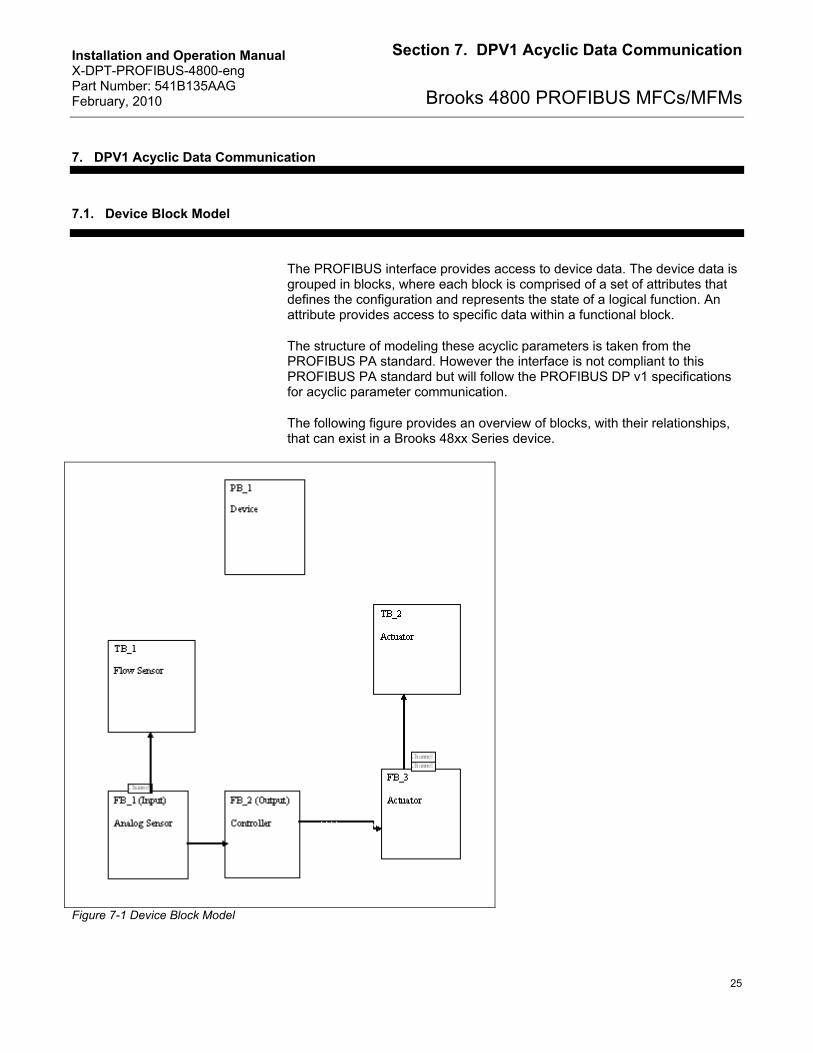
The PROFIBUS interface provides access to device data. The device data is grouped in blocks, where each block is comprised of a set of attributes that defines the configuration and represents the state of a logical function. An attribute provides access to specific data within a functional block.
The structure of modeling these acyclic parameters is taken from the PROFIBUS PA standard. However the interface is not compliant to this PROFIBUS PA standard but will follow the PROFIBUS DP v1 specifications for acyclic parameter communication.
The following figure provides an overview of blocks, with their relationships, that can exist in a Brooks 48xx Series device.
Figure 7-1 Device Block Model
Installation and Operation Manual X-DPT-PROFIBUS-4800-eng Part Number: 541B135AAG February, 2010
26
Section 7. DPV1 Acyclic Data Communication
Brooks 4800 PROFIBUS MFCs/MFMs
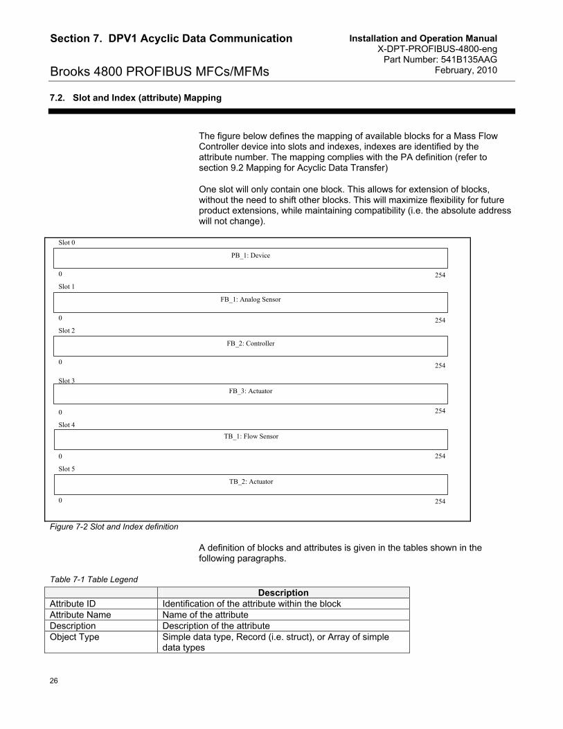
7.2. Slot and Index (attribute) Mapping
The figure below defines the mapping of available blocks for a Mass Flow Controller device into slots and indexes, indexes are identified by the attribute number. The mapping complies with the PA definition (refer to section 9.2 Mapping for Acyclic Data Transfer)
One slot will only contain one block. This allows for extension of blocks, without the need to shift other blocks. This will maximize flexibility for future product extensions, while maintaining compatibility (i.e. the absolute address will not change).
0
0
254
Slot 0
PB_1: Device
254
Slot 1
FB_1: Analog Sensor
254
Slot 2
254
Slot 3
FB_3: Actuator
0 254
Slot 4
TB_1: Flow Sensor
254 0
Slot 5
TB_2: Actuator
0
0
FB_2: Controller
Figure 7-2 Slot and Index definition
A definition of blocks and attributes is given in the tables shown in the following paragraphs.
Table 7-1 Table Legend
Description Attribute ID Identification of the attribute within the block Attribute Name Name of the attribute Description Description of the attribute Object Type Simple data type, Record (i.e. struct), or Array of simple
data types
Installation and Operation Manual X-DPT-PROFIBUS-4800-eng Part Number: 541B135AAG February, 2010
27
Section 7. DPV1 Acyclic Data Communication
Brooks 4800 PROFIBUS MFCs/MFMs
Data Type Data format as defined in document ‘PROFIBUS DP Extensions to EN 50170, paragraph 10.5’.
Storage Storage definition: Non-volatile, Dynamic (i.e. volatile) or Constant (no Static parameters are supported).
Number of Bytes Data length in bytes Access readable and/or writable DP Data Exchange Defines if the attribute is accessible as an Input or Output
parameter though cyclic data exchange (DP) DP Param Defines if the attribute can (P) or cannot (-) be set through
the DP parameterization service
When the user requests an attribute from a block which is not supported by the configured device type (MFC/MFM) an invalid parameter response will be returned.
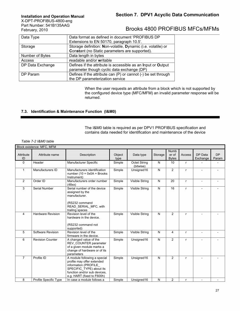
7.3. Identification & Maintenance Function (I&M0)
The I&M0 table is required as per DPV1 PROFIBUS specification and contains data needed for identification and maintenance of the device
Table 7-2 I&M0 table
Block existence: MFC, MFM
Attribute ID
Attribute name
Description
Object type
Data type
Storage
Number of Bytes
Access
DP Data
Exchange
DP
Param 0 Header Manufacturer Specific Simple Octet String
(bitwise) N 10 r - -
1 Manufacturers ID Manufacturers identification number (10 = 0x0A = Brooks Instrument)
Simple Unsigned16 N 2 r - -
2 Order ID Manufacturers order number (48xx)
Simple Visible String N 20 r - -
3 Serial Number Serial number of the device assigned by the manufacturer. (RS232 command READ_SERIAL_MFC, with trailing spaces
Simple Visible String N 16 r - -
4 Hardware Revision Revision level of the hardware in the device. (RS232 command not supported)
Simple Visible String N 2 r - -
5 Software Revision Revision level of the firmware in the device.
Simple Visible String N 4 r - -
6 Revision Counter A changed value of the REV_COUNTER parameter of a given module marks a change of hardware or of its parameters
Simple Unsigned16 N 2 r - -
7 Profile ID A module following a special profile may offer extended information (PROFILE_ SPECIFIC_TYPE) about its function and/or sub devices, e.g. HART (fixed to F600h)
Simple Unsigned16 N 2 r - -
8 Profile Specific Type In case a module follows a Simple Unsigned16 N 2 r - -
Installation and Operation Manual X-DPT-PROFIBUS-4800-eng Part Number: 541B135AAG February, 2010
28
Section 7. DPV1 Acyclic Data Communication
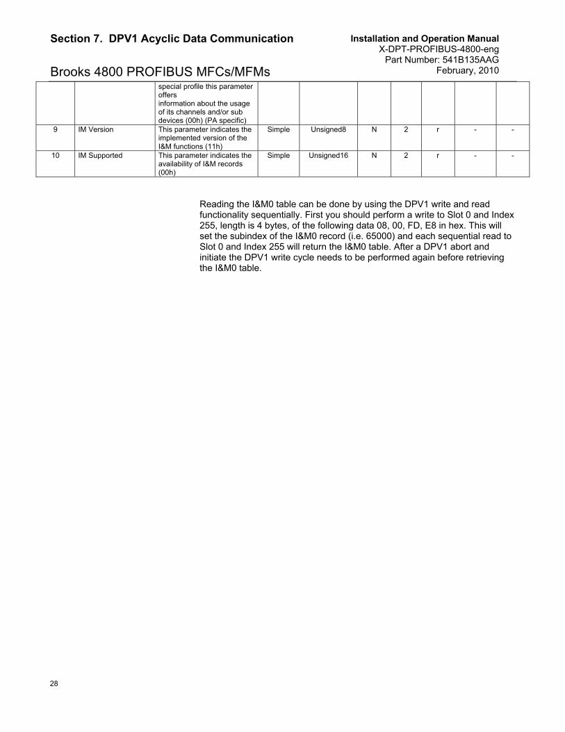
Brooks 4800 PROFIBUS MFCs/MFMs special profile this parameter offers information about the usage of its channels and/or sub devices (00h) (PA specific)
9 IM Version This parameter indicates the implemented version of the I&M functions (11h)
Simple Unsigned8 N 2 r - -
10 IM Supported This parameter indicates the availability of I&M records (00h)
Simple Unsigned16 N 2 r - -
Reading the I&M0 table can be done by using the DPV1 write and read functionality sequentially. First you should perform a write to Slot 0 and Index 255, length is 4 bytes, of the following data 08, 00, FD, E8 in hex. This will set the subindex of the I&M0 record (i.e. 65000) and each sequential read to Slot 0 and Index 255 will return the I&M0 table. After a DPV1 abort and initiate the DPV1 write cycle needs to be performed again before retrieving the I&M0 table.
Installation and Operation Manual X-DPT-PROFIBUS-4800-eng Part Number: 541B135AAG February, 2010
29
Section 7. DPV1 Acyclic Data Communication
Brooks 4800 PROFIBUS MFCs/MFMs
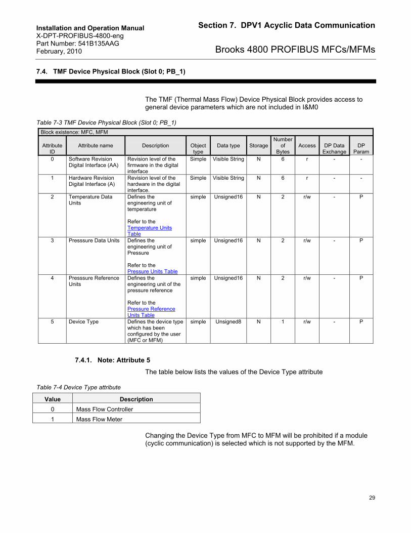
7.4. TMF Device Physical Block (Slot 0; PB_1)
The TMF (Thermal Mass Flow) Device Physical Block provides access to general device parameters which are not included in I&M0
Table 7-3 TMF Device Physical Block (Slot 0; PB_1)
Block existence: MFC, MFM
Attribute ID
Attribute name
Description
Object type
Data type
Storage
Number of
Bytes
Access
DP Data
Exchange
DP
Param 0 Software Revision
Digital Interface (AA) Revision level of the firmware in the digital interface
Simple Visible String N 6 r - -
1 Hardware Revision Digital Interface (A)
Revision level of the hardware in the digital interface.
Simple Visible String N 6 r - -
2 Temperature Data Units
Defines the engineering unit of temperature Refer to the Temperature Units Table
simple Unsigned16 N 2 r/w - P
3 Presssure Data Units Defines the engineering unit of Pressure Refer to the Pressure Units Table
simple Unsigned16 N 2 r/w - P
4 Presssure Reference Units
Defines the engineering unit of the pressure reference Refer to the Pressure Reference Units Table
simple Unsigned16 N 2 r/w - P
5 Device Type Defines the device type which has been configured by the user (MFC or MFM)
simple Unsigned8 N 1 r/w - P
7.4.1. Note: Attribute 5
The table below lists the values of the Device Type attribute
Table 7-4 Device Type attribute
Value Description
0 Mass Flow Controller
1 Mass Flow Meter
Changing the Device Type from MFC to MFM will be prohibited if a module (cyclic communication) is selected which is not supported by the MFM.
Installation and Operation Manual X-DPT-PROFIBUS-4800-eng Part Number: 541B135AAG February, 2010
30
Section 7. DPV1 Acyclic Data Communication
Brooks 4800 PROFIBUS MFCs/MFMs
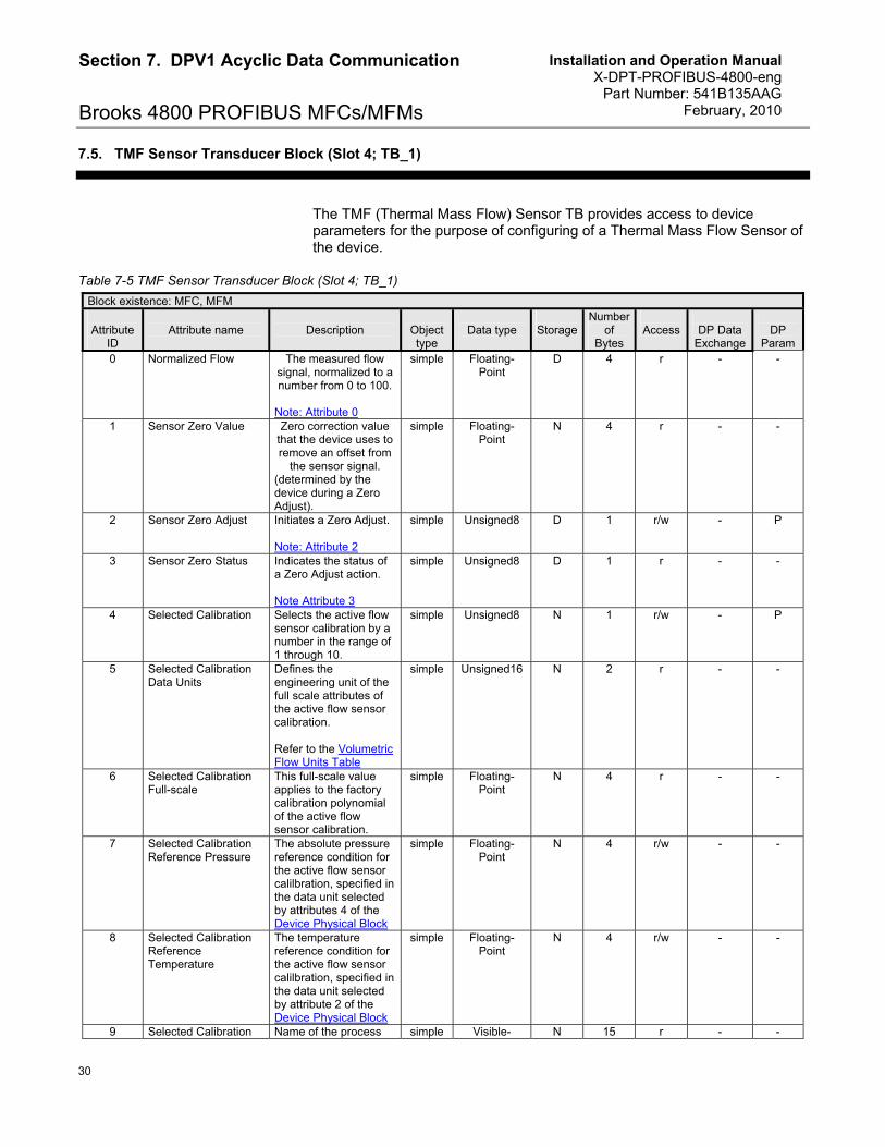
7.5. TMF Sensor Transducer Block (Slot 4; TB_1)
The TMF (Thermal Mass Flow) Sensor TB provides access to device parameters for the purpose of configuring of a Thermal Mass Flow Sensor of the device.
Table 7-5 TMF Sensor Transducer Block (Slot 4; TB_1)
Block existence: MFC, MFM
Attribute ID
Attribute name
Description
Object type
Data type
Storage
Number of
Bytes
Access
DP Data
Exchange
DP
Param 0 Normalized Flow The measured flow
signal, normalized to a number from 0 to 100.
Note: Attribute 0
simple Floating-Point
D 4 r - -
1 Sensor Zero Value Zero correction value that the device uses to remove an offset from
the sensor signal. (determined by the device during a Zero Adjust).
simple Floating-Point
N 4 r - -
2 Sensor Zero Adjust Initiates a Zero Adjust. Note: Attribute 2
simple Unsigned8 D 1 r/w - P
3 Sensor Zero Status Indicates the status of a Zero Adjust action. Note Attribute 3
simple Unsigned8 D 1 r - -
4 Selected Calibration Selects the active flow sensor calibration by a number in the range of 1 through 10.
simple Unsigned8 N 1 r/w - P
5 Selected Calibration Data Units
Defines the engineering unit of the full scale attributes of the active flow sensor calibration. Refer to the Volumetric Flow Units Table
simple Unsigned16 N 2 r - -
6 Selected Calibration Full-scale
This full-scale value applies to the factory calibration polynomial of the active flow sensor calibration.
simple Floating-Point
N 4 r - -
7 Selected Calibration Reference Pressure
The absolute pressure reference condition for the active flow sensor calilbration, specified in the data unit selected by attributes 4 of the Device Physical Block
simple Floating-Point
N 4 r/w - -
8 Selected Calibration Reference Temperature
The temperature reference condition for the active flow sensor calilbration, specified in the data unit selected by attribute 2 of the Device Physical Block
simple Floating-Point
N 4 r/w - -
9 Selected Calibration Name of the process simple Visible- N 15 r - -
Installation and Operation Manual X-DPT-PROFIBUS-4800-eng Part Number: 541B135AAG February, 2010
31
Section 7. DPV1 Acyclic Data Communication
Brooks 4800 PROFIBUS MFCs/MFMsGas Name gas of the active flow
sensor calibration. String
10 Selected Calibration Gas Density
Gas density [gm/m3] Simple Floating-Point
N 4 r
11 Temperature Temperature specified in the data unit selected by attribute 2 of the Device Physical Block
Simple Floating-Point
N 4 r I
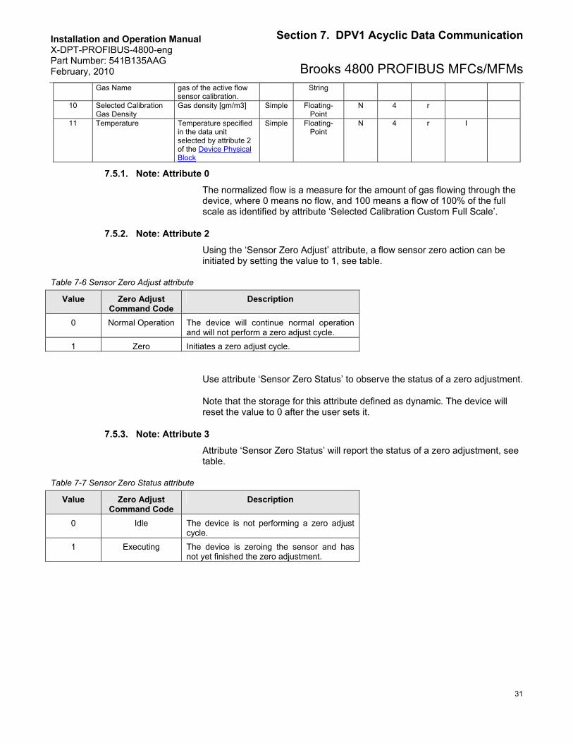
7.5.1. Note: Attribute 0
The normalized flow is a measure for the amount of gas flowing through the device, where 0 means no flow, and 100 means a flow of 100% of the full scale as identified by attribute ‘Selected Calibration Custom Full Scale’.
7.5.2. Note: Attribute 2
Using the ‘Sensor Zero Adjust’ attribute, a flow sensor zero action can be initiated by setting the value to 1, see table.
Table 7-6 Sensor Zero Adjust attribute
Value Zero Adjust Command Code
Description
0 Normal Operation The device will continue normal operation and will not perform a zero adjust cycle.
1 Zero Initiates a zero adjust cycle.
Use attribute ‘Sensor Zero Status’ to observe the status of a zero adjustment.
Note that the storage for this attribute defined as dynamic. The device will reset the value to 0 after the user sets it.
7.5.3. Note: Attribute 3
Attribute ‘Sensor Zero Status’ will report the status of a zero adjustment, see table.
Table 7-7 Sensor Zero Status attribute
Value Zero Adjust Command Code
Description
0 Idle The device is not performing a zero adjust cycle.
1 Executing The device is zeroing the sensor and has not yet finished the zero adjustment.
Installation and Operation Manual X-DPT-PROFIBUS-4800-eng Part Number: 541B135AAG February, 2010
32
Section 7. DPV1 Acyclic Data Communication
Brooks 4800 PROFIBUS MFCs/MFMs 7.5.4. Note: Attribute 9
The table below lists the corresponding Gas Name.
Table 7-8 List of Gas Names
Gas Symbol Gas Name He Helium Ar Argon H2 Hydrogen Air Air CO Carbon Monoxide N2 Nitrogen O2 Oxygen
CO2 Carbon Dioxide N2O Nitrous Oxide CH4 Methane C3H6 Propene C3H8 Propane
7.6. Analog Sensor Function Block (Slot 1; FB_1)
Table 7-9 Analog Sensor Function Block (Slot 1; FB_1)
Block existence: MFC, MFM
Attribute ID
Attribute name
Description
Object type
Data type
Storage
Number of
Bytes
Access
DP Data
Exchange
DP
Param 0 Process Variable (PV) The amount of flow
through the device. This value is corrected, converted and calibrated to report the actual value of flow in the engineering units configured by attribute ‘Data Units’.
Simple Floating-Point
D 4 r I -
1 PV Channel2 Reference to the Sensor Transducer Block that provides the measurement value to this function block Fixed to 0x0400
Simple Unsigned16 N 2 r - -
2 Data Units Defines the Engineering Units context of attributes ‘Process Variable’. Refer to the Volumetric Flow Units Table
Simple Unsigned16 N 2 r/w - P
3 Zero Cut-off Defines a threshold near zero such that if the flow measurement goes below this threshold, the ‘Process Variable’ will report
Simple Boolean N 1 r/w - P
2 Reference is a slot (MSB) and attribute (LSB) combination
Installation and Operation Manual X-DPT-PROFIBUS-4800-eng Part Number: 541B135AAG February, 2010
33
Section 7. DPV1 Acyclic Data Communication
Brooks 4800 PROFIBUS MFCs/MFMszero. Supported values: True = 1% False = 0%
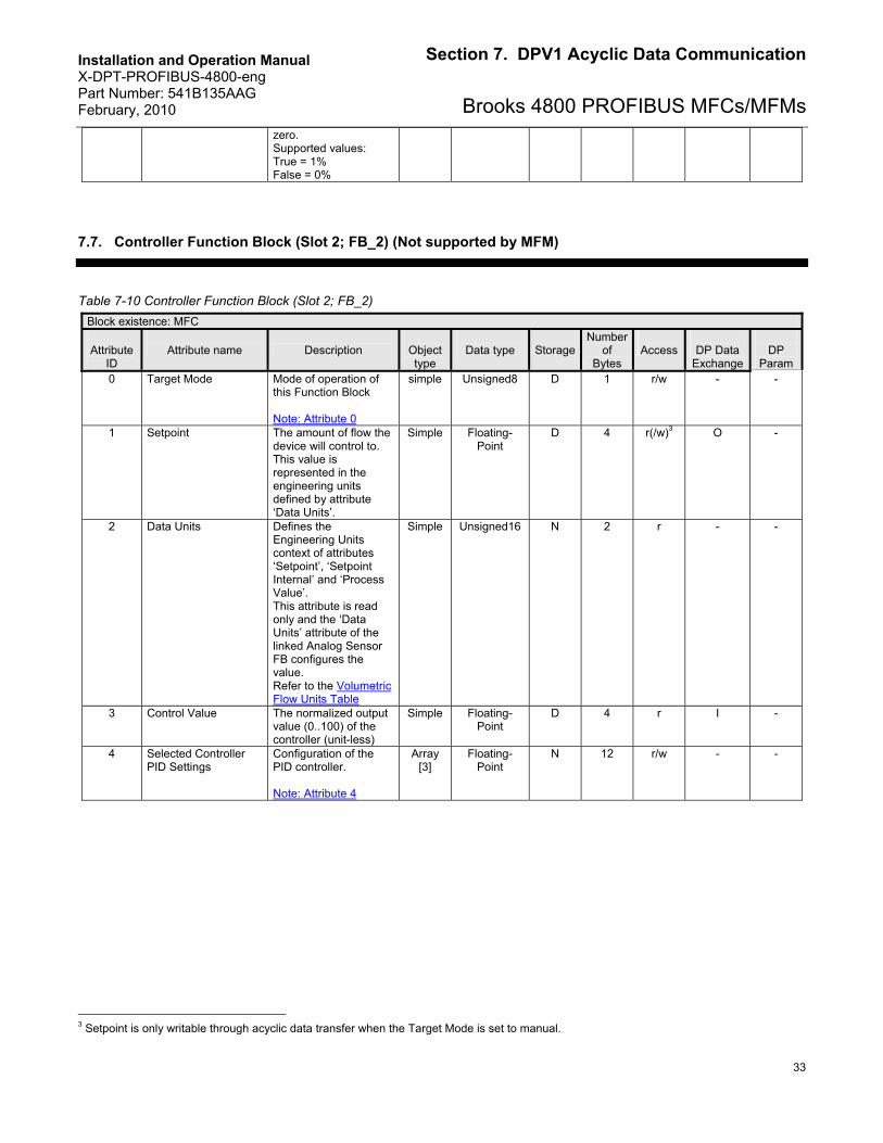
7.7. Controller Function Block (Slot 2; FB_2) (Not supported by MFM)
Table 7-10 Controller Function Block (Slot 2; FB_2)
Block existence: MFC
Attribute ID
Attribute name Description
Object type
Data type
Storage
Number of
Bytes
Access
DP Data
Exchange
DP
Param 0 Target Mode Mode of operation of
this Function Block Note: Attribute 0
simple Unsigned8 D 1 r/w - -
1 Setpoint The amount of flow the device will control to. This value is represented in the engineering units defined by attribute ‘Data Units’.
Simple Floating-Point
D 4 r(/w)3 O -
2 Data Units Defines the Engineering Units context of attributes ‘Setpoint’, ‘Setpoint Internal’ and ‘Process Value’. This attribute is read only and the ‘Data Units’ attribute of the linked Analog Sensor FB configures the value. Refer to the Volumetric Flow Units Table
Simple Unsigned16 N 2 r - -
3 Control Value The normalized output value (0..100) of the controller (unit-less)
Simple Floating-Point
D 4 r I -
4 Selected Controller PID Settings
Configuration of the PID controller. Note: Attribute 4
Array [3]
Floating-Point
N 12 r/w - -
3 Setpoint is only writable through acyclic data transfer when the Target Mode is set to manual.
Installation and Operation Manual X-DPT-PROFIBUS-4800-eng Part Number: 541B135AAG February, 2010
34
Section 7. DPV1 Acyclic Data Communication
Brooks 4800 PROFIBUS MFCs/MFMs
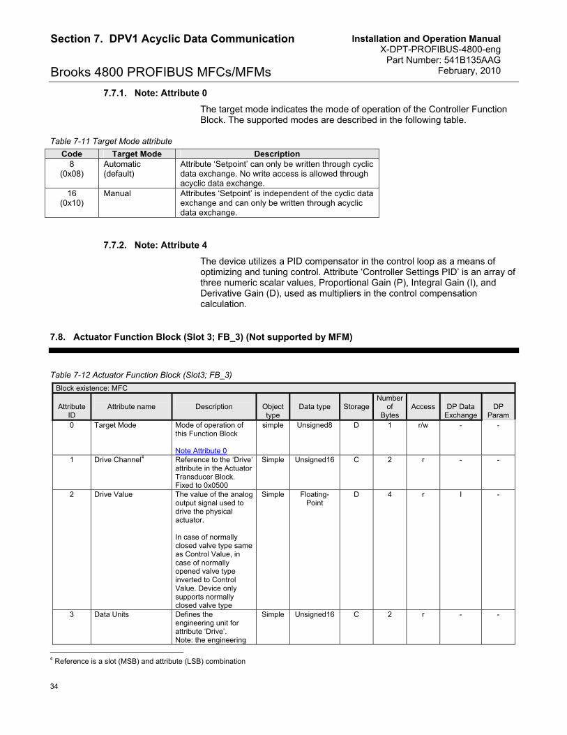
7.7.1. Note: Attribute 0
The target mode indicates the mode of operation of the Controller Function Block. The supported modes are described in the following table.
Table 7-11 Target Mode attribute
Code Target Mode Description 8
(0x08) Automatic (default)
Attribute ‘Setpoint’ can only be written through cyclic data exchange. No write access is allowed through acyclic data exchange.
16 (0x10)
Manual Attributes ‘Setpoint’ is independent of the cyclic data exchange and can only be written through acyclic data exchange.
7.7.2. Note: Attribute 4
The device utilizes a PID compensator in the control loop as a means of optimizing and tuning control. Attribute ‘Controller Settings PID’ is an array of three numeric scalar values, Proportional Gain (P), Integral Gain (I), and Derivative Gain (D), used as multipliers in the control compensation calculation.
7.8. Actuator Function Block (Slot 3; FB_3) (Not supported by MFM)
Table 7-12 Actuator Function Block (Slot3; FB_3)
Block existence: MFC
Attribute ID
Attribute name
Description
Object type
Data type
Storage
Number of
Bytes
Access
DP Data
Exchange
DP
Param 0 Target Mode Mode of operation of
this Function Block Note Attribute 0
simple Unsigned8 D 1 r/w - -
1 Drive Channel4 Reference to the ‘Drive’ attribute in the Actuator Transducer Block. Fixed to 0x0500
Simple Unsigned16 C 2 r - -
2 Drive Value The value of the analog output signal used to drive the physical actuator. In case of normally closed valve type same as Control Value, in case of normally opened valve type inverted to Control Value. Device only supports normally closed valve type
Simple Floating-Point
D 4 r I -
3 Data Units Defines the engineering unit for attribute ‘Drive’. Note: the engineering
Simple Unsigned16 C 2 r - -
4 Reference is a slot (MSB) and attribute (LSB) combination
Installation and Operation Manual X-DPT-PROFIBUS-4800-eng Part Number: 541B135AAG February, 2010
35
Section 7. DPV1 Acyclic Data Communication
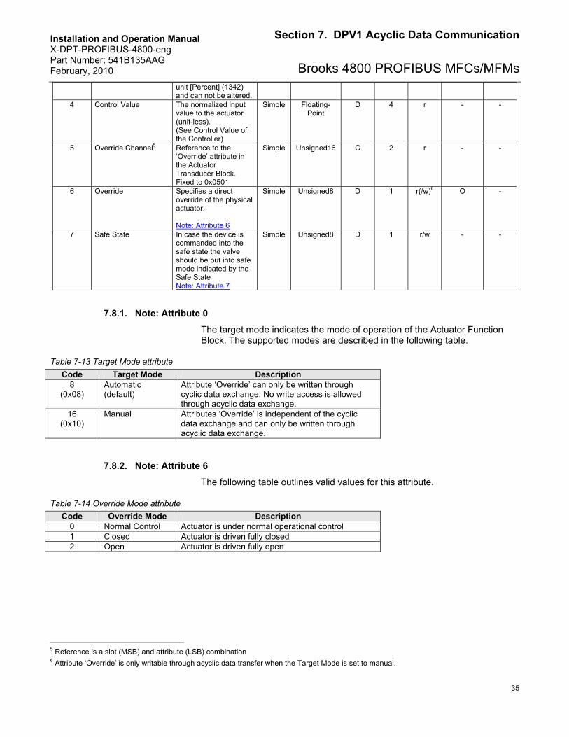
Brooks 4800 PROFIBUS MFCs/MFMsunit [Percent] (1342) and can not be altered.
4 Control Value The normalized input value to the actuator (unit-less). (See Control Value of the Controller)
Simple Floating-Point
D 4 r - -
5 Override Channel5 Reference to the ‘Override’ attribute in the Actuator Transducer Block. Fixed to 0x0501
Simple Unsigned16 C 2 r - -
6 Override Specifies a direct override of the physical actuator. Note: Attribute 6
Simple Unsigned8 D 1 r(/w)6 O -
7 Safe State In case the device is commanded into the safe state the valve should be put into safe mode indicated by the Safe State Note: Attribute 7
Simple Unsigned8 D 1 r/w - -
7.8.1. Note: Attribute 0
The target mode indicates the mode of operation of the Actuator Function Block. The supported modes are described in the following table.
Table 7-13 Target Mode attribute
Code Target Mode Description 8
(0x08) Automatic (default)
Attribute ‘Override’ can only be written through cyclic data exchange. No write access is allowed through acyclic data exchange.
16 (0x10)
Manual Attributes ‘Override’ is independent of the cyclic data exchange and can only be written through acyclic data exchange.
7.8.2. Note: Attribute 6
The following table outlines valid values for this attribute.
Table 7-14 Override Mode attribute
Code Override Mode Description 0 Normal Control Actuator is under normal operational control 1 Closed Actuator is driven fully closed 2 Open Actuator is driven fully open
5 Reference is a slot (MSB) and attribute (LSB) combination 6 Attribute ‘Override’ is only writable through acyclic data transfer when the Target Mode is set to manual.
Installation and Operation Manual X-DPT-PROFIBUS-4800-eng Part Number: 541B135AAG February, 2010
36
Section 7. DPV1 Acyclic Data Communication
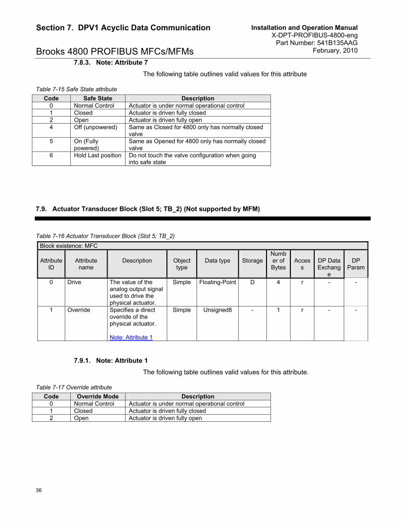
Brooks 4800 PROFIBUS MFCs/MFMs 7.8.3. Note: Attribute 7
The following table outlines valid values for this attribute
Table 7-15 Safe State attribute
Code Safe State Description 0 Normal Control Actuator is under normal operational control 1 Closed Actuator is driven fully closed 2 Open Actuator is driven fully open 4 Off (unpowered) Same as Closed for 4800 only has normally closed
valve 5 On (Fully
powered) Same as Opened for 4800 only has normally closed valve
6 Hold Last position Do not touch the valve configuration when going into safe state
7.9. Actuator Transducer Block (Slot 5; TB_2) (Not supported by MFM)
Table 7-16 Actuator Transducer Block (Slot 5; TB_2)
Block existence: MFC
Attribute ID
Attribute
name
Description
Object type
Data type
Storage
Number of Bytes
Acces
s
DP Data Exchang
e
DP
Param
0 Drive The value of the analog output signal used to drive the physical actuator.
Simple Floating-Point D 4 r - -
1 Override Specifies a direct override of the physical actuator. Note: Attribute 1
Simple Unsigned8 - 1 r - -
7.9.1. Note: Attribute 1
The following table outlines valid values for this attribute.
Table 7-17 Override attribute
Code Override Mode Description 0 Normal Control Actuator is under normal operational control 1 Closed Actuator is driven fully closed 2 Open Actuator is driven fully open
Installation and Operation Manual X-DPT-PROFIBUS-4800-eng Part Number: 541B135AAG February, 2010
37
Section 8. Appendices
Brooks 4800 PROFIBUS MFCs/MFMs
8. Appendices
8.1. Appendix A Data type definitions
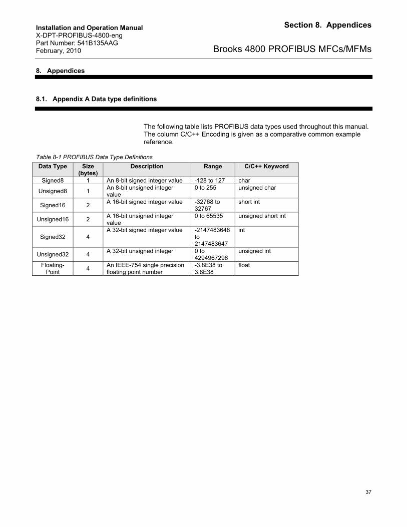
The following table lists PROFIBUS data types used throughout this manual. The column C/C++ Encoding is given as a comparative common example reference.
Table 8-1 PROFIBUS Data Type Definitions
Data Type Size (bytes)
Description Range C/C++ Keyword
Signed8 1 An 8-bit signed integer value -128 to 127 char
Unsigned8 1 An 8-bit unsigned integer value
0 to 255 unsigned char
Signed16 2 A 16-bit signed integer value -32768 to
32767 short int
Unsigned16 2 A 16-bit unsigned integer value
0 to 65535 unsigned short int
Signed32 4 A 32-bit signed integer value -2147483648
to 2147483647
int
Unsigned32 4 A 32-bit unsigned integer 0 to
4294967296 unsigned int
Floating-Point
4 An IEEE-754 single precision floating point number
-3.8E38 to 3.8E38
float
Installation and Operation Manual X-DPT-PROFIBUS-4800-eng Part Number: 541B135AAG February, 2010
38
Section 8. Appendices
Brooks 4800 PROFIBUS MFCs/MFMs
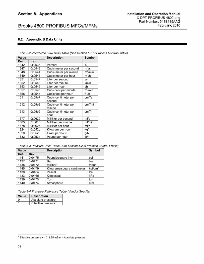
8.2. Appendix B Data Units
Table 8-2 Volumetric Flow Units Table (See Section 5.2 of Process Control Profile)
Value Dec Hex
Description Symbol
1342 0x053e Percent % 1347 0x0543 Cubic meter per second m3/s 1348 0x0544 Cubic meter per minute m3/min 1349 0x0545 Cubic meter per hour m3/h 1351 0x0547 Liter per second l/s 1352 0x0548 Liter per minute l/min 1353 0x0549 Liter per hour l/h 1357 0x054d Cubic foot per minute ft3/min 1358 0x054e Cubic foot per hour ft3/h 1511 0x05e7 Cubic centimeter per
second cm3/s
1512 0x05e8 Cubic centimeter per minute
cm3/min
1513 0x05e9 Cubic centimeter per hour
cm3/h
1577 0x0629 Milliliter per second ml/s 1563 0x061b Milliliter per minute ml/min 1578 0x062a Milliliter per hour ml/h 1324 0x052c Kilogram per hour kg/h 1320 0x0528 Gram per hour g/h 1332 0x0534 Pound per hour lb/h
Table 8-3 Pressure Units Table (See Section 5.2 of Process Control Profile)
Value Dec Hex
Description Symbol
1141 0x0475 Pounds/square inch psi 1137 0x0471 Bar bar 1138 0x0472 Millibar mbar 1145 0x0479 Kilograms/square centimeter kgf/cm2 1130 0x046a Pascal Pa 1133 0x046d Kilopascal kPa 1139 0x0473 Torr torr 1140 0x0474 Atmosphere atm Table 8-4 Pressure Reference Table (Vendor Specific)
Value Description 0 Absolute pressure 1 Effective pressure7
7 Effective pressure + 1013.25 mBar = Absolute pressure

Installation and Operation Manual X-DPT-PROFIBUS-4800-eng Part Number: 541B135AAG February, 2010
39
Section 8. Appendices
Brooks 4800 PROFIBUS MFCs/MFMs
Table 8-5 Temperature Units Table (See Section 5.2 of Process Control Profile)
Value Dec Hex
Description Symbol
1000 0x03e8 Kelvin K 1001 0x03e9 Degrees Celsius oC 1002 0x03ea Degrees Fahrenheit oF
Installation and Operation Manual X-DPT-PROFIBUS-4800-eng Part Number: 541B135AAG February, 2010
Brooks 4800 PROFIBUS MFCs/MFMs LIMITED WARRANTY Seller warrants that the Goods manufactured by Seller will be free from defects in materials or workmanship under normal use and service
and that the Software will execute the programming instructions provided by Seller until the expiration of the earlier of twelve (12) months from
the date of initial installation or eighteen (18) months from the date of shipment by Seller. Products purchased by Seller from a third party for
resale to Buyer (“Resale Products”) shall carry only the warranty extended by the original manufacturer.
All replacements or repairs necessitated by inadequate preventive maintenance, or by normal wear and usage, or by fault of Buyer, or by
unsuitable power sources or by attack or deterioration under unsuitable environmental conditions, or by abuse, accident, alteration, misuse,
improper installation, modification, repair, storage or handling, or any other cause not the fault of Seller are not covered by this limited
warranty, and shall be at Buyer’s expense.
Goods repaired and parts replaced during the warranty period shall be in warranty for the remainder of the original warranty period or ninety
(90) days, whichever is longer. This limited warranty is the only warranty made by Seller and can be amended only in a writing signed by an
authorized representative of Seller.
BROOKS LOCAL AND WORLDWIDE SUPPORT Brooks Instrument provides sales and service facilities around the world, ensuring quick delivery from local stock, timely repairs and local
based sales and service facilities.
Our dedicated flow experts provide consultation and support, assuring successful applications of the Brooks flow measurement and control
products.
Calibration facilities are available in local sales and service offices. The primary standard calibration equipment to calibrate our flow products
is certified by our local Weights and Measures Authorities and traceable to the relevant international standard.
START-UP SERVICE AND IN-SITU CALIBRATION Brooks Instrument can provide start-up service prior to operation when required.
For some process applications, where ISO-9001 Quality Certification is important, it is mandatory to verify and/or (re)calibrate the products
periodically. In many cases this services can be provided under in-situ conditions, and the results will be traceable to the relevant international
quality standard.
CUSTOMER SEMINARS AND TRAINING Brooks Instrument can provide customer seminars and dedicated training to engineers, end users and maintenance persons. Please contact
your nearest sales representative for more details.
HELP DESK In case you need technical assistance,
Americas +(1) 888 554 FLOW
Europe +31 (0) 318 549 290
Asia +81 (0) 3 5633 7100
Due to Brooks Instrument’s commitment to continuous improvement of our products, all specifications are subject to change without notice..
TRADEMARKS Brooks . ................................................................ Brooks Instrument, LLC PROFIBUS..........................................................PROFIBUS International


