1 Supplementary Figure S1. Schematic illustration of the 4 pathways stimulated and sampled by bilateral stimulation of CA3 and bilateral recording in CA1. Whereas the main text (Figures. 2 & 3) focuses solely on the ipsilateral and contralateral pair s1 i and s2 c , data from the opposite, ‘mirror-image’ pair of pathways (s1 c and s2 i ; right-hand side) is presented in Figs. S2, S3, & S5, and Table S1. Although s1 is pictured in the left hemisphere in this figure, left and right hemispheres were randomly designated s1 and s2 in practice.
Transcript
1
Supplementary Figure S1. Schematic illustration of the 4 pathways stimulated
and sampled by bilateral stimulation of CA3 and bilateral recording in CA1.
Whereas the main text (Figures. 2 & 3) focuses solely on the ipsilateral and contralateral pair s1i and s2c,
data from the opposite, ‘mirror-image’ pair of pathways (s1c and s2i; right-hand side) is presented in Figs.
S2, S3, & S5, and Table S1. Although s1 is pictured in the left hemisphere in this figure, left and right
hemispheres were randomly designated s1 and s2 in practice.
2
Supplementary Figure S2. ‘Strong-before-strong’ protocol to obtain s1c and s2i
‘mirror-image’ data. (a) In experiment 1, late-LTP was induced by strong tetanization (arrowheads)
of s1c after aCSF infusion (white rectangle), relative to the untetanized control pathway (s2i) (‘strong +
aCSF’; n = 9). (b) Infusion of anisomycin (black rectangle) blocked late LTP in s1c (‘strong + ANI’; n = 6).
(c) The addition of a strong tetanus to s2i ending 15 min before the start of anisomycin infusion and
tetanization of s1c resulted in late-LTP in both pathways (‘strong-before-strong + ANI’ group, comprising
‘strong + ANI rescued’ and ‘strong rescuer’ pathways; n = 8). Sample fEPSPs recorded in s1c before
(dotted line) and 5 h after tetanization (solid line) are shown (scale bar: vertical = 2 mV; horizontal = 5
ms). (d) Mean fEPSP slope values recorded for s1c and s2i in all experimental groups between 4-5 h after
the relevant tetanus, and normalized to the mean of the 1-h baseline period (*p < 0.05; post-hoc pairwise
comparisons; Fisher’s LSD). An ANOVA of the percentage fEPSP slope LTP 4-5 h after tetanization, with
group (‘strong + aCSF’, ‘strong + ANI’, and ‘strong before strong + ANI’) as a between-subjects factor,
and pathway (s1c and s2i) as a within-subjects factor, did not reveal a significant group x pathway
interaction [F(2,20) = 2.54; p > 0.1]. Similarly, a separate ANOVA of late-LTP in s1c only revealed no main
effect of group [F(2,20) = 2.39; p > 0.1; d, left-hand panel]. However, fEPSP slope values 4-5 h after
tetanization in the ‘strong + ANI’ group did not differ from baseline levels [t(5) = 1.62; p > 0.1; one-sample
t-test], whereas significant potentiation remained in the ‘strong before strong + ANI’ group at this time
point [t(7) = 2.87; p < 0.05; one-sample t-test]. No significant differences were observed in PTP (0-5 min
after the final tetanus train), or early LTP (30-60 min after tetanization) [F < 1 in both cases; ANOVA]. A
separate ANOVA of LTP in s2i revealed a group difference [F(2,20) = 3.48; p = 0.05; d, right-hand panel],
with significant potentiation in the strongly tetanized group, relative to the anisomycin control [p < 0.05;
post-hoc pairwise comparison; Fisher’s LSD], and a trend towards a difference between the aCSF control
and the strongly tetanized group [p = 0.066; post-hoc pairwise comparison; Fisher’s LSD]. Data plotted as
mean ± SEM.
3
Supplementary Figure S3. ‘Weak-before-strong’ protocol to obtain s1c and s2i
‘mirror-image’ data. (a) In experiment 2, strong tetanization (arrowheads) of s1c induced stable late
LTP (‘strong only’; n = 8). (b) Weak tetanization (arrowhead) induced decremental early-LTP that reached
baseline within approximately 3 h (‘weak only’; n = 12). (c) Strong tetanization of s2i 30 min after weak
tetanization of s1c (n = 13) resulted in late-LTP in s2i (‘strong rescuer’), and enhanced, but still decaying,
LTP in s1c (‘weak rescued’). As potentiation tended to be smaller in magnitude in the crossed projection,
it is possible that a slightly stronger ‘weak’ tetanus might be necessary in order to observe a robust
rescue of decaying LTP in this pathway. Sample fEPSPs recorded in s1c before (dotted line) and 5 h after
tetanization (solid line) are shown in a-c (scale bar: vertical = 2mV; horizontal = 5ms). (d) Mean
normalized fEPSP slope in s1c and s2i recorded 4-5 h after tetanization in all groups (*p< 0.05; **p < 0.05;
post-hoc pairwise comparisons; Fisher’s LSD). An ANOVA of the percentage fEPSP slope LTP 4-5 h
after tetanization (Fig. S5d), with group (‘strong only’, ‘weak only’, and ‘weak-before-strong’) as a
between-subjects factor, and pathway (s1c and s2i) as a within-subjects factor, revealed a significant
group x pathway interaction [F(2,31) = 12.4; p < 0.0005]. However, a separate ANOVA of late-LTP in s1c
only revealed no main effect of group [F(2,31) = 1.61; p > 0.2; d, left-hand panel]. In fact, potentiation 4-5
h after tetanization did not differ from baseline in either the weak only [t(11) = 0.26; p > 0.7; one-sample t-
test] or weak-before-strong [t(12) = 1.48; p > 0.1; one-sample t-test] groups. A separate ANOVA of LTP in
s2i revealed a group difference [F(2,31) = 12.3; p = 0.001; d, right-hand panel], with significant
potentiation in the strongly tetanized group, relative to the two control groups [p < 0.001 in both cases;
post-hoc pairwise comparison; Fisher’s LSD]. No significant group differences were observed in PTP (0-5
min after the final tetanus train), or early LTP (30-60 min after tetanization) [F < 1 in both cases; ANOVA].
All data are plotted as mean ± SEM.
4
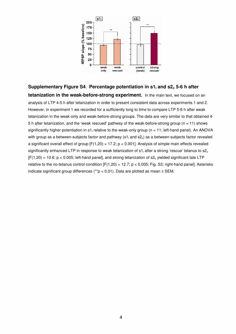
Supplementary Figure S4. Percentage potentiation in s1i and s2c 5-6 h after
tetanization in the weak-before-strong experiment. In the main text, we focused on an
analysis of LTP 4-5 h after tetanization in order to present consistent data across experiments 1 and 2.
However, in experiment 1 we recorded for a sufficiently long to time to compare LTP 5-6 h after weak
tetanization in the weak-only and weak-before-strong groups. The data are very similar to that obtained 4-
5 h after tetanization, and the ‘weak rescued’ pathway of the weak-before-strong group (n = 11) shows
significantly higher potentiation in s1i relative to the weak-only group (n = 11; left-hand panel). An ANOVA
with group as a between-subjects factor and pathway (s1i and s2c) as a between-subjects factor revealed
a significant overall effect of group [F(1,20) = 17.2; p < 0.001]. Analysis of simple main effects revealed
significantly enhanced LTP in response to weak tetanization of s1i after a strong ‘rescue’ tetanus to s2c
[F(1,20) = 10.6; p < 0.005; left-hand panel], and strong tetanization of s2c yielded significant late LTP
relative to the no-tetanus control condition [F(1,20) = 12.7; p < 0.005; Fig. S3; right-hand panel]. Asterisks
indicate significant group differences (**p < 0.01). Data are plotted as mean ± SEM.
5
Supplementary Figure S5. ‘Mirror-image’ electrode placement. Based on the locations
of marking lesions, the positions of stimulating (stars) and recording electrodes (circles) are shown for the
‘mirror-image’ versions of experiments 1 (a) and 2 (b) described above. Numbers indicate distance from
bregma; adapted from Paxinos and Watson, 200560
.
6
Supplementary Table S1. ‘Mirror-image’ baseline parameters. The left-hand panels
show mean baseline fEPSP slope values over the 1-h baseline period in both s2i and s1c for experiments
1 & 2 (the ‘mirror-image’ counterpart to the data presented in Table 1). Stimulation intensities and
percentage paired-pulse facilitation are shown in the right-hand panels. The following analysis is based
on the n numbers indicated in the table. In experiment 1, there were no significant group differences in
baseline fEPSP slope [F < 1], or stimulation intensity [F(2,20) = 1.10; p > 0.3], although baseline fEPSPs
in s2i were significantly larger than those in s1c [F(1,20) = 7.98; p < 0.02], despite the fact that stimulation
intensities did not differ between the 2 pathways [F < 1]; overall, no significant PPF was observed [t(22) =
0.11; p > 0.9; one-sample t-test; comparison to chance = 100%], and no group differences in values were
obtained [F < 1]. In experiment 2, there were no significant group differences in baseline fEPSP slope [F
< 1], or stimulation intensity [F < 1], although baseline fEPSPs in s2i were significantly larger than those in
s1c [F(1,31) = 27.6; p < 0.0005], despite the fact that stimulation intensities did not differ between the 2
pathways [F < 1]. Overall, no significant PPF was observed [t(32) = 0.76; p > 0.4; one-sample t-test;
comparison to chance = 100%], and no group differences in values were obtained [F < 1]. All data are
presented as mean ± SEM.
7
Supplementary Methods
Placement of electrodes
Electrodes were positioned on the basis of characteristic changes in fEPSPs observed as
they were advanced through the hippocampal formation. To illustrate this process,
Figs. 6a & b show examples of the changes in fEPSPs observed in response to ipsilateral
and bilateral stimulation of CA3 respectively, as a recording electrode was lowered into
CA1. The electrode was lowered in 0.1 mm steps, and 3 fEPSPs were recorded at each
depth (pulse width = 50 µs; stimulation intensity = 500 µA). Each data point represents
the mean peak amplitude of the fEPSP. A small negative fEPSP appears in the stratum
oriens / pyramidal cell layer, before reversing and becoming negative as the electrode
enters the stratum radiatum in which the Schaffer collateral / commissural synapses are
located. A similar pattern of changes is observed in response to ipsilateral and
contralateral stimulation. The location of recording and stimulating (see below)
electrode tracks revealed in coronal brain sections taken from the same rat is shown in
Fig. 7c, a stylized representation of the histological section in which the location of the
stimulating electrodes was most evident. (The true location of the recording electrode
track lay approximately 0.3 mm posterior to this point.)
Figs. 6d & e show examples of depth profiles recorded as a stimulating electrode was
lowered ipsilaterally (d) or contralaterally (e) relative to a stationary recording electrode
in the stratum radiatum. Note that a negative-going response is first obtained by
stimulation of CA1, then disappears, before re-emerging when the electrode reaches
CA3. The sample fEPSPs presented illustrate the increase in response latency observed
as an ipsilateral stimulator moves from CA1 to CA3, reflecting an increase in the
distance over which action potentials must travel in the latter case. Conversely,
contralateral fEPSPs exhibit a decrease in latency as the electrode is moved from CA1 to
CA3. The explanation for this change lies in the fact that stimulation of CA1
contralateral to the recording electrode causes a potentially bilateral antidromic
8
activation of CA3, followed by orthodromic activation of CA1 ipsilateral to the
recording electrode. This configuration does not yield independent ipsilateral and
contralateral inputs to CA1 (see Fig. 1d, left-hand bar). However, stimulation of
contralateral CA3 results in the direct activation of crossed commissural fibers, hence
the reduction in fEPSP latency. Although antidromic activation of crossed CA3-CA3
afferents, followed by orthodromic activation of collaterals innervating CA1, is also
likely to occur when CA3 is stimulated, paired-pulse facilitation data confirm that
bilateral CA3 stimulation activates independent populations of ipsilateral and
contralateral afferents to the neurons sampled by each recording electrode (Fig. 1d,
middle bar).
Rescue of LTP in the contralateral projection (s1c) by strong tetanization of the
ipsilateral projection (s2i)
In the main text, we focus solely on the rescue of decaying potentiation in the ipsilateral
CA3-CA1 projection (s1i) by strong tetanization of the contralateral crossed CA3-CA1
pathway (s2c). However, a unilateral tetanus potentiates both ipsilateral and
contralateral CA3-CA1 pathways, and an analysis of the opposite, mirror-image
situation is also possible—in other words rescue of LTP in the crossed CA3-CA1
projection (s1c) originating from the same stimulation site as s1i, by strong tetanization
of the ipsilateral CA3-CA1 pathway (s2i) originating from the same stimulation site as
s2c. Fig. S2 below illustrates, in schematic form, all 4 possible pathways stimulated and
sampled in response to bilateral placement of CA3 stimulating electrodes and CA1
recording electrodes. Crossed CA3-CA3 projections are omitted from the figure.
In experiments 1 and 2, both pairs of ipsilateral and contralateral pathways (i.e. 4
pathways in total) met our criteria for initial fEPSP size and subsequent stability in
many rats (n = 42). However, in some cases, only one pair met these criteria. The n of 51
(experiment 1 = 22; experiment 2 = 29) reported in the main analysis therefore
represents data from 42 animals in which all 4 CA3-CA1 pathways were collected, and
9
9 animals in which only the s1i and s2c pair provided data. In 15 animals, however, only
the s2i and s1c pair yielded useful data; together with the 42 rats in which all pathways
were acceptable, this results in a total of 57 rats in which s2i and s1c data were available,
23 in experiment 1 and 34 in experiment 2. Data from these pathways is shown in Figs.
S2 & S3, and the ‘mirror-image’ electrode locations are shown in Fig. S5.
Following the paired-pulse stimulation procedure outlined in the main text (see
Methods), the procedure was repeated in the opposite order (s1 followed by s2) to test
the independence of the ‘mirror-image’ pair of pathways, s1c and s2i (see Table S1).