1
Supplementary Information
Anodization driven synthesis of nickel oxalate nanostructures
with excellent performance for asymmetric supercapacitors†
Guanhua Cheng,§a Junling Xu,§b Chaoqun Dong,a Wanfeng Yang,a Tianyi Kou,a
Zhonghua Zhang, *a
a Key Laboratory for Liquid-Solid Structure Evolution and Processing of Materials
(Ministry of Education), School of Materials Science and Engineering, Shandong
University, Jingshi Road 17923, Jinan 250061, P.R. China. Email:
[email protected]; Fax: +86 0531-88396978; Tel: +86 0531-88396978b Department of Electronic Engineering, The Chinese University of Hong Kong, New
Territories, Hong Kong, P.R. China
§The authors equally contribute to this work.
Synthesis of NON@NF electrode materials
The nanostructured nickel oxalate material was synthesized by an in-situ
electrochemical method (anodization). Commercial nickel foam was degreased by
sonicating in acetone, then rinsed with deionized water and dried in air. A two-
electrode electrochemical cell with a nickel foil cathode was used to fabricate
nanostructured nickel oxalate. Nickel foam was cut into pieces and sealed to ensure
the working area was 2 cm×2 cm or 5 cm×5 cm. The nickel foam was used as the
anode. Anodization was performed in a 0.3 M oxalic acid aqueous solution at a
constant voltage of 50 V and controlled temperature of -5 oC for 10 min, using a DC
stabilized power supply (Wenhua, China). After the reaction, the as-obtained samples
were rinsed with deionized water and anhydrous alcohol. Thus the NON@NF
electrode was prepared through the facile efficient anodization method. It should be
Electronic Supplementary Material (ESI) for Journal of Materials Chemistry A.This journal is © The Royal Society of Chemistry 2014
2
noted that this anodization route could be easily scaled up, which is crucial for
practical applications of such electrode materials for supercapacitors.
Microstructural and electrochemical characterization of NON@NF electrode
The microstructure of the as-obtained samples were characterized by X-ray
diffraction (XRD, RigakuD/max-rB) with Cu Kα radiation, scanning electron
microscopy (SEM, LEO 1530 VP) and transmission electron microscopy (TEM, FEI
Tecnai G2). Selected-area electron diffraction (SAED) was also performed to
document the crystalline nature of the samples. TEM specimens were prepared by ion
milling at 5 kV (Gatan ion mill).
Electrochemical measurements including cyclic voltammetry (CV) and
galvanostatic charge-discharge of the NON@NF electrode were performed using a
potentiostat (CHI660E, Shanghai, Chenhua) in a cell with a three electrode
configuration. The bright Pt foil was used as the counter electrode and an Ag/AgCl
electrode (in saturated KCl solution) was used as the reference electrode. The
electrolyte was a 6 M KOH aqueous solution which was prepared from analytical-
grade KOH and pure deionized water (18.25 mΩ∙cm). The stability of the electrode
was evaluated through CV measurements at a scan rate of 50 mV s-1. All
measurements were performed at room temperature.
Assembly and electrochemical measurements of NON@NF//AC asymmetric
supercapacitor
An asymmetric supercapacitor was assembled using the NON@NF as the positive
electrode and an activated carbon (AC) electrode as the negative electrode. The
cellulose paper was used as the separator. The electrolyte was the 6 M KOH aqueous
solution. The AC electrode was prepared as follows. Firstly, AC (TF-B520) was
mixed with TIMCAL SUPER C45 conductive carbon black and polyvinlidene
fluoride (PVDF), and their mass ratio was 8:1:1. Appropriate N-methyl pyrrolidone
(NMP) was added into the mixture as a solvent to make a slurry which was coated
3
onto a nickel foam (2 cm×2 cm or 5 cm×5 cm). Finally, the as-prepared electrode
was dried at 80 oC for 5 h to remove the solvent.
It is well known that the charge balance between the two electrodes should follow
the relationship q+ = q- so that to obtain a good electrochemical performance.S1 The
charge stored by each electrode usually depends on the specific capacitance C (F g-1),
the voltage range ∆V (V) and the mass of the electroactive material m (g), and the
related equation is given as follows:S2
(1)𝑞 = 𝐶 × ∆𝑉 × 𝑚
In order to obtain q+ = q-, the mass balance will be expressed as follows:S2
𝑚 +
𝑚 ‒=
𝐶 ‒ × ∆𝑉 ‒
𝐶 + × ∆𝑉 +
(2)
Where ‘+’ and ‘-’ denote the positive and negative electrode respectively.
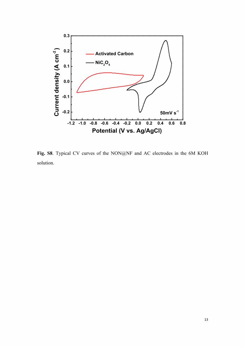
To determine the mass ratio of our NON@NF//AC asymmetric supercapacitor,
typical CV curves were obtained for the NON@NF electrode and AC electrode at a
scan rate of 50 mV s-1 in the 6 M KOH aqueous solution (Fig. S7). The specific
capacitance of the NON@NF electrode was calculated as 409.5 F g-1. The specific
capacitance of the AC electrode was 78.4 F g-1. Based on the specific capacitance
values and the potential windows of the two electrodes, the optimal mass ratio of
m+(nickel oxalate)/m-(AC) was determined to ~0.29 in the NON@NF//AC
asymmetric supercapacitor.
Electrochemical measurements of the NON@NF//AC asymmetric supercapacitor
were also carried out using the CHI 660E potentiostat, including cyclic voltammetry,
galvanostatic charge/discharge and electrochemical impedance spectroscopy (EIS).
EIS was performed in a frequency range from 0.01 Hz to 100 kHz with a 5 mV
amplitude at open circuit potential. Energy density and power density of the
supercapacitor were calculated based on the galvanostatic discharging profiles, based
4
upon the total mass of both the positive and negative active materials. The cycling
performance of the supercapacitor was evaluated using the galvanostatic
charge/discharge cycling between 0 and 1.7 V at a current density of 1 A g-1.
Calculation
Through DSC and XRD, we have confirmed that the water of crystallization could
be removed from the as-anodized nickel oxalate through annealing in air at 280 oC.
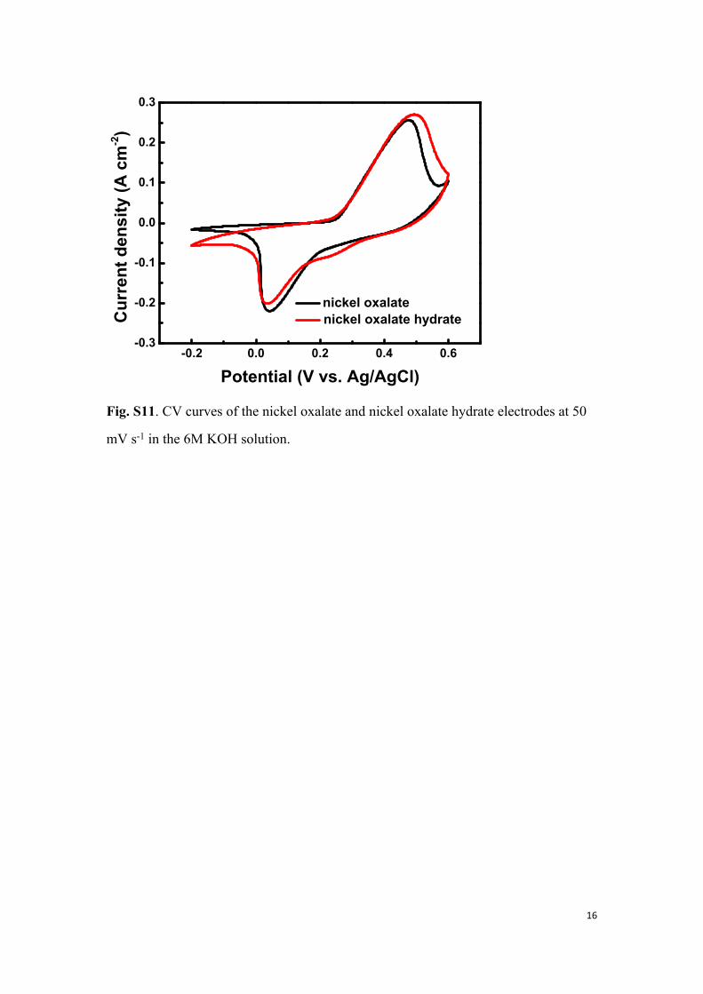
We have done a comparative trial on both the as-anodized (with water of
crystallization) and as-annealed (without water of crystallization) samples. The
overlapped CV curves of the electrodes (as-anodized and as-annealed) are shown in
Fig. S11. The almost equal capacitance calculated from the CV curves indicates that
the water of crystallization has little influence on the electrochemical properties in the
aqueous solution. Thus the as-anodized samples were directly used the electrodes
without further treatment in our work.
The calculation principle about the mass of active nickel oxalate was mainly based
on the phase changes during the course of thermal annealing. According to the TG-
DSC results, there are two weight loss steps in the temperature ranges of 180-280 oC
and 280-380 oC, corresponding to the loss of crystallization water in nickel oxalate
hydrate and the transformation from nickel oxalate to nickel oxide respectively (both
have been confirmed by XRD). The weight change during annealing is owing to the
phase transformation from NiC2O4∙2H2O to NiO. Based upon the phase
transformations we could calculate the weight loss during different steps of annealing,
which is in accordance with the TG results. And therefore we could also obtain the
mass of the nickel oxalate on the nickel foam.
In addition, we prepared tens of anodized nickel foams (2*2 cm2), labeled and
weighted respectively. Thus all samples were annealed at 400 oC. Then we weighted
the samples again, obtained the weight loss of each sample and averaged them. These
results are also well consistent with the TG analysis.
The specific capacitance of the electrode could be calculated from the CV curves
5
according to the following equation:S3
(4)𝐶 = (∫I d V) / (𝑣𝑚∆𝑉)
Where C is the specific capacitance (F g-1) based on the mass of the electroactive
material (NiC2O4), I is the response current (A), V is the applied potential, ∆V is the
potential window (V), ν is the potential scan rate (mV s-1), and m is the mass of the
electroactive material on the electrode (g).
The specific capacitance can also be calculated from the galvanostatic
charge/discharge profiles by the following formula:S4
(5)𝐶 = 𝐼∆𝑡 𝑚∆𝑉
Where I is the discharge current (A) and ∆t is the discharge time (s).
The specific capacitance (C), energy density (E) and power density (P) of the
NON@NF//AC asymmetric supercapacitor were calculated using the following
equations:S4
(6)𝐶 = 𝐼∆𝑡 𝑚∆𝑉
(7)𝐸 = 0.5𝐶∆𝑉2
(8)𝑃 =
𝐸∆𝑡
Where m is the total mass of the electroactive materials (NiC2O4 and AC) of the
supercapacitor.
Supplementary Figures (Fig. S1-S11)
Supplementary Videos (Video S1-S3)
6
Fig. S1. Low-magnification SEM image of the nickel foam coated with nickel oxalate
nanostructures, showing its instinct 3D network.
7
b
a
Fig. S2. SEM images of the anodized nickel foam (NON@NF). Some nickel oxalate
blocks gather together to form clusters, there exist channels or cracks between clusters.
One cluster is highlighted by solid red circles.
8
Fig. S3. High-magnification TEM image of the NON@NF electrode, clearly showing
that nickel oxalate hydrate in-situ grew on the skeleton surface of nickel foam.
9
0 20 40 60 80 100
(0
22) (2
20)
(200
)
(111
)
(400
)
(004
)Inte
nsity
(a.u
.)
2(degree)
NiC2O42H2ONi
(202
)
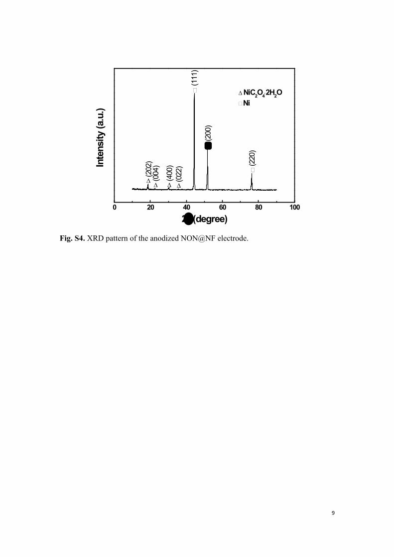
Fig. S4. XRD pattern of the anodized NON@NF electrode.
10
-0.2 0.0 0.2 0.4 0.6
-0.3
-0.2
-0.1
0.0
0.1
0.2
0.3
0.4
Cur
rent
den
sity
(A c
m-2)
Potential (V vs. Ag/AgCl)
NON@NF Nickel Foam
100 mV s-1
Fig. S5. Typical CV curves of the NON@NF and nickel foam electrodes at 100 mV s-
1 in the 6M KOH solution.
11
-0.2 0.0 0.2 0.4 0.6
-0.2
-0.1
0.0
0.1
0.2
0.3
Curr
ent d
ensi
ty (A
cm
-2)
Potential (V vs. Ag/AgCl)
a
1st ~ 100th cycles
-0.2 0.0 0.2 0.4 0.6
-0.2
-0.1
0.0
0.1
0.2
0.3
Curr
ent d
ensi
ty (A
cm
-2)
Potential (V vs. Ag/AgCl)
b
4950th ~ 5050th cycles
-0.2 0.0 0.2 0.4 0.6
-0.2
-0.1
0.0
0.1
0.2
0.3
Curr
ent d
ensi
ty (A
cm
-2)
Potential (V vs. Ag/AgCl)
c
9900th ~ 10000thcycles
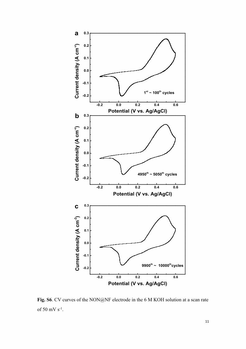
Fig. S6. CV curves of the NON@NF electrode in the 6 M KOH solution at a scan rate
of 50 mV s-1.
12
c
b
a
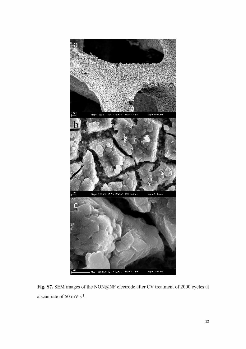
Fig. S7. SEM images of the NON@NF electrode after CV treatment of 2000 cycles at
a scan rate of 50 mV s-1.
13
-1.2 -1.0 -0.8 -0.6 -0.4 -0.2 0.0 0.2 0.4 0.6 0.8
-0.2
-0.1
0.0
0.1
0.2
0.3
Activated Carbon
NiC2O4
Cur
rent
den
sity
(A c
m-2
)
Potential (V vs. Ag/AgCl)
50mV s-1
Fig. S8. Typical CV curves of the NON@NF and AC electrodes in the 6M KOH
solution.
14
0 500 1000 1500 2000 2500 3000 35000
5
10
15
20
25
30
35
40
this work ref. S5 ref. S6 ref. S7 ref. S8
Ener
gy d
ensi
ty (W
h kg
-1)
Power density (W kg-1)
Fig. S9. Ragone plot related to energy and power densities of the NON@NF//AC
asymmetric supercapacitor compared with other data reported in the literature [S5-S8].
15
b
e f
a
dc
Fig. S10. Photographs of the NON@NF//AC asymmetric supercapacitor and the
devices used in the demonstration experiments. (a) Photograph of the NON@NF (left)
and AC (right) electrodes (5 cm×5 cm). (b) Photograph of a NON@NF//AC
asymmetric supercapacitor. (c) Photograph of a series of NON@NF//AC asymmetric
supercapacitors. (d) Photograph showing the connection between the supercapacitors
and the mobile phone where the battery was removed. (e) Photograph of the‘CHINA’
LED displayer which is composed of 48 LEDs. (f) Photograph of the ‘SDU’ LED
displayer which is composed of 32 LEDs.
16
-0.2 0.0 0.2 0.4 0.6-0.3
-0.2
-0.1
0.0
0.1
0.2
0.3
Cur
rent
den
sity
(A c
m-2)
Potential (V vs. Ag/AgCl)
nickel oxalate nickel oxalate hydrate
Fig. S11. CV curves of the nickel oxalate and nickel oxalate hydrate electrodes at 50
mV s-1 in the 6M KOH solution.
17
Supplementary Videos:
Video S1: Video showing that three supercapacitors can power a mobile phone,
including its starting up and running for several minutes.
Video S2: Video showing that five supercapacitors in series can light up a ‘CHINA’
LED displayer.
Video S3: Video showing that four supercapacitors in series can light up a ‘SDU’
LED displayer.
Supporting References:
S1 H. B. Li, M. H. Yu, F. X. Wang, P. Liu, Y. Liang, J. Xiao, C. X. Wang, Y. X.
Tong and G. W. Yang, Nat. Commun., 2013, 4, 1894.
S2 V. Khomenko, E. Raymundo-Piñero and F. Béguin, J. Power Sources, 2006, 153,
183-190.
S3 P. Simon and Y. Gogotsi, Nat. Mater., 2008, 7, 845-854.
S4 Q. Lu, M. W. Lattanzi, Y. Chen, X. Kou, W. Li, X. Fan, K. M. Unruh, J. G. Chen
and J. Q. Xiao, Angew. Chem., 2011, 123, 6979-6982.
S5 X. Wang, A. Sumboja, M. Lin, J. Yan and P. S. Lee, Nanoscale, 2012, 4, 7266-
7272.
S6 H. Wang, Y. Liang, T. Mirfakhrai, Z. Chen, H. Casalongue and H. Dai, Nano Res.
2011, 4, 729-736.
S7 X. Yu, B. Lu and Z. Xu, Adv Mater, 2014, 26, 1044-1051.
S8 X. Wang, W. S. Liu, X. Lu and P. S. Lee, J. Mater. Chem., 2012, 22, 23114-
23119.


![Reduction of Oxalate Levels in Tomato Fruit and … of Oxalate Levels in Tomato Fruit and Consequent Metabolic Remodeling Following Overexpression of a Fungal Oxalate Decarboxylase1[W]](https://static.documents.pub/doc/80x56/5af8e5787f8b9aff288c704b/reduction-of-oxalate-levels-in-tomato-fruit-and-of-oxalate-levels-in-tomato.jpg)


