Page 1
FINAL
Surface Treatment Plan
Valley South Subtransmission Project
Prepared for
Southern California Edison
September 17, 2018
Prepared By
29970 Technology Drive, Ste 215
Murrieta, CA 92563
Mitigation Measures Covered:
MM AES-6: Treat Structure Surfaces
Page 2
Valley South Subtransmission Project Surface Treatment Plan Page ii
Contents
List of Acronyms ..................................................................................................................... iii
Introduction.......................................................................................... 1-1
1.1 Project Overview .................................................................................................................. 1-1
1.2 Lead Agencies ..................................................................................................................... 1-1
1.3 Mitigation Measures ............................................................................................................. 1-1
1.4 Applicable Project Areas ..................................................................................................... 1-2
Methods ................................................................................................ 2-1
2.1 Subtransmission and Distribution ........................................................................................ 2-1
2.2 Telecommunication Equipment ........................................................................................... 2-1
2.3 Maintenance of Surface Treatment ..................................................................................... 2-2
Plan Approval ...................................................................................... 3-1
References ........................................................................................... 4-1
APPENDIX A Manufacturer Specifications .............................................................. A-1
List of Figures
Figure 1 Project Overview Map
Figure 2-1 Surface Finish Comparison
Figure 2-2 Simulated View of Tubular Steel Structures
Page 3
Valley South Subtransmission Project Surface Treatment Plan Page iii
List of Acronyms
CEQA California Environmental Quality Act
CPUC California Public Utilities Commission
FEIR Final Environmental Impact Report
kV Kilovolt
LWS Lightweight Steel
MM Mitigation Measure
MMP Mitigation Monitoring Plan
MPR Minor Project Refinement
PTC Permit to Construct
SCE Southern California Edison
TSP Tubular Steel Pole
VSSP Valley South Subtransmission Project
ROW Right-of-Way
Page 4
Introduction
Valley South Subtransmission Project Surface Treatment Plan Page 1
INTRODUCTION
This Surface Treatment Plan (Plan) for Southern California Edison’s (SCE) Valley South Subtransmission
Project (VSSP or Project) identifies compliance activities that will support Mitigation Measure (MM) AES-6
from Appendix 6, the Mitigation Monitoring Plan (MMP) of the Project’s Final Environmental Impact Report
(FEIR). This Plan is written in compliance with the guidance provided by the California Public Utilities
Commission (CPUC) Permit to Construct (PTC), and in compliance with the impacts analyzed in the FEIR.
This Plan has been developed to facilitate compliance with the measures listed in Table 6-1 of the MMP; and
when implemented, will reduce potential reflectance and contrast with the existing landscape.
1.1 Project Overview
Wilson Utility Construction Company (Wilson) has been contracted by SCE to perform the engineering,
environmental compliance, property acquisition, material procurement, and construction of the Valley South
Subtransmission Project. The Project includes construction of a new 115-kilovolt (kV) subtransmission line
approximately 15.4 miles in length from Valley Substation in the City of Menifee to just west of Triton
Substation in the City of Temecula.
Segment 1 consists of the construction of approximately 12 miles of new 115kV subtransmission line from
Valley Substation, including the associated wood and steel poles and relocation of distribution and
telecommunication facilities along the corridor to a tubular steel pole (TSP) at the intersection of Leon and
Benton Road. Additionally, Segment 1 includes two sections of 115kV underground trenching and conduit
installation within Riverside County. Segment 2 consists of the replacement of 3.4 miles of existing 115kV
subtransmission line conductor from the intersection of Leon and Benton road to the existing terminal TSP on
the south side of Nicolas Road near Triton Substation.
VSSP work activities performed by SCE or others includes equipping an existing 115kV line position and
providing protection equipment as required at Valley Substation; installation of telecommunications equipment
at Triton and Valley substations to connect the Project to SCE’s existing telecommunication system; and, the
installation of the 115kV underground cable and connections.
1.2 Lead Agencies
Lead agencies have discretionary approval over VSSP and are responsible for reviewing aspects of the
measures documented in this Plan.
The CPUC is the state lead agency responsible for compliance with the California Environmental
Quality Act (CEQA).
1.3 Mitigation Measures
This Plan addresses MM AES-6 from the FEIR that states:
Treat Structure Surfaces. SCE shall treat the surfaces of all structures visible to the public such that: a)
their colors minimize visual contrast by blending with the characteristic landscape colors; and b) their
colors and finishes do not create excessive glare. SCE should consult with applicable city and county
agencies regarding the colors and finishes used on project structures. The subtransmission facilities
and conductors shall be non-specular and non-reflective, and the insulators shall be non-reflective and
non- refractive (SCE has stated in their project description that they will use non-specular 954 SAC
Page 5
Introduction
Valley South Subtransmission Project Surface Treatment Plan Page 2
conductors). SCE shall use appropriate colors that blend effectively with the surrounding land-scape.
SCE has stated in their project description that the TSPs will have a “dulled galvanized finish.”
SCE shall provide to the CPUC for review, a Surface Treatment Plan describing the materials and dulling
treatment proposed along with samples of treated material. The plan shall also describe the application
of any post-manufacture colors and textures to new facility structures and explain how the overall Project
design will reduce glare and minimize visual intrusion and contrast by blending the facilities with the
landscape. The plan shall be submitted to CPUC at least 60 days prior to ordering the first structures that
are to be color-treated during manufacture or prior to construction of any of the facility components,
whichever comes first. If the CPUC notifies SCE that revisions to the plan are needed before the plan can
be approved, within 30 days of receiving that notification, SCE shall prepare and submit for review and
approval a revised plan. The Surface Treatment Plan shall include the following components and
specifications.
Specification, and 11” x 17” color simulations at life-size scale, of the treatment proposed for
use on structures, including structures treated during manufacture.
A list of each major structure and/or pole specifying the color(s) and finish(es) proposed for
each (colors must be identified by name and by vendor brand or a universal designation).
Two sets of brochures and/or color chips for each proposed color.
A detailed schedule for completion of the treatment
A procedure to ensure proper treatment maintenance for the life of the Project.
Until SCE receives notification of the approval of the Surface Treatment Plan by the CPUC,
SCE shall not specify to the vendors the treatment of structures for manufacture and shall
not perform the final treatment on structures treated on site. Additionally, construction
activities shall not start until approval of the plan from the CPUC has been received. Within
14 days following the completion of treatment on any facility component, SCE shall notify
the CPUC that the component (e.g., structure) is ready for inspection.
1.4 Applicable Project Areas
This Plan addresses structure surface treatment procedures required for all facilities constructed across all
Segments of the Project.
Refer to Figure 1 on the following page.
Page 6
Introduction
Valley South Subtransmission Project Surface Treatment Plan Page 3
Figure 1 Project Overview Map
Page 7
Methods
Valley South Subtransmission Project Surface Treatment Plan Page 1
METHODS
The following sections include a description of the methods by which SCE will treat the surfaces of structures
visible to the public to minimize visual contrast and excessive glare. This Project includes upgrading existing
subtransmission, distribution, and telecom facilities. Project components on which new facilities will be
constructed are limited to replacement of subtransmission, distribution, and telecommunication lines and
structures. New structures are planned to be a combination of wood poles, light weight steel poles (LWS),
and tubular steel poles (TSP). No new substations, reactors, series capacitors, or other facilities that would
introduce potential visual contrasts have been proposed.
2.1 Subtransmission and Distribution
MM AES-6 specifies that the subtransmission facilities and conductors shall be non-specular and non-
reflective, and the insulators shall be non-reflective and non-refractive. The FEIR’s project description states
that non-specular 954 SAC conductors will be used and that the TSPs will have a dulled galvanized finish.
The subtransmission and distribution project components may include TSPs, lightweight steel (LWS) poles
and wooden poles. Wooden poles are, by nature, non-reflective and do not contrast with the surrounding
landscape.
Wilson considered two finish treatments (light gray dulled galvanized, and light gray non-dulled galvanized)
for the subtransmission and distribution project components. The goal was to select a surface treatment that
would blend into the landscape settings. In viewing the galvanized TSPs along recently built transmission
lines in Southern California, it was apparent that the non-dulled galvanized structures would reflect the sun,
stand out against the existing landscape, and provide more contrast than light gray dulled galvanized poles,
which tend to blend into the background with distance. For this reason, Wilson determined that the best
choice for blending the proposed structures into the Project landscape is the light gray dulled galvanized steel
for the TSPs and LWS poles. These poles will be treated at the factory to produce a dulled light gray surface
that minimizes contrast. Manufacturers’ specifications for the galvanizing and dulling process are included in
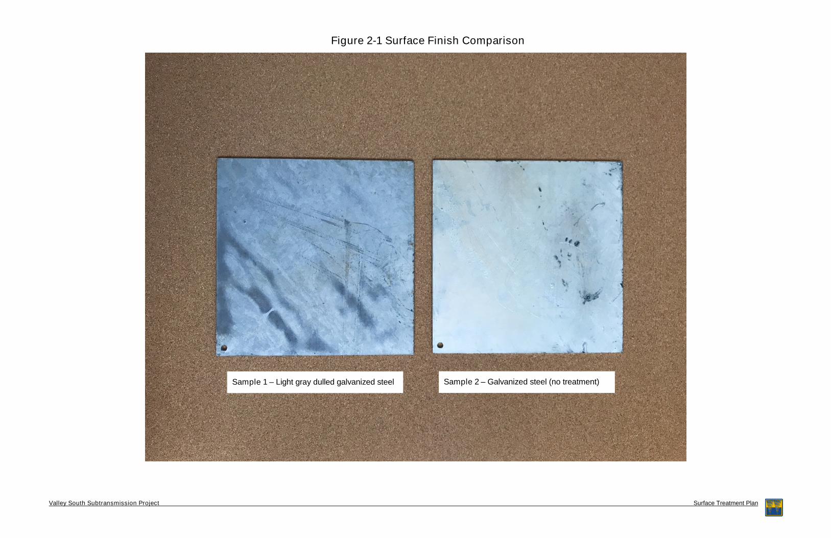
Appendix A. Figure 2-1 depicts a color sample comparison steel plate for each of the two treatments
considered. Sample 1 represents the dulling and light gray galvanized color that will be specified for the steel
used for the Project structures. Sample 2 represents a plate of galvanized steel that has not received any
dulling or darkening.
For all segments of the Project, the FEIR specified the use of non-specular conductors, and composite
insulators with a dulled gray finish. In addition to the conductor materials, the insulators specified will be made
of a polymer material with a dulled gray finish that will not have the reflective or refractive properties associated
with glass insulators. Figure 2-2 depicts a simulation of a segment of the line with TSPs with the light gray
dulled galvanized treatment, non-specular conductor, and polymer insulators with a dulled gray finish.
2.2 Telecommunication Equipment
The Project includes relocation of telecommunication lines and equipment for the protection, monitoring, and
control of the subtransmission lines and substation equipment. Most of the new telecommunication equipment
will be located inside existing substations on the existing telecommunication sites and will not be visible. The
telecommunication lines will be thin, black insulated wires with low levels of visibility. The splice boxes that
will be located on the structures that carry the telecommunication lines will be smaller and similar to American
National Standards Institute 70 gray in color. Because these boxes are small and will have a dull, neutral-
colored finish, no further surface treatment will be required.
Page 8
Methods
Valley South Subtransmission Project Surface Treatment Plan Page 2
2.3 Maintenance of Surface Treatment
The structure steel, insulators, and conductors are expected to further dull over time and show less visual
contrast. Maintenance is not expected to be required for these components to maintain a dull finish throughout
the lifespan of the structure.
If a minor scratch or rub on Project steel poles occurs during construction, post-manufacture applications of
chemical treatments (such as galvanizing spray) of the appropriate color, or cold galvanizing will be used to
ensure structures blend effectively with the surrounding landscape.
Page 9
Plan Approval
Valley South Subtransmission Project Surface Treatment Plan Page 1
PLAN APPROVAL
This Plan has been prepared to address MM AES-6. SCE requests review and approval of this Plan from the
CPUC. If necessary, the Plan may be amended to reflect any information contained within subsequent
clearance and approval documents.
Page 10
References
Valley South Subtransmission Project Surface Treatment Plan Page 1
REFERENCES
California Public Utilities Commission. “Final Environmental Impact Report.” Southern California Edison
Valley South Subtransmission Project. (June 2016)
http://www.cpuc.ca.gov/environment/info/aspen/valleysouth/Index_6_9_16.htm.
Page 12
Valley South Subtransmission Project Surface Treatment Plan
Figure 2-1 Surface Finish Comparison
Sample 1 – Light gray dulled galvanized steel Sample 2 – Galvanized steel (no treatment)
Page 13
Valley South Subtransmission Project Surface Treatment Plan
Figure 2-2 Simulated View of Tubular Steel Structures
Simulated view depicting a light gray dulled galvanized TSP at intersection of Leon Rd. and Benton Rd. (Left: Existing conditions, Right: Simulation of new proposed TSP)
Page 14
Valley South Subtransmission Project Surface Treatment Plan Page 1
Manufacturer Specifications
F-001 Galvanized Product ASTM A-123 REV 10
Page 15
Valley South Subtransmission Project Surface Treatment Plan Page 2
F-113 Chemical Deglare Process Rev 11