+ All Categories
Home > Documents > 'Surry Power Station Disposal of Low Level Radioactively ... · clay. This clay liner was designed...

'Surry Power Station Disposal of Low Level Radioactively ... · clay. This clay liner was designed...

Date post: 21-Apr-2020
Category:
Upload: others
View: 3 times
Download: 0 times
Share this document with a friend
28
SURRY POWER STATION DISPOSAL OF LOW-LEVEL RADIOACTIVELY CONTAMINATED SOIL IN THE DREDGE SPOILS POND Prepared by: Reviewed by: Approved by: C. A. Tarantino Staff, Health Physics F. L. Thomasson Supervisor, Health Physics wvv;~~ W. W~Cameron Director, Health Physics
Transcript

SURRY POWER STATION

DISPOSAL OF LOW-LEVEL RADIOACTIVELY

CONTAMINATED SOIL IN THE

DREDGE SPOILS POND

Prepared by:

Reviewed by:

Approved by:

~t2~~ C. A. Tarantino

Staff, Health Physics

F. L. Thomasson Supervisor, Health Physics

wvv;~~ W. W~Cameron Director, Health Physics

A.

B.

c.

D.

E.

F.

G.

H.

I.

e TABLE OF CONTENTS

Section

Introduction ••••••••••. e e e e e e e e O e e e e e e • e • Cl e e e e e • e e

Description of Contaminated Soil and Gravel •••

Page No.

. ..... 1

• • 2

Description of Dredge Spoils Pond ••••••••••••••••••••••.•••••••• 4

Site Area Characteristics ••••••••.••••••••••••••••••••.••••••••• 5

Meteorology •••• .5

Hydrology •••••• .6

Geology . ..... o ••••••••••• ii •••••••••• ., •••••••••••••••••••••• 7

Alternative Disposal Methods .................... ., ............... 7

Burial of Contaminated Soil ••••••••••••••••..•••••••••••••• 7

Shipment to Licensed Disposal Facility •••••••••••••••••.••• 8

Disposal of Contaminated Soil in the Dredge Spoils Pond ••••••••• 8

Radiological Assessment ••••• • •••••• 9

Conclusion ........... o ••••••••••••••••••• o •••••••••••••••••••• • 12

References . ....... Cl ••••••••••••••••••••••••••••••••••••••• o ••• • 12

Attachment 1 - Diagrams of Dredge Spoils Pond

Attachment 2 - Radiological Assessment Calculations

DISPOSAL OF LOW-LEVEL RADIOACTIVELY CONTAMINATED SOIL AND

GRAVEL IN THE ON-SITE DREDGE SPOILS POND AT SURRY POWER STATION

A. INTRODUCTION

Surry Power Station is planning to pave the yard area within the pro­

tected area, i.e., the area inside the security fence. Over the years,

the grades inside the fence have been raised as a result of roadway

repairs and the disposal of excess soil. Pavement construction would

require the excavation of large quantities of soil from various con-

struction projects. In some locations within the Radiological Control

Area (RCA) the soil is low-level radioactively contaminated from previous

steam releases and radioactive liquid spills.

A preliminary engineering study was conducted to determine the required

pavement sections for the yard areas based upon actual onsite soil

conditions, to estimate quantities of materials that must be excavated in

order to construct the pavement, and to investigate options for final

disposal of the excavated material outside of the protected area. The

study concluded that approximately 6,000 cubic yards of contaminated soil

and gravel would require disposal. In addition, the study recommended

that the 6,000 cubic yards figure be increased to 10,000 cubic yards to

incorporate future construction activities. The contaminated soil and

gravel would be disposed in the dredge spoils pond which is located on

Virginia Electric and Power Company's owner controlled property.

45/1/LLR/CAT - 1 -

i

' e B. DESCRIPTION OF CONTAMINATED SOIL AND GRAVEL

Four test pits were excavated in order ,to define sub-grade conditions for

pavement design. The following is a brief description of the materials

that were encountered:

Stratum I All pits except one encountered approximately 5 to 6. 5

inches of dense graded crushed stone at the ground surface. Visually

this material is similar to normal aggregate utilized for roadway bases

and sub-bases.

Stratum II A layer of old asphalt was encountered at three locations.

The asphalt was only 1 to 2 inches thick and generally was observed below

the crushed aggregate.

Stratum III All pits encountered dense to very dense reddish brown

sandy gravel either below the crushed stone or the asphalt. This

material is a portion of the select granular backfill material that was

used to fill the original plant excavation back to grade. A majority of

the reactor containment area was excavated from an original grade of 34

feet to elevation 7 feet during construction. After completion of the

major structures, the area was back-filled to plant design grade of 26.5

feet. The sandy gravel extended to variable depths of 18 to 36 inches

below existing grade.

Stratum IV Below the dense gravel, all excavations, except one

outside the Administration Building, encountered dense tan silty sand

with some fine gravel. This material was also part of the select back­

fill for the general plant excavation.

45/1/LLR/CAT - 2 -

/ ' \.

e Stratum V One test pit and the excavation outside the Administration

Building encountered stiff tan and gray silty clay immediately beneath

Stratum III gravel. This material is a natural deposit occurring at the

surface of the plant site. The above locations fall either outside or on

the edge of the area that was excavated to elevation 7 feet, This

explains why natural soil deposits were encountered at such a shallow

depth.

An extensive sampling program was performed to determine the identity of

the contaminating radionuclides and their concentrations in the soil and

gravel. Fifty-seven (57) sampling locations were identified in the yard.

Locations were representative of those areas in which paving activities

would generate soil and gravel requiring disposal. Surface, 6 inch and

12 inch samples were obtained and analyzed for each location for a total

of 171 samples. Sample results were averaged to determine the following

concentrations (µCi/gm):

RADIONUCLIDE

Co-60

Cs-134

Cs-137

Mn-54

AVERAGE CONCENTRATION (µCi/gm)

1.56E-06

5.26E-07

2.38E-06

2.68E-09

These isotopic concentrations were used to perform the radiological dose

assessments.

45/1/LLR/CAT - 3 -

C. DESCRIPTION OF DREDGE SPOILS POND

2.

Diagrams showing the dredge spoils area are provided in Attachment 1 for

your reference.

1. The dredge spoils pond is located adjacent to the low-level intake

structure, east of the plant. The pond is approximately 2,700 feet

long and 600 to 1,300 feet wide. The facility was designed to

accommodate dredged materials from the channel north of the intake

structure in the James River. The pond has a top of crike elevation

of 44 feet and the maximum permissible water elevation in the pond

is 42 feet. If the water elevation approaches the maximum, a

discharge pipe through the northwest corner of the dike can route

excess water into the intake canal.

Results of slope stability analyses demonstrate that all slopes in

the dredge disposal area are stable. Further, there would be no

adverse impact on the function of the low-level intake canal even in

the event of slope failure or erosion. The liquefaction potential

under the dredge disposal area was also evaluated by comparing

earthquake induced stresses with shear stresses necessary to cause

liquefaction. Results of these examinations showed that the

construction of the dredge disposal area effectively reduces the

liquefaction potential under the dredge disposal basin and dike.

The liquefaction potential at the high-level intake canal is not

affected by the construction of the dredge spoils area. The dredge

disposal dike has been designed to retain the spoil pile for both

static and dynamic loading conditions.

45/1/LLR/CAT - 4 -

The area within the toe of the dike at the base of the dredge

disposal area is lined with a minimum of one (1) foot of compacted

clay. This clay liner was designed and installed to minimize

seepage from the dredge spoils pond into underlying groundwater and

to prevent a resultant rise in the groundwater level in the vicinity

of the pond. The dikes that comprise the perimeter of the pond were

also constructed of compacted clay soils. Both the dike and liner

materials were referenced as "Impervious Fill" in the project

specifications. The complete design and installation specifications

were perfomed by Stone and Webster Engineering Corporktion and are

contained in Reference 6.

D. SITE AREA CHARACTERISTICS

1. Meteorology

The Surry site is located in a humid sub-tropical climate area which

receives an average monthly rainfall of 3.77 inches.

The total accumulated snow for the Surry region is approximately 10

inches each year.

An average of two hurricanes each year comes close enough to the

coast to affect Virginia. However, less than one hurricane (0.6 per

year) actually crosses the state.

Additional meteorological and climatological information may be

obtained from Surry Power Station UFSAR, Volume I.

45/1/LLR/CAT - 5 -

e It is our assessment, given these meteorological conditions, that

the disposal of contaminated soil in the spoils pond will not be

impacted in a detrimental way by the climatological characteristics

of the Surry region.

2. Hydrology

The hydrologic boundaries of the Surry site are the James River on

the east and west, Hog Island Creek to the north, and Chippokes and

Hunnicut Creeks about one mile to the south. A water analysis

indicates that, of the total precipitation, 37% runs off and the

remaining 63% is lost through evaporation and transpiration by the

surrounding foliage. Low soil permeabilities preclude significant

ground-water recharge from local precipitation.

An analysis of the probable rise in the James River mean water level

at the site associated with the flood discharges indicates that even

for a flood discharge recurrence interval of once in 50 years, the

water level at the site would rise no more than one foot above the

normal mean river level. Due to the wide floodplain at the site the

rise above normal water levels of the James River is minor even

under severe flooding conditions.

Additional ground water hydrology studies are provided in Surry

Power Station UFSAR, Volume I.

45/1/LLR/CAT - 6 -

3.

e Geology

The Surry site is located on Gravel Neck, in Surry County, Virginia.

The site is situated in the Coastal Plain province approximately

halfway between the Atlantic Ocean and the Fall Zone which is the

boundary between the Piedmont and Coastal Plain Provinces.

Surface inspections and subsurface investigations in the immediate

vicinity of the Surry site show no evidence of structural deforma­

tion. Borings indicate no offsets or strata holding. There is no

surface or subsurface evidence of prior landslides, cratering, or

fissures that may be indicative of prior intense earthquake effects.

E. ALTERNATIVE DISPOSAL METHODS

Two alternative disposal methods were evaluated. These included: (1)

burying the contaminated soil outside the Radiological Control Area (RCA)

but not in an area of proposed construction and (2) shipping the contam­

inated soil to a licensed disposal facility.

1. Burial of Contaminated Soil

The excavated materials from the yard area within the RCA could be

buried onsite in an area which is not under proposed construction.

However, since there exists a "permitted" dredge spoils pond which

affords a confinement for the 10,000 cubic yards of low-level

radioactively contaminated soil, the option of burying elsewhere

45/1/LLR/CAT - 7 -

•,

e on-site is not a preferred choice. The various engineering and

environmental studies that have been performed on the spoils pond

demonstrate its viability.

2. Shipment to a Licensed Disposal Facility

The volume allocation necessary for the disposal of the contaminated

soil at a shallow land burial site far exceeds the current annual

volume allocation at the Barnwell Waste Management Facility of

approximately 25,000 cubic feet for Surry Power Station. Further­

more, a cost estimate for the disposal of 10,000 cubic yards of soil

at a licensed disposal facility shows the cost to be prohibitive.

F. DISPOSAL OF CONTAMINATED SOIL IN DREDGE SPOILS POND

A station Health Physics procedure will be developed to address the

disposal of contaminated soil in the Surry dredge spoils pond. The key

elements of the procedure would include: (1) a tracking system for

accountability of the amount of contaminated soil disposed in the pond;

(2) requirements for transfer of the contaminated soil from the yard area

within the RCA to the dredge spoils pond; and (3) Health Physics consid­

erations to include adequate surveys, contamination control, and person­

nel monitoring. The transfer and disposal operations will be performed

under the technical guidance and review of Health Physics personnel.

45/1/LLR/CAT - 8 -

\ _,

- e G. RADIOLOGICAL ASSESSMENT

I. The following exposure pathways were examined in assessing the

radiological impact of disposing the low-level radioactively contam­

inated soil in the dredge spoils pond:

a. The unrestricted area liquid effluent percent maximum permis­

sible concentration (MPC) was determined for the instantaneous

release of all contaminated soil activity disposed in the

spoils pond.

b. The unrestricted area liquid effluent percent maximum permis­

sible concentration (MPC) was determined for the release of

contaminated soil activity disposed in the spoils pond during

dredging operations.

c. The total body and critical organ doses to a member of the

general public from radioactive material in liquid effluents

released during dredging operations were determined.

d. The total body and critical organ (lung) doses from inhalation

of radionuclides resuspended in air were calculated for the

Company worker(s) and member(s) of the general public.

e. The annual dose from external irradiation due to radionuclides

deposited onto the ground surface of the dredge spoils pond was

determined for the Company worker(s) and member(s) of the

general public.

45/1/LLR/CAT - 9 -

e e Unless otherwise specified, the radiological assessment was per­

formed using assumptions and methodologies contained in Regulatory

Guide 1.109, Rev. 1, 1977, Surry Power Station Offsite Dose Calcu­

lation Manual, and Reactor Shielding Design Manual by T. Rockwell

III.

2. The dredge spoils pond is located on Virginia Electric and Power

Company owned property. It is an isolated area, routinely

patrolled. Consequently, use of the property would be restricted,

thereby precluding the growing of food crops and grazing by milk or

meat producing animals.

pathways were not considered.

Therefore, these ingestion exposure

3. Estimates for public use of adjacent land and water surrounding the

dredge spoils pond site for recreational and contractual work

activities has been conservatively estimated to occur approximately

one month (744 hours) during the year. Therefore, the annual

inhalation and direct radiation doses to the member(s) of the

general public were calculated based on an occupancy period of one

month in a given year. The annual inhalation and direct radiation

doses to Company personnel working at the dredge spoils pond are

based on an annual occupancy period of 2000 hours per year.

4. The inhalation and direct radiation doses to the member(s) of the

general public have been calculated for the site boundary location.

Doses at the nearest resident location, which is approximately 1.65

miles from the dredge spoils pond, are negligible.

45/1/LLR/CAT - 10 -

-5. Attachment 2 provides the dose assessment assumptions and calcu­

lations.

6. Results:

a. The percent of unrestricted area liquid effluent MPC for the

instantaneous release of all contaminated soil activity is

8.16.

b. The percent of unrestricted area liquid effluent MPC for the

total release of contaminated soil activity during dredging

operations is 1.33E-02.

c. The total body and critical organ (GI-LLI) doses to the mem­

ber (s) of the general public from radioactive materials in

liquid effluents released during dredging operations are

5.22E-03 mrem and 8.48E-03 mrem respectively.

d. The annual total body and critical organ (lung) doses to the

member(s) of the general public from the inhalation of radio­

nuclides resuspended in air are 1.35E-01 mrem and 1. 33 mrem

respectively for 744 hours per year (one month) occupancy. The

annual total body and critical organ doses to the Company

worker from the inhalation of radionuclides resuspended in air

are 3.63E-Ol mrem and 3.56E+OO mrem respectively for 2000 hours

occupancy period.

45/1/LLR/CAT - 11 -

" e. The annual dose from external radiation due to radionuclides

deposited onto the ground surface within the dredge spoils pond

to the member(s) of the general public is 8.33E-04 mrem for 744

hours per year (one month) occupancy. The annual dose from

external radiation to the Company worker is 2.24E-03 mrem for

2000 hours occupancy period.

H. CONCLUSIONS

The results reported in section G.6 are well below the regulatory limits

contained in 10 CFR Part 20. Furthermore, the transfer and disposal of

low-level radioactively contaminated soil and gravel from the yard area

within the protected area to the dredge spoils pond has negligible

radiological impact and poses no health hazards to members of the public

and/or on-site personnel.

This disposal method is a cost effective means of handling large quan­

tities of material in a contained and efficient manner.

I. REFERENCES

1. Regulatory Guide 1.109, Rev. 1, Oct. 1977, Calculation of Annual

Doses to Man from Routine Releases from Reactor Effluents for the

Purpose of Evaluating Compliance with 10CFR50, Appendix I.

2. Surry Power Station, Off site Dose Calculation Manual, November 5,

1985.

45/1/LLR/CAT - 12 -

3. J. W. Healy, Los Alamos Scientific Laboratory, LA-4558-MS, September

1971 "Surface Contamination: Decision Levels".

4. Report of Extended Type I Study: Contaminated Soil and Gravel in

the RCA; Surry Nuclear Power Station, NP-0536, Virginia Electric and

Power Company, December, 1984.

5. Surry Power Station UFSAR, Volume I, Chapter 2.

6. Stone and Webster Engineering Project, J.O. #12313.

7. Reactor Shielding Design Manual, T. Rockwell III, D. VanNostrand

Company, Inc., 1956.

8. NBS Handbook No. 29, Cross Sections, Attenuation Coefficients and

Energy Absorption Coefficients From 10 keV to 100 GeV, 1969.

9. ANSI/ ANS 6 .1.1 Neutron and Gamma-ray Flux-to-dose Rate Factors,

1977.

10. Radiological Health Handbook, . January 1970, U. S. Department of

Health Education and Welfare, PHS.

11. Code of Federal Regulations, Part 10CFR20.302.

12. NUREG 1101, Vol. 1, Ons i te Disposal of Radioactive Waste, March,

1986.

45/1/LLR/CAT - 13 -

OF ROAD 4 , EXST GATE

Exsr. SE,VICE ROY.

',•.

-

/.' ·_·-.:.

Attachment l

1<1111( lUl,IBER CO.

· ....

·:i-_.-. --~-

--.... _

NOTES: · • . • I SCAU: 1°=/0o'-o .

Z. GEIIERAL 110T£S DWG £1-2A ::.--- ..... , ... ' ..,,.T&.,.,: "'"' ... t"V-IIQ

+

R • !01 4 =104•-49'

PC N ~04,729.5,4 E z .529. 495.ZO

J,· __ f.Y ·--;:::.· ) A ::; 94*-z3'-3G• ! T ~ JJ554 1

-~-ZMOO' LC• 15101'

PT N304fi2G2Z I: 2,529,380.09

/'

ATTACHMENT 1

r·:?'.;t~'-~"-•_vr_•,_r_ L !·:· t:

. 19~-~ I (PAIIAllCl) -· ···------··-- - ·----- ~

r:1•~-~· '1,,.......--GAJ.VEL RCAO (IYP)

PC~TAetr , EL 44 51 J i-8''-')'

c,1.~0LIUE FOWEAED ~ IOM,OIL .\ SE£Q - I ·j•·1 : EL440'

su~r,cr. PU:.P OUl!IO[ SCOPE Of •. -~

8• TIIK.SLAe .,~ -------.. onLoc-c o,•c,ALL I

# ,_/' , AOulJl,O (IYP) ~ / IUTA ', I T

1

DAEDC[_./ 1

1

.......

I - ·1 ,,. KE CAIIIIL--' ' , i"'cxsr c.11. L...-"

1

, ,- DIKE (cxsn ,, EL z, o_-),,,l .• ~DIKE z

:::i, 1:-·11 }J··4@1o't."w. . ---·~:; 1· !:·~--l -- . ·--------- ------~--• .L._ - • • ___ r41DDL[ Of SLAB il ii -CXST lllTUMIIIOUS _/

( CAPPED FITTING FO~ §· :,--...._FLEXIBLE FILLER 11 •I PAVIIIG EL Z~O' APPROXIIAAIE EXST

PORTABLE PUMP COHN. - - - - .. - • t II I: GROUND LIN£

__ . -·-·- J"t "" PIP[ " :: ------ . r ~ EDC£ OF ,I

11

[H(AS[UENT c::: .. -=.-=::l 1: 11=-=:.-:!.i

r·- ___ .e!O'·O" ~ DIKE

IYP ALL AROUND)---. -··.~.tt-c,-:-------- ... __ .,_Qz' .. ~o.•_

·--=':;;;:L.c.~ .:"·--=:~-.:::-,· -· . ~~)!_ OR~O_GE PONO !Ii.!. ~!,,_!.~'- EL44 0 ·-j rEL 44.,] (PAAALLELf --t-PROPERIT ,.....r-DREDGE SPOIL AAEA........_···--7c~.. :-~0 ·--~-~~~,- JI .. __ ,,.,, __ ......:'!.f:!f._~· . ,I LINE

Z DREDGE-' IL .

l.'O''"HCOM"'CIED------~---~---... ,- _____ ,_'.'.I~--- z '3~~':Ucii1,. GRASSED t - '" L - -- _ ~I-..Y,ATEAWAr ___ ~s_r ROAD_., ___ · __

CLAY L.SEA ITY,P... z . . I ... .. APPROXIMATE EXST I.

INIOLE AREAi / I I I I ,. z CROUtlD LINE ~ 1---1'- .f-12..Q':9: ' EL VARIES OBTAIN MATERIAL FOA E·a°

SEE PLliN 3 - 3 (ET-llli l·4

) OIKE CONSTRUCTION

KE

J - I (fY-IIA M-1)

___ 1o_i:g:___ -------~-l PARTIAL PLAN 16-16 (C-G) SCAL£; r•t-o•

2 - 2 (ET·IIA f-1) e

(DWG [ Y-IIA)

_ __JQS~.Q~--

BL

------~-,;1l.HJ!._ ______________ _j 15-15 (A-10)

SCAlE: f a.1•-0•

tj - q ,EY·IIA IA·9)

SHOW1UG fWRt.lAL DREDGING OPEAAJIOU • 2." ~ '16 GALV. STL SIIIAP

t .SU

{'urr. EYET~l

r-- _. _&,_Q'_ } EXSI C.B.·

' • -i' -----,

1.- f:9 ~ C:L zc;o

F 3 ~ * EXST err. j __!(\Y j;y~ z:,, PA'IJIU(i .. , . . LL2!l0 -..%-,· · • " 1 r-:'lL I'-' /-oGj\- - ~~-=~L~~'f~ . c111,. __ -=4

CRAVfl\ 11 II I

flll[R BERY ! I I ! :

l'-o' 119(L-8) r-·--i ~(_ 2-\''?mEL

l PIP(...j.t.:._~· urr. [YE IN:EATS

: ·.,: , .J~-•-2.-•F."P. ru;. ;s• 1 ,,;p l CONC.."'TAIN£A

- ' 1/f.\, -..!, 7·k-

l1

·er --CONC. TO 8£ CAST AROUND PIPC Al LAYOCW .. AAF' A.

'\. l~S. R-0~'

ft~:;Q~·: __ :·.

PICA .,. .._

' ODLE z .. \"tGALV. • . SOLIS 14"1.li.

4 - • ..

. -•'u>. -~ ;_. .. ~ .:.:. .

19-19 (G-1) sc•u,1·-r-0·

'

I. Problem

e e ATTACHMENT 2

A. PERCENT UNRESTRICTED AREA MPC CALCULATIONS -

INSTANTANEOUS RELEASE .· '

Determine the unrestricted area (10CFR20.106) liquid effluent percent MPC for the release of all contaminated' soil activity disposed in the dredge spoils pond.

II. Assumptions

1) Dredge .spoils. pond releases into the high-level intake canal, through the station, to the discharge canal, to the James River.

2) . Sampling program results provide average isotopic concentrations of contaminated soil.

3) Two of the eight circulating water pumps are running. The capacity of each water pump is 2.00E+OS gallons per minute.

4) There is an instantaneous release of activity (i.e., 1 minute).

5) 10,000 yd 3 of soil to be disposed in the dredge pond.

III. Calculations

A. Average specific activity from all soil samples.

Isotope

Co-60 Cs-134 Cs-137 Mn-54

Specific Activity (µCi/g)

1. 56E-06 5.26E-07 2.38E-06 2.68E-09

B. Density of soil and sand p = 2.2g/cc

C. Number of cm3 of = 10,000 yd3 x 27 ft 3 x 28.32 1 x 1000 cc contaminated soil yd3 ft3 1

Number of cm3 of = 7.65E+09 cc contaminated soil

D. Total activity in 10,000 yd 3:

Isotope Activitl (µCi/g) X 2.2 (g/ cc) x 7.65E+09 (cc) = µCi

Co-60 l.56E-06 X 2.2 X 7.65E+09 = 2.63E+04 Cs-134 5.26E-07 X 2.2 X 7.65E+09 = 8.85E+03 Cs-137 2.38E-06 X 2.2 X 7.65E+09 = 4.01E+04 Mn-54 2.68E-09 X 2.2 X 7.65E+09 4.51E+Ol

45/5/MPC/CAT

l-. ,.

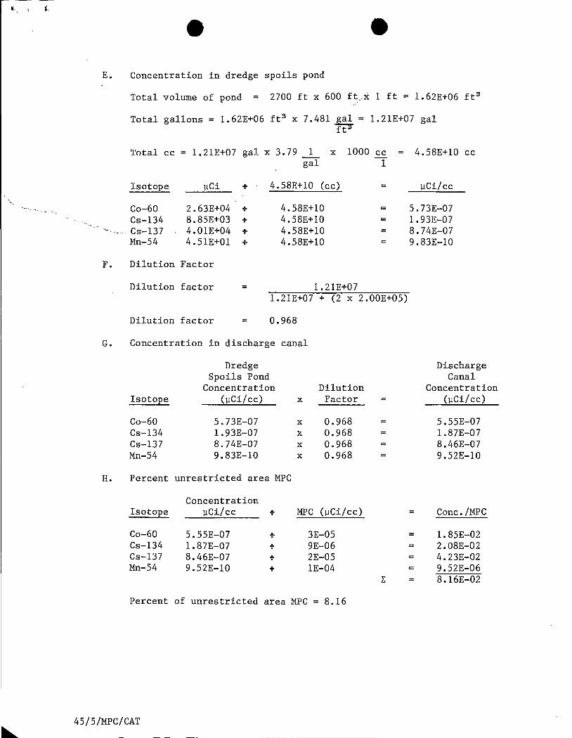
e E. Concentration in dredge spoils pond

Total volume of pond = 2700 ft x 600 ft.x 1 ft= 1.62E+06 ft 3

Total gallons= 1.62E+06 ft 3 x 7.481 gal= 1.21E+07 gal ~

Total cc= 1.21E+07 gal x 3.79 1 x gal

Isotope µCi + 4.58E+l0 (cc)

Co-60 2.63E+04 + 4.58E+l0 Cs-134 8.85E+03 + 4.58E+10

1000 cc = 1

=

= =

·-. ----· Cs-137 4.01E+04 + 4.58E+l0 = Mn-54 4.51E+Ol + 4.58E+l0

F. Dilution Factor

Dilution factor 1.21E+07

Dilution factor

l.21E+07 + (2 x 2.00E+05)

0.968

G. Concentration in discharge canal

Dredge Spoils Pond

Concentration Dilution Isotope (µCi/cc) X Factor =

Co-60 5.73E-07 X 0.968 = Cs-134 1.93E-07 X 0.968 = Cs-137 8.74E-07 X 0.968 = Mn-54 9.83E-10 X 0.968 =

H. Percent unrestricted area MPC

Concentration Isotope µCi/cc + MPG (µCi/cc)

Co-60 5.55E-07 + 3E-05 Cs-134 1. 87E-07 + 9E-06 Cs-137 8.46E-07 + 2E-05 Mn-54 9. 52E-10 + lE-04

Percent of unrestricted area MPC = 8.16

45/5/MPC/CAT

4.58E+10 cc

µCi/cc

5.73E-07 1.93E-07 8.74E-07 9.83E-10

=

= = =

=

Discharge Canal

Concentration (µCi/ cc)

5.55E-07 1.87E-07 8.46E-07 9.52E-10

Cone. /MPC

1.85E-02 2.08E-02 4.23E-02 9.52E-06 8.16E-02

'-- I •

e B. PERCENT UNRESTRICTED AREA MPC CALCULATION -

DREDGING OPERATION

I. Problem

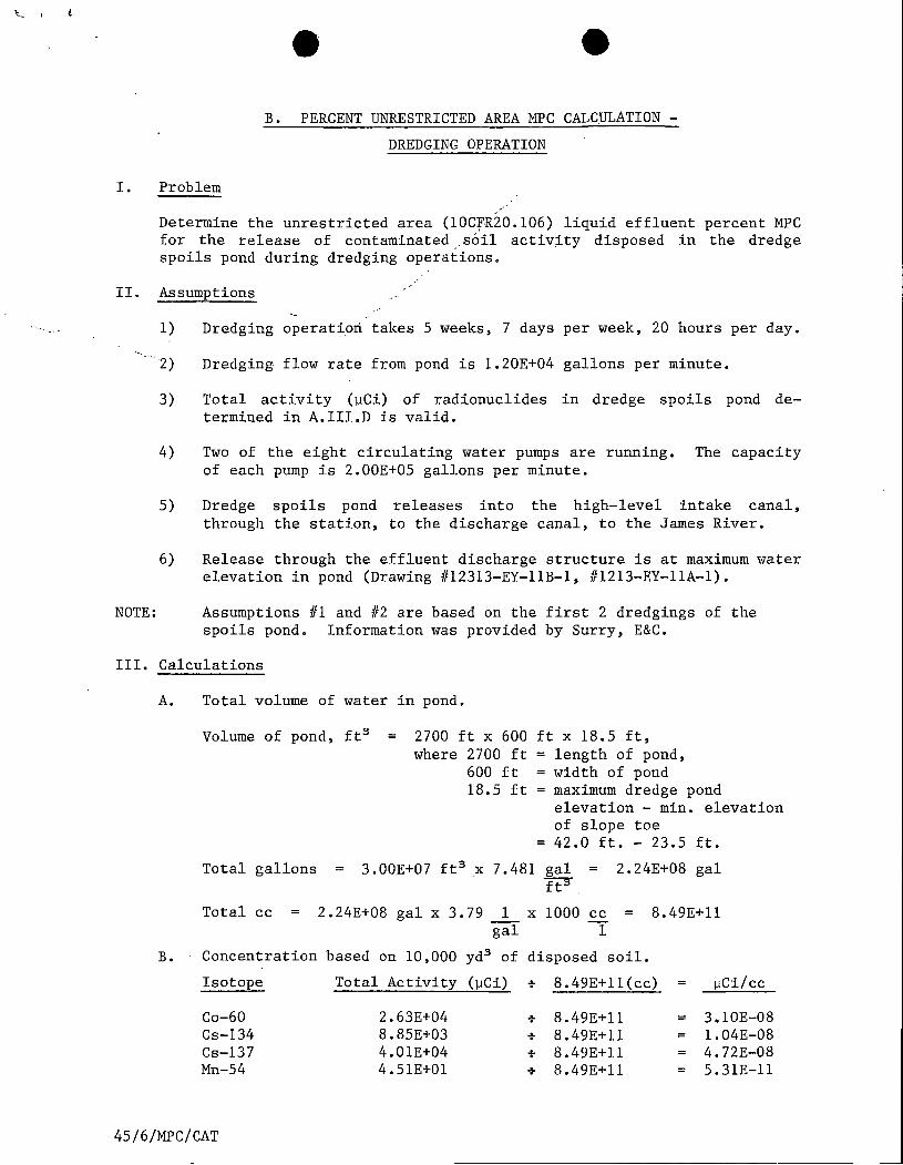
Determine the unrestricted area (10CfR20.106) liquid effluent percent MPC for the release of contaminated .,soil activity disposed in the dredge spoils pond during dredging operations.

II. Assumptions

,,

NOTE:

1) Dredging operat~ori. takes 5 weeks, 7 days per week, 20 hours per day.

2) Dredging flow rate from pond is l.20E+04 gallons per minute.

3) Total activity (µCi) of radionuclides in dredge spoils pond de-termined in A.III.Dis valid.

4) Two of the eight circulating water pumps are running. The capacity of each pump is 2.00E+05 gallons per minute.

5)

6)

Dredge spoils pond releases into the high-level intake canal, through the station, to the discharge canal, to the James River.

Release through the effluent discharge structure is at maximum water elevation in pond (Drawing #12313-EY-llB-l, #1213-EY-llA-l).

Assumptions #1 and #2 are based on the first 2 dredgings of the spoils pond. Information was provided by Surry, E&C.

III. Calculations

A. Total volume of water in pond.

Volume of pond, ft 3 2700 ft X 600 where 2700 ft

600 ft 18.5 ft

ft X 18.5 ft, = length of pond, = width of pond = maximum dredge pond

elevation - min. elevation of slope toe

= 42.0 ft. - 23.5 ft.

Total gallons 3.00E+07 ft 3 X 7.481 gal = 2.24E+08 gal t?"

Total cc = 2.24E+08 gal X 3.79 1 X 1000 cc = 8.49E+ll gal 1

B. Concentration based on 10,000 yd 3 of disposed soil.

Isotope Total Activity (µCi) + 8.49E+ll(cc) µCi/cc

Co-60 2.63E+04 + 8.49E+ll = 3. lOE-08 Cs-134 8.85E+03 + 8.49E+ll = l.04E-08 Cs-137 4.01E+04 + 8.49E+ll 4. 72E-08 Mn-54 4.51E+Ol + 8. 49E+ll 5.31E-ll

45/6/MPC/CAT

~ . . .

C. Dilution factor

Dilution factor = l.20E+04 1.20E+04 + (2 x 2.00E+05)

Dilution factor = 2.91E-02 ,

,/

D. Percent unrestricted area MPC-'

Concentration Dilution Isotope µCi/cc X Factor

Co-60 3.lOE-08 X 2.91E-02 Cs-134 1.04E-08 X 2.91E-02 Cs-137 4.73E-08 X 2. 91E-02 Mn-54 5. 32E-ll X 2. 91E-02

+

+ + + +

Percent of unrestricted area MPC 1.33E-02

45/6/MPC/CAT

MPC

3.0E-05 9.0E-06 2.0E-05 1.0E-04

Concentration = MPC

= 3. OlE-05 = 3.36E-05 = 6.88E-05 = 1.55E-08

z: = 1. 33E-04

.... ' . ..

I. Problem

e C. LIQUID EFFLUENT DOSE CALCULATIONS -

DREDGING OPERATION

Determine the dose commitment to the m~mber(s) of the general public from radioactive material in liquid effluents released from the dredge spoils pond during dredging operation.

II. Assumptions

1) Radioactive mater~~l is only released during dredging operations. /

2) Dredging operation takes 5 weeks, 7 days per week, 20 hours per day. -The pond is designed to contain material for one future dredging.

3) Dredging flow rate from pond is l.20E+04 gallons per minute (4.54E+07 cc/min).

4) Total activity (µCi) of radionuclides in dredge spoils pond de­termined in A.III.Dis valid.

5) Two of the eight circulating water pumps are running. The capacity of each pump is 2.00E+OS gallons per minute.

6) Dredge spoils pond releases into the high-level intake canal, through the station, to the discharge canal, to the James River.

7) Release through effluent discharge structure is at maximum water elevation in pond (Drawing #12313-EY-llB-l, #1213-EY-llA-l).

III. Calculations

A. Total volume of water in pond.

Volume cc = 8.49E+ll cc from B.III.A.

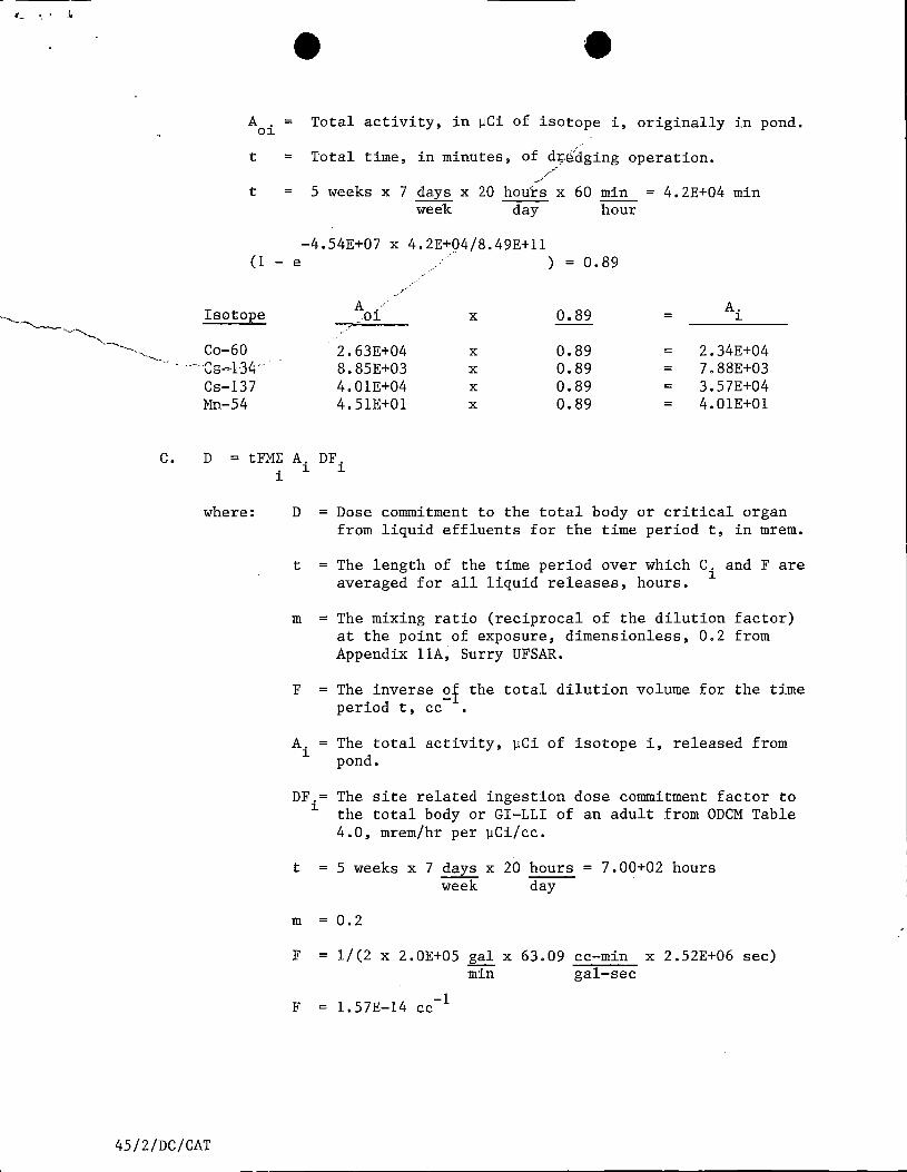
B. Total activity released from pond during dredging operation.

-4.54E+07t/8.49E+ll A. = A . (1 - e )

1 01

where

45/2/DC/CAT

A. = 1

Total activity, in µCi of isotope i, released from pond at time t.

'',----.....___, __ ~

e A = Total activity, in µCi of isotope i, originally in pond. oi

t = Total time, in minutes, of dr.(idging operation. --/

/

t = 5 weeks X 7 days X 20 hours X 60 min 4.2E+04 min week day hour

-4.54E+07 x 4.2E+Q4/8.49E+ll (1 - e ) = 0.89

~/-· -

Isotope A A . . oi X 0.89 = l ,

-'-------...

Co-60 2.63E+04 X 0.89 = 2.34E+04 --·cg-~134-- 8.85E+03 X 0.89 = 7.88E+03

Cs-137 4.01E+04 X 0.89 3.57E+04 Mn-54 4.51E+Ol X 0.89 = 4.0lE+Ol

C. D = tFM~ A. DF. i l l

where: D = Dose commitment to the total body or critical organ from liquid effluents for the time period t, in mrem.

t = The length of the time period over which C. and Fare l averaged for all liquid releases, hours.

m = The mixing ratio (reciprocal of the dilution factor) at the point of exposure, dimensionless, 0.2 from Appendix llA~ Surry UFSAR.

F = The inverse ~f the total dilution volume for the time period t, cc .

A. = The total activity, µCi of isotope l

i, released from pond.

DF.= The site related ingestion dose commitment factor to l the total body or GI-LLI of an adult from ODCM Table

4.0, mrem/hr per µCi/cc.

t 5 weeks x 7 days x 20 hours= 7.00+02 hours week day

m 0.2

F = 1/(2 x 2.0E+OS gal x 63.09 cc-min x 2.52E+06 sec)

F l.57E-14 -1 cc

min gal-sec

45/2/DC/CAT

, ... I• l

D. Total Body Dose .

Isotope A,(µCi) X DF. (mrem/hr) = mrem-cc l. l. µCi/cc hr

Co-60 2.34E+04 X 3.82E+03 8.94E+07 Cs-134 7.88E+03 X l.33E+04 = l.05E+08 Cs-137 3.57E+04 -·X 7.85E+03 = 2.80E+08 Mn-54 4. OlE+Ol .-·' l.35E+03 5.41E+04 X = .,-"''

I: = 4.75E+08

·-'-. = 7.00E+02 (hr) x l.57E-14(cc-1) x 4.75E+08(mr~;-cc) ....__,_~- D(Total Body) --~

............... h ••

D(Total Body)= 5.22E-03 mrem

E. GI-LLI Dose

Isotope A.(µCi) X DF. (mrem/hr) = mrem-cc l. l. µCi/cc hr

Co-60 2.34E+04 X 3.25E+04 = 7. 61E+08 Cs-134 7.88E+03 X 2.85E+02 = 2.25E+06 Cs-137 3.57E+04 X 2.32E+02 = 8.28E+06 Mn-54 4. OlE+Ol X 2.16E+04 = 8.66E+05

I: = 7.72E+08

D(GI-LLI) = 7.00E+02 (hr) X -1 7. 72E+08 (mrem-cc) l.57E-14(cc ) X hr

D(GI-LLI) 8.48E-03 mrem

45/2/DC/CAT

Nuclide

Co-60 Cs-134 Cs-137 Mn-54

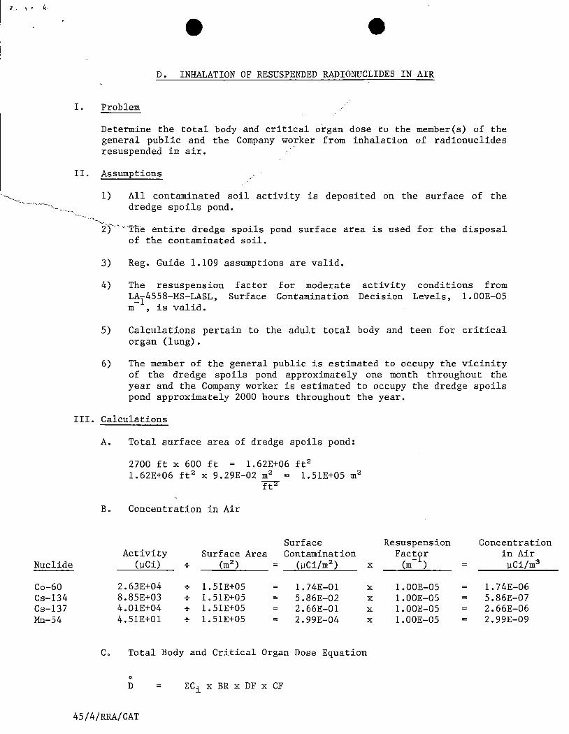
e D. INHALATION OF RESUSPENDED RADIONUCLIDES IN AIR

I. Problem

Determine the total body and critical organ dose to the member(s) of the general public and the Company worker from inhalation of radionuclides resuspended in air.

II. Assumptions

1) All contaminated soil activity is deposited on the surface of the dredge spoils pond.

_..,_

------iy' ---Tlie entire dredge spoils pond surface area is used for the disposal of the contaminated soil.

3) Reg. Guide 1.109 assumptions are valid.

4) The resuspension factor L~y4558-MS-LASL, Surface m , is valid.

for moderate Contamination

activity Decision

conditions from Levels, l.OOE-05

5) Calculations pertain to the adult total body and teen for critical organ (lung).

6) The member of the general public is estimated to occupy the vicinity of the dredge spoils pond approximately one month throughout the year and the Company worker is estimated to occupy the dredge spoils pond approximately 2000 hours throughout the year.

III. Calculations

A. Total surface area of dredge spoils pond:

2700 ft x 600 ft = l.62E+06 ft 2

l.62E+06 ft 2 X 9.29E-02 m2 = l.51E+05 m2

12"

B. Concentration in Air

Surface Activity Surface Area Contamination

(µCi) + (m2) = (µCi/m 2)

2.63E+04 + 1. 51E+05 = 1. 74E-01 8.85E+03 + l.51E+05 = 5.86E-02 4. 01E+04 + l.51E+05 2.66E-01 4.51E+Ol + l.51E+05 = 2.99E-04

C. Total Body and Critical Organ Dose Equation

0

D ECi x BR x DF x CF

45/4/RRA/CAT

Resuspension Concentration Fac!~r in Air

X (m ) = µCi/m3

X l.OOE-05 = l.74E-06 X l.OOE-05 = 5.86E-07 X l.OOE-05 2.66E-06 X l.OOE-05 2.99E-09

It/., 'i \) JI.

where: 0

D = The total body or critical organ (lung) annual dose, mrem.

C. = Concentration of radionuclide~ µCi/m 3

1

BR = Breathing rate of a teen or adult, 8.00E+03m3 /yr,R.G.1.109.

DF = Inhalation total body dose factor for an adult or inhalation lung dose factor for a teen, mrem/pCi,R.G.1.109.

CF. ConversiorC factor, 1. OOE+06 pCi/µCi.

·,·,J),. ______ Total Body Annual Dose to an Adult. 0

Ci BR DF CF D Nuclide (µCi/m3

) X (m3 /yr) X (mrem/pCi) X (pCi/µCi) = (mrem/yr)

Co-60 1. 74E-06 X 8.00E+03 X 1. 85E-06 X 1.00E+06 2.58E-02 Cs-134 5.86E-07 X 8.00E+03 X 9. lOE-05 X 1.00E+06 = 4.27E-01 Cs-137 2.66E-06 X 8.00E+03 X 5.35E-05 X 1.00E+06 = 1.14E+OO Mn-54 2.99E-09 X 8.00E+03 X 7.87E-07 X 1.00E+06 = 1.88E-05

E 1.59

Member of general public: Annual dose for 744 hours occupancy = 1.35E-01 mrem.

Company worker: Annual dose for 2000 hours occupancy = 3.63E-01 mrem.

E. Critical Organ (Lung) Annual Dose to a Teen 0

Ci BR DF CF D Nuclide (µCi/m 3

) X (m3 /yr) X (mrem/pCi) X (mrem/µCi) = (mrem/yr)

Co-60 1.74E-06 X 8.00E+03 X 1.09E-03 X 1.00E+06 = L 52E+Ol Cs-134 5.86E-07 X 8.00E+03 X 1.83E-05 X 1.00E+06 = 8.58E-02 Cs-137 2.66E-06 X 8.00E+03 X 1. 5 lE-05 X l.OOE+06 = 3.21E-01 Mn-54 2.99E-09 X 8.00E+03 X 2.48E-04 X 1.00E+06 = 5.93E-03

E = 1.56E+Ol

Member of general public: Annual dose for 744 hours occupancy = 1.33E+OO mrem.

Company worker: Annual dose for 2000 hours occupancy= 3.56E+OO mrem.

45/4/RRA/CAT

E. DOSE FROM EXTERNAL.IRRADIATION FROM

RADIONUCLIDES DEPOSITED ON GROUND SURFACE

I. Problem

Determine the annual dose to the member(s) of the general public and the Company worker from external radiation due to radionuclides deposited onto the ground surface.

II. Assumptions

-1.) All contaminated soil activity is deposited onto the surface of the dredge spoils pond.

2) The dredge spoils pond is a volume slab source of infinite extent having a finite thickness with self-absorption (61 cm).

3) The gamma flux is uniform throughout the volume source.

4) The equation for calculating the gamma flux for a thick slab of infinite extent with self-absorption contained in Reactor Shielding Design Manual, T. Rockwell III, is valid.

5) The density of soil is 2.2 g/cc.

6) The member (s) of the general public is estimated to occupy the vicinity of the dredge spoils pond approximately one month throughout the year and the Company worker is estimated to occupy the dredge spoils pond approximately 2000 hours throughout the year.

III. Calculations

A. From sample results, the following average isotopic concentrations were determined:

B.

45/7 /EI/CAT

Isotope

Co-60 Cs-134 Cs-137 Mn-54

0

0 =

Sv =

Jls

E2(b3)

Concentration (µCi/cc)

Sv 2µ

s , where

gamma flux, photons/cc-sec.

-1 -1 source strength, cc sec

l.56E-06 5.26E-07 2.38E-06 2.68E-09 4.47E-06

-1 linear absorption coefficient, cm

integral exponential function equal to 5.0E-04 for b = 3 to 10, Rockwell graph, p. 374 Rockwell Manual.

e = µ x h, where his the amount of soil providing

s~lf-absorption, equal to 61 cm.

1. From NBS Handbook No. 29, the i~ferpolated value ofµ for 1.33 MeV gamma photons is 9.2E-02 cm s

2. b3 =

b3 =

b3 =

3. Sv =

Sv =

4.

µs X h -1 9.2E-02 cm X 61 cm

5.61

4.47E-06µCi/cc x 3.7E+04 l.65E-01 photons/cc-sec

Sv

2µ s

dps/µCi

1.65 E-01 photons/cc-sec (5 .0E-04) 2 x 9.2E-02cm- 1

4.48E-04 photons/cm2 -sec

5. From ANSI 6 .1.1., the gamma ray flux to dose rate conversion factor for 1.4 MeV gamma photons is 2.51E-06 rem/hr per photon/cm2 -sec. The 1.4 MeV energy is more conservative than the actual isotopic energies.

6. Dose Rate (mrem/hr) = 2.51E-06 x 4.48E-04 = l.12E-09 rem/hr

l.12E-06 mrem/hr

Member(s) of the general public: Annual dose for 744 hours (one month) occupancy = 8.33E-04 mrem

Company worker: Annual dose for 2000 hours occupancy = 2.24E-03 mrem.

45/7 /EI/CAT


Recommended