31
Survey of Experience with Integrated Metocean and Structural Integrity Monitoring on 36 Deepwater ProductionSystems Presenter: Thomas L. Johnson

Survey of Experience with
Integrated Metocean and Structural
Integrity Monitoring
on 36 Deepwater ProductionSystems
Presenter: Thomas L. Johnson

Presentation Objectives
• Describe Integrated Metocean and Structural Integrity
for Deepwater Floating Production Systems
• Present the rationale for monitoring
• Give some examples of what is measured and how
the information is used

Typical Deepwater Floating Production Systems

Goals of Integrated Marine Monitoring
Systems (IMMS)
• Monitor “marine” parameters (as distinct from drilling
system parameters or process control parameters)
• To provide:
Real–time operational decision support
Archived data on a common time base for:
integrity management,
forensic analysis,
verification of engineering design tools.
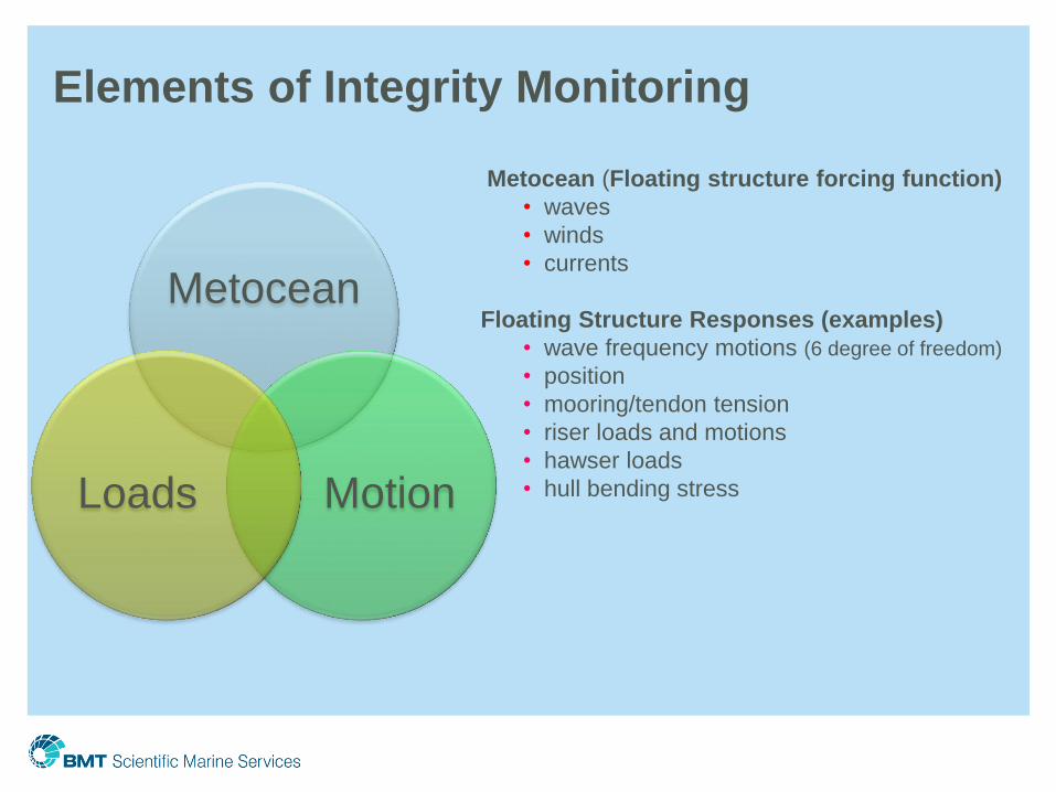
Elements of Integrity Monitoring
Metocean
Motion Loads
Metocean (Floating structure forcing function)
• waves
• winds
• currents
Floating Structure Responses (examples)
• wave frequency motions (6 degree of freedom)
• position
• mooring/tendon tension
• riser loads and motions
• hawser loads
• hull bending stress

Rationale for Monitoring (following 4 slides in extended abstract)
Operational Decision SupportForensic
Engineering
Verification of Design
Tools
Integrity
Monitoring
Measurement Subsystem Installation Running Riser Drilling Production
Air Gap/Waves Not Functional Guidance on managing service vessel, crane and heavy lift operations
Estimate Run-Up; Assess
wave damages;
Characterize environment
Characterize Environmental forcing
functions
Input to Damage
Prediction Models
Wave Direction Not Functional Guidance on managing service vessel, crane and heavy lift operations
Estimate Run-Up; Assess
wave damages;
Characterize environment
Characterize Environmental forcing
functions
Input to Damage
Prediction Models
Wind Speed and Direction Not FunctionalGuidance on managing Helicopter,service vessel, crane and heavy lift
operations
Assess Topsides
damage;Characterize
environment
Characterize Environmental forcing
functions
Input to Damage
Prediction Models
"Surface Current"Guidance on managing
service vessel operationsGuidance on managing service vessel operations
evaluate cause of mooring
failures or observed platform
Vortex Induced Motion
Characterize Environmental forcing
functions-Validate Hull VIM Models
Input to Damage
Prediction Models
Current ProfileGuidance on managing
subsea operations
Identify excessive
currents
Identify excessive
currentsN/A
Determine cause of riser
loads
Characterize Environmental forcing
of risers
Input to Fatigue
Damage Prediction
Models
Bottom Current (Profile)Guidance on managing
subsea operations
Identify excessive
currents
Identify excessive
currentsN/A
Determine cause of riser
loads
Characterize Environmental forcing
of risers
Input to Fatigue
Damage Prediction
Models
Pressure/Temperature/Humidity Not FunctionalAdvance storm forecasting for Helicopter,service vessel, crane and
heavy lift operations
Verify hurricane/storm
intensityN/A N/A
Platform Attitude and Motions (0.0
and 0.01 Hz -1Hz)
TLP- check trim and list
prior to tendon lock-off to
ensure platform installed
level
Guidance on managing heavy lift operationsEstimate excitation of
SCR's and production risers Verify Global Motion Models
Estimate Fatigue
damage in SCR's;
Foundations of Large
tanks/Derrick
Platform Position and Motions (0.00
Hz -0.01Hz)-within 150 Nautical Miles
of USCG Stations
Check Mooring Set Up
and on SCR's to verify
installed angle
Positioning Platform over subsea well heads
Mooring System
Adjustment in
Anticipation of weather
or high curents
Estimate excitation of
SCR's and Production
Risers, Mooring loads
Verify Global Motion Models; VIM
Models
Quasi static loads
on Mooring
Equipment
Platform True Heading (Low
frequency yaw)
Check As Installed
Heading and on SCR's to
verify installed angle
Positioning Platform over subsea well heads Mooring System
Adjustment
Estimate excitation of
SCR's Verify Global Motion Models
Estimate excitation
of SCR's
Production Riser Tensions and
Bending Moments Not Functional Set Riser Tension
Manage riser tension
factor
Manage riser tension
factor
identfy performance
problems
Verify Riser Responses and fatigue
models
Riser Fatigue
Damage
Production Riser Stroke Not Functional Not Functional N/AWarn of Approach to
Stops
identify excessive riser
excursions; identify failure of
B Cans to slip in guides
Verify Riser Quasi Static
Responses N/A
Air Can pressures Not Functional Set TensionMaintain Tension and
Identify sources of leaksExplain Tension Loss N/A
Track integrity of
chambers
Air Can Riser Guide Compression Not Functional N/A N/A N/AAssess loads on Buoyancy
CansAssess Load Estimation Models N/A
Tendon Tensions Set Tensions N/A N/AMaintain Tension and
Weight Distributioninvestigate tendon failures
Validate Tendon Tension Estimating
Models
insure that CG is
within proper limits;
identify degradation
in tendon anchors
Mooring Line Tensions and Payout Set TensionsPositioning over
subsea wellheads
Positioning over
subsea wellheads
Tension Adjustment for
high currents and
Hurricanes
Identify causes of Mooring
Failures and quantify time-
on-link for fatigue estimation
Verify Global Motion Models
Track mooring line
fatigue damage;
anchor failures
DraftTLP- use to verify
installed tendon tensionsN/A N/A Ballast/Trim/Heel Control
establish causes of errors in
ballast controlRequired for chracterization of hull
Identify sinkage due
to leaks/collision
damage
Ballast Tank LevelsTLP- use to verify
installed tendon tensionsN/A N/A Ballast Trim Heel Control
establish causes of errors in
ballast controlRequired for chracterization of hull
Track Intact and
Damaged Stability
Steel Catenary Riser
Inclination/Vibration
Verify SCR Installed
inclinationN/A N/A N/A
help to identify reasons for
component filure or
degradation
verify Floater Motion induced
response in SCR
Estimate and Track
SCR Fatigue

Rationale Matrix • Operational Decision Support (installation, riser running, drilling, production)
• Forensic Engineering
• Verification of Design Tools
• Integrity Management
• Air Gap measurements
• Wind speed and direction measurements
• Current measurements
• Platform 6 degree of freedom motions / position measurements
• Mooring load measurements
• Riser strain, tension, bending and motion measurements
• Ballast level measurements
• etc.
mapped onto

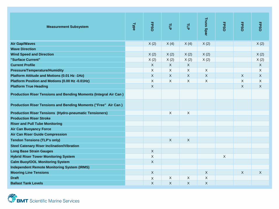
Measurement Subsystem
Typ
e
Sem
i-su
bm
ers
ible
TL
P
Cla
ssic
Sp
ar
Tru
ss S
pa
r
Tru
ss S
pa
r
Tru
ss S
pa
r
Cell S
pa
r
TL
P
TL
P
Sem
i-su
bm
ers
ible
Tru
ss S
pa
r
Tru
ss S
pa
r
Tru
ss S
pa
r
TL
P
Sem
i-su
bm
ers
ible
Sem
i-su
bm
ers
ible
Air Gap/Waves
X (4) X (3) X (2) X (4) X (2) X (2) X (2) X (4) X (4) X (2) X (4) X (4) X (4) X (4)
Wave Direction X
Wind Speed and Direction
X (2) X (2) X (2) X (2) X (2) X (2) X (2) X (2) X (2) X (2) X (2) X (2) X (3) X (2)
"Surface Current"
X (2) X X X (2) X X X X X X
Current Profile X X X X X X X X X X X X
Pressure/Temperature/Humidity X X X X X X X X X X X
Platform Attitude and Motions (0.01 Hz -
1Hz) X X X X* X X X X X X X X X
X (2
DOF) X X
Platform Position and Motions (0.00 Hz -
0.01Hz) X (2) X X X (2) X X X X (2) X (2) X (2) X (2) X (2) X (2) X X
Platform True Heading X X X X X X Production Riser Tensions and Bending
Moments (Integral Air Can )
Production Riser Tensions and Bending
Moments ("Free" Air Can ) X X X X
Production Riser Tensions (Hydro-
pneumatic Tensioners) X X
Production Riser Stroke
X (15) X (4) X (4)
Riser and Pull Tube Monitoring Air Can Buoyancy Force X Air Can Riser Guide Compression X Tendon Tensions (TLP's only) X X X X Steel Catenary Riser
Inclination/Vibration X X X
Long Base Strain Gauges Hybrid Riser Tower Monitoring System Calm Buoy/OOL Monitoring System Independent Remote Monitoring System
(IRMS) X X X X X X X X X X X X X
Mooring Line Tensions X X X X X X X X X X
Draft X X X X X X X X X X X X X X
Ballast Tank Levels X X X X X X X X X X X X X

Measurement Subsystem
Typ
e
Se
mi-s
ub
me
rsib
le
Cla
ss
ic S
pa
r
Tru
ss
Sp
ar
TL
WP
TL
P
TL
P
Tru
ss
Sp
ar
Se
mi-s
ub
me
rsib
le
Tru
ss
Sp
ar
Se
mi-s
ub
me
rsib
le
Tru
ss
Sp
ar
Sp
ar
TL
P
Air Gap/Waves
X (4) X-laser
(1) X (4) X (2) X (2) X (2) X(2) X (2) X (2) X (4) X (2)
Wave Direction X X X
Wind Speed and Direction X (2) X (2) X (2) X X X X X (2) X X (2) X (2) X (2) X (2)
"Surface Current" X X X X (2) X X
Current Profile X X X X X X X X X X X
Pressure/Temperature/Humidity X X X X X X X X X X X X X
Platform Attitude and Motions (0.01 Hz -1Hz)
X X X X X (5
DOF)
X (5
DOF) X X X X X
X (3
DOF)
Platform Position and Motions (0.00 Hz -0.01Hz)
X X X X (2) X (2) X X X X X X X
Platform True Heading X X X X X X
Production Riser Tensions and Bending
Moments (Integral Air Can ) X
Production Riser Tensions and Bending
Moments ("Free" Air Can ) X X X
Production Riser Tensions (Hydro-pneumatic
Tensioners) X X
Production Riser Stroke X
Riser and Pull Tube Monitoring X
Air Can Buoyancy Force
Air Can Riser Guide Compression
Tendon Tensions (TLP's only) X X X X
Steel Catenary Riser Inclination/Vibration
Long Base Strain Gauges
Hybrid Riser Tower Monitoring System
Calm Buoy/OOL Monitoring System
Independent Remote Monitoring System (IRMS)
Mooring Line Tensions X X X X X X X X
Draft X X X X X X X X X X
Ballast Tank Levels X X X X X X X X X
Measurement Subsystem
Typ
e
FP
SO
TL
P
TL
P
Tru
ss
Sp
ar
FP
SO
FP
SO
FP
SO
Air Gap/Waves X (2) X (4) X (4) X (2) X (2)
Wave Direction
Wind Speed and Direction X (2) X (2) X (2) X (2) X (2)
"Surface Current" X (2) X (2) X (2) X (2) X (2)
Current Profile X X X X
Pressure/Temperature/Humidity X X X X X
Platform Attitude and Motions (0.01 Hz -1Hz) X X X X X X
Platform Position and Motions (0.00 Hz -0.01Hz) X X X X X X
Platform True Heading X X X
Production Riser Tensions and Bending Moments (Integral Air Can )
Production Riser Tensions and Bending Moments ("Free" Air Can )
Production Riser Tensions (Hydro-pneumatic Tensioners) X X
Production Riser Stroke
Riser and Pull Tube Monitoring
Air Can Buoyancy Force
Air Can Riser Guide Compression
Tendon Tensions (TLP's only) X X
Steel Catenary Riser Inclination/Vibration
Long Base Strain Gauges X
Hybrid Riser Tower Monitoring System X X
Calm Buoy/OOL Monitoring System X
Independent Remote Monitoring System (IRMS)
Mooring Line Tensions X X X X
Draft X X X X
Ballast Tank Levels X X X X

Microwave Radar Air Gap Sensor

Operational Decision Support & Design Verification
Airgap Sensor derived Hs vs. NDBC wave buoy nearby
0
2
4
6
8
10
12
14
16
1-O
ct
7-O
ct
13-O
ct
19-O
ct
25-O
ct
31-O
ct
Sig
nif
ican
t W
ave H
eig
ht
Hs (
ft)
Hs (AirGap Sensor)
Hs (NDBC 42041)

Anemometer Installed on Crane Top

Operational Decision Support
Helideck Display (CAP 437 Compliant)

38 kHz ADCP Deep Current Profiler

ROV Deployable HADCP on Greater Plutonio FPSO
Outward Looking (Hybrid Riser Tower Acoustic
Positioning System shared the Fixture with the HADCP)

Bottom Mounted 75 kHz ADCP with acoustic modem in
approximately 4,500 ft of water near BP’s Mad Dog spar

Operational Decision Support (riser running, ROV Ops)
Typical screen plot of Combined Current Profile

Forensics, Design Verification & Integrity Management
Client Data Center (CDC)

Vortex Induced Motions (VIM) • Vortex-Induced Motions
(VIM) are motions induced
on large floating bodies
interacting with an external
fluid flow, produced by – or
the motion producing –
periodical irregularities of
this flow.
• VIM, if prolonged, could
cause riser and mooring
fatigue.
• VIM, when fully locked in,
could dramatically escalate
the drag loads on the
structure causing mooring
damage.
• Increased loading would
also cause increased
platform offset.
-0.1
0.0
0.1
0.2
0.3
0.4
0.5
-0.2-0.10.00.10.20.30.4
Sway/D
Su
rg
e/D
D
A/D
Ur=UT/D
Figure 1: : A/D vs. Ur
Vortex shedding
Lock-in
Vessel Excursion
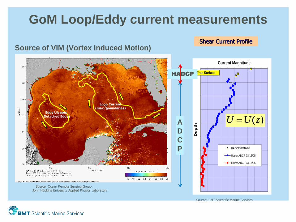
Source of VIM (Vortex Induced Motion)
Source: Ocean Remote Sensing Group, John Hopkins University Applied Physics Laboratory
Loop Current (max. boundaries)
Eddy Ulysses (Detached Eddy)
GoM Loop/Eddy current measurements
0
500
1000
1500
2000
2500
3000
3500
4000
4500
0 100 200 300 400 500 600 700 800 900 1000
Current Magnitude
De
pth
HADCP 03/16/05
Upper ADCP 03/16/05
Lower ADCP 03/16/05
Free Surface
Shear Current Profile
( )U U z
Source: BMT Scientific Marine Services
HADCP
A
D
C
P

Power spectral density plots (by day)
• Color indicates
higher/lower energy
• 100 to 300 seconds
typical mooring
horizontal natural
frequency
• Plots can be used to
quickly evaluate
whether VIM was likely
occurring
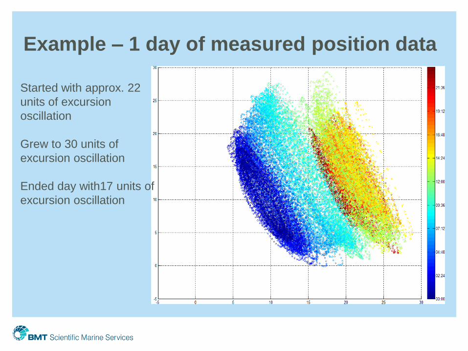
Example – 1 day of measured position data
Started with approx. 22
units of excursion
oscillation
Grew to 30 units of
excursion oscillation
Ended day with17 units of
excursion oscillation

Why is it important to investigate full scale VIM
responses?
Contrary to MMS workshop (held 22-24 October 2003) entitled “Spar
Vortex-Induced Motions” not only spars experience VIM.
However
• If VIM does not occur as frequently or
• VIM does not have the expected magnitude
Then
• May be over-designing moorings and risers substantially
Next question
• Why is it not as big or frequent?
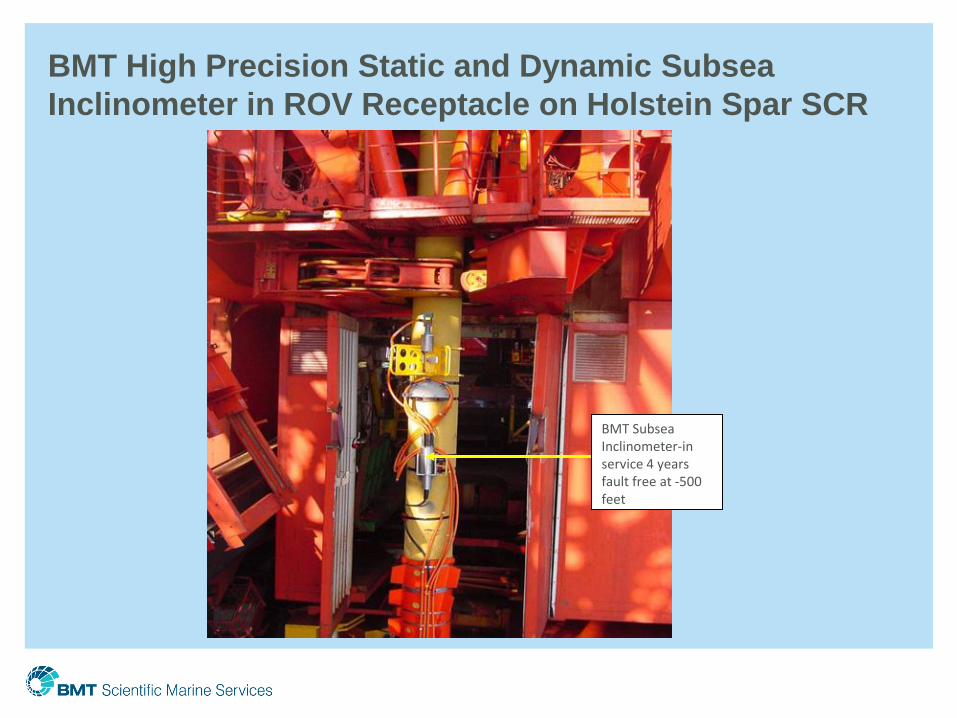
BMT High Precision Static and Dynamic Subsea
Inclinometer in ROV Receptacle on Holstein Spar SCR
BMT Subsea Inclinometer-in service 4 years fault free at -500 feet

BMT High Precision Static and Dynamic Subsea
Inclinometer (4 Degree of Freedom Inertial Package)

Comparison of Imposed and Measured Inclination
(actual spar inclination record used for test)

Impact of Tropical Storm on Mooring Tension

Semi-log TS Plot of Mooring Fatigue Damage

Detail – Why Accumulated Fatigue Jumped
60
55
50
45
40
35
30
25
20

Thank you


