15 th International Brick and Block Masonry Conference Florianópolis – Brazil – 2012 Sustainable Dry Interlocking Block Masonry Construction BANSAL DEEPAK 1 1 Dy General Manager (Projects), HUDCO, Hudco Bhawan, Delhi 110003, INDIA, & Research Scholar with TERI University, New Delhi, India.Email: [email protected]ABSTRACT There is a need to identify innovative technologies to supplement age-old concrete and burnt clay brick mortar based construction for masonry work. Today we need technologies which are sustainable in terms of one or more of the following parameters i.e. use of locally available resources – material & manpower, cost effectiveness, eco-friendly, easy to adopt in construction practice, can be cast – in situ to reduce transportation, faster to build and energy efficient. The Indian masonry design standard (IS 1905-1987) does not deal with dry interlocking block masonry, hence does not prescribe the design values for this masonry like basic compressive strength, tensile strength & shear strength. However the same code recognizes other types of masonry and recommends that a prism test of different masonry may be done and these values may be accepted for designing the masonry. This block masonry by Hydraform interlocking (this is a typical case in this study, but can be generic) has been tested in the field as well as by experiments and has been found to have better strength than the conventional brick masonry (burnt clay bricks in English bond) using cement sand mortar (1:6). The basic compressive strength is much more than the minimum values given in the Indian masonry design standard (IS 1905-1987). These blocks have low embodied energy compared to burnt clay brick, and can be specifically designed as per requirements, resulting in promotion of green construction technology. The paper addresses the technical specifications, raw material options, construction procedure, structural performance, embodied energy and conformity with the building standards. Key Words: Interlocking Block Masonry, Embodied Energy, Crushing Strength, Flyash, 1 INTRODUCTION The dry stacked interlocking block masonry replaces the conventional brick and mortar construction masonry by interlocking blocks masonry construction. The other components of the conventional building system remain largely unchanged. The system is a dry stacked Interlocking masonry but can be done with mortar/slurry/grout also that enables aesthetic and affordable building, speedier construction of high quality in stretcher bond, and as well as in the normal English/Flemish bond with mortar. The blocks have an extremely appealing face- brick/wash finish and provide a pre-pointed straight masonry. The walls may be left exposed, plastered/rendered or finished with cement wash. The system has originated during the time of Egyptian pyramids construction and may be even before that period, and has extensively been in use over different continents. A number of constructions have been made using interlocking building system in India over last decades. The interlocking block masonry system is not uniform in India, and as per information available with the author, there are three types of interlocking blocks available (as per information available with author) in India: 1. Hydraform Interlocking Blocks ( stabilized earth blocks(SEB) and fly ash blocks)
Transcript
15th International Brick and Block Masonry Conference
Florianópolis – Brazil – 2012
Sustainable Dry Interlocking Block Masonry Construction
BANSAL DEEPAK1
1 Dy General Manager (Projects), HUDCO, Hudco Bhawan, Delhi 110003, INDIA, & Research Scholar with TERI University, New Delhi, India.Email: [email protected]
ABSTRACT There is a need to identify innovative technologies to supplement age-old concrete and burnt clay brick mortar based construction for masonry work. Today we need technologies which are sustainable in terms of one or more of the following parameters i.e. use of locally available resources – material & manpower, cost effectiveness, eco-friendly, easy to adopt in construction practice, can be cast – in situ to reduce transportation, faster to build and energy efficient. The Indian masonry design standard (IS 1905-1987) does not deal with dry interlocking block masonry, hence does not prescribe the design values for this masonry like basic compressive strength, tensile strength & shear strength. However the same code recognizes other types of masonry and recommends that a prism test of different masonry may be done and these values may be accepted for designing the masonry. This block masonry by Hydraform interlocking (this is a typical case in this study, but can be generic) has been tested in the field as well as by experiments and has been found to have better strength than the conventional brick masonry (burnt clay bricks in English bond) using cement sand mortar (1:6). The basic compressive strength is much more than the minimum values given in the Indian masonry design standard (IS 1905-1987). These blocks have low embodied energy compared to burnt clay brick, and can be specifically designed as per requirements, resulting in promotion of green construction technology. The paper addresses the technical specifications, raw material options, construction procedure, structural performance, embodied energy and conformity with the building standards. Key Words: Interlocking Block Masonry, Embodied Energy, Crushing Strength, Flyash,
1 INTRODUCTION
The dry stacked interlocking block masonry replaces the conventional brick and mortar construction masonry by interlocking blocks masonry construction. The other components of the conventional building system remain largely unchanged. The system is a dry stacked Interlocking masonry but can be done with mortar/slurry/grout also that enables aesthetic and affordable building, speedier construction of high quality in stretcher bond, and as well as in the normal English/Flemish bond with mortar. The blocks have an extremely appealing face-brick/wash finish and provide a pre-pointed straight masonry. The walls may be left exposed, plastered/rendered or finished with cement wash. The system has originated during the time of Egyptian pyramids construction and may be even before that period, and has extensively been in use over different continents. A number of constructions have been made using interlocking building system in India over last decades. The interlocking block masonry system is not uniform in India, and as per information available with the author, there are three types of interlocking blocks available (as per information available with author) in India:
15th International Brick and Block Masonry Conference
Florianópolis – Brazil – 2012
2. IIT Delhi, India, fly ash interlocking blocks 3. IIT Madras, India, cement concrete interlocking blocks
Out of all these interlocking blocks, the author has the practical working experience only with Hydra form interlocking blocks, and the same is explained in this paper. However the same is generic and can be extended with other types of interlocking blocks also. Stabilized earth blocks (SEB) are produced with local sandy loam type of soil with cement or lime or gypsum as stabilizer and are pressed in a hydraulic press in a mould, cured for 7 days and used as masonry blocks. The typical composition of SEB block chosen is given in table no 2 and fly ash block is given in table no 3.The amount of stabilization depends on the soil characteristics and strength desired, but generally varies from 2-10% by weight.
2 INTERLOCKING MASONRY FEATURES
2.1 Interlocking Block
2.2 Interlocking Profile
The locking of a male face of one block with the female face of another or the locking of the bed of one block with the ridge of the one below , is called Interlock.
2.3 Bed and Ridge
The recessed under surface of the block is referred to as the bed. The raised top surface of the block is called the Ridge.
Figure 1. Interlocking Block
Figure 2. Placing of Interlocking Blocks
15th International Brick and Block Masonry Conference
Florianópolis – Brazil – 2012
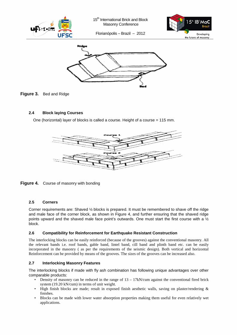
2.4 Block laying Courses
One (horizontal) layer of blocks is called a course. Height of a course = 115 mm.
2.5 Corners
Corner requirements are: Shaved ½ blocks is prepared. It must be remembered to shave off the ridge and male face of the corner block, as shown in Figure 4, and further ensuring that the shaved ridge points upward and the shaved male face point’s outwards. One must start the first course with a ½ block.
2.6 Compatibility for Reinforcement for Earthquake Resistant Construction
The interlocking blocks can be easily reinforced (because of the grooves) against the conventional masonry. All the relevant bands i.e. roof bands, gable band, lintel band, cill band and plinth band etc. can be easily incorporated in the masonry ( as per the requirements of the seismic design). Both vertical and horizontal Reinforcement can be provided by means of the grooves. The sizes of the grooves can be increased also.
2.7 Interlocking Masonry Features
The interlocking blocks if made with fly ash combination has following unique advantages over other comparable products:
• Density of masonry can be reduced in the range of 13 – 17kN/cum against the conventional fired brick system (19.20 kN/cum) in terms of unit weight.
• High finish blocks are made; result in exposed finish aesthetic walls, saving on plaster/rendering & finishes.
• Blocks can be made with lower water absorption properties making them useful for even relatively wet applications.
Figure 3. Bed and Ridge
Figure 4. Course of masonry with bonding
15th International Brick and Block Masonry Conference
Florianópolis – Brazil – 2012
• Dry-stacked masonry results in speedier construction. • Blocks can be made with reinforcement / conduit features facilitating earthquake resistant construction. • Blocks made are eco friendly as no burning is involved
2.8 The Interlocking Building System
It comprises of three primary aspects: (1) Interlocking Block (2) Block making Machine (3) Advantages of interlocked stacking of blocks
2.9 Interlocking Masonry System
The interlocking dry stacked masonry comprises of SEB (stabilized earth blocks) / fly-ash interlocking blocks that can be laid dry - stacked or using minimal mortar slurry/grout in a stretcher bond. Dry stacking is mortar- less method of masonry construction. Except first two block layers/courses above DPC( damp proof course of 40mm thick plain cement concrete of M20 mix at plinth level) and top two courses leading to roof band(if required ), blocks are not laid on mortar but can be laid with cement slurry, they rely on the interlocking mechanism to provide resistance to applied loads. Dry stacking results in reduction of building costs due to saving in construction time, reduced requirement for skilled labour and costly material especially cement and reusability of the blocks. The usage of unskilled labour makes dry stacking particularly attractive when compared with masonry with use of mortar. With an extremely appealing face-brick finish that provides for pre-pointed straight masonry, these blocks gives flexibility of achieving the final finish. The masonry uses minimal or no mortar, construction is fast, blocks are produced on the site saving transportation cost, requirement of skilled labour is reduced, blocks are water cured and do not require burning of fuel, wall face surfaces are even, plastering/rendering is not required but can be done as an option, the thickness of the masonry can be controlled giving more carpet area by using less cubic contents of the blocks, are advantages of using this masonry.
2.10 Compressive Strength Test Procedure
Compressive strength test should be done in compression testing machine. Blocks should be placed between the jaws and load should be applied gradually. Precaution should be taken such that load should be applied to the flanged portion of the blocks. For this two steel plates of sizes 50mm x 240mm and thickness 10 mm are placed on top flange and gradual load is applied over the plates till the failure occurs and not the maximum load at failure. The load at failure shall be the maximum load
Figure 5. Bonding -Steel Bars & Conduits
15th International Brick and Block Masonry Conference
Florianópolis – Brazil – 2012
at which the specimen fails to produces any further increase is the indicator reading on compression testing machine. The test report shall be given below:
Compressive strength = Maximum load at failure Average net area of flanged portion
The compressive strength of any individual block shall not fall below the minimum average compressive strength by more than 20%. ( In accordance with IS 1725-1982.)
2.11 Water Absorption Limit
The HYDRAFORM Interlocking blocks when tested in accordance with the procedure laid down in IS 3495 Part II-1976, after immersion in water for 24 hours, the average maximum water absorption was:
- For the blocks/bricks with (FAL-G (Fly ash/Cement) bricks/ blocks) not more than 12% (by weight).
- For the blocks/bricks with (SEB (Soil Earth Stabilized) bricks/ blocks) not more than 14% (by weight).
2.12 Water Absorption Procedure
Dry the specimen in a ventilated oven at a temperature of 105°C to 115°C till it attains substantially constant mass. Cool the specimen to room temperature and obtain its weight (M1). Immerse completely dried specimen in clean water at temperature of 27+2°C for 24 hour. Remove the specimen and wipe out any trace of water with damp low and weigh the specimen (M2). Complete the weighing within 3 minutes the specimen has been removed from water.
Maximum permissible water absorption = 15% by mass after 24-hour immersion in cold water.
Formula for Water Absorption = (M2 – M1) x 100/ M1
2.13 Drying Shrinkage Limit
The average drying shrinkage of the blocks when tested by the method described in IS 4139:1989, for three samples did not exceeded 0.15%.
2.14 Weathering Limit
When tested in accordance with IS 1725-1982 Appendix A, the maximum loss of weight was not exceeding 5%.
Steel Plates: 50mm x 240mm x 10mm
Figure 6. Test Sample- Block with Bed Plates
15th International Brick and Block Masonry Conference
Florianópolis – Brazil – 2012
2.15 Water Tightness
Rain water penetration tests were conducted to evaluate the weather durability of the blocks. In a test, two test walls were constructed and subjected to the water tightness test. This test was done for a 24hour period at a water spray rate of 40 –50 mm depth of water per hour. This test relates to a mean annual rainfall of more than 1000 mm and hourly mean wind speed of 30m/s. Both the test walls were coated with a cement based water proof finish on the external walls. The internal wall was plastered to a thickness of 10 mm. After a 24 hour period no dampness or leakage was recorded on the interior surface of either of the walls.
3 VERTICAL MASONRY LOAD TEST ANALYSIS
Determination of compressive strength of interlocking block masonry by prism Test :( In accordance with Appendix B Clause 5.4.4 I.S. 1905-1987),When the compressive strength of masonry is to be established by tests, it shall be done in advance of the construction, using prism built of similar material under the same conditions with the same bonding arrangement as for the structure. In building the prisms, moisture content of the units at the time of laying, the consistency of workmanship shall be the same as will be used in the structure. Assembled specimen shall be atlest 400mm high and shall have a height to thickness ratio not less than 5. If h/t (shape factor) ratio of prism tested is less than 5 in case of brick work & more than 2 in case of block work, compressive strength values indicated by the tests shall be corrected by multiplying with the factors as indicated below. Prism shall be tested after 28 days between sheets of 4mm plywood, slightly longer than the bed area of the prism, in a testing machine the upper platform of which is spherically seated. The load shall be evenly distributed over the whole top and bottom surface of the specimen and shall be applied at the rate of 350 to 700 kN/m. The load at failure should be recorded.
3.1 Shape Factor Correction for Different h/t Ratios
Ratio of height to thickness (h/t): 2.0 2.5 3.0 3.5 4.0 5.0 Correction factor for brickwork: 0.73 0.8 0.86 0.91 0.95 1.00 Correction factor for block work: 1.00 __ 1.20 __ 1.30 1.37 (Interpolation is valid for immediate values)
3.2 Calculation of Basic Compressive Strength, Shear Strength and Tensile Strength
Basic Compressive strength of masonry shall be taken to be equal to 0.25 f’m where f’m is the value of compressive strength of masonry as obtained from prism test. An extensive testing was done on this block masonry, which proves that this block masonry is better than brick-mortar masonry. The Prism Test was made with h/t ration of 3.3, as per Clause No 5.4.4 of I.S. 1905-1987 and load testing were done and the value (f’m) obtained was 9.9 MPa, with the correction factor of 1.23, so the corrected value was 8.04 MPa. The basic compressive strength(fd) achieved was 2.01 MPa. The basic compressive strength of masonry with bricks of compressive strength of 7.5 MPa with 1:6 (1 cement :6 coarse sand) mortar was 0.59 MPa.The Results are encouraging but this is still not vetted (these needs to be extensively tested).The tensile strength of the masonry given in IS 1905 is 0.05 MPa for bending in vertical direction and 0.1 MPa for bending in longitudinal direction. The Shear strength (fs) given in IS 1905 as fs = 0.1+fd/6, where fd is compressive strength. In the same way the tensile and shear strength values can be derived for the interlocking block masonry using the prism test results of the other types of interlocking blocks masonry.
3.3 Relevant Indian Standards
The interlocking blocks (SEB and fly ash blocks) are in accordance with relevant Indian standards. The references are given in Table no 6.
15th International Brick and Block Masonry Conference
Florianópolis – Brazil – 2012
3.4 Structural Performance
To evaluate the structural performance of the interlocking blocks masonry these test were conducted: - • Load Testing • Wind load testing.
3.5 Test Conclusion
The Prism was made from interlocking block as per the procedure given in IS 1905, and the basic compressive strength was found to be quite satisfactory (limited study). Though much laboratory data is not available on the structural performance of this system, but this has been in use since a decade in India and has performed well, is the sole criterion for being a stronger masonry system. However many test like shake table, shock table besides the prism test on this masonry are done at many places and results were encouraging. However these are still under compilation stages. This masonry, if is used with cement mortar, than it is governed by Indian Design Standard for Masonry i.e. IS 1905.
3.6 Construction Procedure
A dry stacked interlocking masonry is laid on conventional strip footing. Foundation walls are built with blocks of higher strength laid in mortar bed or even conventional type foundation. Hudco (Housing & Urban Development Corporation, a government of India undertaking) has done a large number of construction using Hydra form Interlocking and other type of SEB (Soil stabilized Blocks), throughout India (Gujarat Earthquake Rehabilitation Works, Vivekananda Kendra, Kanyakumari, Development works around Qutub Minar Delhi and many more places and found these blocks suitable for masonry. However in all these places, cement slurry/grout was used to join these blocks, as per IS 1905, as Indian Design Standards do not recognizes the Interlocking block based masonry, concept yet. Different conventional finishes can be applied to suit the aesthetic needs of the owner. The Construction details are as per Figure No 2 & Figure No 4. The Horizontal Bands are as per Figure no 6 and vertical Bands are as per Figure no 9.
3.7 Suitability of Interlocking Block Works In
3.7.1 Load Bearing Masonry Since blocks are 220 mm width and can be made of block strength > 75 MPa, same can be safely used for load bearing construction. Depending on structural requirements of the building, appropriate RCC bands can be used. Extensive tests have been conducted from time to time for conformity of dry stacked masonry in G+2 storey building. Fly Ash based interlocking blocks can be made of higher compressive strength to suit the load bearing construction requirements beyond ground floor to suit structural requirements. In terms of IS 1905, masonry can be done with thin mortar slurry of 1:3 to satisfy this requirement.
3.7.2 Framed Structure Masonry Framed construction mainly require brick / block work to be used as an infill only, therefore dry stacked interlocking block work can be used in out walls of 220/230 mm thickness. For block work of lesser width it is recommended to use cement mortar slurry/grout. Blocks have standard height of 115 mm, makes it easier to design the beam height for required number of courses.
3.7.3 Reinforced Masonry Interlocking blocks with horizontal and vertical cavity provide and ideal solution for using reinforcements to suit the structural design requirements, of reinforced masonry.
15th International Brick and Block Masonry Conference
Florianópolis – Brazil – 2012
3.7.4 Boundary Walls Dry stacked Interlocking block work is well suited for this application and is very fast, aesthetic and cost effective. Depending on height, Area, application, Width and other parameters structural design can be done to adopt intermittent columns, and band can be designed. Conduit blocks can also be used for intermittent reinforcement to act as beam / Column.
4. SUSTAINABLITY OF INTERLOCKING BLOCKS AND MASONRY
Embodied energy Values (EEV) of these blocks is much less compared to burnt clay bricks, as minimum cement and electrical energy are used to produce these blocks. The calculation procedure of EEV is listed below:
Figure 7. Vertical Steel in Masonry
Figure 8. Boundary wall with Interlocking Blocks
15th International Brick and Block Masonry Conference
Florianópolis – Brazil – 2012
Table 1: Calculation of EEV of Hydra form block :( Hydra form India (P) Ltd).
Block Dimension(mm) 230*220*115 Production Capacity (HF Machine Model: M7S2E), blocks per shift, assuming 8 working hours (Nos) 2800
Weight of SEB (N) 110
Weight of fly ash block (N) 95
Total weight of SEB (kN) per shift 308.00
Total weight of fly ash mix(kN) per shift 266.00
Volume of each block (in cum) 0.006
Total volume of blocks produced (cum) 16
Density of SEB( kN/cum) 18.90
Density of fly ash block(kN/cum) 16.33 The calculations for the EEV for SEB interlocking block using Hydra form technology and fly ash interlocking
block using Hydraform technology are given below in Table 2 and Table 3 respectively.
Table-2 :( Hydra form India (P) Ltd).
EEV break up for SEB Interlocking blocks using Hydraform technology
Raw Material % age Weight (kN) EEV (MJ)
Soil 62.00% 190.96 0
C. Sand/ St. Dust 30.00% 92.40 0
Cement 8.00% 24.64 16509
Total 100.00% 308.00 16509
Power : 18.5 kw x 8 hr x 3.6 MJ 539
Total EEV per day production 17048
EEV per Hydra form Block (SEB) (size: 230 x 220 x
115) 6.09
Table-3 :( Hydra form India (P) Ltd). EEV break up for fly ash interlocking block using Hydra form technology
Raw Material % age
Weight
(kN) EEV (MJ)
Fly Ash 65.00% 172.90 0.00
C. Sand/ St. Dust 27.00% 71.82 0.00
Cement 8.00% 21.28 14258
Total 100.00% 266.00 14258
Power : 18.5 kw x 8 hr x 3.6 MJ 539
Total EEV per day production 14796
EEV per Hydra form Block (fly ash) (size: 230 x 220 x 115) 5.28
*In the above tables 2 & 3, the EEV of water, soil, coarse sand and stone dust has been taken as zero as they are natural product and mining/quarrying is not considered due to various conflicting data based on different process involved. The transportation energy of all these materials has also not considered as this will be site specific.
15th International Brick and Block Masonry Conference
Florianópolis – Brazil – 2012
TABLE 5: Comparative Chart for Embodied Energy Value (EEV) & Compressive Strength for Different Building Materials
Building Material Size (cm) Comp. Strength Weight (N) Density EEV(Block) EEV (MJ/N)
15th International Brick and Block Masonry Conference
Florianópolis – Brazil – 2012
This is evident, that EEV of masonry with Hollow Cement concrete blocks, is least among all with a saving of about 70% EEV compared with burnt clay brick masonry, and HF(Hydra Form) flay ash block masonry is 65% less and HF(Hydra Form) soil block is 60% less than the conventional burnt clay brick Masonry respectively. This masonry is structurally sound and environmentally viable. 5. Conclusions This block masonry is quite generic and does not require sophisticated machine or equipment, can be done with local materials with optimum moisture & stabilizers on the site itself. However there is a great variation in block strength and masonry strength as the aspect ratio of the masonry and interlocking makes a great difference in all structural parameters of the masonry. This papers deals with the testing requirements of these blocks, and had established the embodied energy parameters of these blocks. However before making any standards on these blocks, extensive testing is required as the mix proportion of raw materials, compression by machine, platen affect will produce different types of blocks with different structural properties. REFERENCES [1] Bansal Deepak, CBRI ROORKEE, India, Conference, Feb 2009, pp 560-573
[2] Bansal Deepak, 8th International masonry conference by IMS, July 2010, Dresden, Germany, pp 201
[3] Bansal Deepak, IEI Roorkee, India, Conference September, 2010
[4] Bansal Deepak, Structural Engineering World Conference, Italy, April 2011
[5] Bansal Deepak, International Journal of Earth Sciences and Engineering, ISSN 0974-5904, Volume 04, No 06 SPL, October 2011, pp. 772-779
[6] C Jayasinghe, T S Pathirage, C Kariyapperuma, K R T I Perera, Journal of Masonry International, Summer 2011, vol 24, no 2, 31-56,2011, pp 51-56
Table 6 : Bureau of Indian standards
IS 12984: 1990 Fly –ash- lime bricks-specification
IS 2110: 1980 Code for practice for in situ construction of wall in building with soil cement
IS 1725:1982 Specification for soil-based blocks used in general building Construction.
IS 4326: 1983 Earthquake resistant design and construction of building code of practice
IS 3495: 1992 Method of tests of burnt clay-building bricks
Part (1) Determination of compressive strength
Part (2) Determination of water observation
Part (3) Determination of efflorescence
IS 13759: 1993 Fly ash building bricks specification.
IS 1905: 1987 Code of practice for structural use of unreinforced masonry.
IS 1893: 2003 Indian standard for Seismic Zoning & Earthquake resistant design.
IS 5454: 1978 Method for sampling of clay building bricks.