214
SV8100/SL1100/SL1000 IP DECT Customer Engineer Manual Issue 6.0 February 2013

SV8100/SL1100/SL1000 IP DECT Customer Engineer Manual
Issue 6.0 February
2013

© NEC Nederland B.V. 2013 Page 2 of 214 CE Manual IP DECT SIP

CE Manual IP DECT Page 3 of 214 © NEC Nederland B.V. 2013
Contents:
1 DECT System Characteristics .................................................................................. 13 1.1 General Description ........................................................................................... 13 1.2 RFP-PP Communication ................................................................................... 16 1.3 Beacon Signal ................................................................................................... 17
1.3.1 General .................................................................................................... 17
1.3.2 Beacon Signal and PP ............................................................................. 18 1.4 Call Handling Procedures between PP and RFP ............................................... 18
1.4.1 Setting up a Call ...................................................................................... 18
1.4.2 Paging and Answering a Call ................................................................... 18
1.4.3 Encryption ................................................................................................ 19 1.5 Cluster Arrangement ......................................................................................... 19
1.5.1 General .................................................................................................... 19
1.5.2 RFP Behaviour in a Cluster ...................................................................... 19
1.5.3 PP Behaviour in a Cluster ........................................................................ 19 1.6 Handover .......................................................................................................... 20 1.7 Call Quality Control ........................................................................................... 21 1.8 Subscription and De-Subscription ...................................................................... 21 1.9 Secondary Access Right Identifier (SARI) ......................................................... 23
2 DECT IN IP NETWORK .............................................................................................. 26 2.1 System Architecture .......................................................................................... 26 2.2 Handset Subscription/Registration ..................................................................... 28 2.3 Automatic Distribution When DAP Down ........................................................... 31 2.4 Handset Registration in SIP Registrar ............................................................... 32 2.5 Handover Mechanism........................................................................................ 32 2.6 Is DAP Manager Required? ............................................................................... 35 2.7 Radio Synchronization....................................................................................... 37
2.7.1 How it Works ........................................................................................... 37
2.7.2 Synchronization Hierarchy ....................................................................... 38

© NEC Nederland B.V. 2013 Page 4 of 214 CE Manual IP DECT SIP
2.7.3 Coverage and Signal Strength Calculation ............................................... 40 2.8 IP Port Number Assignments ............................................................................ 41 2.9 DAP Characteristics .......................................................................................... 42
2.9.1 General .................................................................................................... 42
2.9.2 Common Characteristics .......................................................................... 42
2.9.3 AP200 Characteristics (not available anymore) ........................................ 43
2.9.4 AP200S (not available anymore) .............................................................. 43
2.9.5 AP200E (not available anymore) .............................................................. 43
2.9.6 AP300 ...................................................................................................... 43
2.9.7 AP300E ................................................................................................... 43
2.9.8 AP400 ...................................................................................................... 44
2.9.9 AP400E ................................................................................................... 44
2.9.10 AP400C ................................................................................................ 44
2.9.11 AP400S ................................................................................................ 44 2.10 AP200/AP200S Power Provision ....................................................................... 44 2.11 AP300/AP400 Power Provision ......................................................................... 44 2.12 More than 256 DAPS ........................................................................................ 44 2.13 RPN Number Ranges per Branch Office ........................................................... 45
3 Licenses .................................................................................................................... 46 3.1 General ............................................................................................................. 46 3.2 Functional Licenses ........................................................................................... 46 3.3 Project Based Licenses ..................................................................................... 47 3.4 System Assurance License ............................................................................... 48 3.5 From Release 5 to Release 6 ............................................................................ 48 3.6 DMLS Licenses ................................................................................................. 49 3.7 Where to Enter and Where to Find the License Data? ....................................... 49
4 NETWORK CONFIGURATIONS ................................................................................ 51 4.1 Typical Configurations ....................................................................................... 51 4.2 Simple Configuration ......................................................................................... 51
4.2.1 Network Configuration ............................................................................. 51
4.2.2 Settings in DAP Configurator ................................................................... 53

CE Manual IP DECT Page 5 of 214 © NEC Nederland B.V. 2013
4.3 Branch Office Solution ....................................................................................... 54
4.3.1 Network Configuration ............................................................................. 54
4.3.2 Settings in DAP Configurator ................................................................... 55 4.4 Routed Head Quarter ........................................................................................ 56
4.4.1 Network Configuration ............................................................................. 56
4.4.2 Settings in DAP configurator .................................................................... 57 4.5 Routed Head Quarter with Branch Offices ......................................................... 58
4.5.1 Network Configuration ............................................................................. 58
4.5.2 Settings in the DAP Configurator ............................................................. 59 4.6 Routed Head Quarter with Branch Offices ......................................................... 60
4.6.1 Network Configuration ............................................................................. 60
4.6.2 Settings in the DAP Configurator ............................................................. 61
5 PBX Configuration for IP DECT Devices ................................................................. 63 5.1 General ............................................................................................................. 63 5.2 IP Configuration Settings ................................................................................... 64
5.2.1 Configure PBX VoIP IP Addressing.......................................................... 65
5.2.2 Configure PBX VoIP Gateway(s) IP Addressing ....................................... 66 5.3 Configure Common IP DECT Settings ............................................................... 67 5.4 Configuration of Standard SIP IP DECT Devices ............................................... 71
5.4.1 Standard SIP IP DECT Features .............................................................. 71 5.5 Configuration of iSIP IP DECT Devices ............................................................. 74
5.5.1 Configure iSIP IP DECT CODEC Selection .............................................. 78
5.5.2 Configure iSIP IP DECT Programmable Keys .......................................... 79
5.5.3 Configure iSIP IP DECT Device Features ................................................ 80
6 DAP INSTALLATION ITEMs ...................................................................................... 83 6.1 General ............................................................................................................. 83 6.2 DAP Power Provision ........................................................................................ 83 6.3 DHCP and TFTP Requirements ........................................................................ 83
6.3.1 DHCP Server ........................................................................................... 84
6.3.2 TFTP Server ............................................................................................ 84
© NEC Nederland B.V. 2013 Page 6 of 214 CE Manual IP DECT SIP
6.3.3 Operation without DHCP or TFTP Server ................................................. 85
6.3.4 Using other DHCP and/or TFTP Servers .................................................. 86
7 PREPARING YOUR DAP MANAGER PC .................................................................. 87 7.1 Hardware Requirements .................................................................................... 87 7.2 Software Requirements ..................................................................................... 87
7.2.1 Operating System .................................................................................... 87
7.2.2 IIS and Internet Explorer .......................................................................... 87
7.2.3 .NET Framework ...................................................................................... 87
7.2.4 DHCP Server and TFTP Server ............................................................... 88 7.3 Virtualization...................................................................................................... 88 7.4 Marathon Fault Tolerancy .................................................................................. 89
8 INSTALLING THE DAP Controller/Manager............................................................. 90 8.1 Preconditions .................................................................................................... 90 8.2 Installing the DAP Controller Release 6 ............................................................. 90
9 CONFIGURATION - DAP CONFIGURATOR TOOL ................................................... 98 9.1 General ............................................................................................................. 98 9.2 Using the DAP Configurator .............................................................................. 98 9.3 System Control Section ................................................................................... 102
9.3.1 General .................................................................................................. 102
9.3.2 System Status Window .......................................................................... 104 9.4 Single Site / Multi Site...................................................................................... 106
10 DAP CONFIGURATOR SETTINGS .......................................................................... 108 10.1 Settings Buttons .............................................................................................. 108 10.2 General Settings ............................................................................................. 108 10.3 IP Settings ....................................................................................................... 109
10.3.1 The Window ....................................................................................... 109
10.3.2 IP Settings, tab “DAPs IP Configuration” ............................................. 110
10.3.3 IP Settings, tab “DAP Controller IP Configuration” .............................. 111
10.3.4 IP Settings, tab “Proxy IP Configuration” ............................................. 114
10.3.5 IP Settings, tab “CDA IP Configuration” .............................................. 116

CE Manual IP DECT Page 7 of 214 © NEC Nederland B.V. 2013
10.4 Network Settings ............................................................................................. 117
10.4.1 Network Settings, tab “Network Card Settings” ................................... 117
10.4.2 Network Settings, tab “DHCP Settings” ............................................... 118
10.4.3 Network Settings, tab “TFTP Settings” ................................................ 120
10.4.4 Network Settings, tab “Leased IP Addresses”. .................................... 122
10.4.5 Network Settings, tab “QoS Settings” .................................................. 123
10.4.6 Network Settings, tab “Boot options” ................................................... 124 10.5 System Configuration ...................................................................................... 125
10.5.1 Simple Configuration .......................................................................... 126
10.5.2 Multiple Subnets ................................................................................. 126
10.5.3 Routed Head Quarter ......................................................................... 130 10.6 SIP Settings .................................................................................................... 131
10.6.1 SIP Settings, tab “General Settings” ................................................... 131
10.6.2 SIP Settings, tab “Configuration Settings” ........................................... 133
10.6.3 SIP Settings, tab “Authentication Settings” .......................................... 138 10.7 DECT Settings ................................................................................................ 140
10.7.1 DECT Settings, tab “DECT Settings” .................................................. 140
10.7.2 DECT Settings, tab “Handset Settings” ............................................... 141
10.7.3 DECT Settings, tab “DAP Settings” ..................................................... 143
10.7.4 DECT Settings, tab “Synchronization Settings” ................................... 144 10.8 PBX Settings ................................................................................................... 145
10.8.1 PBX Settings, tab “Handset Sharing”. ................................................. 145
10.8.2 PBX Settings, tab “Three party conference Settings” .......................... 146 10.9 “Performance / E-mail Settings” ....................................................................... 147
10.9.1 Performance / E-mail Settings, tab “PCR Settings” ............................. 147
10.9.2 Performance / E-mail Settings, tab “Alarm Settings” ........................... 149
10.9.3 Performance / E-mail Settings, tab “Archive Settings” ......................... 151
10.9.4 Performance / E-mail Settings, tab “E-mail Settings” ........................... 152
10.9.5 Performance / E-mail Settings, tab “Miscellaneous Settings” .............. 153 10.10 Customer Information ...................................................................................... 155

© NEC Nederland B.V. 2013 Page 8 of 214 CE Manual IP DECT SIP
10.11 Save System and Start System ....................................................................... 155 10.12 Finishing Advice .............................................................................................. 156 10.13 License Handling ............................................................................................. 156
10.13.1 Install a new License File .................................................................... 156
10.13.2 Reading out the Licenses ................................................................... 157
10.13.3 License Information Window ............................................................... 159
11 REDUNDANCY (General) ........................................................................................ 162 11.1 General ........................................................................................................... 162
11.1.1 Voice Redundancy.............................................................................. 162
11.1.2 Roaming Redundancy ........................................................................ 162
11.1.3 Messaging Redundancy ..................................................................... 163
12 DAP Controller Redundancy .................................................................................. 164 12.1 General ........................................................................................................... 164 12.2 DAP Controller Redundancy in Messaging Configuration ................................ 165 12.3 DAP Controller Redundancy – How does it work ............................................. 170 12.4 Local DAP Controllers ..................................................................................... 172 12.5 Secondary DAP Controller in Branch Office location. ...................................... 173 12.6 How to setup ................................................................................................... 174 12.7 DECT Management ......................................................................................... 176 12.8 How to Create an Archive ................................................................................ 176 12.9 Actual Status Indication. .................................................................................. 176
13 SIP PROXY REDUNDANCY .................................................................................... 178 13.1 Implementation ................................................................................................ 178 13.2 Selection Mechanisms..................................................................................... 179 13.3 Examples ........................................................................................................ 180
14 USING OTHER TFTP SERVER ................................................................................ 189 14.1 General ........................................................................................................... 189 14.2 Prepare files for TFTP Upload to DAPs ........................................................... 189

CE Manual IP DECT Page 9 of 214 © NEC Nederland B.V. 2013
15 OPENING DAP MANAGER WEB INTERFACE ....................................................... 192
16 PORTABLE SHARING ............................................................................................. 193 16.1 What it is ......................................................................................................... 193 16.2 Portable Sharing and the DAP Manager .......................................................... 194
A UPGRADE TO LATEST RELEASE 196 B AP300 Versus AP200 197
B.1 Overview of Differences 197 C AP400 Versus AP300 200
C.1 Overview of Differences 200
C.2 Differences 200 D SIP CONFIGURATION CHARACTERISTICS 201
D.1 General 201
D.2 Main Characteristics 201
D.3 Call Handling 202
D.4 Configurable Items in IP DECT SIP 203 E LRMS MESSAGING 205
E.1 General 205
E.2 Types of Messages 207
E.3 Broadcast Messaging 207
E.3.1 General 207
E.3.2 Additional Broadcast Message Types 208
E.3.3 How about Normal, Urgent, Emergency Messages 209
E.4 SIP Messaging and DASGIF Messaging (IP DECT Rel. 5.00_401 or higher) 210 F SV8100/SL1100/SL1000 Abbreviated Dial Sharing for Central Directory Access 212
F.1 General Info 212
F.2 Programming the PBX TCP Port 212
F.3 Programming the IP DECT system 212 G OVERVIEW OF DEFAULT USED IP PORTS 214

© NEC Nederland B.V. 2013 Page 10 of 214 CE Manual IP DECT SIP
Preface
This manual is valid for Business Mobility IP DECT Software Release 6.0.
IMPORTANT:
This manual gives information for setting up a Business Mobility IP DECT system.
However, the Business Mobility IP DECT is normally part of an IP network. The success
of the installation depends on the structure and components in the IP network. Make sure
that you have sufficient knowledge of the customers IP network.
The Business Mobility IP DECT is also a wireless data communication system. This
requires knowledge of radio signal propagation. The radio signal propagation in Business
Mobility IP DECT requires a different approach than for the traditional DECT systems.
The success of the installation also depends on the radio signal propagation. Make sure
that you have sufficient knowledge about this subject as well.
It is strongly advised to follow the Business Mobility IP DECT Customer Engineer training.
Throughout this manual the mention of a private branch exchange (PBX), SIP Proxy, SIP
Registrar, is in reference to either the SV8100, SL1100, or SL1000 telephony systems
being used in conjunction with the Business Mobility IP DECT system.
No legal rights can be obtained from information in this manual.

CE Manual IP DECT Page 11 of 214 © NEC Nederland B.V. 2013

© NEC Nederland B.V. 2013 Page 12 of 214 CE Manual IP DECT SIP
PRODUCT DISPOSAL INFORMATION (EN)
For countries in the European Union
The symbol depicted here has been affixed to your product in order to inform you that electrical and electronic products should not be disposed of as municipal waste.
Electrical and electronic products including the cables, plugs and
accessories should be disposed of separately in order to allow proper
treatment, recovery and recycling. These products should be brought to
a designated facility where the best available treatment, recovery and
recycling techniques is available. Separate disposal has significant
advantages: valuable materials can be re-used and it prevents the
dispersion of unwanted substances into the municipal waste stream.
This contributes to the protection of human health and the environment.
Please be informed that a fine may be imposed for illegal disposal of electrical and
electronic products via the general municipal waste stream.
In order to facilitate separate disposal and environmentally sound recycling arrangements
have been made for local collection and recycling. In case your electrical and electronic
products need to be disposed of please refer to your supplier or the contractual
agreements that your company has made upon acquisition of these products.
At www.nec-unified.com/weee you can find information about separate disposal and
environmentally sound recycling.
For countries outside the European Union
Disposal of electrical and electronic products in countries outside the European Union
should be done in line with the local regulations. If no arrangement has been made with
your supplier, please contact the local authorities for further information.
CE Manual IP DECT Page 13 of 214 © NEC Nederland B.V. 2013
1 DECT System Characteristics
1.1 General Description
The DECT System allows mobile users to use the switched telecommunication facilities
provided by a SIP Proxy system. Such a mobile user can make or receive calls by using a
cordless handset. Many call handling facilities of the SIP Proxy are available on the
cordless handset. As the cordless connection is a digital connection, other services will
also be possible in the future.
The Digital Enhanced Cordless Telecommunication (DECT) interface has been developed
by the European Telecommunication Standards Institute (ETSI).
Mobile users carry a portable handset which uses a radio transceiver to communicate
with the DECT System. In this manual the DECT system is the Business Mobility IP
DECT system connected to the SIP Proxy via an IP Ethernet connection. The radio
transceivers are placed within the working area so that a portable handset/telephone is
always within radio coverage area of at least one such transceiver.
The portable telephone is called a Portable Part (PP) according to the DECT standard.
However, in this manual the portable telephone is also referred to as a handset. It also
contains a transceiver.
A radio transceiver in the DECT System is called the Radio Fixed Part (RFP) according to
the DECT Standard. The RFP is also referred to as a base station. However, in the
Business Mobility IP DECT configuration, the RFP is comprises more than just a
transceiver, and is therefore called: DAP (DECT Access Point).
Figure 1-1 “DECT System Parts (General)” shows a general DECT system setup.
Figure 1-2 “DECT System Parts in an IP Solution as Add-on to a PBX” shows a general
IP DECT Solution. It shows the basic system setup for the Business Mobility IP
DECT system.
© NEC Nederland B.V. 2013 Page 14 of 214 CE Manual IP DECT SIP
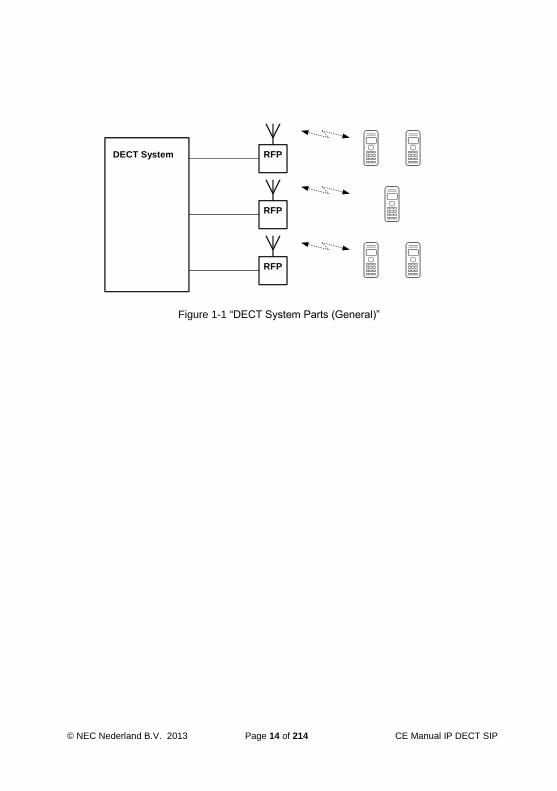
DECT System RFP
RFP
RFP
Figure 1-1 “DECT System Parts (General)”

CE Manual IP DECT Page 15 of 214 © NEC Nederland B.V. 2013
PBX
RFP
RFP
RFP
DECT
System
IP
Based
Note: This figure shows a general system setup.If applied to NEC IP DECT configuration, the:
DECT System IP Based = DAP ControllerPBX= PBX type that is supported by NEC IP DECTRFP = DAP (DECT Access Point)
Figure 1-2 “DECT System Parts in an IP Solution as Add-on to a PBX”
The radio area covered by a single RFP (DAP) is called a cell. The RFPs (DAPs) are
located so that the cells overlap slightly and the PP can remain in contact with the DECT
system when moving from one cell to another. A group of cells belonging to one DECT
system is called a cluster. According to the DECT standard, the maximum number of
simultaneous calls per RFP can be 12. (The DAP in the Business Mobility IP DECT
supports up to 12 simultaneous calls, depending on licenses.)
The number of RFPs (DAPs) needed to cover a certain area (within which the mobile
telephone users might roam) depends on many factors such as:
The size of the area.
The nature of the area:
The number and the size of buildings in the area.
The radio propagation characteristics of the building(s).
Materials used for walls, floors, elevator shafts, reinforced glass, doors etc.
Strong magnetic fields in the area (e.g. as result of welding equipment, radar, etc.).
The amount of telephone users in an area, and how often they make or receive calls.

© NEC Nederland B.V. 2013 Page 16 of 214 CE Manual IP DECT SIP
The speech signal through the air will be encrypted, if the portable handset allows it, to
ensure the privacy of the conversation. This encryption is done fully automatically, without
the intervention of a technician.
1.2 RFP-PP Communication
The radio link between the RFP and a PP can carry information on any one of ten carrier
frequencies and in one out of twelve pairs of time slots (12 in each direction). The ten
carrier frequencies are separated by 1728 kHz. The frequency range depends on the
region where DECT is used:
1880 MHz - 1900 MHz for European countries
1910 MHz - 1930 MHz for Latin America region
1900 MHz - 1920 MHz for China
1920 MHz – 1930 MHz North America (lower transmission power, –3 dB)
The modulated date rate is 1152 kb/s. DECT uses in the OSI physical layer the following
multiplexing techniques:
FDMA (Frequency Division Multiple Access);
TDMA (Time Division Multiple Access);
TDD (Time Division Duplex).
The RFP-PP communication radio signal carries time division multiplexed frames; each
frame is 10ms long. Each frame contains 12 time slots which carry data from RFP to the
PPs, and 12 time slots which carry data from PPs to the RFP. This means that two time
slots in every frame are needed for a full duplex connection to a PP. See Figure 1-3 “Carriers and Timeslots in the DECT Air Interface”.
0 1 2 3 4 9 10 11 12 13 14 15 16 21 22 23
F1
F10
10 ms frame
12 timeslots RFP to PP 12 timeslots PP to RFP
Figure 1-3 “Carriers and Timeslots in the DECT Air Interface”
Each time slot may carry 32 kbs Adaptive Differential Pulse Code Modulated (ADPCM)
speech/user data. Each time slot pair can contain ADPCM speech/user data on any one
of the ten carrier frequencies so that the RFPs carrier frequency often needs to be

CE Manual IP DECT Page 17 of 214 © NEC Nederland B.V. 2013
changed between time slots: Refer to Figure 1-4 "Each time slot can use any of the 10 Carrier Frequencies". The information within the time slot does not completely fill
the time slot; time is allowed for propagation delays, ramp up and ramp down of the
transmitter and for switching of the carrier synthesizer between slots.
0 1 2 3 4 5 6 7 8 9 10 11 12 13 14 15 16 17 18 19 20 21 22 23
F2 F7 F5 F2 F9 F3 F6 F8 F4 F6 F2 F7 F2 F7 F5 F2 F9 F3 F6 F8 F4 F6 F2 F7
Timeslot
Frequency
10 ms frame
12 timeslots RFP to PP 12 timeslots PP to RFP
Where F2 = carrier frequency 2, etc.
Figure 1-4 "Each time slot can use any of the 10 Carrier Frequencies"
A PP can use any of the 12 time slots (in each direction) on any of the 10 frequencies for
a full duplex connection. So a maximum of 120 full duplex channels are available for
connections to the PPs, within a cluster of a micro-cellular DECT system. In fact, this is
only possible under ideal conditions; no disturbance, no interference, no other channels
used, etc. Normally the conditions are not ideal in office or factory buildings, but the
number of channels available will still be more than sufficient.
Note that there is always a fixed relation between the downstream timeslot number (from
RFP to PP) and the upstream timeslot number (from PP to RFP) in one connection:
Upstream timeslot number = downstream timeslot number +12.
Upstream and downstream timeslot in one connection use always the same carrier
frequency.
1.3 Beacon Signal
1.3.1 General
The beacon signal is a signal which is transmitted by an RFP in case the RFP is idle (no
active calls).
This beacon signal contains the System Identifier of the DECT System, the so called
PARI (Primary Access Rights Identifier) and the number of the RFP, the RPN (Radio Part
Number). By means of this information the PP recognizes to which system a signal
belongs, and whether it is subscribed to that system or not. When there is a call for a PP,
it also contains paging information.

© NEC Nederland B.V. 2013 Page 18 of 214 CE Manual IP DECT SIP
When the RFP is not idle (there is an active call via the RFP), the beacon signal
information is also transmitted in the call connection. Therefore, the beacon signal is not
necessary at an RFP which has one or more calls active. In the DECT application in the
Business Mobility IP DECT, there are two beacon signals transmitted per RFP (DAP)
when the RFP (DAP) is in idle condition. If there is a call only one beacon signal remains
active. When there are a number of calls via the RFP (DAP), no beacon signal is
transmitted anymore.
1.3.2 Beacon Signal and PP
When the PP is in idle condition (not involved in a conversation) it scans the environment
for the signals of a nearby RFP (DAP). It locks onto the best signal that can be found.
This signal can be a beacon or a channel which is used for a call, because such a
channel contains the beacon signal information.
The PP uses the signal to synchronize its timing with the central system, and then it
monitors the information transmitted via that RFP for calls to itself.
If the PP detects to many errors in the received signal (due to interference or weak signal)
the PP tries to find another better signal and locks onto another RFP.
In this way, the PP user can move around the area from cell to cell and remain in contact
with the DECT system via a radio link with a very good quality.
1.4 Call Handling Procedures between PP and RFP
1.4.1 Setting up a Call
In case the PP user wants to make a call, he/she goes off hook. The PP selects an
unused channel at the RFP to which it is locked. This channel is in one of the timeslots (0
... 11) from RFP to PP; for the communication from the PP to the RFP, the corresponding
timeslot is selected in the timeslot range 12 ... 23. This results in a full duplex connection
via the air. The connection setup goes through this RFP via the Business Mobility IP
DECT system to the SIP Proxy. (The voice connection is setup between the RFP/DAP
and the SIP User Agent.)
1.4.2 Paging and Answering a Call
If a PP is locked to a system, it continuously scans the beacon signal for paging
information. (This beacon signal can be part of an existing call or as standalone beacon.)
If the PP recognizes its own address in the paging data, it selects an unused channel at
that RFP to answer the call. This channel is in one of the timeslots (12 ... 23) from PP to
RFP; the RFP uses the corresponding timeslot (0 ... 11) from RFP to PP to communicate
with this PP. After the setup of the channel/bearer has been successful, the handset
starts alerting the mobile user. The user presses the "off-hook" key to answer the call.
Then the speech path is opened via the bearer that has already been setup.

CE Manual IP DECT Page 19 of 214 © NEC Nederland B.V. 2013
1.4.3 Encryption
Most portable sets are capable of encryption and so the user data is encrypted over the
air interface. This ensures the privacy of the conversation. Encryption is a process by
which the digitised speech is "scrambled" making it impossible for anyone monitoring the
frequency to listen to the conversation. For this scrambling, a DCK (DECT Ciphering Key)
is used. This is a key which is agreed at the first time data has been transferred between
the PP and the RFP (the moment that the PP "locks" to the DECT system).
1.5 Cluster Arrangement
1.5.1 General
A cluster is defined as a logical group of radio cells belonging to one DECT system.
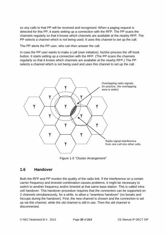
Within this arrangement bearer handover is possible. Figure 1-5 "Cluster Arrangement"
shows an ideal cluster arrangement of radio cells in which each cell has a boundary with
a number of other cells. An omnidirectional radio signal is transmitted equally in all
directions so that the actual radio signal from the RFP in cell 1 overlaps slightly into cell 2,
cell 3, cell 4, and so on. Similarly, the radio signal from the adjacent cells overlap into cell
1. So, cell 1 can be seen as the centre of a cluster of cells. If a certain frequency is used
in a certain timeslot in cell 1, it cannot be used in any of the adjacent cells in the same
timeslot because of interference at the cell boundary. But that same frequency can be
used in cell 8.
Thus, within a cluster a certain channel/frequency combination can be used again,
simultaneously, only if the cell which uses such a combination does not interfere with
another cell which uses the same combination.
1.5.2 RFP Behaviour in a Cluster
Each RFP constantly scans the area for signals in each channel. These signals can be
generated by other RFPs or other equipment. The RFP selects one or two free channels
to transmit the beacon signal. (The number of beacon signals depends on the number of
active calls via the RFP.)
1.5.3 PP Behaviour in a Cluster
The PP also picks up all sorts of signals which may come from the closest RFP, the next
cell or from outside equipment. It locks onto a good RFP signal, and when it must make or
receive a call it chooses a channel with the least interference to do this.
When a call is made to a portable telephone then that telephone must be paged. This
means that all RFPs transmit a paging message. The information in each active timeslot
transmitted by the RFP contains paging data, whether it is in use for a connection or
being used only as a beacon. If an idle PP is locked onto a beacon it examines the
signalling data in that signal for paging data. Thus, it always receives all paging requests,
© NEC Nederland B.V. 2013 Page 20 of 214 CE Manual IP DECT SIP
so any calls to that PP will be received and recognized. When a paging request is
detected for this PP, it starts setting up a connection with the RFP. The PP scans the
channels regularly so that it knows which channels are available at the nearby RFP. The
PP selects a channel which is not being used. It uses this channel to set up the call.
The PP alerts the PP user, who can then answer the call.
In case the PP user wants to make a call (own initiative), he/she presses the off-hook
button. It starts setting up a connection with the RFP. (The PP scans the channels
regularly so that it knows which channels are available at the nearby RFP.) The PP
selects a channel which is not being used and uses this channel to set up the call.
Overlapping radio signals.(In practice, the overlapping area is wider)
Radio signal interference from one cell into other cells.
Figure 1-5 "Cluster Arrangement"
1.6 Handover
Both the RFP and PP monitor the quality of the radio link. If the interference on a certain
carrier frequency and timeslot combination causes problems, it might be necessary to
switch to another frequency and/or timeslot at that same base station. This is called intra-
cell handover. This handover procedure requires that the connection can be supported on
2 channels simultaneously, for a while, to allow a "seamless handover" (no breaks and
hiccups during the handover). First, the new channel is chosen and the connection is set
up via this channel, while the old channel is still in use. Then the old channel is
disconnected.

CE Manual IP DECT Page 21 of 214 © NEC Nederland B.V. 2013
If the mobile user roams from one cell to another, during the conversation, he goes
probably out of range of the first RFP and into the range of the second. In that case, when
the quality of the transmission requires it, the radio link switches over to the new RFP.
This is called inter-cell handover. Once again it is a seamless handover.
Note: A handover is always initiated by the PP!
1.7 Call Quality Control
Both the RFP and the PP monitor the quality of the call.
If the PP decides that the quality is not acceptable, it can do one of three things:
Request that the RFP uses its other antenna to communicate with the PP. The signal in the cell may suffer from fading, so that at one place the signal might be poor while very close to it the signal may be acceptable. To counteract this, each RFP has two antennas mounted close together. The system tries to select the best antenna for each channel separately. This method of using two antennas is referred to as antenna diversity. If the quality of the connection warrants it, the PP can request a handover to another channel. That channel may be on the same RFP (intra-cell handover) or on another RFP (inter-cell handover). During handover, the communication to the PP is built up over the new channel so that for a short time the communication is available over both the old and the new channel. Then the old channel is disconnected. The user does not notice any break in the communication due to handover. Mute the output (voice connections). It blocks the stream of information from radio signal to user (ear piece, in a telephone). This stops noisy signals being passed on to the user. It is done as a temporary measure, only. Note that muting is done on both ends of the connection independently.
If the RFP decides that the quality of the connection to a certain PP is not acceptable it
can do one of three things:
Use the other antenna (antenna diversity). The PP does not notice the change. Tell the PP that a handover is necessary. The PP always initiates the handover after selecting the best channel as seen from the PP. It can temporarily block the data stream from PP to the SIP Proxy. (Note that muting is done on both ends of the connection independently.)
1.8 Subscription and De-Subscription
Before a PP can be used, it must be subscribed (registered) to the system. That means
that a relation must be defined between the DECT System and the PP. There are three
identifiers used to define the relation between the system and the PP:
IPUI (International Portable User Identity)
This is the identity number of a PP. It is issued from the system to the PP during

© NEC Nederland B.V. 2013 Page 22 of 214 CE Manual IP DECT SIP
subscription. From that time onwards, the PP is recognized by the system at its IPUI.
This number is a unique number in the system, there is no other PP with the same
IPUI.
PARK (Primary Access Rights Key), PARI (Primary Access Rights Identity), SARI (Secondary Access Rights Identifier)
The PARI is a worldwide unique identifier for an individual DECT system. When
stored in the handset, it is called the PARK. A DECT system can transmit a second
"ARI" (Access Rights Identifier), called the SARI. The SARI is explained in Section
1.9 “Secondary Access Right Identifier (SARI)”. The unique DECT system identifier
(PARI, and sometimes also the SARI) is delivered on a certificate, together with the
system. It must be entered in the system manually.
UAK (User Authentication Key)
This is a secret key which uniquely defines the relation between the PP and the
DECT system (PARI or SARI)
DECT SystemRFP
PARI (SARI), UAK IPUI, UAK, PARK
Figure 1-6 "UAK Relation between the IPUI and the PARI"
When a PP is subscribed (made known) to a DECT system, the relation between the
PARI of the DECT System and the IPUI of the PP is defined, see Figure 1-6 "UAK
Relation between the IPUI and the PARI". The PARI is stored in the PP as PARK, the PP
gets a unique identifier (IPUI) and a secret key (UAK) is assigned to the relation between
the PP and the DECT System. From now on the PP knows to which system (PARI) it is
subscribed. (In this section only the PARI is mentioned. For info on the SARI, consult 1.9
“Secondary Access Right Identifier (SARI)”.)
For the subscription procedure the WEB interface for Management must be used. This
WEB interface provides access to the configuration settings in the DAP
Controller/Manager, which is the Server that controls the DECT System. In the WEB
interface for DECT Management, one or more extension numbers can be created and
then selected to start the subscription procedure the (these) extensions (PP). Also one or
more existing extension number(s) can be selected to subscribe a handset to. Then the
DAP Controller/Manager generates a code ("PIN code" or also called "Authentication
Code") which is visible via the WEB Interface. This code must be entered in the PP within

CE Manual IP DECT Page 23 of 214 © NEC Nederland B.V. 2013
a certain time period. If the operation has been completed successfully, the PP is
subscribed to the system and is allowed to make and receive calls. (Assumed that the
handset is known and registered in the PABX as well.)
A portable can be subscribed to more than one DECT system. Therefore, it can be used
in areas covered by different DECT systems or in different areas with their own DECT
system. This allows you for example, to use the same PP for the DECT system which is
operational in your company and also for your home DECT. Also if the company is
located at different sites, it is possible to use the same PP at the different sites, if DECT
systems are present on these sites. It has a different extension number for each DECT
system. It cannot roam from one of these areas to the other, while busy with a
conversation. The user of the portable must ensure that his set is communicating with the
required DECT system, when making calls in a certain area. This may be done manually
by a selection key, depending on the type of the portable. There are also PPs which
selects DECT systems automatically.
The WEB interface for DECT Management can be used to de-subscribe ("terminate" or
"disable") the PP. Such a service condition of a PP can always be displayed at the WEB
interface for DECT Management.
A portable which has been "terminated", still contains the subscription data, but cannot
gain access to the system. (If the PP supports a "reset" and this is executed at the PP, the
subscription data in the portable is removed also.) The Administrator (user of the WEB
interface for DECT Management) can use the "terminate" command (remove
subscription) in case the portable has been lost or damaged.
A portable which has been "disabled" via the WEB interface for DECT Management has
been put on the blacklist in the DAP Controller/Manager. When the PP is or becomes
within reach of the radio signals, the DAP Controller/Manager and the PP exchange
information which results in the de-subscription of that PP. It is no longer recognized by
the DECT system and it is free to be subscribed again. This is the normal way to de-
subscribe a portable set.
If a portable has been disabled, but the DECT System cannot reach the PP and complete
the de-subscription, the "terminated" command can be used after the "disable" command.
1.9 Secondary Access Right Identifier (SARI)
The SARI (Secondary Access Right Identifier) has the same function as the PARI, but it is
used as a second identifier in case the PARI does not match between the DECT system
and the PP.
The PARI is a unique number belonging to one DECT system only. The SARI can be the
same identifier, used in more than one DECT system. The DECT system transmits both
PARI and SARI as identification signals.
If the PP detects a DECT signal in the air, it checks whether the PARI in that signal
matches with its own PARI data in the subscription record. If so, the PP "locks" to that

© NEC Nederland B.V. 2013 Page 24 of 214 CE Manual IP DECT SIP
signal. If not, the PP does a second check but now on the received SARI. If that matches,
the PP "locks" to that signal.
The Secondary Access Rights (SARI) is used in case you want to use your PP on more
than one DECT system (no handover possible between the systems!). The PP uses the
same subscription record (comprising the PARK, IPUI and UAK) in the handset for PARI
or SARI. For using a SARI, you must subscribe your PP to one system, and copy the
subscription record to other systems, all having the same SARI. You don't need to
subscribe that PP anymore to the other systems.
Figure 1-7 “Using SARI in three DECT Systems” gives an example of three different
DECT systems (three different PARIs) and one SARI. In this example the PP is
subscribed to the SARI of system X. This SARI is not unique because the other systems
have the same SARI. Therefore the subscription record can be copied from DECT
System X to the other DECT Systems. (The DECT Manager allows you to copy the
subscription record from one DECT System to another.) When the PP receives radio
signals from system Y or system Z, it first checks the PARI of that system and if that
doesn't match with its PARK it will do a check for the SARI of that system. The SARI
matches with the PARK in the PP, and because the subscription data was copied, the
UAK will also match. So, the PP can also be used on systems Y and Z.

CE Manual IP DECT Page 25 of 214 © NEC Nederland B.V. 2013
DECT System X
RFP
PARI = 100092B4SARI = 1000900A
Subscription record for extension number 400 on SARI = 1000900A
DECT System Y
RFP
PARI = 10009771SARI = 1000900A
Subscription record for extension number 400 on SARI = 1000900A
DECT System Z
RFP
PARI = 10009E35SARI = 1000900A
Subscription record for extension number 400 on SARI = 1000900A
Subscription record for extension number 400 on SARI = 1000900A
Figure 1-7 “Using SARI in three DECT Systems”

© NEC Nederland B.V. 2013 Page 26 of 214 CE Manual IP DECT SIP
2 DECT IN IP NETWORK
2.1 System Architecture
The implementation of IP DECT is as a standalone system that is connected to a PBX (SIP registrar and SIP Proxy) via a TCP/IP connection carrying the SIP (Session Initiation Protocol) protocol. This means that in the PBX, the DECT extensions will be assigned as SIP extensions. From the PBX perspective, there is no difference between a SIP extension and an IP DECT extension.
In Figure 2-1 "Business Mobility IP DECT - System Configuration" you see the general
configuration of the Business Mobility IP DECT system in an SIP Proxy configuration.
Figure 2-1 "Business Mobility IP DECT - System Configuration"

CE Manual IP DECT Page 27 of 214 © NEC Nederland B.V. 2013
DAPs
The DAP (DECT Access Point) is the actual DECT transmitter/receiver. There are
three generations of DAP types: AP200, AP300 and the AP400. The AP400 series is
the latest model.
All DAP Types support up to 12 simultaneous calls. For the AP400, functionality
licenses are applicable.
The DAPs are powered via the Ethernet interface (PoE).
Besides radio traffic, the DAPs take care of subscription control and call control data
handling to/from the SIP Proxy.
The AP200S, AP300, AP300C, AP400 and AP400S/C are equipped with internal
antennas. For all types, there is a version that supports connecting external
antennas: the AP200E, AP300E and the AP400E.
DAP Controller/Management Computer
The DAP Controller/Manager performs the following main functions:
WEB Server for management (based on IIS = Internet Information Services)
Distribution of subscription data over the DAPs.
Firmware Uploading to handsets
Collecting Subscription data
Low rate messaging Services
Controlling the IP DECT system in case there are Branch Office location.
Besides the items mentioned above, the DAP Controller software comes with a
Configurator, to setup the IP DECT Configuration.
When the Business Mobility IP DECT system is up-and-running and management
actions are not needed, the DAP Manager can be disconnected and is not needed
anymore, except for the following functions.
Business Mobility IP DECT configuration with branch offices.
Low Rate Messaging Services (LRMS).
Maintenance
Collecting diagnostic data
SIP Proxy
The SIP Proxy Server (PBX) accepts session requests made by a SIP UA (User
Agent). The UA in this configuration is the user that is subscribed to the IP DECT
system, or any other SIP phone. When the SIP Proxy receives a call requests it will
normally consult the SIP Registrar server to obtain the recipient UA’s addressing
information. The SIP Proxy can be combined with the SIP Registrar.
SIP Registrar
The SIP Registrar server (PBX) contains a database with the address information of
all User Agents in the SIP domain. The Registrar server receives and sends UA IP
addresses and other pertinent information to the SIP Proxy server.
© NEC Nederland B.V. 2013 Page 28 of 214 CE Manual IP DECT SIP
Note: The SIP Registrar and SIP Proxy are logical “roles” in the SIP structure that can
be played by separate devices but also by one device. For the purpose of clarity,
in the figures in this chapter the two roles are depicted on separate devices.
Note: In this manual you will only see the SIP Proxy server and the SIP Registrar server
and no other SIP servers like a SIP Redirect server or SIP Location server. The
reason for this is that the IP DECT system (holding the SIP UA’s) communicates
with the SIP Proxy and SIP Registrar and not to other SIP server types. The other
SIP servers work on a different level in the SIP configuration.
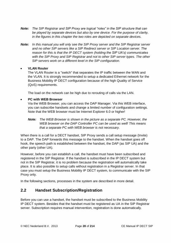
VLAN Router
The VLAN Router is a "switch" that separates the IP traffic between the WAN and
the VLAN. It is strongly recommended to setup a dedicated Ethernet network for the
Business Mobility IP DECT configuration because of the high Quality of Service
(QoS) requirements.
The load on the network can be high due to rerouting of calls via the LAN.
PC with WEB Browser
Via the WEB Browser, you can access the DAP Manager. Via this WEB interface,
you can subscribe handsets and change a limited number of configuration settings.
Note that the WEB browser must be Internet Explorer 6.0 or higher!
Note: The WEB Browser is shown in the picture as a separate PC. However, the
WEB browser on the DAP Controller PC can be used as well! This means
that a separate PC with WEB browser is not necessary.
When there is a call for a DECT handset, SIP Proxy sends a call setup message (Invite)
to a DAP. The DAP forwards this message to the handset. When the handset goes off
hook, the speech path is established between the handset, the DAP (as SIP UA) and the
other party (other UA).
However, before you can establish a call, the handset must have been subscribed and
registered in the SIP Registrar. If the handset is subscribed in the IP DECT system but
not in the SIP Registrar, it is no problem because the registration will automatically take
place. It is also possible to setup calls without registration in a Registrar server. In that
case you must setup the Business Mobility IP DECT system, to communicate with the SIP
Proxy only.
In the following sections, processes in the system are described in more detail.
2.2 Handset Subscription/Registration
Before you can use a handset, the handset must be subscribed to the Business Mobility
IP DECT system. Besides that the handset must be registered as UA in the SIP Registrar
server. Subscription requires manual intervention, registration is done automatically.

CE Manual IP DECT Page 29 of 214 © NEC Nederland B.V. 2013
Figure 2-2 “Phases in the Subscription Process” shows the phases in the subscription
process.
Figure 2-2 “Phases in the Subscription Process”
The following phases are distinguished in the subscription process.
The administrator starts a subscription process via the DECT Manager WEB page. This WEB page is accessible from a WEB browser in the network. The administrator “enables” a subscription, which means that the subscription process is started. The Business Mobility IP DECT System is now waiting for action from a handset. Now the subscription must be executed from the handset. The handset user must enter the PIN code that is displayed on the DECT Manager WEB page. When the PIN code is entered on the handset, the subscription record is created in the DAP Manager Database. The DAP Manager will distribute the subscription data to one of the DAPs. Distribution has the following characteristics:
The DAP Manager tries to distribute the subscription records equally over the DAPs.

© NEC Nederland B.V. 2013 Page 30 of 214 CE Manual IP DECT SIP
The maximum number of subscription records per DAP is 25.
Once a subscription record is stored into a DAP, it will normally not be moved to another DAP anymore. There are two exceptions on this: If you “Delete” a DAP manually from the DAPs list in the DECT Manager, the subscription records of that DAP will be distributed over the remaining DAPs. If the handset moves to/from a branch office, the subscription record moves with the handset to/from the branch office. Moving subscription between main site and branch office(s) is activated when the handset does a “location registration” in the main site or branch office. Note that the DAP Manager must be active to make this moving possible.
If DAPS are connected in a Branch office, the Branch office is regarded as a subscription island. The subscription record for a handset is either in a DAP at the main site or in a DAP at (one of) the branch office(s). When a handset executes a “location registration” at the main site or one of the branch offices, the subscription record is moved to the island where the location registration was done.
The DAP sends a SIP Register to the SIP Proxy/Registrar to register itself as a SIP extension (UA)
After the subscriptions are executed, each DAP contains a number of subscription
records. The DAP Manager contains subscription data of all handsets in the system. If the
DAP Manager is disconnected, the system remains operational.
The subscription records in the DAPs are stored in Flash Memory.

CE Manual IP DECT Page 31 of 214 © NEC Nederland B.V. 2013
Figure 2-3 “Subscription locations”
2.3 Automatic Distribution When DAP Down
When a DAP goes down, the subscription records in that DAP are not accessible
anymore, and therefore, the associated handsets cannot be used anymore. However, the
subscription records of a broken DAP are automatically distributed over other DAPs after
10 minutes down time. This time is adjustable; the shortest time is 5 minutes.
This automatic distribution requires that the DAP Manager must be up and running. If not,
automatic distribution does not take place!
When you connect the DAP Manager after a DAP went down, the timer starts from the
moment that the DAP Manager is up and running. This means that you can replace the
faulty DAP with a new one, with moving the original subscriptions to the new DAP within
those 10 minutes. This time is configurable.

© NEC Nederland B.V. 2013 Page 32 of 214 CE Manual IP DECT SIP
2.4 Handset Registration in SIP Registrar
DECT Handset registration means that a DECT Handset makes itself know to the SIP
Registrar. This information is needed to store relation between the extension (UA) number
and its IP address and/or the full computer/device plus domain name. The Registrar holds
a database containing the data of all UAs that are registered in the (local) domain.
Registration data can be stored for a limited time period only, which is by default 3600
seconds. This time period is issued to the Registrar server. The Registrar server normally
accepts this time period, but may also change the time period. The Registrar tells the
Business Mobility IP DECT system the stored time period (in the “ACK” message). When
the time expires, the registration is removed from the Registrar. However, the Business
Mobility IP DECT system knows when the timer expires and will execute a register again.
An IP DECT handset registers its number:
at subscription
when the DAP holding the subscription record of an extension (UA) starts up
with an interval of 1 a minute up to 25 minutes (depending on the number of
subscriptions in the DAP.
Note: Note that it is not always necessary to do a registration to a Registrar service.
Depending on the SIP servers configuration and the SIP Proxy type, registration
can be done implicitly via a call setup (INVITE) request from the UA to the SIP
Proxy. In that case no Registrar server is used and no registration expiry timer is
used.
Note: The registration takes place between the DAP where the subscription record of
the handset resides and the SIP Registrar. So, the handset does not have an IP
address and the handset does not contact the SIP Registrar directly.
2.5 Handover Mechanism
The handover mechanism ensures seamless handover from one DAP to the other DAP in
a multi DAP (radio) environment. So in other words, when a handset is in an existing
voice call, it can move between the DAPs without losing the connection or hearing a click.
In Figure 2-4 “Call connection before handover” a call is depicted between a SIP IP
telephone and a DECT handset with extension number 200. The speech path is a peer-
to-peer VoIP connection between the SIP IP extension and a DAP.

CE Manual IP DECT Page 33 of 214 © NEC Nederland B.V. 2013
Figure 2-4 “Call connection before handover”
However, handset 200 moves from one DAP to another DAP. See Figure 2-5 "Handover
action started". The handset searches for a better radio signal, and detects that the
second DAP has a better signal. The handset issues a request for handover to the new
DAP. However, the new DAP does not know where the existing voice connection to
handset 200 resides so it issues a multicast request for searching previous connection to
handset 200 over the network with DAPs. The original/first DAP responds to this request
because the call was initially be set up via this DAP.

© NEC Nederland B.V. 2013 Page 34 of 214 CE Manual IP DECT SIP
Figure 2-5 "Handover action started"
Now the connection is copied from the original/first DAP to the second/new DAP. See
Figure 2-6 "Handover taken place, new connection active". The original/first DAP will
release the radio connection to the handset and the new connection remains in place.
Note that the original connection is not removed from the original DAP, but this DAP
"relays" the connection to the second DAP. The original DAP cannot release the IP voice
connection, because the IP voice connection between the SIP IP extension and the DAP
4 is established, based on a combination of sockets. This combination is fixed during the
connection.

CE Manual IP DECT Page 35 of 214 © NEC Nederland B.V. 2013
Figure 2-6 "Handover taken place, new connection active"
Note: When a second handover takes place from DAP 2 to DAP 3, DAP 1 will setup a
second relay to DAP 3 and REMOVES the relay to DAP 2. So the maximum
number of relayed RTP streams per call in the network is 1.
2.6 Is DAP Manager Required?
The DAP Manager is not required for call handling. A simple Business Mobility IP DECT
system will therefore look like Figure 2-7 "Simple Business Mobility IP DECT configuration
without DAP Manager”.

© NEC Nederland B.V. 2013 Page 36 of 214 CE Manual IP DECT SIP
Figure 2-7 "Simple Business Mobility IP DECT configuration without DAP Manager”
The subscription data is stored in the DAPs.
The DAP Manager is temporary needed in the following cases:
During installation
During installation the DAP Manager is needed to enter licence information,
extension numbers, to subscribe handsets etc.
Management
For any system management action the DAP Manager is needed
Replacing a DAP
When you replace a DAP be aware that it may contain subscription data. Therefore,
you need to open the DAP Manager WEB interface and execute a delete DAP. Then
the subscription data that was in this DAP is put into the remaining DAPs. If you put
a new DAP in place, initially it will not contain subscription data. Only after executing
a subscription procedure, it may contain subscription data.

CE Manual IP DECT Page 37 of 214 © NEC Nederland B.V. 2013
Note: Be aware of the fact that in a number of system configurations, the DAP Manager
is always needed.
In the following cases, the DAP Manager is always needed:
Branch office configuration
If your Business Mobility IP DECT system comprises a Main site and one or more
branch offices over a router using unicast, these DECT islands require the DAP
Manager for automatically moving subscription data when a handset moves from
one island to another (island = main site or (one of) the branch office(s)). The DAP
Manager is not necessary for call handling.
Also the DAP Manager is needed for backup of subscription data. If there are branch
offices in the DAP Controller configuration, the subscription records are stored in
RAM in the DAPs. If a DAP goes down and starts up again, the DAP will get the
subscription data from the DAP Manager! If there are NO Branch office DAPs the
subscription data is stored in FEPROM in the DAPs. In that case, the DAP Manager
is not needed as subscription database.
Low Rate Messaging Service (DECT Messaging)
DECT Messaging always require the DAP Manager.
Sending alarm e-mails or sending SNMP traps
The DAP Controller is capable of sending an e-mail when a DAP goes down, or a
predefined threshold of channel occupation is exceeded or when the DDS service in
the DAP Controller goes down. Also it can send an SNMP trap in case of one of
these events (for more info, consult the Advanced Data manual).
Collecting diagnostic data
The DAP Controller can collect detailed diagnostic and performance data. This
automatically enabled when the DAP Controller is up and running.
2.7 Radio Synchronization
2.7.1 How it Works
The radio network structure supports seamless handover of existing calls. This means
that when there is a call, and the handset moves from one radio to another, that other
radio should take over the call. The call may not be interrupted and the user may not hear
any click or what so ever. If the handset needs to re-synchronize to the other radio, then
the user will hear at least a click. So, supporting handover requires an accurate
synchronization of the radio signals in the air. How is this achieved?
Synchronization cannot take place via the cabling structure, because Ethernet does not
allow transport of synchronous data, or in other words, the timing of data sent via Ethernet
is not accurate enough. Therefore synchronization must go via the air.

© NEC Nederland B.V. 2013 Page 38 of 214 CE Manual IP DECT SIP
Figure 2-8 "Radio Synchronization"
A DAP (Radio) cell can be seen theoretically as a circle around the DAP. In Figure 2-8
"Radio Synchronization" you see two circles around the DAP: one in which you have
sufficient radio signal strength for a good voice quality, and another (wider) circle with
sufficient signal strength for synchronization. Due to the cellular structure of a DECT
Radio Network, there must always be overlap in the cells with sufficient voice quality. The
wider cell limit around the DAP will therefore have quite some overlap with the other cell,
and will reach to the radio of the other cell. This means that the DAPs of the overlapping
cells receive (weak) radio signals of each other. However these radio signals are still
strong enough for synchronization purposes.
The receiving DAP checks the radio signals on PARI, to make sure that it belongs to the
same DECT system. If they belong to the same DECT system, the DAPs will synchronize
with each other according to predefined rules.
The DAPs are always transmitting via a minimum of two bearers. If there are no voice
calls via a DAP, the DAP will transmit two dummy bearers. If there is one or more voice
calls via the DAP, there will be one dummy bearer plus the voice call(s).
2.7.2 Synchronization Hierarchy
When DAPs try to synchronize to each other, there must be a hierarchy structure. One or
more DAPs must be assigned as synchronization source. The system arranges this itself,
and under normal conditions you don't need to do anything. However, if you have a
complex DAP cell structure, manual intervention might be needed.

CE Manual IP DECT Page 39 of 214 © NEC Nederland B.V. 2013
When a DAP is started up, it will try to synchronize to a DAP in the environment. Each
DAP has its own unique identifier, the RPN (Radio Part Number). The RPN is a
hexadecimal two digit number. A DAP will always try to synchronize to a DAP that has a
lower RPN.
Figure 2-9 "Synchronization Structure"
In Figure 2-9 "Synchronization Structure" you see an example of a simple DAP structure.
When the system starts up, the DAPs try to synchronize to the DAP with the lowest RPN.
For DAP 010 it means that it will become the synchronization source! The DAPs with
RPNs 011, 013 and 014 will synchronize to RPN 010. However, RPN 012 will synchronize
to RPN 013 although RPN 013 is a higher number. Finding a synchronization source is
not limited to one level deep only. DAP 012 knows that DAP 013 is synchronized to a
DAP (010) that has a lower number than itself. Therefore DAP 012 will synchronize to
DAP 013, because it is aware that DAP 013 gets its source from a DAP with a lower
number.
If a DAP "sees" more than one other DAPs, the DAP will synchronize to the DAP that has
the shortest path to the synchronization master. If the path to the master is the same
number of hops for more DAPs, the DAP will synchronize to the DAP with the lowest
RPN.
It is possible that there are more than one "synchronization islands" in the system. In that
case, each synchronization island has its own synchronization master. The
synchronization algorithm is applicable for each individual island.

© NEC Nederland B.V. 2013 Page 40 of 214 CE Manual IP DECT SIP
The DAP Controller keeps track of the synchronization structure. Note that the RPN
number that the DAPs have, are assigned once, when they start up after installation. The
DAP that reports itself at first will get the lowest number, which means that it will become
the source for providing the synchronization to the DAP network structure.
If you want to make a DAP a synchronization master, or give a DAP a higher position in
the synchronization structure, you can assign a lower RPN number to a DAP manually.
RPNs can be assigned manually via the DECT Manager WEB interface.
The automatically assigned RPNs start at:
010
The automatic assignment of RPNs starts at 010 when the IP DECT system is setup
as Distributed DAP Controller.
Manually assigned numbers can be in the range 000 . . . 00F.
After the numbers are assigned at the first time start up, these numbers are stored in a file
in the DAP Manager and will not change anymore, even after system start-up.
2.7.3 Coverage and Signal Strength Calculation
Synchronization between DAPs requires sufficient radio signal strength between DAPs.
The following items are relevant for the signal strength for synchronization.
To achieve a good voice quality, the minimum signal strength at the receiver in the
handset and DAP, must be -72 dBm. (This includes a margin of -10 dBm for fast
fading -dips.)
Synchronization is possible if the strength of the received signal from another DAP is
-80 dBm ... -85 dBm (this is adjustable).
In open area, the distance is doubled if the received signal strength is 6 dB lower.
This means that at a minimum signal strength for good voice quality of -72 dBm and
a distance “X”, the signal strength at the double distance (2X) is -78 dBm. See
Figure 2-10 "Signal Strength Considerations".

CE Manual IP DECT Page 41 of 214 © NEC Nederland B.V. 2013
Figure 2-10 "Signal Strength Considerations"
In open area there is more than sufficient signal strength for synchronization. The
expected level at the double distance is -78 dBm. The required level is -80 dBm ... -
85 dBm. This leaves a safely margin of 2 ... 7 dB.
In practice there can be and will be objects in between the DAPs which may
introduce some loss. However, there are also (many) objects that causes reflections,
which means that the signal will reach the DAP via other paths as well with sufficient
signal strength. Real life installations have proven this theory.
The error rate in the received frames can be much higher than for speech. (50%
frame loss is still acceptable).
Practice has indicated that coverage measurements for traditional DECT can also be
applied for Business Mobility IP DECT.
2.8 IP Port Number Assignments
IP Port Numbers are assigned for a speech connection. They are assigned per session,
and then released again.
In the DAP Controller, there is a predefined "pool" of IP port numbers. This is specified in
file dapcfg.txt. You can access the data is this file using the DAP Configurator tool
(see chapter 9 “CONFIGURATION - DAP CONFIGURATOR TOOL”) and adapt the port
number range to your wishes.

© NEC Nederland B.V. 2013 Page 42 of 214 CE Manual IP DECT SIP
2.9 DAP Characteristics
2.9.1 General
The following DAP types exist:
AP200 Series, till November 2010
AP300 Series, from November 2010 till February 2013
AP400 Series, current AP400 version(from February 2013 onwards)
All of these DAPs share common characteristics. These characteristics are described in
section 2.9.2 “Common Characteristics”.
Type dependant characteristics are given in the following subsections.
2.9.2 Common Characteristics
Features
Note: The following list contains features that are only supported if the PBX
supports it at well.
DECT GAP and CAP compatible.
DECT Seamless handover.
DECT Low Rate Messaging Service (LRMS) (Max. number of characters depends on the type of handset used.)
CLIP and Name Display.
Enquiry
Call Progress tones.
DTMF tones.
Message Waiting indication.
DAP Software downloadable.
Capacity
Max. number of simultaneous calls: 12 Please note that this maximum number of calls is only applicable when the DAP is synchronization source/master. If the DAP is not the synchronization master, the maximum number of simultaneous calls is 11. Also note that the maximum number of simultaneous calls per DAP is also limited by licenses in a licensed version of IP DECT.
Max. number of simultaneous relay calls: 12
Max. number of DAPs per network: 256
Max. number of DAPs with DAPs in Branch Offices: 750
Max. number of simultaneous calls per network with 256 DAPs: 11 x 255 +12 =2817. This depends on the network configuration and available DAP channels.
IP Interface Characteristics
100 Base-T Full duplex, full support of auto-negotiation in Ethernet Switch

CE Manual IP DECT Page 43 of 214 © NEC Nederland B.V. 2013
Maximum cable length according to the IEE802.3 specification (100 meters).
Audio Coding: G711
DTMF generation: H.245
Call control protocol: Proprietary.
IP protocols: DHCP and TFTP
Environmental Conditions
Storage temperature range: -25º to +55º Celsius
Operational temperature: 0º to +40º Celsius
Note: The operational temperature range is 0° to 40° Celsius. When you use a
DAP outdoors, there is an outdoor box available that will increase the
temperature range. Please contact your supplier for more information.
2.9.3 AP200 Characteristics (not available anymore)
The AP200 is the General release of the DAP for the Radio Traffic. It complies with all
characteristics mentioned in section 2.9.2 “Common Characteristics”. In addition to that it
supports G.729 (G.729AB).
2.9.4 AP200S (not available anymore)
The AP200S complies with the common characteristics as given in Section 2.9.2
“Common Characteristics”. The AP200S does not support G.729.
The AP200S must be used with the associated DAP Controller software Release 4 for
AP200S or with DAP Controller Release 5.
2.9.5 AP200E (not available anymore)
The AP200E is the same as the AP200 but allows you to connect external antennas.
When used in an AP200S configuration it behaves as if it is an AP200S.
2.9.6 AP300
The AP300 is described in the AP300 Customer Engineer Manual. Please consult the AP300 Installation Manual for more information:
Note: The AP300 and AP300E can be mixed with the AP200 and AP200S in the same
system. However, make sure that either all DAPs in the same system do support
G.729 or all DAPs do not support G.729. A mix is not allowed.
2.9.7 AP300E
The AP300E is the same as the AP300 but allows you to connect external antenna’s.
When used in an AP200S configuration it does not support G.729.

© NEC Nederland B.V. 2013 Page 44 of 214 CE Manual IP DECT SIP
2.9.8 AP400
This is the generic AP400, NEC branded.
2.9.9 AP400E
The AP400E is equipped with connectors to connect External Antennas.
2.9.10 AP400C
The AP400C is used for IP DECT with PBX type: IPC100/IPC500, XN120/Aspire,
SV8100, SL1000/1100
2.9.11 AP400S
Maximum of 4 x AP400S in one system with PBX type: IPC100/IPC500, XN120/Aspire,
SV8100, SL1000/1100 PBXs
2.10 AP200/AP200S Power Provision
An AP200 can be powered on two different ways:
Line powering
The AP200/AP200S supports Line powering according to specification IEEE802.3af.
It supports both versions: “phantom power” as well as “power over spare wires”.
The voltage at the patch panel should be between 42 Volts and 60 Volts.
Note that the distance depends on the cable type and the voltage at the patch panel.
External Power Supply
External Power supply connected to the Power Connector on the AP200. This power
supply should meet the following requirements:
AC/AC Power adapter
Secondary voltage: 40 V AC, +10%/-10%
Maximum power consumption: 10 Watts
2.11 AP300/AP400 Power Provision
The AP300/AP400 is powered via PoE. It supports Class detection. The AP300/AP400 is
a Class 2 device when used on PoE Switches. For more information consult the
AP300/AP400 Installation Manual.
2.12 More than 256 DAPS
IP DECT allows you to setup an IP DECT System with more than 256 DAPs. There are
two possibilities.

CE Manual IP DECT Page 45 of 214 © NEC Nederland B.V. 2013
System with Branch offices
Maximum number of DAPs per IP DECT system with Branch Offices is 750. Per
Main site or Branch Office, the maximum number of DAPs is 256.
This configuration can be setup with the standard IP DECT installation. For more
info, see Section 2.13 “RPN Number Ranges per Branch Office” and Section 10.5
System Configuration.
One IP DECT Cluster with seamless handover
Maximum number of DAPs per IP DECT System is 750, all on one location (Main
Site). Please note that this type of system is possible on “project” base and is not
part of the standard installation. For more information, please contact your IP DECT
supplier.
2.13 RPN Number Ranges per Branch Office
You can specify the range of RPN numbers that you want to use in the Head Quarter and
in the individual Branch Offices. That allows you to use up to 750 DAPs in one IP DECT
installation. Per Branch Office, the maximum number of DAPs is 256. Also in the Head
Quarter, the maximum number of DAPs may not exceed 256.
The Branch office DAPs are not allowed to “see” DAPs of other Branch Offices or the
Head Quarter.
Because the RPN number range is related to the Head Quarter or to Branch Offices, the
RPN number range is related to an IP network segment.
The DAP Configurator lets you set up the configuration in a very simple way, by means of
assigning RPN numbers to a Branch Office.
The RPN numbers in the DAP Manager exist of three digits instead of two. The RPN
number that is displayed in the handset (in special mode) consists of the two least
significant digits of the RPN number in the DAP Manager.
The configuration is stored in a file: bo_adm.txt.
© NEC Nederland B.V. 2013 Page 46 of 214 CE Manual IP DECT SIP
3 Licenses
3.1 General
From IP DECT Release 6.0 onwards, licenses are introduced for specific features. All
licenses have to be entered into the DAP Controller.
3.2 Functional Licenses
The following functional Licenses are available:
Maximum number of DAPs
You must have a license for the number of DAPs when licensing one of the
functional features listed here. Please note that the total number of DAPs that you
specify in this license, is the sum of license unities of 10 and 50 licences. E.g. when
you have 70 DAPs, you need one license for 50 DAPs and 2 licenses for 10 DAPs.
(1x50) + (2x10).
The maximum number of DAPs in a certain configuration is determined by the DAP
types. This can be:
4, in case of the AP400S system
256, in case of the AP400C and AP400E,
750 in case of the AP400, AP400G and the AP400E
For Future use: CAT-iq Data Licenses
Please note that this license is not yet available and is planned for future use.
Redundancy Central Site
This license is required to have a redundant DAP Controller configuration in the
Central site.
Branch Office Survivability
You need this license to allow Local DAP Controllers in one or more Branch Office
locations.

CE Manual IP DECT Page 47 of 214 © NEC Nederland B.V. 2013
Software Upgrade Allowance
To upgrade a Release 6.0 to a higher version, you need an Upgrade License. When
the license is activated, it provides a window of one month to install a higher version.
Please note that this license is made dependant on the system size. The steps are:
10 DAPs
50 DAPs
100 DAPs
256 DAPs
Please note that the total number of DAPs is the sum of the licences. E.g. when you
have 70 DAPs, you need one license for 50 DAPs and 2 licenses for 10 DAPs.
(1x50) + (2x10).
Messaging License.
Messaging is licensed in the DMLS and in the DAP Controller. Licenses are
exchangeable between the DMLS and the DAP Controller, so if you have a licence
for DMLS, you can import that license into the DAP Controller and vice versa. In the
DAP Controller, the license is related to the number of DAPs in the system and
should be the same number as specified in the first item in this list of licenses. For
more info on the Messaging License, consult Section3.6 DMLS Licenses.
Location Detection License, on top of the Messaging License.
This license is available on the DMLS and also in the DAP Controller. Licenses are
exchangeable between the DMLS and the DAP Controller, so if you have a licence
for DMLS Location Detection, you can import that license into the DAP Controller
and vice versa. The Location detection license is applicable for single point and
multipoint on the DMLS. When you order the license, you must order it on top of the
Messaging License. In the DAP Controller, the license is related to the number of
DAPs in the system and should be the same number as specified in the first item in
this list of licenses.
3.3 Project Based Licenses
There are a number of licenses that are only available on project basis. Further support is
required with these implementations.
Large Configuration License – Big Projects License
This license is required when your IP DECT system consists of more than 256 DAPs
in one cluster with seamless handover. This license requires a RAP (Risk
Assessment Procedure) and includes on-site support.

© NEC Nederland B.V. 2013 Page 48 of 214 CE Manual IP DECT SIP
Dual Band Mode – Cruise line license
This is a special license for IP DECT installations on cruise ships. This license
requires a RAP (Risk Assessment Procedure) and includes on-site support.
Reflection Cancelling.
This is a special license for IP DECT in environments with a lot of reflections. This
license requires a RAP (Risk Assessment Procedure) and includes on-site support.
ATEX (IECEx) License. .
This is a special license for the use of “intrinsic safe handsets” in environments with
a higher explosion risk.
ATEX = ATmospheres EXplosibles.
IECEx = International Electrotechnical Commission Explosive
3.4 System Assurance License
The system assurance license is a license to allow software upgrading from Release 6.0
to higher versions. The license is based on the number of DAPs. The license is already
mentioned in section 3.2 Functional Licenses
Note that there are two ways to get the Software Upgrade License:
By means of the NEC ordering tool.
By means of becoming a member of the System Assurance Program.
When the license is activated, it provides a window of one month to install a higher
version.
3.5 From Release 5 to Release 6
IP DECT Release 5 was license free, in IP DECT Release 6.0 and higher you can
continue to use features that were available in Release 5 but if you wish to use one of the
features listed in 3.2, 3.3 or 3.4 then you need an additional license for these various
functions and features.
When you upgrade from Release 5 to Release 6, the system will automatically generate a
license file with all the features that your system had in Release 5. So, you do not need to
have a license prior to upgrading.
CE Manual IP DECT Page 49 of 214 © NEC Nederland B.V. 2013
This license has the following characteristics:
It will cover all existing system configuration.
It is Free of Charge.
For new features, you must order a new license.
3.6 DMLS Licenses
From Release 6 onwards, the DMLS can be licensed in the DAP Controller License
mechanism. You don’t need a dedicated license for the DMLS anymore although if you
have a Release 5 DMLS license string you can continue to use this with your R6 system.
The DMLS license if used through a Release 6 license file is based on the number of
DAPs.
In the DAP Controller, there is a license for “DECT Messaging” and for “DECT Location
detection”. The Location Detection license is on top of the Messaging License.
There are two options to enable the DMLS Messaging/Location feature:
DMLS License String
When you already have a DMLS license string, you can use that license in the DMLS
and you can import that license string into the DAP Controller License mechanism by
means of the button “Add DMLS”. (See section 10.13.3 License Information
Window.). Please note that this is applicable for the Messaging license as well as for
the Location license.
DAP Controller License for Messaging and perhaps also Location detection.
When you have a license for Messaging or Location detection on the DAP Controller,
you can synchronize the DMLS application with it. The DMLS can retrieve the
license data from the DAP Controller license mechanism by means of one button.
When you have a “CTI license” for Messaging on the DAP Controller, you do not need to
have the Messaging license in the DAP Controller.
3.7 Where to Enter and Where to Find the License Data?
After ordering DECT licenses, you will receive a text file with the license data. You should
import that file into the DAP Configurator. In the DAP Configurator, you can also read out
the license information.
For more information on using the LMS to obtain your DECT licenses refer to the SV8100
Licensing Manual v2.0 on the SV8100 Technical DVD.

© NEC Nederland B.V. 2013 Page 50 of 214 CE Manual IP DECT SIP
For more information on using R6 licensing within the DAP Configurator, consult the
applicable sections in the chapter that describes the Settings:
Section 10.13.1 Install a new License File
Section 10.13.2 Reading out the Licenses
Section 10.13.3 License Information Window

CE Manual IP DECT Page 51 of 214 © NEC Nederland B.V. 2013
4 NETWORK CONFIGURATIONS
4.1 Typical Configurations
The IP DECT system must be implemented in a company infrastructure. As mind setting
tool, this chapter gives you four typical configurations with the advantages and
disadvantages. All configurations are based on using one IP DECT system (DECT
Cluster) in the network. You should consider which configuration you must implement at
the customer site. In the IP DECT Advanced Data Manual, you will find more information
about the system behaviour over a router, in chapter “System Behaviour over Router”.
Note: All IP switches that are involved must support IP multicast, with “IGMP snooping”
disabled.
Furthermore, disable “Spanning Tree Protocol” on ports that are used for DAPs
and set the switch ports to “fast forwarding”.
4.2 Simple Configuration
4.2.1 Network Configuration
Figure 4-1 "Example of Simple IP DECT network configuration" shows an example of a
simple configuration. All IP DECT devices are put in one subnet. This subnet is based on
one or more IP switches. If the switches serve more than one VLAN, all IP DECT devices
are put in one VLAN (therefore behaving as one subnet).

© NEC Nederland B.V. 2013 Page 52 of 214 CE Manual IP DECT SIP
Figure 4-1 "Example of Simple IP DECT network configuration"
The general characteristics of a simple configuration are as follows:
Seamless handover is supported between all DAPs.

CE Manual IP DECT Page 53 of 214 © NEC Nederland B.V. 2013
4.2.2 Settings in DAP Configurator
The DAP Configurator is described in Chapter 9. CONFIGURATION - DAP
CONFIGURATOR TOOL. However, in this section you will find an example of a setup for
a simple configuration.

© NEC Nederland B.V. 2013 Page 54 of 214 CE Manual IP DECT SIP
4.3 Branch Office Solution
4.3.1 Network Configuration
Figure 4-2 "Example of an IP DECT configuration with a Branch Office" shows an
example of a Branch Office configuration with a main office (head quarter) and two
Branch Offices. Main Office and Branch Offices are in different subnets connected via
routers. Routers can be connected over the WAN.
Figure 4-2 "Example of an IP DECT configuration with a Branch Office"
The general characteristics of an IP DECT configuration with Branch Offices are as
follows:
Allows interconnections with limited bandwidth between Head Quarter and Branch
office(s).
Allows interconnections with poor QoS between Head Quarter and Branch office(s).
(Radio Links, ADSL etc.)
No PBX needed in Branch Office(!).
Seamless handover is supported in Branch Offices and in Main Office.
No handset handover between Head Quarters and (individual) Branch Offices.
Head Quarter and individual Branch Offices must be in separate subnets (router(s)
needed).
No IP multicast support required for Routers.
Multicast TTL = 1, which means that IP multicast packages does not cross a router.

CE Manual IP DECT Page 55 of 214 © NEC Nederland B.V. 2013
4.3.2 Settings in DAP Configurator
The DAP Configurator is described in Chapter 9. CONFIGURATION - DAP
CONFIGURATOR TOOL. However, in this section you will find an example of a setup for
a Branch Office configuration.

© NEC Nederland B.V. 2013 Page 56 of 214 CE Manual IP DECT SIP
4.4 Routed Head Quarter
4.4.1 Network Configuration
Figure 4-3 "Example of an IP DECT Routed Head Quarter configuration" shows an example of a Routed Head Quarter configuration with a head quarter and two subnets connected via one or more routers. The subnets in the network are part of one company network.
Figure 4-3 "Example of an IP DECT Routed Head Quarter configuration"
The general characteristics of an IP DECT Routed Head Quarter configuration are as
follows:
Used for a Large Campus network that is split up into different (geographical)
subnets.
The network supports QoS and IP connectivity all over the Campus.
IP DECT configuration behaves as one large IP DECT system.
Full support of seamless handover between all DAPs in the IP DECT system.
Routers must support IP Multicast routing.
The IP Multicast address for IP DECT is the same in all segments.
Multicast TTL > 1, which means that the routers pass on the IP multicast packages.
In the IP DECT configuration, you must enter the subnet mask that is needed to
cover all networks (e.g. 255.255.252.0) for up to four subnets as in the previous
example.

CE Manual IP DECT Page 57 of 214 © NEC Nederland B.V. 2013
4.4.2 Settings in DAP configurator
The DAP Configurator is described in Chapter 9. CONFIGURATION - DAP
CONFIGURATOR TOOL. However, in this section you will find an example of a setup for
a Branch Office configuration
Please note that the TTL is the TTL value for IP Multicast, which must allow Multicast
traffic over the Routers in the Routed Head Quarter. That should be higher than 1, but
based on the TTL settings in the Router, it is advised to use a TTL value of 32.
Please note that the Aggregated subnet mask is the subnet mask that includes all three
networks in the Head Quarter. So, this is NOT the IP subnet mask on the Network
adaptors on the IP Network segments. Please do not mix up the Aggregated Subnet
Mask and the normal IP Subnet mask.
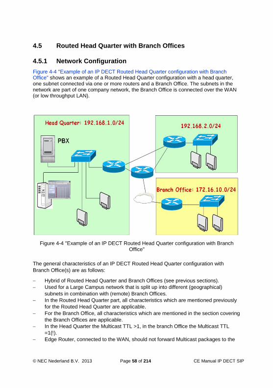
© NEC Nederland B.V. 2013 Page 58 of 214 CE Manual IP DECT SIP
4.5 Routed Head Quarter with Branch Offices
4.5.1 Network Configuration
Figure 4-4 "Example of an IP DECT Routed Head Quarter configuration with Branch Office" shows an example of a Routed Head Quarter configuration with a head quarter, one subnet connected via one or more routers and a Branch Office. The subnets in the network are part of one company network, the Branch Office is connected over the WAN (or low throughput LAN).
Figure 4-4 "Example of an IP DECT Routed Head Quarter configuration with Branch Office"
The general characteristics of an IP DECT Routed Head Quarter configuration with
Branch Office(s) are as follows:
Hybrid of Routed Head Quarter and Branch Offices (see previous sections).
Used for a Large Campus network that is split up into different (geographical)
subnets in combination with (remote) Branch Offices.
In the Routed Head Quarter part, all characteristics which are mentioned previously
for the Routed Head Quarter are applicable.
For the Branch Office, all characteristics which are mentioned in the section covering
the Branch Offices are applicable.
In the Head Quarter the Multicast TTL >1, in the branch Office the Multicast TTL
=1(!).
Edge Router, connected to the WAN, should not forward Multicast packages to the

CE Manual IP DECT Page 59 of 214 © NEC Nederland B.V. 2013
WAN.
Full support of seamless handover between all DAPs in the Head Quarters
configuration with the subnet.
Routers in the Head Quarter must support IP Multicast routing.
In the IP DECT configuration, you must define which subnets are in the Head
Quarters and which subnet(s) is/are Branch Office subnets. You must do that by
means of specifying the subnet mask that is needed to cover all Head Quarters
subnetworks (e.g. 255.255.252.0 for in this example.).
4.5.2 Settings in the DAP Configurator
The DAP Configurator is described in Chapter 9. CONFIGURATION - DAP
CONFIGURATOR TOOL. However, in this section you will find an example of a setup for
a Routed Head Quarter with Branch Office configuration.

© NEC Nederland B.V. 2013 Page 60 of 214 CE Manual IP DECT SIP
4.6 Routed Head Quarter with Branch Offices
4.6.1 Network Configuration
Figure 4-5 "Example of an IP DECT Routed Head Quarter configuration with a Routed Branch Office" shows an example of a Routed Head Quarter configuration with a head quarter, one subnet connected via one or more routers and a Branch Office. The subnets in the network are part of one company network, the Branch Office is connected over the WAN (or low throughput LAN).
Figure 4-5 "Example of an IP DECT Routed Head Quarter configuration with a Routed Branch Office"
The general characteristics of an IP DECT Routed Head Quarter configuration with
Routed Branch office are as follows:
Hybrid of Routed Head Quarter and Branch Offices (see previous sections).
Used for a Large Campus network that is split up into different (geographical)
subnets in combination with remote Routed Branch Offices.
In the Routed Head Quarter part, all characteristics which are mentioned previously
for the Routed Head Quarter are applicable.
In the Routed Branch Office part, all characteristics which are mentioned previously
for the Routed Head Quarter are applicable, except for that the Routed Branch Office
must be in different subnets than the Routed Head Quarter.

CE Manual IP DECT Page 61 of 214 © NEC Nederland B.V. 2013
In the Head Quarter the Multicast TTL >1, and in the branch Office the Multicast TTL
>1(!).
Edge Router, connected to the WAN, should not forward Multicast packages to the
WAN.
The Routers between the Routed Head Quarter and the Routed Branch Office
should block Multicast!
Full support of seamless handover between all DAPs in the Head Quarters
configuration with the subnet. Full support of hand over in the Routed Branch Office..
No handover between the Routed Head Quarter and the Routed Branch Office.
Routers in the Head Quarter must support IP Multicast routing.
Routers in the Routed Branch Office should support IP Multicast Routing.
In the IP DECT configuration, you must define which subnets are in the Head
Quarters and which subnet(s) is/are Branch Office subnets. You must do that by
means of specifying the Aggregated subnet mask that is needed to cover all Head
Quarters subnetworks (e.g. 255.255.252.0 for in this example.). Also in the Routed
Branch Office, you must calculate the Aggregated subnet mask that covers all
subnets in the Routed Branch Office.
4.6.2 Settings in the DAP Configurator
The DAP Configurator is described in Chapter 9. CONFIGURATION - DAP
CONFIGURATOR TOOL. However, in this section you will find an example of a setup for
a Routed Head Quarter with Routed Branch Office configuration.

© NEC Nederland B.V. 2013 Page 62 of 214 CE Manual IP DECT SIP
Note: The Netmask Length in both items in the screenshot above is the Aggregated
Subnet Mask, not the real subnet mask.

CE Manual IP DECT Page 63 of 214 © NEC Nederland B.V. 2013
5 PBX Configuration for IP DECT Devices
5.1 General
The PBX setup for IP DECT uses the same procedures used for setting up standard SIP or iSIP extensions on either the SV8100/SL1100/SL1000 systems. The procedure consists of 4 sub procedures:
-Setting up the IPL configuration (IP addresses etc.)
-Setting up the IPL gateway addresses.
-Setting up the IP DECT configuration
-Setting up the IP DECT features
In the following sections, examples are given on how to setup the PBX. If the
information is not sufficient, consult the relevant PBX documentation for further
information. Screenshots presented will differ in appearance dependant on the PBX the IP DECT is connecting to although the functionality is the same.
Note: Ensure that the extension numbers you want to setup for IP DECT extensions
have not been used for other IP devices in the PBX. Also make sure the IP
DECT extensions are either not yet setup in the IP DECT configuration or are
switched off. If not, there may be registration data in the PBX which causes the
handsets to perform improperly.
Note: For SV8100 R1 – R3 Main Software: Please make sure all standard SIP IP
DECT extensions are placed in an unused IP Duplication Group. SV8100 Main
Software 4 or newer will assign the standard SIP devices to a group
automatically. iSIP IP DECT devices are not required to be entered in an IP
Duplication Group.
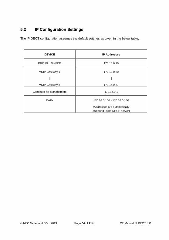
© NEC Nederland B.V. 2013 Page 64 of 214 CE Manual IP DECT SIP
DEVICE IP Addresses
PBX IPL / VoIPDB 170.16.0.10
VOIP Gateway 1
||
VOIP Gateway 8
170.16.0.20
||
170.16.0.27
Computer for Management 170.16.0.1
DAPs 170.16.0.100 - 170.16.0.150
(Addresses are automatically
assigned using DHCP server)
5.2 IP Configuration Settings
The IP DECT configuration assumes the default settings as given in the below table.

CE Manual IP DECT Page 65 of 214 © NEC Nederland B.V. 2013
5.2.1 Configure PBX VoIP IP Addressing
Actions
1. Ensure that the relevant PC Programming tool for offline programming of your
PBX is running on your maintenance computer. If not, start the application
and connect to the PBX (select “Communications” menu > “Connect”).
2. Take a full download of the PBX configuration.
3. Navigate to Wizards > Advanced Items > IP SIP > Blades > CCPU IP Address or if using the System Data commands then navigate to PRG area 10-12.
4. Set the IPL or VoIPDB IP address and Subnet Mask (PRG items 9 and 10)
information to the required settings for the customers network. 5. Click the Apply button when finished.

© NEC Nederland B.V. 2013 Page 66 of 214 CE Manual IP DECT SIP
5.2.2 Configure PBX VoIP Gateway(s) IP Addressing
Actions
1. Navigate to Wizards > Advanced Items > IP SIP > Blades > VoIP Resource IP Address or if using the System Data commands then navigate to PRG area 84-26.
2. If using an IPLA card in an SV8100 then enter the IP addresses starting from VoIP Gateway interface 1. Each gateway IP address handles 16 DSP channels so a 32 channel card will require 2 IP addresses configuring, a 64 channel card will require 4 IP addresses, and a 128 channel card will need 8 IP addressess configured. Make sure the IP addresses are correct for the customer’s network and are not duplicated on the network.
For an IPLB card installed in the SV8100 or VoIPDB in a SL1100/SL1000 you only need to enter a single IP address in the VoIP Gateway 1 details. Again make sure the IP addresses are correct for the customer’s network and are not duplicated on the network.
Normally the port numbers are left as the default values and start from 10020
for RTP and 10021 for RTCP increasing in steps of 32 port numbers (16 RTP
+ 16 RTCP ports) per VoIP Gateway IP address.
3. Click the Apply button when finished.

CE Manual IP DECT Page 67 of 214 © NEC Nederland B.V. 2013
5.3 Configure Common IP DECT Settings
Actions
1. Navigate to Wizards > Advanced Items > IP DECT > IP DECT Setup or if using
the System Data commands then navigate to PRG areas 10-33, 84-19, 10-20,
10-02.
2. Enter the required standard SIP IP DECT settings as per your installation requirements.
Authentication Mode 10-33-02 0=Disabled
1=Enabled
(default=1*)
*R7 and above
If enabled the SIP
extension must
register with the
'Authentication
Password' entered
in SIP Terminal
Setup. If
authentication not

© NEC Nederland B.V. 2013 Page 68 of 214 CE Manual IP DECT SIP
required then this
setting can be
disabled.
DTMF Relay Mode 84-19-32 0=Disabled
1=RFC2833
(default=0)
Enable RFC2833 if
you require sending
DTMF tones as an
event packet rather
than in-band of the
RTP speech path.
IP-DECT Directory
Access
10-20-01
Device
14
0=Not Used
If using the PBX
common speed
dials as an IP
DECT Central
Directory. Then
normally this port is
configured as
30160 as also set in
the IP DECT
Configurator.
Trunk Access Code 10-02-05 Blank=Not
Used
Enter the trunk
access code digits
required for placing
an outgoing call.
G.711 Maximum
Audio Frame Size
84-19-01 0=10ms
1=20ms
2=30ms
3=40ms
It is recommended
that this be set at
30ms if being used.

CE Manual IP DECT Page 69 of 214 © NEC Nederland B.V. 2013
(default=1)
G.729 Maximum
Audio Frame Size
84-19-07 0=10ms
1=20ms
2=30ms
3=40ms
4=50ms
5=60ms
(default=1)
It is recommended
that this be set at
30ms if being used.
G.723 Maximum
Audio Frame Size
84-19-12 0=30ms
1=60ms
(default=0)
It is recommended
that this be set at
30ms if being used.
G.722 Maximum
Audio Frame Size
84-19-33 0=10ms
1=20ms
2=30ms
3=40ms
(default=2)
It is recommended
that this be set at
30ms if being used.
G.726 Maximum
Audio Frame Size
84-19-38 0=10ms
1=20ms
2=30ms
3=40ms
(default=2)
It is recommended
that this be set at
30ms if being used.
iLBC Maximum
Audio Frame Size
84-19-43 0=20ms
1=30ms
2=40ms
(default=1)
It is recommended
that this be set at
30ms if being used.
SIP Out of Range 24-02-15 0-30(sec) If no response to an

© NEC Nederland B.V. 2013 Page 70 of 214 CE Manual IP DECT SIP
Timer
(default=4)
outgoing INVITE for
standard SIP
terminal is received
within this time.
The system treats
that device as out
of range and
returns busy.
3. Click the Apply button when finished.

CE Manual IP DECT Page 71 of 214 © NEC Nederland B.V. 2013
5.4 Configuration of Standard SIP IP DECT Devices
Actions
Navigate to Wizards > Advanced Items > IP DECT > IP DECT Options or if using the System Data commands then navigate to PRG areas 11-02, 15-01, 15-05.
Determine a port range that is unallocated and available for IP DECT devices. Assign the IP DECT extension numbers to the relevant ports. If Authentication Mode (PRG 10-33-02) for added security is to be used between the PBX and IP DECT then assign an ‘Authentication Password’ (PRG 15-05-16) to the relevant extension ports here also. Check that the IP Duplication Allowed Group (PRG15-05-18) is set to ‘not used’ for all IP DECT extension numbers. Click the Apply button when finished.
5.4.1 Standard SIP IP DECT Features
Actions

© NEC Nederland B.V. 2013 Page 72 of 214 CE Manual IP DECT SIP
Navigate to Wizards > Advanced Items > IP DECT > IP DECT Features > COS per Mode or if using the System Data commands then navigate to PRG areas 11-02, 15-01, 20-06.
1. Assign the IP DECT extension numbers to an unused class of service group between the values 1 – 15.
By default all system extensions are members of class of service group 1.
Click the Apply button when finished. Navigate to Wizards > Advanced Items > IP DECT > IP DECT Features > IP DECT COS Features or if using the System Data commands then navigate to PRG areas 20-13, 20-11.

CE Manual IP DECT Page 73 of 214 © NEC Nederland B.V. 2013
If the IP DECT installation requires using Call Waiting or Call Forward Both Ring features between the PBX and standard SIP IP DECT devices. Enable either of the features on this screen for the class of service group the standard SIP IP DECT extensions were assigned to previously at step 2.
Click the Apply button when finished.

© NEC Nederland B.V. 2013 Page 74 of 214 CE Manual IP DECT SIP
5.5 Configuration of iSIP IP DECT Devices
Actions
Navigate to Wizards > Advanced Items > IP DECT > iSIP > iSIP Extensions or if using the System Data commands then navigate to PRG areas 11-02, 15-01, 15-02, 15-05 10-26, 20-02.
Determine the port range that is available/free. Assign the IP DECT extension numbers to the relevant ports. Configure the iSIP IP DECT settings as per your system requirements.
1. Extension 2. 11
-02-01
3. 0-9
4. (up to 8 digits)
5. Set up
Extension
6. numbers for
iSIP IP
7. DECT
telephones.
8. Name 9. 15
-01-01
10. Up to 12
characters
11. Define the
extension
12. names for the

CE Manual IP DECT Page 75 of 214 © NEC Nederland B.V. 2013
iSIP IP
13. DECT
telephones
14. LND -
Outgoing
15. Mode
16. 15
-02-13
17. 0=Extension/Trun
k Mode
18. 1=Trunk Mode
19. (default=1)
20. For iSIP IP
DECT
21. extensions this
should be
22. set to
Extension/Trunk
23. mode for the
Redial list
24. to store
internal/external
25. numbers.
26. CID List –
Call
27. Register
Mode
28. 15-02-34 29. 0=Extension/Trun
k Mode
30. 1=Trunk Mode
31. (default=1)
32. For iSIP IP
DECT
33. extensions this
should be
34. set to
Extension/Trunk
35. mode for the
caller ID
36. scroll list to
store
37. internal/externa
l
38. numbers.
39. Additional
40. Informatio
n
41. 15-05-28 42. 0=Do not inform
43. 1=Inform
44. (default=0)
45. To send
additional
46. details to iSIP
IP DECT
47. devices for call
history

© NEC Nederland B.V. 2013 Page 76 of 214 CE Manual IP DECT SIP
48. logging this
command
49. should be
enabled.
50. Paging
Protocol
51. 15-05-38 52. 0=Multicast
53. 1=Unicast
54. 2=Auto
55. (default=0)
56. If paging is
required with
57. an iSIP IP
DECT device
58. then this setting
59. should be set
as Unicast.
60. Be aware that
Unicast
61. paging will use
1 DSP
62. resource per
paged
63. device so
ensure you
64. have enough
DSP
65. resources on
66. the IPL card.
67. CODEC
Type
68. 15-05-15 69. 1=Type 1
70. 2=Type 2
71. 3=Type 3
72. 4=Type 4
73. 5=Type 5
74. (default=1)
75. Assign a
CODEC type
76. to be used for
iSIP IP
77. DECT devices.
78. DT700 80. 10-26-04 81. 0=Disabled 84. When enabled

CE Manual IP DECT Page 77 of 214 © NEC Nederland B.V. 2013
Peer to
79. Peer Mode
82. 1=Enabled
83. (default=1)
calls
85. between iSIP
IP DECT
86. devices and
other iSIP
87. devices will
direct the
88. RTP stream
peer to peer
89. without using
DSP
90. resources on
the IPL
91. card. When
disabled IPL
92. resources will
be used so
93. recommend
leaving
94. enabled.
95. CAP/Loop
Key
96. Operation
Mode
97. 20
-02-23
98. 0=CAP Key
Operation
99. Mode
100.
1=Loop Key Operation Mode
101. (default=1)
102. iSIP IP DECT
devices
103. use CAP key
operation
104. for external
Hold
105. operation. This
should
106. be set to CAP
Key
107. Operation
Mode if this is
108. required.

© NEC Nederland B.V. 2013 Page 78 of 214 CE Manual IP DECT SIP
Click the Apply button when finished.
5.5.1 Configure iSIP IP DECT CODEC Selection
Actions
1. Navigate to Wizards > Advanced Items > IP DECT > iSIP > iSIP
CODEC Settings or if using the System Data commands then navigate to PRG 84-24.
2. For the CODEC type the iSIP IP DECT devices are assigned to. The CODEC settings can be configured as per the installation requirements. Currently only the G.711 CODEC is supported with iSIP IP DECT devices.
G.711 Maximum 84-24-01 1=10ms The amount of audio

CE Manual IP DECT Page 79 of 214 © NEC Nederland B.V. 2013
Audio Frame Size 2=20ms
3=30ms
4=40ms
(default=2)
sent in each RTP packet
when using G.711.
Default is 20ms.
G.711 Type 84-24-03 0=A-Law
1=u-Law
(default=0)
This decides the G.711
type used. In EMEA
typically and by default
A-law is used.
Audio Capability
Priority
84-24-28 0=G.711
2=G.729
3=G.722
(default=0)
The priority choice of
CODEC to be used when
using this device.
Default is G.711.
3. Click the Apply button when finished.
5.5.2 Configure iSIP IP DECT Programmable Keys
Actions
1. Navigate to Wizards > Advanced Items > IP DECT > iSIP > iSIP
Function Keys or if using the System Data commands then navigate to PRG areas 11-02, 15-07, 15-20.

© NEC Nederland B.V. 2013 Page 80 of 214 CE Manual IP DECT SIP
2. Assign and configure function keys to iSIP IP DECT terminals. Keys 1 – 4 can be programmed. It is recommended the following template should be used for programming of these keys;
Key 1 = CAP Key (for external Hold call operation)
Key 2 = ICM Key (for internal Hold call operation)
Key 3 = User defined
Key 4 = User defined
3. Click the Apply button when finished.
5.5.3 Configure iSIP IP DECT Device Features
Actions
1. Navigate to Wizards > Advanced Items > IP DECT > iSIP > iSIP Feature > COS
per Mode or if using the System Data commands then navigate to PRG areas

CE Manual IP DECT Page 81 of 214 © NEC Nederland B.V. 2013
11-02, 15-01, 20-06.
2. Assign the iSIP IP DECT extension numbers to an unused class of service group between the values 1 – 15.
By default all system extensions are members of class of service group 1.
3. Click the Apply button when finished. 4. Navigate to Wizards > Advanced Items > IP DECT > iSIP > iSIP Feature > iSIP
COS Feature or if using the System Data commands then navigate to PRG 20-08.
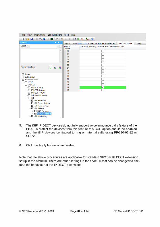
© NEC Nederland B.V. 2013 Page 82 of 214 CE Manual IP DECT SIP
5. The iSIP IP DECT devices do not fully support voice announce calls feature of the
PBX. To protect the devices from this feature this COS option should be enabled and the iSIP devices configured to ring on internal calls using PRG20-02-12 or SC:723.
6. Click the Apply button when finished.
Note that the above procedures are applicable for standard SIP/iSIP IP DECT extension
setup in the SV8100. There are other settings in the SV8100 that can be changed to fine-
tune the behaviour of the IP DECT extensions.
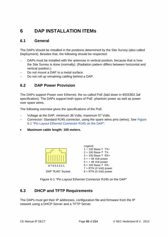
CE Manual IP DECT Page 83 of 214 © NEC Nederland B.V. 2013
6 DAP INSTALLATION ITEMs
6.1 General
The DAPs should be installed in the positions determined by the Site Survey (also called
Deployment). Besides that, the following should be respected:
DAPs must be installed with the antennas in vertical position, because that is how
the Site Survey is done (normally). (Radiation pattern differs between horizontal and
vertical position.)
Do not mount a DAP to a metal surface.
Do not roll up remaining cabling behind a DAP.
6.2 DAP Power Provision
The DAPs support Power over Ethernet, the so called PoE (laid down in IEEE802.3af
specification). The DAPs support both types of PoE: phantom power as well as power
over spare wires.
The following overview gives the specifications of the PoE.
Voltage at the DAP: minimum 36 Volts, maximum 57 Volts.
Connector: Standard RJ45 connector, using the spare wires pins (wires). See Figure
6-1 "Pin Layout Ethernet Connector RJ45 on the DAP".
Maximum cable length: 100 meters.
8 7 6 5 4 3 2 1
Legend:1 = 100 Base-T TX+2 = 100 Base-T TX-3 = 100 Base-T RX+4 = + 48 Volt power5 = + 48 Volt power6 = 100 Base-T RX-7 = RTN (0 Volt) power8 = RTN (0 Volt) powerDAP “RJ45” Socket
Figure 6-1 "Pin Layout Ethernet Connector RJ45 on the DAP"
6.3 DHCP and TFTP Requirements
The DAPs must get their IP addresses, configuration file and firmware from the IP
network using a DHCP Server and a TFTP Server.

© NEC Nederland B.V. 2013 Page 84 of 214 CE Manual IP DECT SIP
6.3.1 DHCP Server
When a DAP starts up, it tries to contact a DHCP server on the network. It should get the
following items from the DHCP server:
IP Address Subnet Mask Default Gateway IP address Next Boot Server IP address. This is the IP address of the TFTP Server (DHCP option 066).
Configuration file name (dapcfg.txt) available via the TFTP server (DHCP option
067). Note that you must enable option 67 in the DHCP server whether you fill in a file name or not. If you do not fill in a file name, the DAP will try to upload the default
configuration file name dapcfg.txt. If you fill in a file name in option 67, the DAP will
upload the configuration file name that you have entered here. It is strongly recommended to leave the file name field blank.
The easiest way to provide the DAPs with the correct data from the DHCP server, is using
the DHCP server that comes with the DAP Controller installation software. The DAP
Configurator tool allows you to setup the required DHCP server configuration easily.
Note: The DHCP Server that comes with the installation of the DAP Controller/Manager
is by default installed when you do the installation for “Multiple System”. If you do
the installation for “Single System”, the DHCP server is not installed by default.
However, if you select “Custom” installation you can choose to install or not install
the DHCP server.
However, if you don’t want to use the DHCP server that comes with the DAP Controller
installation, e.g. because there is DHCP server already in the network, you can use a
DHCP server of your choice. But make sure that the required parameters are delivered to
the DAPs.
6.3.2 TFTP Server
The configuration file and the firmware are uploaded to the DAP(s) using a TFTP server.
The DAP Controller software includes a TFTP Server. You can select that TFTP server
using the DAP Configurator. When you use the TFTP server that comes with the DAP
Controller, the TFTP Server configuration is automatically setup correctly.
Note: The TFTP Server that comes with the installation of the DAP Controller/Manager
is by default installed when you do the installation for “Multiple System”. If you do
the installation for “Single System”, the TFTP server is not installed by default.
However, if you select “Custom” installation you can choose to install or not install
the TFTP server. See installation procedure in Section 8.2 Installing the DAP
Controller Release .
CE Manual IP DECT Page 85 of 214 © NEC Nederland B.V. 2013
Note: Do not use the TFTP Server that comes with the DAP Controller for permanent
use. The TFTP Server is included in the DAP Controller software, in order to allow
you to setup a system easily, without DAP Controller permanently connected. In a
customer network with the DAP Manager permanently connected, please use the
TFTP server that the IT Manager recommends you to use.
6.3.3 Operation without DHCP or TFTP Server
If your DHCP server and or TFTP server is not permanently connected, you can store the
IP address and the configuration file in the DAPS in Flash memory. Note that the firmware
is always stored in Flash memory in a DAP.
To store the IP address configuration in Flash memory in the DAP, the following two
requirements must have been met:
The DHCP server must issue an “Infinite” lease time. (The DHCP server that comes
with the DAP Controller issues such a lease time by default!)
In the configuration setup, you must select “Replace” from the drop down menu for
IP Configuration in the boot options in the DAP Configurator screen. See section
10.3 “IP Settings”.
After this the DAP does not need a DHCP server anymore.
To store the Configuration file in Flash memory in the DAP, the following two
requirements must have been met:
The DHCP server must issue an “Infinite” lease time. (The DHCP server that comes
with the DAP Controller issues such a lease time by default!)
In the configuration setup, you must select “Replace” from the drop down menu for
DAP Configuration in the boot options in the DAP Configurator screen. See section
10.3 “IP Settings”.
When IP configuration and configuration file are stored in the DAP, the DAP does not
need to have a DHCP server nor TFTP server anymore in the startup processes.
Note: When a DAP starts up, it still does a DHCP request and TFTP request. If it gets
valid data from the DHCP Server and TFTP server, and a valid configuration file
with boot options set to “erase” or “Replace” it will either erase or replace the
stored data. If it doesn’t get those three items (DHCP, TFTP and valid file) the
DAP ignores the data that it has got, and starts up with the stored data.

© NEC Nederland B.V. 2013 Page 86 of 214 CE Manual IP DECT SIP
6.3.4 Using other DHCP and/or TFTP Servers
Note: If you install the DAP controller/Manager software as “Single System” the DHCP
and TFTP server are normally not installed. This means that you must use your
own DHCP or TFTP server. Consult the “Business Mobility IP DECT Advanced
Data Manual”, Chapter “Other DHCP/TFTP Servers” for examples of other
servers.
It is possible to use a DHCP server or TFTP server of your choice. However, the DHCP
server must provide the five parameters as mentioned in section 6.3.1 “DHCP Server”.
Also mind the lease time specification if you want to store IP configuration and/or DAP
configuration data in the DAP(s).
The TFTP server must be capable of handling as many simultaneous TFTP request as
there are DAPs. Remember, if the DAPs start up simultaneously, they do a TFTP request
simultaneously.
In the IP DECT Advanced Data Manual, you find examples of how to setup other DHCP
and TFTP servers.

CE Manual IP DECT Page 87 of 214 © NEC Nederland B.V. 2013
7 PREPARING YOUR DAP MANAGER PC
7.1 Hardware Requirements
The PC that is used for the Business Mobility IP DECT software must comply with the
following requirements:
CPU speed: 2,4 GHz or higher
1 Gb RAM or more
DVD-ROM drive
2Gb hard disk space free
7.2 Software Requirements
7.2.1 Operating System
The operating system for the DAP Controller/Manager PC should be as follows:
Windows 2003 SP2. Windows 2003 requires Rel. 2.
Windows XP Professional, SP2/SP3.
Windows 7 (not the Home version!)
Windows 2008 SP2
Windows 2008 R2
Note: The DAP Controller/Manager supports the International (English US) version of
the above mentioned MS Windows operating systems. Other MS Windows
language versions are not explicitly tested but are not expected to show any
problems. In case of problems please contact your IP DECT Supplier, and clearly
indicate which MS Windows version is used and the nature of the problem.
7.2.2 IIS and Internet Explorer
Besides the operating system, the Windows WEB server, called IIS (Internet Information
Services) is required. However, during installation, IIS is automatically installed.
When you install the DAP Controller software under Windows XP or Windows 2003, the
system may ask for the Operating System CD-ROM/DVD-ROM.
Note: On the client computer, you must use Internet Explorer 6.0 or higher to view the
DECT Manager WEB pages.
7.2.3 .NET Framework
The DAP Controller software requires .NET Framework 4.0. However, this is
automatically installed when installing the DAP Controller software.

© NEC Nederland B.V. 2013 Page 88 of 214 CE Manual IP DECT SIP
If there is already another version of .NET Framework on your PC, it does not do any
harm. .NET Framework versions can co-exist.
7.2.4 DHCP Server and TFTP Server
DHCP Server.
A DHCP Server is required in the network. However, the DAP Controller software
Release 5 includes a DHCP Server which is automatically configured when you run
the DAP Configurator tool. You may also use an existing DHCP Server in the
Network, or your own DHCP Server. For more info on other types of DHCP Servers,
consult chapter “Other DHCP/TFTP Servers” in the IP DECT Advanced Data
Manual.
However, make sure that the DHCP Server has correct settings for the Business
Mobility IP DECT and reference to the TFTP Server. Also make sure that you have
specified a default gateway/router address in the DHCP server, which is within the
subnet address range of the DAPs.
Note: You should use the built-in DHCP server that comes with the DAP Controller only
in very small installations (< 10 DAPs).
TFTP Server This can be an existing TFTP Server in the Network, or your own TFTP Server or the TFTP Server that is included in the IP DECT software. It is recommended to use the built-in TFTP server only in small installations (< 20 DAPs). For larger installations you should use a professional TFTP server.
7.3 Virtualization
The DAP Controller Release 6 supports virtualization on VMWare and Xen.
The Virtual Machine system should meet the requirements for a non-virtualized server. If
the network connection on the virtual machine is shared with another virtual machine or
the Host, make sure that there is sufficient bandwidth available for the DAP Controller
Virtual Machine.

CE Manual IP DECT Page 89 of 214 © NEC Nederland B.V. 2013
7.4 Marathon Fault Tolerancy
Marathon software with the EverRun® software and Citrix XenServer can be used to
provide fault tolerance on various software applications. IP DECT Release 6 supports
working on a Marathon platform, to provide fault tolerance.
For more information on the Marathon software, please consult the NEC Unified web
page.
Please note, that IP DECT supports built-in Redundancy on the DAP Controller and Proxy
without Marathon, See Chapter: 11 REDUNDANCY (General).

© NEC Nederland B.V. 2013 Page 90 of 214 CE Manual IP DECT SIP
8 INSTALLING THE DAP Controller/Manager
8.1 Preconditions
Make sure that you have decided which DHCP Server you are going to use. Also make
sure that you have decided which TFTP server you are going to use.
Also make sure that the network components (Switches, Routers) are correctly configured
for VoIP and IP multicast. Be fully aware of the network topology! Make sure that the
network supports IP Multicast between all network components that are used for Business
Mobility IP DECT.
8.2 Installing the DAP Controller Release 6
PROCEDURE: “Installation”
Actions
Make sure that you are logged in with Administrator Rights! Un-zip the DAP installer package. Double click setup.exe or setup.
Depending on the version of your Windows operating system, you will now see a security screen from Windows saying "Do you want to allow the following program to make changes to your computer?" Click Yes. You will see the following window.

CE Manual IP DECT Page 91 of 214 © NEC Nederland B.V. 2013
It indicates that the DAP Controller software supports your version of Windows. Click
Next to proceed.
Now the installation of "Prerequisites" takes place. Note that this can take several minutes! When all required prerequisites are installed, you will see the following window.
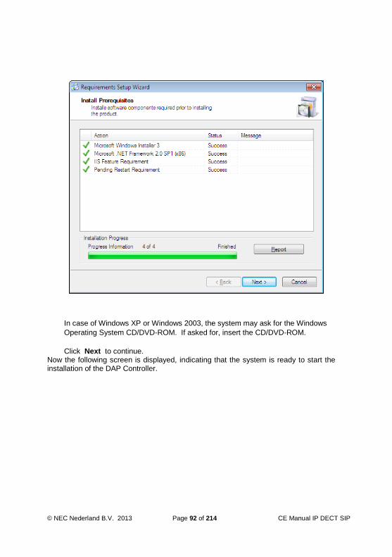
© NEC Nederland B.V. 2013 Page 92 of 214 CE Manual IP DECT SIP
In case of Windows XP or Windows 2003, the system may ask for the Windows
Operating System CD/DVD-ROM. If asked for, insert the CD/DVD-ROM.
Click Next to continue. Now the following screen is displayed, indicating that the system is ready to start the installation of the DAP Controller.

CE Manual IP DECT Page 93 of 214 © NEC Nederland B.V. 2013
Click Next to continue.
In the window that is displayed, please select the system type that you prefer, "Multiple System" or "Single System".

© NEC Nederland B.V. 2013 Page 94 of 214 CE Manual IP DECT SIP
Select Single System if you want to manage only one IP DECT system, or Multiple
System if you want to manage more than one IP DECT system with your PC. Click
Next.
Note: If you select “Single System” the DHCP Server and TFTP Server are not
installed (by default). However, if you want to install them anyway, select the
option “Custom” in step 9, and select DHCP Server and TFTP Server to
install.
Note: If you select Multiple System, the Services that are installed for IP DECT are
installed with startup parameters “Manual”. This means that they will not start
automatically when Windows boots up. If you select “Single System”, the
Services will be installed with startup parameters “Automatic”.
Note: You can always change the settings from Multiple System to Single System
and vice versa later on. See Section 9.4 Single Site / Multi Site“.
The following window is displayed.

CE Manual IP DECT Page 95 of 214 © NEC Nederland B.V. 2013
In this window “InstallShield Wizard” you should specify the “Setup Type”. Select
Standard and click Next. Note that if you want to fine tune the installation you
should select “Custom”.and click "Next". The system has collected sufficient info to start the actual installation.

© NEC Nederland B.V. 2013 Page 96 of 214 CE Manual IP DECT SIP
Click Install to start the installation.
When the installation is finished, you will see the window "InstallShield Wizard Completed".

CE Manual IP DECT Page 97 of 214 © NEC Nederland B.V. 2013
When the checkbox "Launch DAP Configurator is checked, the DAP Configurator will
start after clicking Finish. If not, the installation will finish, but the DAP Configurator
will not be started. However, you can start the DAP Configurator from the Programs
menu later.
Click Finish.

© NEC Nederland B.V. 2013 Page 98 of 214 CE Manual IP DECT SIP
9 CONFIGURATION - DAP CONFIGURATOR TOOL
9.1 General
The DAP Configurator is a tool for creating the configurations files for the DAP Manager
and DAPs. It is automatically installed when you install the DAP Controller/Manager. It is
also automatically started up during the installation of the DAP Controller/Manager.
After you went through the DAP Configurator windows and you have entered the correct
data, a number of configuration files are created.
You can always start-up the DAP Configurator tool using the shortcut to the DAP
Configurator tool in the “Start”, “All Programs”, “DAP Controller”, “DAP Application”, DAP
Configurator” menu.
9.2 Using the DAP Configurator
PROCEDURE: “Setting up the Configuration”
Actions Make sure that the installation of the DAP Manager was successfully executed. If you selected to start the DAP Configurator automatically after the installation, continue with step 3 in this procedure. If not, continue with the next step in this procedure. Start the DAP Configurator tool, via Start, All programs, DAP Controller, DAP Applications, DAP Configurator.

CE Manual IP DECT Page 99 of 214 © NEC Nederland B.V. 2013
If there is a problem with your network card (e.g. no cable connection), you will get a message. Please solve the problem. If you do not see this message, continue with the next step in this procedure. If you start-up the DAP Configurator for the first time, the system asks you for the license file.

© NEC Nederland B.V. 2013 Page 100 of 214 CE Manual IP DECT SIP
Select the license file and click open. If you do not have a license file, the system allows only up to 4 AP400S DAPs. You will see the following window displayed.

CE Manual IP DECT Page 101 of 214 © NEC Nederland B.V. 2013
Note that there are three sections in this window:
System Control section at the left side.
Settings Buttons at the top part of the window.
Data information part in the middle of the window.
If you start-up the DAP Configurator after configuring a system, you will see one or more extra buttons highlighted.
The way the buttons are greyed out, may be different in your system. In the System Control section (left side) click the button that is applicable to your need. For a new installation it will be New System.
Note: If you don’t want to start a new system installation, consult Section 9.3 “System Control Section” for more information on the buttons.
Note: If you want to change system settings, you must use the buttons in the top
part of the window. These buttons are described in Section 10.1 “Settings Buttons”.

© NEC Nederland B.V. 2013 Page 102 of 214 CE Manual IP DECT SIP
Continue with the section that is applicable for your situation.
9.3 System Control Section
9.3.1 General
The System Control section is located at the left side of the IP DECT Configurator
window.
Using one PC, you can manage more than one IP DECT system. For such an IP DECT
system you must setup a configuration on your PC. For each individual system, you can
change settings, using the buttons in the top part of the window. However, you can have
only one IP DECT system configuration active at the time. Therefore, you can start or stop
an IP DECT system.
Note: When you “Stop” an IP DECT system, the DAPs remain up-and-running. This
means that you can still make and receive phone calls. However, the DAP
Controller/Manager function is stopped, which means that some functionality (e.g.
messaging or moving between Branch Offices) does not work anymore.
The System Control part consists of the following buttons:
Home
Brings you back to the “start” screen.
New System
Allows you to create a new system configuration on your PC.
From the screen displayed when selecting a New System you can choose from the
following options;
License Type Description
Licensed System Used when R6 licensing mechanism is required to
use one of the licensed functional features of the
system.
Unlicensed system on
SV8100/SL1100
Used for normal deployment of IP DECT system
where no additional Release 6 functional features

CE Manual IP DECT Page 103 of 214 © NEC Nederland B.V. 2013
are required. Provides all the features available in a
Release 5 deployment.
Unlicensed system on
SV8100/SL1100 with
max. 4 AP400S
Used for small simple deployment of IP DECT
system when used with the AP400S access point.
Modify System
Allows you to Select a system configuration, and then manipulate or modify the
system.
Import System
Allows you to import a system configuration that has previously been exported. You
can import individual files from the exported .zip file or you can import the exported
.zip file in one go.
DAP Lite Download System (if displayed, it is greyed out)
Not applicable for this configuration.
Activate - Deactivate - System Status
The system status button leads you to a window in which you can control the system
status. See Section 9.3.2 “System Status Window”.
Export System
Allows you to export a system configuration. The exported file is always a .zip file
and contains all relevant system configuration files, including subscription data, DAP
configuration, DHCP data etc. The generated file can be imported later or can be
imported on another PC that you want to use as DAP Controller/Manager PC. Note
that this file can be used as a backup of your entire system configuration. Note that
you must select a System (configuration) first, using the “Modify System” button.
Delete System
This removes a System (configuration) from your PC. Note that you must select a
System (configuration) first, using the “Modify System” button.
Upgrade Installation
This allows you to upgrade the installation in a convenient way. You are guided
through the Upgrade procedure.
Save System
This saves the changes that you have made on a System (configuration) to files on
your PC. Note that after you saved the System (configuration), you can go to the
System Status button and then make the system active.
Default
Return to default settings.

© NEC Nederland B.V. 2013 Page 104 of 214 CE Manual IP DECT SIP
9.3.2 System Status Window
The window below is displayed when you click the “System Status” button. Note that
when you have more than one IP DECT system (configuration) you must selected a
System first, using the “Modify System” button and that you have saved your new
configuration before starting it.
Note: Make sure that you have stopped a previously running system.
Note: If you have made a new configuration, or if you have changes configuration
settings, make sure that you have saved the configuration first, using the “Save
System” button.
Note: Starting or stopping the system, only starts or stops the services and applications
running on the DAP Manager PC. This means that the DAPs remain operational.
Basic call handling is still possible if the DAPs are up and running.
The following services can be started or stopped:

CE Manual IP DECT Page 105 of 214 © NEC Nederland B.V. 2013
DDS
DDS (DECT Data Server) takes care of all DECT processes to and from the DAPs.
PCR
PCR (Performance Counter Retrieval) must be running to retrieve performance data
files and to enable sending an e-mail when performance thresholds are exceeded or
when a DAP goes down.
FWU
FirmWare Upload must be running if you want to use Firmware Upload.
TFTP
The TFTP Service refers to the TFTP server that was automatically installed with the
DAP Controller/Manager software.. Note that this is not the MS Windows TFTP
server. A TFTP Server must be running when one or more DAPs start-up. The TFTP
server supplies the DAPcfg.txt configuration file to the DAP(s). Note that there can
be only one TFTP server running on your PC. If you start the TFTP service make
sure that there is no other TFTP server running on your PC.
DAP Manager
Starts up the WEB service for IP DECT in IIS and opens the WEB Page of the DAP
Manager in Internet Explorer.
Note: If using Windows 2008, the status of the DAP Manager window (in Internet
Explorer) cannot be displayed. You will see an exclamation mark in the “run”
button to inform you.
The following programs can be started or stopped:
DHCP
The DHCP server runs as an application. It can be started or stopped. Make sure
that you are allowed to use a DHCP server on the Network.
DiagMonitor
The DiagMonitor is used to collect diagnostics data.
In addition to the services and applications on the PC, you can also reboot the DAPs.
When you start a System, the IP DECT Configurator may ask you if you want to reboot
the DAPs as well. Note that this can be necessary, because the configuration changes
must be uploaded to the DAPs as well. This requires a reboot!
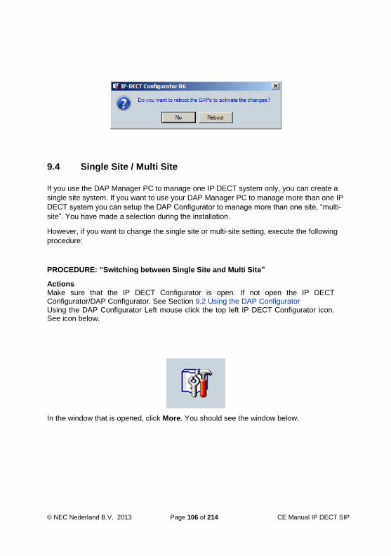
© NEC Nederland B.V. 2013 Page 106 of 214 CE Manual IP DECT SIP
9.4 Single Site / Multi Site
If you use the DAP Manager PC to manage one IP DECT system only, you can create a
single site system. If you want to use your DAP Manager PC to manage more than one IP
DECT system you can setup the DAP Configurator to manage more than one site, “multi-
site”. You have made a selection during the installation.
However, if you want to change the single site or multi-site setting, execute the following
procedure:
PROCEDURE: “Switching between Single Site and Multi Site”
Actions Make sure that the IP DECT Configurator is open. If not open the IP DECT Configurator/DAP Configurator. See Section 9.2 Using the DAP Configurator Using the DAP Configurator Left mouse click the top left IP DECT Configurator icon. See icon below.
In the window that is opened, click More. You should see the window below.

CE Manual IP DECT Page 107 of 214 © NEC Nederland B.V. 2013
You can switch to “Multiple system Support” or “Single System” by means of the check box in the window. Click Apply or OK to activate your selection.

© NEC Nederland B.V. 2013 Page 108 of 214 CE Manual IP DECT SIP
10 DAP CONFIGURATOR SETTINGS
10.1 Settings Buttons
In the top part of the IP DECT Configurator window, you see a number of buttons that
allows you to change settings in the system. In the following subsections these settings
are explained.
10.2 General Settings
When you click the “General Settings” the following window is displayed:
The following items must be entered:
System Name
Can be any given name. Note that this name will be used for a directory on the hard

CE Manual IP DECT Page 109 of 214 © NEC Nederland B.V. 2013
disk. This means that the name must comply with the requirements for Windows
directory names.
PBX Type
Select the platform to which the IP DECT system is (going to be) connected. Please
note that there is a list of SIP Servers. For SV8100/SL1100/SL1000 PBX systems
select the option “SIP on SV8100/SL1100”.
AP200/300 Package
Here you must enter the firmware file specification for the firmware package for the
AP200 and AP300. For SIP, the file name should look like this: 4910bxyz.dwl (e.g.
4910b610.dwl).
AP400 Package
Here you must enter the firmware file specification for the firmware package for the
AP400. For SIP, the file name should look like this: 4920bxyz.dwl (e.g.
4920b610.dwl).
AP400 Loader
Here you must enter the Loader file specification for the firmware package for the
AP400. For SIP, the file name should look like this: 49920112.dwl.
When finished, click “Apply”. On the bottom of the window, you should see, “License
valid”. Continue with clicking button “IP Settings”.
10.3 IP Settings
10.3.1 The Window
When you click the “IP Settings” button, the following window is displayed:

© NEC Nederland B.V. 2013 Page 110 of 214 CE Manual IP DECT SIP
10.3.2 IP Settings, tab “DAPs IP Configuration”
Please click the tab: DAPs IP configuration. Now the following fields can be edited:
DAPs Multicast IP address
Specify a Multicast IP address. If the network for your IP DECT system is used for
other purposes than IP DECT as well or if the network has a connection to the
company network or external network(s), you must ask the local IT manager for a
multicast address. If your IP DECT system is in a closed network, you can click the
button “Default IP” to use the default IP multicast address.
Port range from
By default the port range on the DAPs will start at port 3000. Please note that you
cannot change the port range.

CE Manual IP DECT Page 111 of 214 © NEC Nederland B.V. 2013
10.3.3 IP Settings, tab “DAP Controller IP Configuration”
Please click the tab: DAPs IP configuration.
Note: Depending on the Licenses that you have, one of the following screens is
displayed.
If you have a multiple DAP Controller system, please read Chapter 12 DAP Controller
Redundancy, before you continue making the configuration.
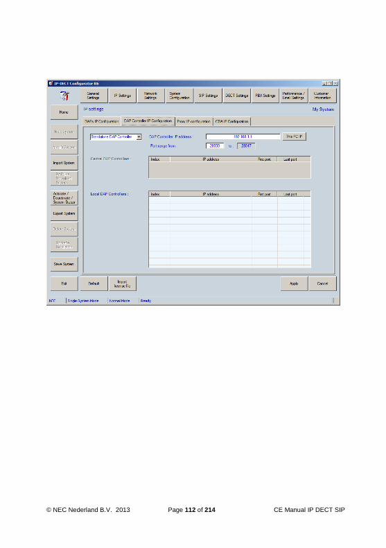
© NEC Nederland B.V. 2013 Page 112 of 214 CE Manual IP DECT SIP

CE Manual IP DECT Page 113 of 214 © NEC Nederland B.V. 2013
Note: You fill in the data of all DAP Controllers in the DAP Configurator of the Primary
DAP Controller.
DAP Controller IP Address
DAP Controller/Manager PC IP address. You can easily click the button “This PC IP”
to copy the IP address of your PC into this field.
Port range from
Start of port range in use for IP DECT on the DAP Controller/Manager PC. Note that
this port range is automatically filled in. Please do not change manually.
Enter the IP Addresses of the DAP Controllers that are in your system.

© NEC Nederland B.V. 2013 Page 114 of 214 CE Manual IP DECT SIP
Note: When you enter more DAP Controllers than your License allows, you will get the
message “License Violation”.
10.3.4 IP Settings, tab “Proxy IP Configuration”
Please click the tab: Proxy IP configuration. Now the following fields can be edited:
Single Gate Keeper
Click this radio button to select a system type with only one gatekeeper.
Proxy IP address
Enter the IP address of the SIP Proxy.
Proxy port number
Enter SIP port number on the SIP Proxy. The default port is 5070 when SIP on
SV8100/SL1100 is selected as the PBX type on the General settings page.

CE Manual IP DECT Page 115 of 214 © NEC Nederland B.V. 2013
Multiple gatekeepers.
When you click this radio button, you are able to enter more than one SIP Proxy
address. This can be useful for Netlink redundancy when having a secondary Netlink
node for failover or when networking multiple systems using Aspirenet, K-CCIS or
SIP. You can add as many proxies as you want.
Strip DNR prefix
When you check this checkbox, the system will strip one or more digits from the
subscribed number and send the remaining digits to the SIP proxy. In case of a
system with one SIP proxy the digit(s) are configured in the “SIP Settings” window,
under the tab: “Configuration settings”.
In case of a multi gatekeeper configuration, the digits are specified in the table of
Proxies in this window.
Multiple SIP Proxies settings.
When you select “Multiple Gatekeepers, the table in which you can add gatekeepers is
activated. Right mouse click inside the table and select “new” to add a gatekeeper. The
following items need to be entered.
Index
This is an automatically assigned unique identifier per Proxy. This can be used to
specify priorities in SIP Proxies (See Chapter. 13 SIP PROXY REDUNDANCY).
IP Address
Enter the IP address of the next SIP Proxy. Note that the first proxy is already in the
list.
Port
Enter the port number for the next SIP Proxy.
DNR Prefix (Optional)
You can enter an extension number prefix. If specified the extension numbers that
start with this number will register on the associated SIP Proxy.
Strip Prefix
If this check box is checked, the prefix of the subscribed number will be stripped. The
remaining digits are sent to the SIP Proxy.
Note that this checkbox is valid for all Proxies in one go. You cannot switch this
function on for one Proxy and switch off for another.
Also note that this same check box is also available in the SIP Settings window
under “configuration items”. Both are the same!
Domain
Specify the Domain IP address or the Domain name of the proxy. Note that in the
SIP Settings button, there is also the possibility to enter a default Domain name
which is used when you do not enter a Domain name here.
PBX
This is not required to be entered in a SIP on SV8100/SL1100 configuration.

© NEC Nederland B.V. 2013 Page 116 of 214 CE Manual IP DECT SIP
10.3.5 IP Settings, tab “CDA IP Configuration”
Please click the tab: CDA IP Configuration. Now the following fields can be edited:
Corporate directory IP Address
The IP address of the Central Directory Server (if applicable). The Abbreviated
Dialling tables of the connected PBX can be shared as a Central Directory Server by
entering the PBX IP address.
Corporate Directory port number
Port number on the Central Directory server. Default port number is 30160. This port
number must be configured in the PBX configuration also if the PBX Abbreviated
Dialling tables are being shared as a Central Directory Server.

CE Manual IP DECT Page 117 of 214 © NEC Nederland B.V. 2013
10.4 Network Settings
10.4.1 Network Settings, tab “Network Card Settings”
Please click the tab: Network card settings. Now the following fields can be edited:
Select network card connected to the IP DECT system.
If you have more than one network card in your system, select the network card that
you want to use here.
The network card data is displayed. Please note that you cannot change the network
card data here!
Change IP address, subnet mask and default gateway of this PC in the following values on system activation.
If this box is checked, the IP address, subnet mask and default gatekeeper of your
network card is automatically changed to the DAP Controller IP address that you

© NEC Nederland B.V. 2013 Page 118 of 214 CE Manual IP DECT SIP
have specified in Sub-section 10.3 “IP Settings”. This can be useful when you
manage more than one IP DECT system with your computer. The moment that you
start up one of your DECT system configurations, the IP settings of your network
card are automatically changed to the right settings for that particular system.
Please not that the IP settings on the network card are automatically changed, but
are not changed back to the previous settings.
This check box is greyed out in a Single System mode.
10.4.2 Network Settings, tab “DHCP Settings”
Please click the tab: DHCP Settings. Now the following fields can be edited:
Run DHCP Server on this PC
If you check this box, the DHCP Server that is installed on your PC for IP DECT will
be activated. Note that this DHCP Server accepts DHCP requests from DAPs only if

CE Manual IP DECT Page 119 of 214 © NEC Nederland B.V. 2013
you check the checkbox “DAP IP range exclusive for DAPs only”. In that case it will
ignore other DHCP requests. When you use the DHCP Server it will issue addresses
in the range that you specify in the “DAP IP Range”.
When enabled, it runs as an Application under MS Windows. The settings are stored
in the file dhcpsrv.ini in the system directory.
DAP IP Range
Specify IP address range that will be issued to the DAPs.
DAP IP Address range exclusive for DAPs only.
If checked, the DHCP server will respond to DAP requests only. This is based on the
“Vendor Class ID” that the DAPs issue when they do a DHCP request.
Subnet Mask.
Self explaining.
Default Gateway
Self explaining.
Ask for confirmation before starting the DHCP server
Self explaining.
Monitor DHCP Server
This allows you to monitor the DHCP activity of the built-in DHCP server. You see
the results in the System Status Window, which is opened when you click the button
“Activate / Deactivate / System Status”. See section 9.3.2 “System Status Window”.
Note: The built-in DHCP issues an “unlimited” lease time.

© NEC Nederland B.V. 2013 Page 120 of 214 CE Manual IP DECT SIP
10.4.3 Network Settings, tab “TFTP Settings”
Please click the tab: TFTP Settings. Now the following fields can be edited:
Run TFTP Server on this PC
If this box is checked, a TFTP Server will be running on your PC as “Service”. The
settings for the TFTP Server are automatically set correct for your configuration.
Note that a TFTP Server is needed when a DAP starts up, unless the configuration
file is stored in the DAP.
TFTP Server
Select the TFTP Server that you want to use for the IP DECT Configuration. If you
select the “3Com Tftp Server on this PC” it enables the TFTP server that is part of
the DAP Controller/Manager software package. When enabled, it runs as “Service”
under MS Windows. The settings are stored in the file 3CTftpSvc.ini
TFTP Folder
Automatically filled in. The TFTP folder is the folder where all system information is

CE Manual IP DECT Page 121 of 214 © NEC Nederland B.V. 2013
stored. Default folder is: C:\Documents and Settings\All
Users\Application data\Nec\DAP Controller\<system name>. When
you are using Windows 7 or Windows 2008, the directory is
C:\ProgramData\Nec\DAP Controller\<system name>
TFTP Server IP Address.
This is the IP address of the machine where the TFTP server is running. When you
have chosen to use the built-in TFTP server, you cannot change this IP address
because it is the IP address of your machine.
Monitor TFTP Server
This allows you to monitor the TFTP activity of the built-in TFTP server. You see the
results in the System Status Window, which is opened when you click the button
“Activate / Deactivate / System Status”. See section 9.3.2 “System Status Window”.

© NEC Nederland B.V. 2013 Page 122 of 214 CE Manual IP DECT SIP
10.4.4 Network Settings, tab “Leased IP Addresses”.
Please click the tab: Leased IP Addresses. Now you see a list of Leased IP addresses in
the Built-in DHCP Server.
In this window, you can delete/change/add the relationship between MAC addresses and
leased IP addresses. You have access to these settings by means of right mouse clicking
a line in the Leased IP Addresses window.

CE Manual IP DECT Page 123 of 214 © NEC Nederland B.V. 2013
10.4.5 Network Settings, tab “QoS Settings”
Please click the tab: QoS Settings. Now the following fields can be edited:
QoS on Layer 2
When you check this checkbox, the IEEE802.1p/q field in the layer 2 data package
will be used.
If enabled, you must specify the Priority level for Layer 2 (IEEE802.1p) and the
VLAN ID (IEEE802.1Q). The Priority value is a three bit value which must be entered
as decimal value 0 ... 7, where 7 is the highest priority.
User Priority
The Priority value is a three bit value which must be entered as decimal value 0 ... 7,
where 7 is the highest priority.
VLAN ID
Here you can specify a VLAN ID. Note that “0” means no VLAN specified.

© NEC Nederland B.V. 2013 Page 124 of 214 CE Manual IP DECT SIP
QoS on Layer 3
Here you can enable Quality of Service on Layer 3.
DSCP
If you have enabled QoS on layer 3, you must specify the DiffServ CodePoint
(DSCP) value in decimal, in the range 0 ... 63. Note that this is not the AF (Assured
Forwarding) class selector/service level or EF (Expedited Forwarding) class
selector/service level. This means that if you want to apply the “EF” class
selector/service level (53), you should enter the DSCP decimal value “46” (binary
101110).
10.4.6 Network Settings, tab “Boot options”
Please click the tab: Boot Options. Now the following fields can be edited:

CE Manual IP DECT Page 125 of 214 © NEC Nederland B.V. 2013
DAP Boot options.
This allows you to store the IP address data and Configuration data into Flash
memory in the DAP. When stored, a DAP does not need a DHCP/TFTP server
anymore. Note that you can “Store” or “Erase” data.
Note: Data is stored when you have selected to store data AND when the DHCP server
issues an “Infinite” lease time.
When finished, click “Apply” and continue with clicking button “System Configuration”.
10.5 System Configuration
When you click the “System Configuration” button, the following window is displayed:
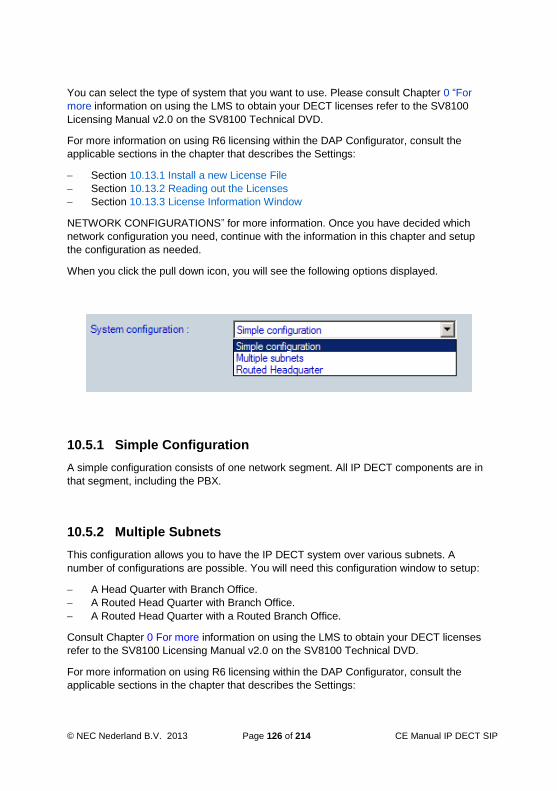
© NEC Nederland B.V. 2013 Page 126 of 214 CE Manual IP DECT SIP
You can select the type of system that you want to use. Please consult Chapter 0 “For
more information on using the LMS to obtain your DECT licenses refer to the SV8100
Licensing Manual v2.0 on the SV8100 Technical DVD.
For more information on using R6 licensing within the DAP Configurator, consult the
applicable sections in the chapter that describes the Settings:
Section 10.13.1 Install a new License File
Section 10.13.2 Reading out the Licenses
Section 10.13.3 License Information Window
NETWORK CONFIGURATIONS” for more information. Once you have decided which
network configuration you need, continue with the information in this chapter and setup
the configuration as needed.
When you click the pull down icon, you will see the following options displayed.
10.5.1 Simple Configuration
A simple configuration consists of one network segment. All IP DECT components are in
that segment, including the PBX.
10.5.2 Multiple Subnets
This configuration allows you to have the IP DECT system over various subnets. A
number of configurations are possible. You will need this configuration window to setup:
A Head Quarter with Branch Office.
A Routed Head Quarter with Branch Office.
A Routed Head Quarter with a Routed Branch Office.
Consult Chapter 0 For more information on using the LMS to obtain your DECT licenses
refer to the SV8100 Licensing Manual v2.0 on the SV8100 Technical DVD.
For more information on using R6 licensing within the DAP Configurator, consult the
applicable sections in the chapter that describes the Settings:

CE Manual IP DECT Page 127 of 214 © NEC Nederland B.V. 2013
Section 10.13.1 Install a new License File
Section 10.13.2 Reading out the Licenses
Section 10.13.3 License Information Window
NETWORK CONFIGURATIONS for more information.
The window “Multiple Subnets” offers the possibility to specify a certain RPN range per
Branch Office Subnet. Note that you should set the RPN range wide enough to allow
future system expansion.
You will see the following screen:

© NEC Nederland B.V. 2013 Page 128 of 214 CE Manual IP DECT SIP
In this window you can right mouse click a line in the shown table. Then you can add, edit
or delete a Branch Office configuration. The following items must be specified:
Subnet
In almost all configurations, this is the subnet address. It is the first address in the
subnet range, e.g. 192.168.1.0/24.
However, note that this subnet can also be an Aggregated Subnet. An “Aggregated
Subnet” is a Virtual network definition which determines the network boundaries for
an IP DECT Network in which seamless handover is possible AND which is running
over more than one IP subnet. An Aggregated subnet is a kind of “virtual” subnet
that combines several real subnets.
This is used when your IP DECT system is operational on one location on more than
one subnet, with seamless handover.
All DAPs within the Aggregated Subnet allow seamless handover between each
other, although they are spread over different real subnets with Routers in between.
.
So, if you have IP DECT running on more than one IP subnet, where seamless
handover is required, you must calculate the Aggregated subnet and fill it in, in this
window
Example of an Aggregated Subnet:
There are two subnets in which IP DECT is installed. The Router supports IP
Multicast and there is seamless handover between the DAPs in different IP subnets.
One subnet is 192.168.1.0/24 and the other is 192.168.4.0/24. The aggregated
subnet is 192.168.0.0/21. This covers both subnets.
All subnet addresses outside the Aggregated subnet, will be regarded as Branch
Offices.
Note: The Aggregated Subnet, together with the Aggregated Subnet Mask are only
applicable for IP DECT. So, never use Aggregated Subnet mask on your Network
card or other network devices.
Mask Length
This is the subnet mask length, the number of bits used to identify the network part.
In general, this will be a real netmask length, applicable for one network segment.
Example:
When your subnet mask is 255.255.255.0, it means 24 bits for the network part and
8 bits to identify the host part. So, in this example you must fill in 24.
Note: The Mask Length can be the Aggregated subnet mask length. See the bullet
above (Subnet) where the Aggregated subnet is explained.

CE Manual IP DECT Page 129 of 214 © NEC Nederland B.V. 2013
RPN range
Lowest RPN and highest RPN in this Branch Office.
Note: Make sure that you enter all subnet. DAP in subnets, not included in this list will
fail to complete the boot process.
Time to Live value
The Time to Live value is used for the Multicast traffic. If the Time to Live for the
Multicast is set to “1”, Router(s) will not forward multicast traffic for the associated
Multicast Group. If the Time to Live is higher than “1”, Router(s) will forward multicast
traffic for the associated Multicast Group (depending on settings in a Router).
If you are using an Aggregated subnet (see bullet “Subnet” above), multicast routing
is required between the different Subnets and therefore the TTL must be set to a
value higher than 1 (advised 32).
If the subnet that you have filled in, is a real subnet, not Aggregated, you must make
sure that the Time to Live is always 1.
Gate Keeper
This is the Proxy address for the DAPs in this Subnet.
Subnet name
Can be any given name. It is used to identify the Branch Office.
Time Offset
Self explaining.
Country
This is important to make sure that the frequencies and tones are according to the
country requirements

© NEC Nederland B.V. 2013 Page 130 of 214 CE Manual IP DECT SIP
10.5.3 Routed Head Quarter
In this configuration, there are more than one network segments in the Head Quarter. The
routers in this configuration must forward IP Multicast packages.
The following settings can be entered/changed:
Time to Live value
The Time to Live value is used for the Multicast traffic. If the Time to Live for the
Multicast is set to “1”, multicast traffic will not be forwarded by a Router. If the Time
to Live is higher than “1”, multicast packages might be forwarded by the Router,
depending on settings in the Router.
Because you have selected the Router Head Quarter configuration, the Time to Live
will always be higher than one. Advised value is 32.
Aggregated Subnet mask
The “Agg. subnet mask” is the subnet mask for the DAPs to determine the network
boundaries for an IP DECT Network in which seamless handover is possible. It
should cover the network segments that are connected together using routers that
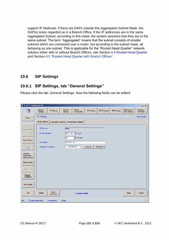
CE Manual IP DECT Page 131 of 214 © NEC Nederland B.V. 2013
support IP Multicast. If there are DAPs outside this Aggregated Subnet Mask, the
DAP(s) is/are regarded as in a Branch Office. If the IP addresses are in the same
Aggregated Subnet, according to this mask, the system assumes that they are in the
same subnet. The term “Aggregated” means that the subnet consists of smaller
subnets which are connected over a router, but according to the subnet mask, all
behaving as one subnet. This is applicable for the “Routed Head Quarter” network
solution either with or without Branch Offices, see Section 4.4 Routed Head Quarter
and Section 4.5 “Routed Head Quarter with Branch Offices”.
10.6 SIP Settings
10.6.1 SIP Settings, tab “General Settings”
Please click the tab: General Settings. Now the following fields can be edited:

© NEC Nederland B.V. 2013 Page 132 of 214 CE Manual IP DECT SIP
SIP Server
This is derived from the setting in Section 10.2General Settings. You cannot change
the SIP server type here.
Local time zone
Specify your time zone. Normally this setting is OK. You only need to change this
setting if you want to deviate from the Windows time zone settings.
SIP Domain
Here you must specify the Proxy IP Address (IP4, dotted format) or host name. Note
that if you do not specify an address here, the value of “Proxy IP address or host
name” is used.
Note that when you have entered a Domain name in the “IP Setting” window (see
section 10.3 ”IP Settings”, the Domain names specified there will have priority over
the Domain name that you specify here. The Domain name that you specify here is
regarded as default Domain name.
Registrar IP Address
IP address of the Registrar server.

CE Manual IP DECT Page 133 of 214 © NEC Nederland B.V. 2013
10.6.2 SIP Settings, tab “Configuration Settings”
Please click the tab: Configuration Settings. Now the following fields can be edited:
The following items can be entered or changed.
Note: The displayed Configuration items depend on the SIP Server selection. In
the screen capture and overviews below all possible configuration items are
mentioned. For your type of SIP Server, the number of Configuration items
may be less because the items that are not relevant for certain SIP server
are not displayed.
sdp-late-sendrecv
Enables the ability of the IP DECT system to issue an initial Invite without SDP
(Session Description Protocol) offer.
sdp_rfc3264
Enables “Hold” according to RFC3264.

© NEC Nederland B.V. 2013 Page 134 of 214 CE Manual IP DECT SIP
sdp_MoH
When enabled, no local tone is generated when the IP DECT handset is on “hold”
(recvonly mode).
sdp_payload_size
Offered payload size in the SDP (Session Description protocol) offer (in ms).
However, generally the proposed payload size of the opposite party is used.
sdp_DTMF-rfc2833
When enabled, DTMF digits are sent according to rfc2833 (in RTP). Otherwise the
DTMF digits are sent as SIP “INFO” messages.
mwi support
Message waiting indication supported, yes or no.
b2b_ua
Back-to-Back User Agent. Necessary for an un-attended transfer in an iS3000 SIP
server configuration. Must be set to “yes” for iS3000. Must be set to no in all other
cases.
max_int_dnr_length
Extension numbers longer than specified here are considered as external numbers.
Note that this only applies to numeric extension numbers.
sip_messaging
This option allows you to enable SIP Instant Messaging according to RFC3428.
Note: When you enable SIP Instant Messaging, the LRMS messages send from a
handset will always be send as SIP Instant Message and therefore not sent via
the DAP Controller anymore. This means that when SIP Messaging is enabled,
you cannot sent messages to the e.g. the Messenger@Net anymore!
transport protocol
Use the default protocol UDP. Only for iS3000 other protocols are supported.
Maximum Registration Interval=1
This is the SIP registration interval in minutes. This is not the registration interval per
handset.
When there is only one subscription in the DAP, the registration interval for that
subscription will be the time specified here. When there are two subscriptions in the
DAP, the registration interval for each of the subscriptions will be 2/<time specified>.
So it will be 2/1 minute. This means that each subscription will register each two
minutes.
Hash_is_nbr_complete_ind
The hash button can be used to indicate number complete or can be used as part of
the dialed number.
DNR_Prefix_to_add=

CE Manual IP DECT Page 135 of 214 © NEC Nederland B.V. 2013
If you want to add digits to the subscribed number, you can specify them here.
Strip_DNR_Prefix
This feature is exactly the same as the “Strip Prefix” check box in the window “IP
Settings”, see section 10.3 “IP Settings”.
Use_PP_name
If active, the portable name is send as calling line name to the opposite party. Note
that this feature is only supported on SIP extensions that supports this functionality.
Use this on your own risk.
diversion_status
In this parameter, you must enter the prefix that is used to activate follow-me. The
prefix should have been defined in the PBX as well and will be *21 in many
countries. When you have entered the prefix, IP DECT knows when a follow-me is
set on an extension and will therefore generate the diversion dial tone when going
off-hook. Note that this feature only works for the iS3000
dtmf_pt
This parameter allows you to specify the dtmf payload type for RFC2833
inplementation. Default is 96. The range is 96 ...127.
Return_to_primary
This parameter is used for a configuration with Proxy redundancy for SIP. See
Chapter 13 “SIP PROXY REDUNDANCY”.
multiple_call_appearance When the handset is busy and a second call comes in, you will hear a ticker tone and the display shows “waiting <cli>”. By means of the * button, you can toggle between the two calls. It behaves in a similar way as having a call on hold. Please note that the SIP Proxy must be able to support multiple call to one extension number as well.
Hash_is_release_enquiry_call
When you are in an equiry call and you end up on a device like a voice mail server,
you cannot hangup the phone without losing your call. I that case you can press the
# key to end you enquiry call but keep your original call.
Unattended_transfer_method.
There are three options: Proxy, Cancel, Replace. The following options should be
chosen for the related PBX types.
Proxy: use for iS3000 type of PBXs
Cancel: most commonly used for a wide range of PBX types.
Replace: used for Alcatel PBX types.
Call_waiting_indication.
Here you can specify the call waiting indication text which is displayed when there is
a call waiting.

© NEC Nederland B.V. 2013 Page 136 of 214 CE Manual IP DECT SIP
486=
Here you can enter the text that is displayed when the SIP Proxy sends error code
486
404=
Here you can specify the text that is displayed when the Proxy sends error code 404.
480=
Here you can specify the text that is displayed when the Proxy sends error code 480.
Note: This window does not show a field for the SIP Proxy address. The SIP Proxy IP
address must be specified in the “IP Configuration” window.See section10.3.4 IP
Settings, tab “Proxy IP Configuration”.
A typical SIP configuration for an SV8100/SL1100 PBX would include the following
settings and values to be configured. More details on the individual items are described
in detail above;
sdp_payload_size.
Set to Enabled and the value as 30ms.
sdp_DTMF-rfc2833.
Set to Enabled and the value as ‘Yes’ to use RFC2833 RTP Events for DTMF tones.
mwi support.
Set to Enabled for Message Waiting idication support.
return_to_primary.
In a Netlink deployment when a failover occurs to a secondary node. The handsets
will register to the next available SIP Proxy in the list of entered gatekeepers. If the
primary gatekeeper should become available again the handsets can either be
turned off and back on again to force them to register with the primary gatekeeper, or
alternatively the Return_to_primary setting should be enabled and a valid time
interval entered. 0 means the timer is disabled so enter a value of 1 or more. Once
this timer expires the handset subscriptions that are not active in a call and
registered with the primary proxy will try to re-register with the primary Proxy again.
multiple_call_appearance. Set to Enabled for call waiting support. Works in conjunction with the Call_waiting_indication setting.
unattended_transfer_method.
Set to Proxy_action.
call_waiting_indication.
Set to Enabled. Works in conjunction with the multiple_call_appearance setting.
isip_reg_port.
Set to Enabled and the value as 5080.
isip_sub_port.

CE Manual IP DECT Page 137 of 214 © NEC Nederland B.V. 2013
Set to Enabled and the value as 5081.
isip_preview_dial.
Set to Enabled for iSIP preview dial support.
isip_tac.
Set to Enabled and the value entered should be the same as the trunk access code
entered in the PBX. This is used for returning calls selected from the call history lists
on iSIP devices to ensure you can dial out by adding the trunk access code as a
prefix to the stored number.
isip_moh_tone.
Set to enabled and the value as 5. This is used by iSIP IP DECT devices for giving
MOH tone.

© NEC Nederland B.V. 2013 Page 138 of 214 CE Manual IP DECT SIP
10.6.3 SIP Settings, tab “Authentication Settings”
Please click the tab: Authentication Settings. Now the following fields can be edited:
Authentication Realm 1 . . . AuthenticationRealm 5
Up to 5 authentication realms can be specified. Note that if the Proxy requests for
authentication, it issues the Realm name. On receiving the Realm name, the IP
DECT system compares the received Realm name with the ones in this list. If the
Realm name matches, the “username” and the “Password” are sent to the Registrar
for authentication check.
A Realm name must be unique, do not enter a same Realm name in more than one
field.
Note: You can do authentication based on the User Name in the handset and on
entering a password into the handset. To achieve this functionality, do not enter a
Realm name that matches the Realm name of the Proxy. If IP DECT cannot find a
Realm name match, it will copy the Realm name that comes from the Proxy back

CE Manual IP DECT Page 139 of 214 © NEC Nederland B.V. 2013
to the Proxy again and will request for handset name authentication. This
mechanism works for the G355, G955 and I755 handset only with the latest
software in the handset.
User
The “user” is the name for login on the Proxy/Registrar server.
Note that you can fill in an actual username OR a %s . When you enter %s , the IP
DECT system sends the extension number of the handset making a call. This makes
the username extension number specific and should be configured if using either SIP
or SIP MLT Hotdesking on the PBX with the Portable Handset Sharing feature of IP
DECT.
Password
Password for authentication in the Proxy/Registrar. For standard SIP IP DECT
devices this will match the password in PRG15-05-16, which should be the same for
each extension to be registered in the PBX. With iSIP IP DECT devices using SIP
MLT Hotdesking on the PBX this will be the password entered in PRG84-22-02,
which again should be the same for each extension to be registered. However when
you enter %s as password or part of the password, IP DECT converts that to the
extension number and on the PBX you must ensure the password for each extension
to be registered is the correct extension number also.
When finished, click “Apply” and continue with clicking button “DECT Settings”.

© NEC Nederland B.V. 2013 Page 140 of 214 CE Manual IP DECT SIP
10.7 DECT Settings
10.7.1 DECT Settings, tab “DECT Settings”
Please click the tab: DECT Settings. Now the following fields can be edited:
Country Code
The Country code specifies the tone plan for IP DECT and also selects the correct
frequency range and transmitter output power.
PARI
Primary Access Rights Identifier. This is the Unique DECT System Identifier. It is an
8 digit hexadecimal string. It is a worldwide Unique Identifier which you should have
received together with your DECT system.
SARI
The SARI is the Secondary Access Rights Identifier, which is only needed if you use
Multi-Site subscriptions. If you do not use multi-site Subscriptions, leave this field to

CE Manual IP DECT Page 141 of 214 © NEC Nederland B.V. 2013
the default “FFFFFFFF”.
Frequency Table
This shows which DECT frequency range is used. This differs per part of the world.
Note that you cannot change the setting here, it is a result of the country that you
have selected.
Used carriers
By means of this field you can enable/disable the DECT carriers. Leave all carriers
enabled to make sure maximum bandwidth is available.
10.7.2 DECT Settings, tab “Handset Settings”
Please click the tab: Handset Settings. Now the following fields can be edited:

© NEC Nederland B.V. 2013 Page 142 of 214 CE Manual IP DECT SIP
Handset Page Timer
The Page Timer specifies the time in seconds between two page requests (retries).
Page timer retry value
The Page Retry Value specifies the maximum number of paging retries that are
issued, if paging a handset fails.
Send date and time to handset
If enabled the DAP Manager PC will be used to synchronise the time and date
information on the handsets.
Display handset name in DAP Manager INT
When enabled, the handset name (if present in the handset) will be displayed in the
DAP Manager, in the Subscriptions window, in the Comment field. The handset
name will be displayed between brackets.
Handset Polling time interval
This is a mechanism to check if the handset is still reachable. Here you specify the
polling interval time. If the handset is does not respond, it will be switched absent in
the IP DECT system.

CE Manual IP DECT Page 143 of 214 © NEC Nederland B.V. 2013
10.7.3 DECT Settings, tab “DAP Settings”
Please click the tab: DAP Settings. Now the following fields can be edited:
Broadcast Messaging
This enables broadcast messaging.
Local Message relay override
When “Local Message Override” is not checked, and the TCP/IP DECT Messaging
port (default 28001) is in state “Connected” (from e.g. a Messaging device) it is not
possible to do handset-to-handset messaging anymore without intervention of an
external messaging system. However, if you check the “Local Message override”
check box, handset-to-handset messaging remains possible even if the TCP/IP port
is in the state “connected”. This setting can be required for the messaging
functionality of “Business Connect” however, it should not be checked in case of the
Messenger@Net.
© NEC Nederland B.V. 2013 Page 144 of 214 CE Manual IP DECT SIP
SMS Presence
Send the absent/present status to dedicated applications via DMLS.
Move subscriptions non operational DAP after
When a DAP is down and the DAP Controller is up- and-running the subscription
records from that DAP will be moved to other DAPs. The time interval can be
specified here.
Absent DAP Threshold
When the number of absent DAPs is more than 2, the subscription data will NOT be
moved to other DAPs.
Please note that this is a fixed system parameter, and cannot be changed.
G729 mode:
The following items can be selected:
G.729 not supported = never use G.729
Use G729 when required = Setting as in previous versions of IP DECT. G.729 used in case of connection to Branch Office DAPs.
Preferred use of G.729 = IP DECT will always issue G.729 as preferred codec over G.711.
Only use G.729 = Do not use this setting!
Note: G.729 voice compression (G7A unit installed in AP300/AP400) could be the
answer for applying DECT in networks with limited bandwidth. The downside
however is that the voice quality will be less compared to uncompressed voice.
But under more demanding circumstances like environments with background
noise, the voice quality may become unacceptable if used in combination with
G.729. Therefore we advise not to apply G.729 on sites with a background noise.
When finished, click “Apply” and continue with clicking button “PBX Settings”.
10.7.4 DECT Settings, tab “Synchronization Settings”
When you see a tab called “Synchronization Settings”, it indicates that you have a license
for IP DECT in an environment with a lot of metal causing reflections. The license is offers
additional functionality to reduce the effects of the reflections. However, it is only available
on “Project Base” which means that it has to be installed by special maintenance
engineers. Therefore the Synchronization Settings window is not explained here. :

CE Manual IP DECT Page 145 of 214 © NEC Nederland B.V. 2013
10.8 PBX Settings
10.8.1 PBX Settings, tab “Handset Sharing”.
When you click the “Handset Sharing” tab , the following window is displayed:
Handset sharing
Checking this box, enables Portable Sharing, see Chapter 16 “PORTABLE
SHARING”.
Subscription prefix
First digit(s) of the subscribed number. If the first digit(s) of a subscription matches
with the digit(s) defined here, the handset is enabled for portable sharing.
Closing digit
Digit that must be entered on the handset after entering the extension number at
login. Default is “#”. Normally there is no need to change this digit.

© NEC Nederland B.V. 2013 Page 146 of 214 CE Manual IP DECT SIP
10.8.2 PBX Settings, tab “Three party conference Settings”
When you click the “Three party conference Settings” tab, the following window is
displayed:
The following items can be set/changed:
Initiation digit
Digit that must be dialled to start the three party conference.
Conference ID
The unique ID for the conference.
Conference IP Address
The IP address of the Conference server. (Used for RTP Speech path.)

CE Manual IP DECT Page 147 of 214 © NEC Nederland B.V. 2013
When finished, click “Apply” and continue with clicking button “Performance / Email
Settings”.
10.9 “Performance / E-mail Settings”
10.9.1 Performance / E-mail Settings, tab “PCR Settings”
When you click the “PCR Settings” tab, the following window is displayed:
The following parameters are available:
Interval UPM generation every:
With this interval, User Performance Measurement files are generated. Default value
is 1440 minutes (one day)
Interval EPM generation every:
With this interval, Equipment Performance Measurement files are generated. Default
value is 15 minutes.
Keep Performance data for . . . days

© NEC Nederland B.V. 2013 Page 148 of 214 CE Manual IP DECT SIP
Number of days that the performance data should be kept on the Hard Disk.
Start measurement at:
Each day performance measurement should take place, the performance
measurement will start at the time specified here.
Stop measurement at:
Each day performance measurement should take place, the performance
measurement will stop at the time specified here.
Create Performance counters every:
Specify the days that performance counter retrieval should take place.

CE Manual IP DECT Page 149 of 214 © NEC Nederland B.V. 2013
10.9.2 Performance / E-mail Settings, tab “Alarm Settings”
When you click the “Alarm Settings” tab, the following window is displayed:
Emails can be send automatically when a DAP goes down or when the channel
occupation threshold is exceeded for more than a number of seconds. Note that this will
only work when the DAP Controller/Manager is up-and-running. The PCR service must be
running on the DAP Controller/Manager PC.
Alarm Notification
Alarm notification can be send as an e-mail and/or to the Windows Event Log.
Please not that it is possible to convert the events, written to the event log, into
SNMP Traps (consult the Advanced Data Manual.).
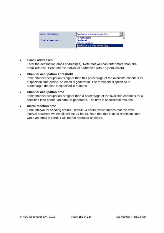
© NEC Nederland B.V. 2013 Page 150 of 214 CE Manual IP DECT SIP
E-mail addresses
Enter the destination email address(es). Note that you can enter more than one
email address. Separate the individual addresses with a ; (semi colon).
Channel occupation Threshold
If the channel occupation is higher than this percentage of the available channels for
a specified time period, an email is generated. The threshold is specified in
percentage, the time is specified in minutes.
Channel occupation time
If the channel occupation is higher than a percentage of the available channels for a
specified time period, an email is generated. The time is specified in minutes.
Alarm reaction time
Time interval for sending emails. Default 24 hours, which means that the time
interval between two emails will be 24 hours. Note that this is not a repetition timer.
Once an email is send, it will not be repeated anymore.

CE Manual IP DECT Page 151 of 214 © NEC Nederland B.V. 2013
10.9.3 Performance / E-mail Settings, tab “Archive Settings”
When you click the “Archive Settings” tab, the following window is displayed:
The following parameters can be adjusted:
Max. attachment size
This is the maximum attachment size. If the archive is larger than the size specified
here, it will be chopped into pieces of the specified size.
E-mail nightly created archive
This enables automatic sending an email with the nightly created archive file as
attachment.
E-mail address(es)
Enter the destination email address(es) as destination for the nightly created archive.
Note that you can enter more than one email address separated by ; (semi colon).

© NEC Nederland B.V. 2013 Page 152 of 214 CE Manual IP DECT SIP
Send archive every
Specify the days that the Archive should be send.
Stop sending archive after
After this date, archives are not automatically sent anymore.
10.9.4 Performance / E-mail Settings, tab “E-mail Settings”
When you click the “E-mail Settings” tab, the following window is displayed:
The following items are available:
SMTP Server
Enter the DNS name or the IP address of the SMTP mail server.
E-mail from
Enter the originators email address. Note that normally the SMTP server does not

CE Manual IP DECT Page 153 of 214 © NEC Nederland B.V. 2013
check the originators email address, which means that you can enter any email
address here.
Send test e-mail to
Select the addresses to which an e-mail should be send. Please note that these
addresses come from the Alarm Settings and Archive settings.
Test e-mail Click this button to send an email to the addresses that have checked checkboxes.
10.9.5 Performance / E-mail Settings, tab “Miscellaneous Settings”
When you click the “Miscellaneous” tab, the following window is displayed:

© NEC Nederland B.V. 2013 Page 154 of 214 CE Manual IP DECT SIP
CDS port
Here you can change the port number of the CDS. The CDS takes care of showing
the WEB pages. When you change the port here, the port of the WEB server for
CDS is changed. This means that you must enter the new port number in the URL
that you use to reach the WEB page. .
HTTP execution time out
This is a guarding timer for the ASP scripts. E.g. if the ASP web pages try to send an
archive and it takes longer than the time specified here, it will be terminated.
The time is specified in seconds.
Use client resolution
If you check this box, you cannot scroll anymore through lists but the available
information is chopped up into pages. You can select pages using tabs. If this box is
unchecked, information is presented in a way that you can scroll through it using the
scroll bar. Note the information is still chopped up into pages, but the pages contain
(much) more information.
Redundancy Time out value
This value is the polling time from the DAPs to the DAP Controller. When it times
out, the DAPs will try to connect to another redundant DAP Controller
When finished, click “Apply” and continue with clicking button “Customer Information”.

CE Manual IP DECT Page 155 of 214 © NEC Nederland B.V. 2013
10.10 Customer Information
When you click the “Customer” button, the following window is displayed:
In this window, you can enter customer information. It is only for administrative purposes.
The system does not use this information.
When finished, click “Apply”. Continue with Subsection 10.11 “Save System and Start
System”.
10.11 Save System and Start System
When you have finished with setting up the configuration, you must do the following:

© NEC Nederland B.V. 2013 Page 156 of 214 CE Manual IP DECT SIP
Note: If you use another TFTP server or DHCP server than the build in TFTP/DHCP
server, consult Chapter 14 “USING OTHER TFTP SERVER" first.
Click the Save System button (left side of the DAP Configurator window), to save the changes you have made. If the firmware file is not yet in the TFTP directory, copy the firmware file(s)
4910bvxx.dwl (AP300) and/or 4920bvxx.dwl (AP400) into the TFTP
directory. When having AP400, also copy the Loader file 49920111.dwl into the
TFTP directory. This directory will normally be the following directory: C:\Documents and Settings\All Users\Application Data\Nec\DAP
Controller\<system name>\.
When you are using Windows 7 or Windows 2008, the directory is: C:\ProgramData\Nec\DAP Controller\<system name>.
Activate the system, using the Activate / Deactivate / System Button. Check the System Status in the System Status Window. Check that the DAPs become operational.
For more information, see section 9.3 “System Control Section”.
10.12 Finishing Advice
When the system is running correctly, generate a visadm.txt file (in the WEB Page
http://<DAP Controller IP Address>/cds/perfform.aspx) and analyse the
file, using the SyncAnalyser tool.
If necessary, re-arrange the synchronization structure.
10.13 License Handling
10.13.1 Install a new License File
You can easily install a new license file by means of the “Import license file” which is
available at the bottom side of the DAP Configurator.

CE Manual IP DECT Page 157 of 214 © NEC Nederland B.V. 2013
9_13_1 import license.png
The license file should have a file extension: .txt
10.13.2 Reading out the Licenses
You can read out the license data by means of the License button in the General Settings
window.

© NEC Nederland B.V. 2013 Page 158 of 214 CE Manual IP DECT SIP
When you click the button, you will see the licenses presented as shown in the following
sub-section.
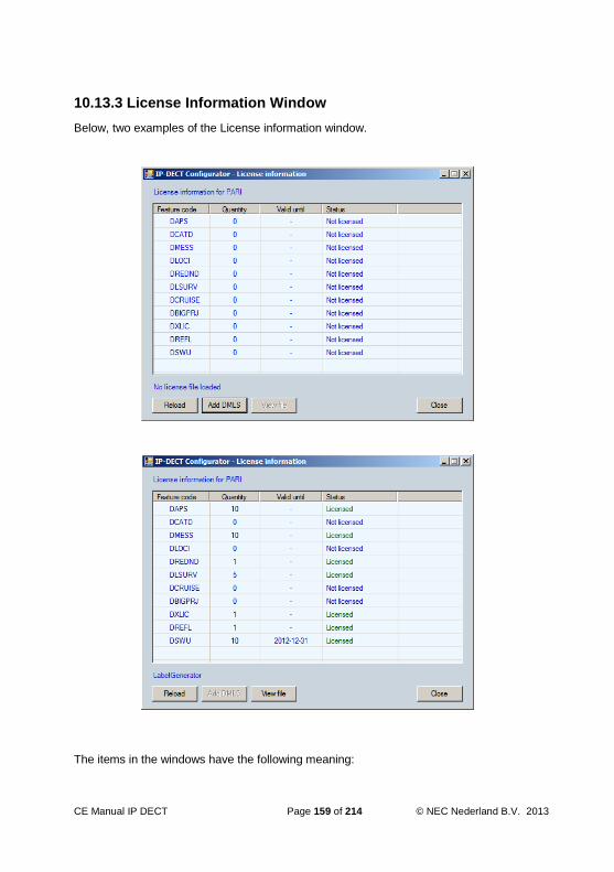
CE Manual IP DECT Page 159 of 214 © NEC Nederland B.V. 2013
10.13.3 License Information Window
Below, two examples of the License information window.
The items in the windows have the following meaning:

© NEC Nederland B.V. 2013 Page 160 of 214 CE Manual IP DECT SIP
ITEM EXPLANATION License Type
DAPS Number of DAPs allowed Number of DAPs in steps
of 10.
DCATD For Future use: CAT-iq Data allowed 0= no
1= yes
DMESS DECT Messaging allowed on DMLS. Number of DAPs in steps
of 10.
DLOCI DECT Messaging and Location allowed on
DMLS
Number of DAPs in steps
of 10.
DREDND DAP Controller Redundancy (Central DAP
Controller)
0= no
1= yes
DLSURV Survivability (Local DAP Controllers) 0 ... 10
DCRUISE Special functionality for Cruise Lines 0= no
1= yes
DBIGPRJ Special functionality for configurations with
more than 256 DAPs in one system with
seamless hand-over.
0= no
1= yes
DXLIC License for using the NEC ATEX
(ATmosphères EXplosives) handsets.
0= no
1= yes
DREFL Reflective environment license. Allows
additional settings for reflective
environments.
0= no
1= yes
DSWU DECT software upgrade license. Number of DAPs + expiry
date.
Note: Please note that the licenses DAPS, DMESS, DLOCI and DSWU are based on
the number of DAPs.
Note: Licenses that are based on the number of DAPs must always have the same
number of DAPs as licensed in the first item: DAPS. So, if the number of DAPS is
40, the other licenses (if required) that are based on the number of DAPs should
be forty as well. They cannot be less than the number of DAPs.

CE Manual IP DECT Page 161 of 214 © NEC Nederland B.V. 2013
Note: When you have a DMLS license for the DAP Controller License mechanism, the
license information is automatically copied into the DMLS, when the DMLS starts
up (make sure that you have the latest DMLS.)
When you have a DMLS license for the DMLS itself, (to import into the DMLS
directly), you can enter that license into the DAP Controller, by means of the
button “Add DMLS”.
© NEC Nederland B.V. 2013 Page 162 of 214 CE Manual IP DECT SIP
11 REDUNDANCY (General)
11.1 General
Redundancy in IP DECT can be necessary for the following functions:
Voice
Roaming
Messaging
It is important to determine which type of redundancy is required for your system.
In the following sections the redundancy for the functions is explained.
11.1.1 Voice Redundancy
To make voice connection redundant, Proxy Redundancy is required.
Proxy redundancy exists already for many years. When a SIP connection between a DAP
and a Proxy goes down or fails, the DAP can select another (redundant) Proxy. In the
DAP, you can set up a list of Proxy IP addresses with Priorities. For more information
about this type of redundancy, please consult Chapter 13. SIP PROXY REDUNDANCY
11.1.2 Roaming Redundancy
Handset roaming requires that the subscription record of the handset is always reachable
in one of the DAPs in the network. If not, the handset is not useable. In two cases,
roaming redundancy can be required:
DAP goes down.
When a DAP goes down, the subscription records in such a DAP are not reachable
anymore, and therefore the Handsets having a subscription record in that DAP, will
not be operational anymore. When the DAP Controller is up-and-running in the
network, it will take care that the subscriptions records will be put in another DAP
(after a short time). From that time on, the handsets are operational again. This
offers a high availability of the handsets. But, this means that the DAP Controller
must be up-and-running. To make this mechanism even more reliable, the DAP
Controller can be made redundant. (See Chapter 12 DAP Controller Redundancy).
Moving between Branch Office locations.
In a Branch Office configuration, the subscription record (in a DAP) moves with the
handset to another Branch Office (when the handset moves to the other Branch
Office). The DAP Controller takes care of this functionality. To make this mechanism
more reliable, the DAP Controller can be made redundant. (See Chapter 12 DAP

CE Manual IP DECT Page 163 of 214 © NEC Nederland B.V. 2013
Controller Redundancy).
11.1.3 Messaging Redundancy
DECT Messaging (LRMS) always goes via the DAP Controller. When there is only one
DAP Controller, it is a single point of failure for messaging. In certain environments,
messaging is an important functionality and must be highly reliable. Therefore it can be
necessary to have a Redundant DAP Controller configuration. The DAP Controller can be
made redundant, by means of adding second DAP Controller in the IP DECT System.
When LRMS is required in individual Branch Offices, you can install a Local DAP
Controller in the Branch Office, that takes care of the DAP Controller functionality in case
the connection to the Central DAP Controller(s) fail. Each Branch Office can have its own
Local DAP Controller. (See Section 12.4 Local DAP Controllers).
© NEC Nederland B.V. 2013 Page 164 of 214 CE Manual IP DECT SIP
12 DAP Controller Redundancy
Note: DAP Controller Redundancy is licensed!
12.1 General
DAP Controller Redundancy means that you will have one or more redundant DAP
Controller(s) in you network. If the main DAP Controller goes down, another DAP
Controller takes over the functionality.
Please note that there are various configurations possible.
Central DAP Controllers
A Central DAP Controller controls the entire IP DECT system, so the main site and, if
present, Branch Offices. As Central DAP Controller, there is always a Primary DAP
Controller and there can be a Secondary DAP Controller for redundancy. As a matter
of fact, the Secondary DAP Controller will take over when the Primary fails or is not
reachable anymore.
The maximum number of Central DAP Controllers is two.
For additional redundancy in Branch Office locations, there can be Local DAP
Controllers, see next bullet.
Local DAP Controllers
A local DAP Controller is located in a Branch Office, and controls its own Branch
Office in case the Central DAP Controller(s) cannot be reached anymore.
A Local DAP Controller never controls another Branch Office other than its own. So,
it operates in a Survivability mode for the Branch Office.
The maximum number of Local DAP Controllers is 10.
The distinction between a Central and a Local DAP Controller is determined by the
configuration that you setup in the “DAP Configurator” in the Primary DAP Controller.
Below, you see the DAP Configurator screen in which you must setup the configuration.
Please note that you assign the Central and the Local DAP Controllers here with the
associated priority.
So, for the Central DAP Controller(s), you specify a Primary (index 1) and if required, a
Secondary (index 2) DAP Controller.

CE Manual IP DECT Page 165 of 214 © NEC Nederland B.V. 2013
A special “service” (Redundancy Service) in the DAP Controller takes care of the
redundancy tasks.
Note: All configuration actions are done by means of the DAP Configurator in the
Primary DAP Controller. When done, the configuration must be exported from the
Primary to the other DAP controller(s)
12.2 DAP Controller Redundancy in Messaging Configuration
DAP Controller Redundancy in a messaging configuration, means that you have two DAP
Controllers and two DMLS services. Please note that in this description, we assume that
we have Central DAP Controllers (Primary and Secondary), and no Local DAP
Controllers. However, there could be a Local DAP Controller as well. (The characteristics
of the Local DAP Controller are explained in one of the following subsections.).

© NEC Nederland B.V. 2013 Page 166 of 214 CE Manual IP DECT SIP
The Messaging Application could have been duplicated as well, or it can have an IP
connection to each of the DMLS services.
The following figures show examples of the redundant configuration.
Figure 12-1 "Example of a Redundant IP DECT configuration with Messaging"
In the example above, there is only one IP DECT system, with two DAP Controllers, the
Primary and the Secondary. As you can see, there are two options: one messaging
system with two connections to the DMLS services, or duplicated Messaging Applications.
Note: The Duplicated Messaging Application must be capable to run in redundant mode
as well, one operational, one standby. Or in case of one Messaging Application, it
must be capable to handle two IP interfaces and detect which interface is
operational.
Note: In all cases, the Messaging application should check which DAP Controller and
therefore which DMLS is up and running.

CE Manual IP DECT Page 167 of 214 © NEC Nederland B.V. 2013
Message to the handsets when Primary DAP Controller is active
Figure 12-2 Messaging when Primary DAP Controller Active. Shows that, when the
Primary DAP Controller is active, the Messaging Application will send the message
to the DMLS (DMLS 1) that is connected to the Primary DAP Controller. The DMLS
will send the message to the Primary DAP Controller. The Primary DAP Controller
will issue a paging request via all DAPs in the system, to page the handset. When
the handset responds, the message is sent to the handset.
Figure 12-2 Messaging when Primary DAP Controller Active.

© NEC Nederland B.V. 2013 Page 168 of 214 CE Manual IP DECT SIP
Message to the handset when Primary DAP Controller is down.
Figure 12-3 Messaging when primary DAP Controller down. shows that, when the
Primary DAP Controller is down, the Messaging Application will send the message to
the DMLS (DMLS 2) that is connected to the Secondary DAP Controller. The DMLS
will send the message to the Secondary DAP Controller. The Secondary DAP
Controller will issue a paging request via all DAPs in the system, to page the
handset. When the handset responds, the message is sent to the handset.
Figure 12-3 Messaging when primary DAP Controller down.

CE Manual IP DECT Page 169 of 214 © NEC Nederland B.V. 2013
Message from the handset when Primary DAP Controller is active.
Figure 12-4 Message from handset when Primary DAP Controller is active.shows the
path of a message from a handset. It will go from the handset to the Primary DAP
Controller. Only if the Primary DAP Controller is down or not reachable, the DAP will
send the message to the Secondary DAP Controller (not shown in the figure.)
Figure 12-4 Message from handset when Primary DAP Controller is active.
Please note that the DAP determines where to send the message to: the Primary or the
Secondary DAP Controller. The DAP checks if the Primary DAP Controller is up-and-
running. If it is up-and-running, it will send the message to the Primary DAP Controller. If
not running, it will send the message to the secondary DAP Controller.

© NEC Nederland B.V. 2013 Page 170 of 214 CE Manual IP DECT SIP
12.3 DAP Controller Redundancy – How does it work
In the DAP Controller Redundancy, there is a Primary DAP Controller and a Secondary
DAP Controller. Please note that in an operational configuration, both DAP Controllers are
up-and-running. The Primary DAP Controller contains the actual and up-to-date
configuration. The Secondary DAP Controller keeps itself updated with the configuration
data from the Primary by means of a Presence Check and info exchange. See Figure
12-5 DAP Controller Redundancy.
Figure 12-5 DAP Controller Redundancy.
The DAPs select to which DAP Controller they will connect,
The DAPs select to which DAP Controller they will connect, based on the priorities in
the list of DAP Controllers. A DAP will try to connect to the DAP Controller that is first
in the priority list (Primary DAP Controller). If that fails, it will try to connect to the
second DAP Controller in the list (Secondary DAP Controller). If that fails it will try to
connect to the Local DAP Controller that is in the list (see the screen capture in
Section 12.1 General.).

CE Manual IP DECT Page 171 of 214 © NEC Nederland B.V. 2013
The Messaging Application.
In the Messaging Application configuration, most likely, one of the Applications is
operational, the other stand-by. The Messaging Application is able to detect if
Primary DMLS/DAP Controller is active or not. If operational, the primary Messaging
Application will be active. If the Primary DMLS/DAP Controller is not active, the
Messaging Application detects that, and will make the secondary Messaging
Application active.
When the Primary DAP Controller is down
If the Primary DAP Controller is down, the DAPs will notice that the DAP Controller,
is not operational anymore, and therefore, the DAPs will try to connect to the
Secondary DAP Controller, based on the on-board priority list of DAP Controllers.
See Figure 12-5 DAP Controller Redundancy. The Secondary DAP Controller
detects that the Primary is not reachable anymore, and will not allow to do any
manual changes in subscriptions anymore.
When the Primary DAP Controller becomes operational gain.
When the Primary becomes operational again, the following will happen:
The DAPs continuously poll the Primary DAP Controller to check if it is back again. Because of that, they will detect that the Primary DAP Controller is up again. Then they will “lock” on the Primary DAP Controller. Then the Primary DAP Controller will retrieve the configuration data (subscription data etc.) from the DAPs, to make the system consistent again.
The Secondary DAP Controller polls the Primary DAP Controller continuously. When it detects that the Primary DAP Controller is back again, it will request for configuration data from the Primary DAP Controller. The Primary DAP Controller already received the latest configuration data from the DAPs, and is up-to-date. The Secondary DAP Controller will get the configuration data from the Primary, and then the IP DECT System is consistent again.
What happens when there is a change in the configuration data in the Primary DAP Controller.
When there is a change in the configuration data in the Primary DAP Controller (e.g.
a handset is subscribed, the Redundancy Service in the Primary DAP Controller
sends a notification to all other DAP Controllers (Secondary and Local DAP
Controllers).

© NEC Nederland B.V. 2013 Page 172 of 214 CE Manual IP DECT SIP
12.4 Local DAP Controllers
Besides the Central DAP Controllers, there can be Local DAP Controllers. A Local DAP
Controller is located in a Branch Office and takes care of the DAP Controller functionality
in the associated Branch Office only, in case the Central DAP Controllers (Primary and/or
Secondary) are not reachable anymore. It performs a kind of Survivability task.
There can be up to 10 Local DAP Controllers.
The DAPs in the Branch Office will check if the Central DAP Controllers are reachable. If
not, they will check if the Local DAP Controller is reachable, and they lock on the local
DAP Controller.
Figure 12-6 Example of DAP Controller Redundancy with two Central DAP Controllers
and two Local DAP Controller. shows a configuration with mixed DAP Controllers, Central
and Local. Although capable to send/receive messages, the Local DAP Controllers are
not used for messaging in this example. However, if the Messaging Application supports
it, the Messaging Application could connect to a Local DAP Controller, to assure that
messaging works to the Branch Office.

CE Manual IP DECT Page 173 of 214 © NEC Nederland B.V. 2013
Figure 12-6 Example of DAP Controller Redundancy with two Central DAP Controllers and two Local DAP Controller.
12.5 Secondary DAP Controller in Branch Office location.
As a matter of fact, the Secondary DAP Controller does not necessarily have to be
located in the Head Quarter, but can be located anywhere else, e.g. in a Branch Office.
See Figure 12-7 Example of DAP Controller Redundancy with Secondary DAP Controller
in the Branch Office.
In this configuration the Secondary DAP Controller controls the entire IP DECT system
when the Primary DAP Controller fails. The Messaging Application can connect to the
Secondary DAP Controller, via the IP network.

© NEC Nederland B.V. 2013 Page 174 of 214 CE Manual IP DECT SIP
Figure 12-7 Example of DAP Controller Redundancy with Secondary DAP Controller in the Branch Office.
12.6 How to setup
PROCEDURE: “Setting up the Redundant Configuration”
Actions Make a drawing of the redundant configuration. Determine if you need to have a Secondary DAP Controller and determine if you need to have one or more Local DAP Controllers, and where in the network. If not yet done, open the DAP Configurator and go to “IP Settings” “DAP Controller IP Configuration”. Select Redundant DAP Controller. See the screen capture below.

CE Manual IP DECT Page 175 of 214 © NEC Nederland B.V. 2013
In the list of “Central DAP Controllers, enter the IP address of the Central, Primary DAP Controller in the row Index 1. If you have a secondary DAP Controller, enter the IP Address of the Secondary DAP Controller under Index 2 . If you have one or more “Local DAP Controllers”, enter the IP addresses in the table of the Local DAP Controllers. When done, click the Apply button and after that, the Save System button. Finish all other settings for the Primary DAP Controller. When done, click Export System and save the configuration in a file. Install the other (Central and or Local) DAP Controllers and Import the Configuration file from the Primary DAP Controller. Now you can start the DAP Controllers and the Redundant configuration should work. Check that the “Redundancy” service called “Redundant DAP Controller” is running as a service under Windows, and check that the “Redundant DAP Controller” service is set to “Automatic”.

© NEC Nederland B.V. 2013 Page 176 of 214 CE Manual IP DECT SIP
12.7 DECT Management
At the Primary DAP Controller
Normally you will do DECT Management on the Primary DAP Controller, and you will
have full DECT Management functionality available.
At the Secondary DAP Controller
When you open the WEB page on the Secondary DAP Controller with address
“Localhost”, you will be redirected to the Primary DAP Controller and you will have
full DECT Management functionality available. When the Primary DAP Controller is
not up-and-running, you will not be redirected, but you will see the Secondary DAP
Controller DECT Manager window in Read Only mode. When the Primary DAP
Controller comes back again, you will automatically be redirected to the Primary DAP
Controller.
12.8 How to Create an Archive
When you open a WEB Page on the Secondary DAP Controller, you will see the WEB
Page (DAP Manager screen) on the Primary DAP Controller. So, when you click the
Archive Button, an Archive is created of the Primary DAP Controller, but stored on the
Secondary DAP Controller!
When you want to make an Archive of the Secondary DAP Controller, you cannot do that
via the WEB Page (DAP Manager), unless the Primary DAP Controller is down. So, you
must use the button “Archive” in the DAP Configurator of the Secondary DAP Controller.
12.9 Actual Status Indication.
In the top right corner of the DECT Manager WEB interface, the Redundancy status is
displayed. The redundancy status is either Redundant or Stand Alone. See screen
capture below.
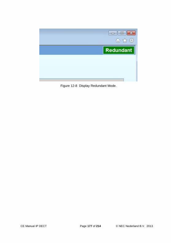
CE Manual IP DECT Page 177 of 214 © NEC Nederland B.V. 2013
Figure 12-8 Display Redundant Mode.

© NEC Nederland B.V. 2013 Page 178 of 214 CE Manual IP DECT SIP
13 SIP PROXY REDUNDANCY
13.1 Implementation
Redundancy means that a SIP User Agent (UA) can (automatically) register to a Proxy
out of a list of Proxies. Selection criteria (like availability of the Proxies) determine which
Proxy is chosen.
Complicating factors are related features like load-sharing, multi-tenancy and the fact that
DAPs can fail.
The implementation is based on a Proxy List. Each Proxy has specific properties in the list
like a priority level.
The following redundancy types are distinguished:
Fail Over
All UAs of one DAP, should register at the same primary Proxy. In case the Proxy
fails all UAs will register at the same secondary Proxy or when that fails to a tertiary
Proxy, etc. When the primary Proxy is back, all UAs should re-register at the primary
Proxy.
The first Proxy defined in the Proxy List is the primary Proxy, the second one the
secondary Proxy, etc.
At a certain interval, the DAP checks if the primary Proxy is back again. This is the
return-to-primary timer. The time period is specified in minutes.
Alternating
Two different Proxies are each other's standby. Either one of the Proxies is active. If
one fails, the other one becomes active. Therefore there is no primary nor secondary
Proxy.
The Proxy List contains just a list of Proxies and there is no priority. Also, there is no
timer needed to check if the other Proxy is back again.
Because no timer is needed, the “return-to-primary timer” is set to 0 minutes, which
means “disabled”.
Load-balancing
Several Proxies are capable of handling all UAs. When all Proxies are active, they
try to divide the registrations. When one fails, others will accept the registrations of
the failing Proxy.
Proxies in the Proxy List are associated with an extension number prefix, used as
discriminator to determine the primary Proxy.
At a certain interval, the DAP checks if the primary Proxy is back again. This is the
return-to-primary timer. The time period is specified in minutes.

CE Manual IP DECT Page 179 of 214 © NEC Nederland B.V. 2013
13.2 Selection Mechanisms
The following algorithms are used for selecting the preferred Proxy:
Selecting the Primary Proxy
The DAP searches from top to bottom in the proxy-list for the first Proxy that
matches the DNR prefix; a Proxy without DNR prefix always matches. If also a
domain name is assigned to this Proxy, the domain name is always used in each
message, also when registered at an alternative Proxy.
Selecting the Alternative Proxy
If the current or chosen Proxy does not accept the registration, the next Proxy that
matches will be chosen with the same domain name (irrespective of the DNR prefix,
an entry without domain name always matches); if not successful then restart at the
top of the proxy-list until the current one is reached again; If this still fails then after a
timeout the process starts all over again.
The following triggers will start searching for an alternative Proxy:
Registration Timer
The DAP re-registers the registered handset with the oldest expiry time for every
Proxy (with handsets registered at). The interval is not a fixed time but a computed
value. If a Proxy is not operational (doesn't answer upon 2 registration attempts) all
the handsets registered at that Proxy will try to re-register. If successful they will stay
registered at that Proxy. If not they will register at the next Proxy configured for that
handset. When also the next Proxy doesn't react, the search for an alternative Proxy
will be postponed and picked up by the regular registration process.
In this scenario worst case it will take 1 minute + the number of handsets per DAP *
5 seconds before all handsets will be registered at the secondary Proxy (if this Proxy
is up-and-running).
Return-to-Primary timer.
At the return-to-primary timer all handsets that are not active in a call and not
registered to their primary Proxy will try to re-register at their primary Proxy again. If
the registration is successful they will stay registered at the primary. Otherwise they
will re-register at their current Proxy. Handsets that are active in a call or handsets of
which the primary is not present have to wait for the next expiry of this timer before
another attempt to re-register them at the primary will be done.
Note that the value 0 means that the timer is disabled.
Note that with some extra configurations effort it is even possible to give DAPs at different
locations different configuration files and thus different Proxy lists.
The Proxy list must be entered in the DAP Configurator, in the “IP Settings” window.

© NEC Nederland B.V. 2013 Page 180 of 214 CE Manual IP DECT SIP
13.3 Examples
The following table shows some examples on how Proxy selection is done.
Example “Fail Over”
In this example the first Proxy is preferred. Each 4 minutes a primary check is done
(based on the timer value in the return-to-primary timer), to check if the primary
Proxy is back again.
The settings in the DAP Configurator “IP Settings” window are as follows:
Figure 13-1 "Example of Proxy settings required for the “Fail Over” example"
In this example, the timer settings in the DAP Configurator “SIP Settings” window
can be set to 4 minutes. See screen capture below as follows:

CE Manual IP DECT Page 181 of 214 © NEC Nederland B.V. 2013
Figure 13-2 "Example of Return to Primary setting for “Fail Over” example"
After saving the configuration, the following lines (amongst others) should be present
in the dapcfg.txt file:
[GK]
192.168.1.1 5060
192.168.1.2 5060
[XDS]
return-to-primary=4

© NEC Nederland B.V. 2013 Page 182 of 214 CE Manual IP DECT SIP
Example 2, Alternating
In this example, the first one that matches will be used until it fails. If it fails, the second one will be chosen. The second one remains selected until it fails.
The settings in the DAP Configurator “IP Settings” window are as follows:
Figure 13-3 "Example of Proxy settings required for the “Alternating” example"
The timer settings in the DAP Configurator “SIP Settings” window should be set to 0
seconds (to disable the timer), as shown in the screen capture below.

CE Manual IP DECT Page 183 of 214 © NEC Nederland B.V. 2013
Figure 13-4 "Return to Primary setting for “Alternating” example"
After saving the configuration, the following lines (amongst others) should be present
in the dapcfg.txt file:
[GK]
192.168.1.1 5060
192.168.1.2 5060
[XDS]
return-to-primary=0

© NEC Nederland B.V. 2013 Page 184 of 214 CE Manual IP DECT SIP
Example 3, Load Balancing
In this example, all extension numbers that start with 1 or 2 will have primary Proxy 192.168.1.1 and all other extension numbers will have primary Proxy 192.168.1.2. When the primary Proxy for the extension numbers that start with 1 or 2 is unreachable, Proxy 192.168.1.2 will be used. In this example, each 10 minutes a primary check is done to check if switching back to the primary Proxy is possible. This time is specified in the return-to-primary timer.
The settings in the DAP Configurator “IP Settings” window are as follows:
Figure 13-5 "Example of Proxy settings required for the “Load Balancing” example"
In this example, the timer settings in the DAP Configurator “SIP Settings” window
can be set to e.g. 10 minutes, as shown in the screen capture below.

CE Manual IP DECT Page 185 of 214 © NEC Nederland B.V. 2013
Figure 13-6 "Example of Return to Primary setting for “Load Balancing” example"
After saving the configuration, the following lines (amongst others) should be present
in the dapcfg.txt file:
[GK]
192.168.1.1 5060 0 1
192.168.1.1 5060 0 2
192.168.1.2 5060
[XDS]
return-to-primary=10

© NEC Nederland B.V. 2013 Page 186 of 214 CE Manual IP DECT SIP
Example 4, using different Domains
In this example, extension number ranges are in different domains. Extension numbers starting with a 1 will have:
test1.com as domain name.
Proxy 192.168.1.1 as primary.
Proxy 192.168.1.2 as secondary.
Proxy 192.168.1.3 as tertiary.
Extension numbers starting with a 2 will have:
test2.com as domain name.
Proxy 192.168.1.1 as primary.
Proxy 192.168.1.3 as secondary.
Each 10 minutes a primary check is performed.
The settings in the DAP Configurator “IP Settings” window are as follows:
Figure 13-7 "Proxy settings required for the “Using Different Domains” example”
The timer settings in the DAP Configurator “SIP Settings” window should be as
follows:

CE Manual IP DECT Page 187 of 214 © NEC Nederland B.V. 2013
Figure 13-8 "Return to Primary setting for “Using Different Domains” example"
After saving the configuration, the following lines (amongst others) should be present
in the dapcfg.txt file:
[GK]
192.168.1.1 5060 0 1 6 test1.com
192.168.1.1 5060 0 1 6 test1.com
192.168.1.1 5060 0 2 6 test2.com
192.168.1.3 5060
[XDS]
return-to-primary=10
Please note that there is a system type identifier as fifth field in the proxy definition
line. In this example the system type identifier is 6, which means SIP Proxy.

© NEC Nederland B.V. 2013 Page 188 of 214 CE Manual IP DECT SIP
Note: The selection criteria for a change over to a secondary proxy in the list is
primarily based on the domain specification. So, when the primary proxy fails, the
system will select the next proxy in the list that has the same domain name.

CE Manual IP DECT Page 189 of 214 © NEC Nederland B.V. 2013
14 USING OTHER TFTP SERVER
14.1 General
The previous sections assume that you are using the built in TFTP Server in the DAP
Controller/Manager Software. That is the easiest way because paths etc. are
automatically set correct. However, if you have chosen to use another TFTP server, paths
must be set correct and files needs to be copied into the TFTP root directory. Consult the
following section.
14.2 Prepare files for TFTP Upload to DAPs
The DAPs will only become operational if they can load the required files via TFTP. This
requires that the DHCP server and the TFTP server are up-and-running with the correct
configuration and it requires that the files for the DAP are available in the TFTP directory.
PROCEDURE: “Copying files to the TFTP directory”
Actions Determine which TFTP Server you are using. There are four options:
3com TFTP Server on this PC.
Windows TFTP Server on this PC.
Other TFTP Server on this PC.
Other TFTP Server running on other PC. In the following steps you must copy the firmware file (and configuration file) to the upload directory of the TFTP Server. Therefore, you must know the path settings of the TFPT Server that you are using. In the following table an overview is given of the TFTP Servers and the path settings.

© NEC Nederland B.V. 2013 Page 190 of 214 CE Manual IP DECT SIP
TFTP Server Default Path Preferred Path
3com C:\Documents and
Settings\All
Users\Application
Data\Nec\DAP
Controller\<system name>\
OR for Windows 7 and 2008:
C:\ProgramData\Nec\DAP
Controller\<system name>
C:\Documents and
Settings\All
Users\Application
Data\Nec\DAP
Controller\<system name>\
OR for Windows 7 and 2008:
C:\ProgramData\Nec\DAP
Controller\<system name>
Windows C:\tftpdroot\ C:\tftpdroot\
Other Unknown C:\Documents and
Settings\All
Users\Application
Data\Nec\DAP
Controller\<system name>\
OR for Windows 7 and 2008:
C:\ProgramData\Nec\DAP
Controller\<system name>
Other on other
PC
unknown unknown
Table 14-1 "Overview of TFTP Servers"
The two files that needs to be in the TFTP directory are:
Firmware file: 4910bvxx.dwl (the one that you have specified in Section 10.2
General Settings. The configuration file: dapcfg.txt.
Copy the firmware file to the TFTP directory of the TFTP Server that you are using.
If you are using the 3com TFTP server that came with the IP DECT installation
(default!) the default path equals the preferred path.
The dapcfg.txt file is by default stored in the directory: C:\Documents and
Settings\All Users\Application Data\Nec\DAP Controller\<system
CE Manual IP DECT Page 191 of 214 © NEC Nederland B.V. 2013
name>\. OR when you are using Windows 7 or Windows 2008, the directory is
C:\ProgramData\Nec\DAP Controller\<system name>. This is the default directory for the “3com TFTP” server that came with the installation of the IP DECT system. If you are using the “3com TFTP” server, no manual action is needed anymore. However, if
you are using another TFTP server, copy the dapcfg.txt from the directory C:\Documents and Settings\All Users\Application Data\Nec\DAP
Controller\<system name>\ to the TFTP directory that your TFTP Server is
using as upload directory. For Windows 7 or Windows 2008, the path is: C:\ProgramData\Nec\DAP Controller\<system name> Make sure that the option “Next Boot Server” in the DHCP Server that you are using, points to the IP address of the PC where your TFTP Server is running. The DAPs should be able to start-up now.

© NEC Nederland B.V. 2013 Page 192 of 214 CE Manual IP DECT SIP
15 OPENING DAP MANAGER WEB INTERFACE
You can open the DAP Manager window using Internet Explorer 6.0 or higher.
PROCEDURE: “Opening the DAP Manager WEB Interface”
Actions Open the MS Internet Explorer WEB browser on your DAP Controller/Manager PC. Enter an URL that points to the /CDS/ directory/file on the DAP Controller/Manager
PC.(e.g. http://127.0.0.1/CDS/)
It is also possible to open the WEB interface from another PC in the network. However,
you must know the right path. This could be e.g. http://192.168.4.80/CDS/,
where “192.168.4.80” is the IP address of the DAP Controller/Manager PC. Now, you should see the "DECT Manager" main screen. If not, then check if your IIS is running on the DAP Controller/Manager PC. Also check if the default.aspx file is
present in the C:\Inetpub\wwwroot\CDS directory.
If you have a licensed configuration, assign licenses to your IP DECT system via the DECT Manager interface.
Note: The DECT Manager interface is described in the IP DECT Manager
Administrator Guide.
Enter the extension number range via the DECT Manager interface. Check that the DAPs are operational. Subscribe the handsets. Check that you can make phone calls.

CE Manual IP DECT Page 193 of 214 © NEC Nederland B.V. 2013
16 PORTABLE SHARING
16.1 What it is
Portable Sharing allows the user to give the portable (handset) an extension number via a
“login” procedure.
When a portable is enabled for Portable Sharing, you will get a “Login” message when
you go off hook after one of the following conditions:
after the handset was subscribed.
after the handset was switched on.
after the handset was taken from the charger with silent charging switched on.
In this “login” mode, you must enter the extension number that you want to activate for the
handset. This extension number must already be present in the SIP Proxy. After you
entered the extension number, you must terminate the login with a closing digit. By
default, “#” is the closing digit. However, this can be changed. After entering the closing
digit, the handset is active for the extension number that you have entered. Only after a
“logout” the handset displays the “login” again.
How and when does a handset a Logout? A Logout is executed automatically, when the handset sends a “Detach” signal to the DECT System. Sending a “Detach” signal is done automatically at the following manual action:
Switching off the handset
The handset types G355, G955, I755, ML440 and later types, will send a “Detach”
signal when they are within reach of the IP DECT system AND when the user
switches off the handset!
Putting the handset in charger with silent charging enabled.
The handset type G355, G955, I755, ML440 and later types, will send a “Detach”
signal when they are within reach of the IP DECT system AND when the user puts
the handset in the charger in silent charging mode.
Note: When any type of handset goes out of range, no Detach signal is sent!
Therefore “login” is not activated when the handset comes within range
again.
Note: This Portable Sharing mechanism is supported for G355, G955, I755, ML440
and later types. On other types of handsets, support of Portable Sharing is
not available at all, or you can login only once because there is no “Detach”
possible.
Portable Sharing is disabled by default for the IP DECT system, but can be switched on
using the DAP Configurator.

© NEC Nederland B.V. 2013 Page 194 of 214 CE Manual IP DECT SIP
When enabled, you must designate a certain number range in the subscription numbers
that is used for Portable Sharing. The numbers in this range may NOT exist as extension
numbers in the SIP Proxy. These numbers must start with the same “prefix”. This prefix
must be specified in the DAP Configurator and could be e.g. “00”.
16.2 Portable Sharing and the DAP Manager
The DAP Manager PC is always needed for handling the Login information and for
providing the login information to the DAPs (e.g. when a DAP restarts). This means that
the DAP Manager should always be connected and should be up-and-running. However,
it is not “Single point of failure”, which means that if the DAP Manager is down you can
still make and receive calls.
The login information is stored in a file dds-login.txt on the hard disk of the DAP
Manager PC.

CE Manual IP DECT Page 195 of 214 © NEC Nederland B.V. 2013
APPENDICES

© NEC Nederland B.V. 2013 Page 196 of 214 CE Manual IP DECT SIP
A UPGRADE TO LATEST RELEASE
To upgrade to the latest release of the DAP Controller software consult the IP DECT
Advanced Data Manual.

CE Manual IP DECT Page 197 of 214 © NEC Nederland B.V. 2013
B AP300 Versus AP200
B.1 Overview of Differences
From November 2009 onwards a new DAP will be introduced, the AP300 as a successor
of the AP200.
In this Appendix you will find an overview of the differences between the AP200 and the
AP300.
Notes: For more information on the characteristics of the AP300, please consult the
AP300 Installation Manual.
Differences are as follows:
Main differences:
ITEM AP200 AP300
Compact Size A5 2/3 of A5
Mounting Vertical Vertical or Horizontal
Localization support
Various types One type of AP300 suitable for all regions. Country and region selection in the DAP Configurator.
G.729 AP200 only, not in AP200S.
Available via daughter board on the AP300. See Section C “AP400 Versus AP300
Overview of Differences
From June 2012 onwards the AP400
will be introduced, as a successor of
the AP300.
In this Appendix you will find an
overview of the differences between
the AP300 and the AP400. Please
note that the AP300 and the AP400
are similar in many aspects. .
”.
Power supply Local via AC adaptor PoE IEEE802.3af.
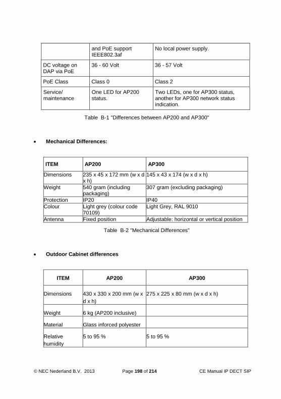
© NEC Nederland B.V. 2013 Page 198 of 214 CE Manual IP DECT SIP
and PoE support IEEE802.3af
No local power supply.
DC voltage on DAP via PoE
36 - 60 Volt 36 - 57 Volt
PoE Class Class 0 Class 2
Service/ maintenance
One LED for AP200 status.
Two LEDs, one for AP300 status, another for AP300 network status indication.
Table B-1 "Differences between AP200 and AP300"
Mechanical Differences:
ITEM AP200 AP300
Dimensions 235 x 45 x 172 mm (w x d x h)
145 x 43 x 174 (w x d x h)
Weight 540 gram (including packaging)
307 gram (excluding packaging)
Protection IP20 IP40
Colour Light grey (colour code 70109)
Light Grey, RAL 9010
Antenna Fixed position Adjustable: horizontal or vertical position
Table B-2 "Mechanical Differences"
Outdoor Cabinet differences
ITEM AP200 AP300
Dimensions 430 x 330 x 200 mm (w x
d x h)
275 x 225 x 80 mm (w x d x h)
Weight 6 kg (AP200 inclusive)
Material Glass inforced polyester
Relative
humidity
5 to 95 % 5 to 95 %
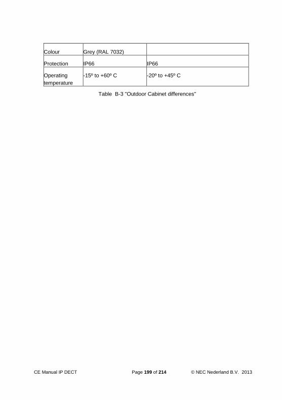
CE Manual IP DECT Page 199 of 214 © NEC Nederland B.V. 2013
Colour Grey (RAL 7032)
Protection IP66 IP66
Operating
temperature
-15º to +60º C -20º to +45º C
Table B-3 "Outdoor Cabinet differences"
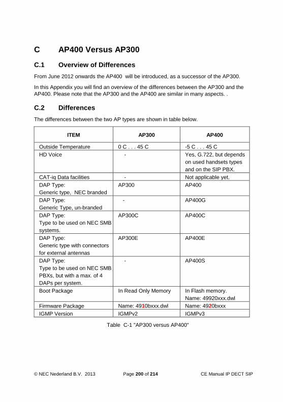
© NEC Nederland B.V. 2013 Page 200 of 214 CE Manual IP DECT SIP
C AP400 Versus AP300
C.1 Overview of Differences
From June 2012 onwards the AP400 will be introduced, as a successor of the AP300.
In this Appendix you will find an overview of the differences between the AP300 and the
AP400. Please note that the AP300 and the AP400 are similar in many aspects. .
C.2 Differences
The differences between the two AP types are shown in table below.
ITEM AP300 AP400
Outside Temperature 0 C . . . 45 C -5 C . . . 45 C
HD Voice - Yes, G.722, but depends
on used handsets types
and on the SIP PBX.
CAT-iq Data facilities - Not applicable yet.
DAP Type:
Generic type, NEC branded
AP300 AP400
DAP Type:
Generic Type, un-branded
- AP400G
DAP Type:
Type to be used on NEC SMB
systems.
AP300C AP400C
DAP Type:
Generic type with connectors
for external antennas
AP300E AP400E
DAP Type:
Type to be used on NEC SMB
PBXs, but with a max. of 4
DAPs per system.
- AP400S
Boot Package In Read Only Memory In Flash memory.
Name: 49920xxx.dwl
Firmware Package Name: 4910bxxx.dwl Name: 4920bxxx
IGMP Version IGMPv2 IGMPv3
Table C-1 "AP300 versus AP400"

CE Manual IP DECT Page 201 of 214 © NEC Nederland B.V. 2013
D SIP CONFIGURATION CHARACTERISTICS
D.1 General
Setting up the SIP configuration requires basic SIP knowledge. Make sure that you have
basic SIP knowledge before continuing this Chapter and the Chapters that follow. The SIP
implementation differs between the various types of SIP Proxy/Registrar servers. It is
important to know the basic characteristics of the SIP Proxy/Registrar server to which you
want to connect the SIP IP DECT system.
In the following Sections, the Business Mobility IP DECT SIP characteristics are
described. This can be useful before you continue with the installation. However, if you
are familiar with the SIP characteristics of the Business Mobility IP DECT system,
continue with the installation of the Business Mobility IP DECT system, see Chapter 8
“INSTALLING THE DAP Controller/Manager” and onwards.
D.2 Main Characteristics
The following overview shows the main SIP characteristics of the Business Mobility IP
DECT system:
Connectivity
The Business Mobility IP DECT system can be connected to many SIP types of
commercial, open-source or freeware SIP Proxy server, SIP Registrar server, SIP
Gateways, SIP IP-phones, SIP soft phones, SIP IP enabled PBX’s etc.
The Business Mobility IP DECT system can also be connected directly to a DSL line
for small branch and home offices.
SIP Extension Registration
Usage of SIP Registrar server is supported (optional).
Detached portables are unregistered from the SIP registrar server. (Portables
can be detached automatically, when they support sending a “Detach” signal
and “switches off”. Also when they support “Detach” signal and put in the
charger in “Silent Charge” mode a Detach signal is send.
Digest authentication security.
SIP URL configurable: sip:phone-number@ip-address e.g.
sip:[email protected] or sip:”phone-number”@host-domainname e.g.
sip:[email protected].
Username and/or password configurable.
Transmission
High quality voice over IP, G.711 when the call remains within the LAN
segment, or G.711/G.729 when the peer-to-peer connection crosses a router in
a Branch office configuration. However, you can select whether you want to use
G.729 only, or never use G.729.
Congestion control and packet filtering.
Reliable UDP transport using retransmissions.

© NEC Nederland B.V. 2013 Page 202 of 214 CE Manual IP DECT SIP
D.3 Call Handling
In the following table the SIP call handling features are given.
Feature Reference
Basic Call RFC3261 (except for TCP, IP, Multicastr. MIME and authentication)
Negotiation of most efficient CODEC based upon network information.
Supported CODECs:
G.711 a-Law
G.711 u-Law
G.729
RFC 2327 RFC 3264
Payload negotiation. Supported payload values: 20 ,30, 40, 50, 60 msec.
RFC 2327 RFC 3264
En-block (pre-dial) and overlap dialling RFC 3578
Remote name, or if not available, phone number is displayed on the handset.
Discrimination between internal and external calls based upon extension number length (configurable)
Established session modification (re-INVITE)
Call hold using re-INVITE
Shuttle between two parties.
Call transfer:
Attended call transfer using REFER, Refer-To and Replaces
Unattended call transfer using REFER and Refer-To
RFC 3515 RFC 3891
DTMF digit sending:
Via SIP INFO messages
In RTP stream
- RFC 2976 RFC 2833
SIP Music-On-Hold
When connected to a FXO gateway, it switches to transparent mode to save trunk lines
Instant Messaging to and from SIP-DECT portables RFC 3428 (protocol supported, no application implemented)
MWI (Message Waiting Indication) RFC 3842
Table D-1 "Supported SIP Features"

CE Manual IP DECT Page 203 of 214 © NEC Nederland B.V. 2013
D.4 Configurable Items in IP DECT SIP
The following table gives an overview of the items that can be configured in the SIP IP
DECT configuration, in order to adapt to the SIP Proxy Server and, if present, SIP
Registrar. Note that this gives an overview only, the actual settings must entered during
the installation of the Business Mobility IP DECT software when asked for. It is always
possible to change the settings after the installation.
Parameter Default Value Description
proxy_address no default The IP address of the Proxy server
proxy_port 5060 The port number on the Proxy server
registrar_addr [proxy_address] The IP address of the Registrar server. IP4, dotted format. If nothing specified, this address is equal to the specified Proxy server address.
registrar_port [proxy_port] The port number on the Registrar server. If nothing specified, this address is equal to the specified Proxy server address.
sip_domain [proxy_address] SIP Domain. If nothing specified, this address is equal to the specified Proxy server address.
max_intern_dnr_len 6 Extension numbers longer than this value, are considered as “extenal”. Only applicable for nummeric extension numbers.
local_port 5060 Local SIP port on the DAPs.
realm1 ... realm5 [empty] Up to five authentication realms (for both, www and Proxy) can be specified.
user1 ... user5 [empty] Up to five authentication users (for both, www and Proxy) can be specified. Note: in case “%s” the DNR (extension number) will be used instead.
passw1 ... passw5 [empty] Up to five authentication passwords (for both, www and Proxy) can be specified.
sdp_late_sendrecv no Enables/disables the ability of the SIP DECT to issue an initial invite without SDP offer.

© NEC Nederland B.V. 2013 Page 204 of 214 CE Manual IP DECT SIP
Parameter Default Value Description
sdp_rfc3264 yes Enables/disables “Hold” according to RFC3264
sdp_MoH no When enabled, no local tone is generated when DECT portable is put in “recv only” (hold) mode.
sdp_payload_size 20 Offered payload size in SDP offer (in msec.) However, the proposed payload size of the other party is used.
sdp_DTMF_rfc2833 no When enabled, DTMF digits are sent according to RFC2833 (in RTP). Otherwise, the DTMF digits are sent as SIP INFO messages.
mwi_support no Enables/disables Message Waiting Indication.
Table D-2 "Configurable Items in SIP IP DECT"

CE Manual IP DECT Page 205 of 214 © NEC Nederland B.V. 2013
E LRMS MESSAGING
E.1 General
Note: Messaging can only be used with handsets that support LRMS (E2) messaging.
IP DECT supports LRMS (Low Rate Message Services). There are two options:
Handset - handset Messaging
This means that handsets can send messages between each other.
Depending on the connection to the Messaging Server, and depending on the SIP
Messaging setting, handset to handset messaging is possible or not.
Messaging Server - Handset Messaging
You can connect a Messaging Server to IP DECT to send and receive messages
to/from handsets. The DAP Controller offers an interface for Messaging to and from
handsets. However, the DAP Controller supports a proprietary protocol, which
requires a converter program called: DMLS (DECT Messaging and Location
Services). The DMLS offers a rich, yet simple, interface for Third Party Messaging
servers.
For more information about Messaging Server applications, please contact your IP
DECT supplier.
The following figure shows the message path between a Messaging Server and IP
DECT.

© NEC Nederland B.V. 2013 Page 206 of 214 CE Manual IP DECT SIP
Figure E-1 Message path in IP DECT - Messaging Server configuration
Note that the messaging between the Messaging Server and IP DECT, always goes
via the DAP Controller/Manager. It is an TCP/IP connection. The TCP port for
messaging on the DAP Controller/Manager is always the lowest port number + 1
(default 28001). The moment that there is a connection to this port, all messages will
be handled by the Messaging Server and handset to handset messaging is only
possible via the Messaging Server.
Note: When the option “Local Message Relay Override” is selected in the DAP
Configurator, the Messaging Server can send messages to handset and
handset to handset messaging is still possible.
Note: When the SIP option “SIP Messaging” is enabled in the IP DECT
Configurator, all messages will go via the SIP interface (SIP instant
messaging) and not via the DAP Controller. SIP messaging does not support
Normal, Urgent and Emergency messages (see section E.2 “Types of
Messages”) and it does not support broadcast messaging. (see section E.3
“Broadcast Messaging”)
Messaging Server - Handset Messaging with Local Message Relay Override
In the DAP Configurator, there is an option “Local Message Relay Override”. When
you activate this option, you can send messages between handsets and the
Messaging Server can send messages to handsets. Note that you cannot send

CE Manual IP DECT Page 207 of 214 © NEC Nederland B.V. 2013
messages from handsets to the Messaging Server when “Local Relay Override” is
active.
E.2 Types of Messages
When sending a message to a handset, there are three types of messages distinguished.
The message types indicate the emergency level.
Normal Message
When this type of message is send to a handset, the handset displays the message
and will alert with a short ringing. The user of the handset cannot confirm the
message. The handset sends back a technical “ACK” to the originator of the
message (e.g. DECT Server) to indicate that the message arrived on the handset.
Urgent Message
When this type of message is sent to a handset, the handset displays the message
and alerts with a ringing type that gets louder and louder until the handset user
confirms the message (or a timer expires). The user can confirm the message by
pressing the “OK” button or the “Delete” button. When the message is send to the
handset, a timer is started. The user must confirm the message within the time
period of the timer (default 30 sec.). If not confirmed within this time, ringing stops
and a “NACK” is send to the originator of the message, to indicate that the user
didn’t confirm the message.
Emergency Message
When this type of message is send to a handset, the handset displays the message
and alerts with a very compelling ringing type. This forces the user to confirm the
message by pressing the “OK” button or the “Delete” button. Confirmation must be
done within a certain time period, which is the same as for an Urgent message. (Also
30 seconds by default.) If not confirmed within this time, ringing stops and a “NACK”
is send to the originator of the message, to indicate that the user didn’t confirm the
message.
The originator of the message determines the urgency type of the message. Note that if
the handset is the originator, there are only two message types possible: Normal and
Urgent. When the Messaging Server is the originator, three message types are possible:
Normal, Urgent, Emergency.
E.3 Broadcast Messaging
E.3.1 General
Broadcast Messaging is implemented from IP DECT Release 4.2 onwards. Broadcast
messaging will normally be used in case of an emergency situation where a large group
of people needs to be reached in a very short time.
© NEC Nederland B.V. 2013 Page 208 of 214 CE Manual IP DECT SIP
Broadcast Messaging has the following characteristics:
It uses a kind of “connection-less” data transfer.
To improve message delivery, the Messaging Server can repeat the message a few
times. The handset will ignore duplicate messages.
Neither the portable nor the end-user can confirm reception of the message.
No traffic bearers are occupied. This avoids congestion.
Note: The maximum message length is 54 characters.
Note: Broadcast Messaging is optional in IP DECT. It must be enabled using the DAP
Configurator tool.
Broadcast messaging works with groups. If a handset is member of a group, it is capable
of receiving messages for that group. Note that all handsets are always part of the default
group (“000”).
E.3.2 Additional Broadcast Message Types
There are three (additional) message types defined for broadcast messaging. The
Message Server must be capable of sending these messages, because the handset is
not able to send broadcast messages, it is only able to receive broadcast messages.
Broadcast Messages
A Broadcast message is a real message which is addressed to a group of portables.
A three digit number identifies the group. (A handset must have been made member
of a group before it can receive messages for the group.)
All portables that support broadcast messages are automatically member of the
group ‘000’. Next to this group a portable can be member of 5 other groups.
Note that these messages are not acknowledged. Therefore it is possible that a
portable did not receive this message, because it was for instance out of reach,
powered down, in silence charging mode or because of bit-errors in the air. It is the
responsibility of the Messaging Server to repeat the same message, to get a higher
chance of correct reception by all portables.
Although these messages are not acknowledged, it is still useful to distinguish
between normal, urgent and very urgent broadcast messages, because it determines
also how the message is presented to the user.
Group Membership
This is not a user message send to the display of the handset. It is a membership
message send to the handset. A message Server can instruct a portable to become
member of a group or give-up membership of a group by means of this message
type. It is also possible to instruct a portable to give-up membership of all groups
except ‘000’.
It is the responsibility of the messaging server to keep track of the group
membership of each individual portable, since a portable has to acknowledge this

CE Manual IP DECT Page 209 of 214 © NEC Nederland B.V. 2013
type of message.
Broadcast Group Membership
(This is not a user message send to the display of the handset.) By means of this
type of message a Messaging Server can instruct a group of portables to give-up
membership of one group or all groups (except of course of group “000”.) Note that
these messages are not acknowledged.
Note; Group Membership arrangement is the task of the Messenging Server. IP DECT
only forwards the group membership messages to the handsets.
E.3.3 How about Normal, Urgent, Emergency Messages
Sending a broadcast message to a handset still supports urgency levels: Normal, Urgent
and Emergency. However, there is no B-channel used and there is no acknowledge send
back.
Using broadcast messaging the behaviour of Normal, Urgent and Emergency messages
is as follows:
Normal Broadcast Message
A normal broadcast message appears on the handset as if it is a normal message.
The difference is a technical difference. In case of a normal unicast message the
handset will respond and an ACK is sent to the Messaging Server.
Urgent broadcast Message
When the handset receives a broadcast Urgent message, it appears on the handset
as if it is unicast Urgent message. The ringing rhythm is the same. To stop the
ringing, the handset user has to acknowledge the message by means of pressing the
“OK” or “Delete” button. Note that pressing this button does NOT send a confirmation
to the system, it only stops ringing. If the user does not press the “OK” or “Delete”
button, the handset will terminate the ringing when a timer in the handset expires.
This timer is always longer that 30 seconds and normally shorter than one minute.
The time value may be different per handset type.
Urgent and Emergency broadcast Message
When the handset receives a broadcast Emergency message, it appears on the
handset as if it is unicast Emergency message. The ringing rhythm is the same. To
stop the ringing, the handset user has to acknowledge the message by means of
pressing the “OK” or “Delete” button. Note that pressing this button does NOT send a
confirmation to the system, it only stops ringing. If the user does not press the “OK”
or “Delete” button, the handset will terminate the ringing when a timer in the handset
expires. This timer is always longer that 30 seconds and normally shorter than one
minute. The time value may be different per handset type.
© NEC Nederland B.V. 2013 Page 210 of 214 CE Manual IP DECT SIP
E.4 SIP Messaging and DASGIF Messaging (IP DECT Rel. 5.00_401 or higher)
SIP Messaging and messaging via the DASGIF interface are available in IP DECT. It is
important to know how this works together.
When IP DECT is connected to a SIP Proxy that supports SIP Messaging, you can select
whether you want to use LRMS or SIP Messaging. It is an option in the DAP Configurator.
When you select “SIP Messaging”, the messages from the handset are sent from the DAP
where the subscription record resides to the SIP Proxy instead of to the DAP
Controller/Manager. It uses SIP instant Messaging. The opposite way around, the SIP
Proxy can send messages straight to the DAP where the subscription record resides. This
means that the DAP Controller/Manager is not involved in the SIP Messaging.
In a mixed configuration, the following OUTBOUND messaging is supported:
From SIP Proxy to DAP
Using the SIP instant Messaging - SIP Method “MESSAGE”.
From External Messaging Application to the DAP Controller
From External Messaging Application to the DAP Controller. In the External
Messaging Application, there is the Application Interface component called CTI or
DMLS as interface between the Messenger Application and the DASGIF interface to
the DAP Controller.
Note: Both incoming messages as mentioned above, will always work, independently of
settings in IP DECT.
In a mixed configuration, the following INBOUND messaging is supported:
When a handset sends a message, the destination of the message is determined by a
number of conditions. This is shown in Figure E-2 "Outbound Messaging from Handset".

CE Manual IP DECT Page 211 of 214 © NEC Nederland B.V. 2013
Figure E-2 "Outbound Messaging from Handset"

© NEC Nederland B.V. 2013 Page 212 of 214 CE Manual IP DECT SIP
F SV8100/SL1100/SL1000 Abbreviated Dial Sharing for Central Directory Access
F.1 General Info
It is possible to access the SV8100/SL1100/SL1000 Abbreviated Speed Dial list on certain IP DECT handsets and search the list by name. The programming procedure consists of two parts: -Program the TCP port number in the PBX -Program the IP DECT system with the PBX IP address and specified port number in the Central Directory configuration area.
F.2 Programming the PBX TCP Port
1. Connect to the PBX using the PC Programming tool by going to the Communication menu and selecting Connect.
2. Download the PBX data to PC Pro. 3. Using the Wizards navigate to Advanced Items>IP DECT>IP DECT
Setup. 4. Enter the required TCP Port against the IP-DECT Directory Access
(30160 recommended). 5. Click Apply. 6. Upload the new settings to the PBX. 7. Disconnect PC Pro.
F.3 Programming the IP DECT system
1. IP DECT must also be configured to reach the Central Directory Access services. Open the DECT configurator, select the required configuration and click Modify System.
2. Click the IP Settings button and then click the CDA IP Configuration tab. The following window should be displayed.
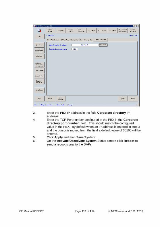
CE Manual IP DECT Page 213 of 214 © NEC Nederland B.V. 2013
3. Enter the PBX IP address in the field Corporate directory IP
address: 4. Enter the TCP Port number configured in the PBX in the Corporate
directory port number: field. This should match the configured value in the PBX. By default when an IP address is entered in step 3 and the cursor is moved from the field a default value of 30160 will be entered.
5. Click Apply and then Save System. 6. On the Activate/Deactivate System Status screen click Reboot to
send a reboot signal to the DAPs.

© NEC Nederland B.V. 2013 Page 214 of 214 CE Manual IP DECT SIP
G OVERVIEW OF DEFAULT USED IP PORTS
The following table gives an overview of the default ports used in a Business Mobility IP
DECT configuration.
Protocol Interface/Device Default Destination port
DHCP DHCP Server 67
DAP 68
Proprietary IP DECT protocol and messaging
(port 28001).
DAP Controller 28000-28017
IP DECT Proprietary signalling (IP Unicast and IP Multicast), SIP
Protocol and RTP (Real Time Protocol)
DAP 3000-22635
TFTP TFTP Server 69 (only for initial communication)
then:1024-65535
Table G-1 "Default ports used in Business Mobility IP DECT"


