1 4/4/2011 Team Members Bryant Barnes Addney Biery Paul List Matthew Plachta Advisor Russell Clark Faculty Advisor Statement I certify that the engineering design of the vehicle described in this report, KITT, has been significant, and that the student effort was a senior design capstone project. SVSU K.I.T.T. KINEMATIC INTELLIGENT TACTICAL TECHNOLOGY
Transcript
1
4/4/2011
Team Members Bryant Barnes
Addney Biery
Paul List
Matthew Plachta
Advisor Russell Clark
Faculty Advisor Statement I certify that the engineering design of the vehicle described in this report, KITT, has been significant,
and that the student effort was a senior design capstone project.
SVSU K.I.T.T.
KINEMATIC INTELLIGENT TACTICAL TECHNOLOGY
2
1. Abstract
The Intelligent Ground Vehicle Competition is held at Oakland University each year.
The group designed a vehicle that could navigate autonomously through various courses
in the allocated amount of time. The vehicle had to meet competition specified
requirements which include: overall size, safety requirements, and speed requirements.
This project is the pinnacle of a compilation of four years of electrical engineering design
theory applied to a real life application.
2. Introduction
The development of vehicles capable of navigating autonomously has been an
area of increasing focus over the past few years. Autonomous functions have long ago
been incorporated into aircraft technology, while incorporation into the automotive
industry has been much slower. This disparity is due in large part to the complexity of
ground navigation as it relates to determining the proper destinations and paths. When
driving a car most decisions are based on interpretation of visual data. These decisions
are relatively simple to teach a human being, but are more complex when implemented
by a computer. The difference between a driveway and a boat launch may be fairly
obvious to a person, but communicating such differences to a computer control system
is much more difficult. The ability to navigate in any form involves the ability to sense
the environment and knowledge of position in respect to the destination. For aerial
vehicles this involves the knowing the position and heading of the vehicle, knowing the
location of the destination, and the ability to detect and avoid obstacles. With ground
vehicles the added visual component is necessary in order to navigate effectively.
Interpretation of visual data through computer logic often involves the development of
algorithms that perform advanced pattern recognition techniques in order to identify
3
objects that the average human-being could easily identify. The designs developed as
part of project KITT utilize rudimentary vision techniques in addition to other necessary
sensors in order to create an autonomously navigating ground vehicle.
The goal of the KITT project was to consider a simple case where the vehicle
need only to avoid obstacles while staying within boundaries outlined by lines of
different color than the course. A key motivation for this project was to prepare a
vehicle that abides by the rules and specifications of the Intelligent Ground Vehicle
Competition (IGVC) held annually at Oakland University in Rochester, Michigan. This
competition provides a venue for teams from universities across the United States and
abroad to test the design and processing of small-scale autonomous vehicles. The
demands of this competition were used as a guideline for construction and operation of
the KITT project. The IGVC has detailed descriptions of the challenges available at the
competition. From these descriptions basic requirements were developed that the
vehicle must be able to navigate using GPS coordinates while avoiding obstacles and
staying within boundaries. Sensors were chosen that would provide the necessary data
to the vehicle for completion of the IGVC challenges. Much of the design involved in this
project entailed communication with and interfacing of the various sensors, controllers,
and components. Another major aspect of the project was developing the search
algorithm to navigate the vehicle. The operation of KITT's major components as well as
details of the hardware and software designs used for this project are provided in this
report.
3. Design
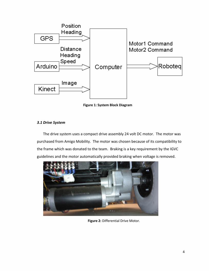
Below is a block diagram of the entire system used for the vehicle. On the left hand of the
diagram are the inputs of the system, which include a digital compass, a GPS, and an Xbox
Kinect. The output is heading to the motor controller as two commands, one for speed and one
for direction.
4
Figure 1: System Block Diagram
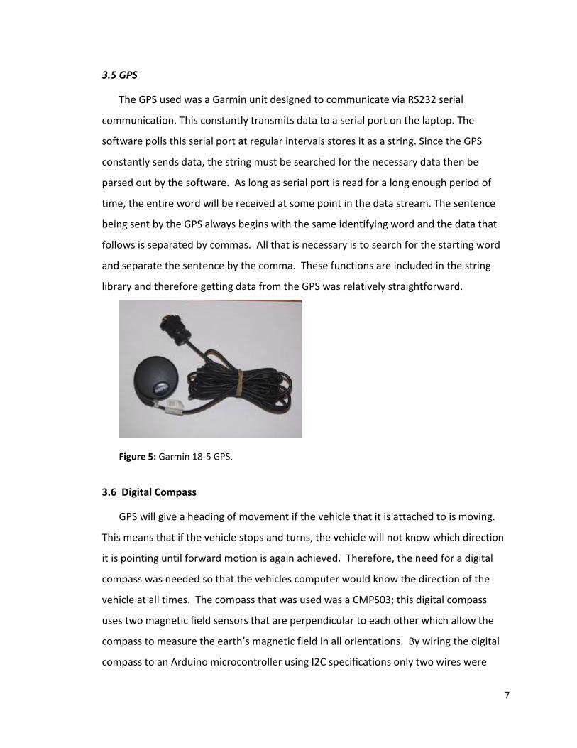
3.1 Drive System
The drive system uses a compact drive assembly 24 volt DC motor. The motor was
purchased from Amigo Mobility. The motor was chosen because of its compatibility to
the frame which was donated to the team. Braking is a key requirement by the IGVC
guidelines and the motor automatically provided braking when voltage is removed.
Figure 2: Differential Drive Motor.
5
3.2 Steering System
The steering system uses a Dayton 12 volt DC motor. The motor was used because it
was configured with an encoder and was free because it was taken from an old project.
The steering system is connected to a DC motor controller which is controlled through
software in order to adjust the heading of the vehicle.
Voltage: 12V
Horsepower: 1/5
Amps: 18.5
RPM: 80
Torque: 135 in*lb
Ratio: 20 to 1
Figure 3: Steering Motor
3.3 Batteries
Absorbed Glass Mat (AGM) batteries were chosen. An AGM battery is spill proof
and considered the most vibration and impact resistant batteries available. These
batteries also have the advantage of needing no maintenance. This means two things:
first, battery acid never has to be added; and second, if the charging is not controlled
the battery would be destroyed.
Since there are both 12-volt systems and 24-volt systems, it was necessary to have
two battery banks. The 24-volt system that powers the motor controller as well as the
motors consisted of two 33Ah AGM-lead acid batteries. The 12-volt system powers
everything else aside from the computer and consists of a single 33Ah AGM-lead acid
battery.
6
3.4 Motor Controller
The motor controller is responsible for controlling the responses of both the drive
motor and the steering motor that allow the vehicle to move and turn. The controller
used for this project is the Roboteq AX2550. This controller has many useful features
including the ability to operate both the steering motor and drive motor. One key trait
of the Roboteq controller is the ability to communicate directly to the computer through
RS232 serial protocol. The controller is able to both receive commands and send data
about the current operation back to the computer. The commands used to control the
motors are simple one-line commands. A program was written that uses these motor
commands in order to execute turns and linear motion. Two different methods of
turning were considered: one in which the next position was given in coordinate form
and the necessary turning radius and turn distance were calculated. The second method
utilizes the digital compass and involves commanding a heading and distance. It was
determined that this second method was simpler to implement given the availability of
the digital compass and it also follows the path method used in the algorithm used for
path-finding. To accomplish this turning motor is set to an angle near 90 degrees so that
it will turn with nearly a zero-turn radius. The drive motor is activated until the proper
heading is reached. The steering motor is then set to 0 degrees and the vehicle moves
until the designated distance is reached. A function for forward motion was also
designed. This function uses the distance data from the hall effect sensor to determine
how far the vehicle has traveled and when the vehicle has reached the desired position.
Max Current: 60A
Surge Current: 250A
Communication: RS-232 (9600 Baud)
Voltage Protection: below 12 volts and above 43 volts
Figure 4 Motor Controller
7
3.5 GPS
The GPS used was a Garmin unit designed to communicate via RS232 serial
communication. This constantly transmits data to a serial port on the laptop. The
software polls this serial port at regular intervals stores it as a string. Since the GPS
constantly sends data, the string must be searched for the necessary data then be
parsed out by the software. As long as serial port is read for a long enough period of
time, the entire word will be received at some point in the data stream. The sentence
being sent by the GPS always begins with the same identifying word and the data that
follows is separated by commas. All that is necessary is to search for the starting word
and separate the sentence by the comma. These functions are included in the string
library and therefore getting data from the GPS was relatively straightforward.
Figure 5: Garmin 18-5 GPS.
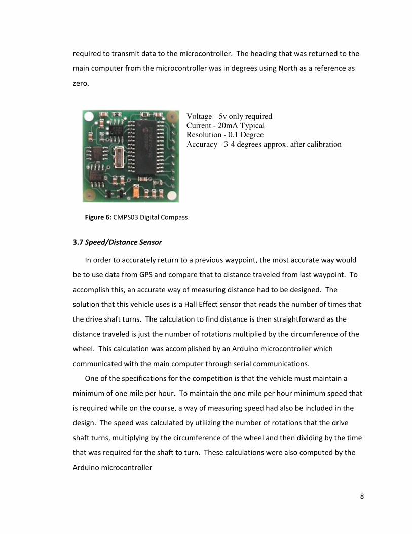
3.6 Digital Compass
GPS will give a heading of movement if the vehicle that it is attached to is moving.
This means that if the vehicle stops and turns, the vehicle will not know which direction
it is pointing until forward motion is again achieved. Therefore, the need for a digital
compass was needed so that the vehicles computer would know the direction of the
vehicle at all times. The compass that was used was a CMPS03; this digital compass
uses two magnetic field sensors that are perpendicular to each other which allow the
compass to measure the earth’s magnetic field in all orientations. By wiring the digital
compass to an Arduino microcontroller using I2C specifications only two wires were
8
required to transmit data to the microcontroller. The heading that was returned to the
main computer from the microcontroller was in degrees using North as a reference as
zero.
Voltage - 5v only required
Current - 20mA Typical
Resolution - 0.1 Degree
Accuracy - 3-4 degrees approx. after calibration
Figure 6: CMPS03 Digital Compass.
3.7 Speed/Distance Sensor
In order to accurately return to a previous waypoint, the most accurate way would
be to use data from GPS and compare that to distance traveled from last waypoint. To
accomplish this, an accurate way of measuring distance had to be designed. The
solution that this vehicle uses is a Hall Effect sensor that reads the number of times that
the drive shaft turns. The calculation to find distance is then straightforward as the
distance traveled is just the number of rotations multiplied by the circumference of the
wheel. This calculation was accomplished by an Arduino microcontroller which
communicated with the main computer through serial communications.
One of the specifications for the competition is that the vehicle must maintain a
minimum of one mile per hour. To maintain the one mile per hour minimum speed that
is required while on the course, a way of measuring speed had also be included in the
design. The speed was calculated by utilizing the number of rotations that the drive
shaft turns, multiplying by the circumference of the wheel and then dividing by the time
that was required for the shaft to turn. These calculations were also computed by the
Arduino microcontroller
9
3.8 Camera
For KITT’s main source of vision the Microsoft Kinect was uses as both a camera and
an infrared depth sensor. The Kinect camera generates a 640x480 color image from its
standard RGB camera, as well as a 640x480 image that contains depth data of the
objects in its field of view. These images were obtained through the use of the
OpenKinect Library, and they are used in the software to obtain data about obstacles on
KITT’s pathway.
Field of View
Horizontal field of view: 57 degrees
Vertical field of view: 43 degrees
Physical tilt range: ± 27 degrees
Depth sensor range: 1.2m - 3.5m
Data Streams
320x240 16-bit depth
640x480 32-bit colour
Figure 7: Xbox Connect.
A depth image is created from the Kinect using a process known grid distortion. Grid
distortion works essentially in three steps. First a grid of infrared light is emitted works
essentially in three steps. First a grid of infrared light is emitted from the Kinect. This
grid is then reflected back towards the sensor, with lines either being elongated or
condensed based on the distance away from the Kinect. The Kinect then processes this
grid to calculate the forward distance from the Kinect to the object.
For the actual processing of the image the first process is obtaining a edge map of
the obstacles. Using OpenCV, a digital image processing library, the color image is first
converted to a grayscale image. This image is then sent through a canny edge filter to
obtain edges of all the obstacles in the field of view. The canny edge filter works by
essentially comparing pixel values to nearest neighbor pixel values. If the two values are
shown to have difference of greater than a pre-selected threshold, that pixel is selected
as an edge.
Once a new image is obtained containing all obstacle values, it is cross referenced
with the depth image. From this, depth values for every obstacle can be obtained and a
10
map of both obstacles and distance from KITT can be obtained. Using these values, a 2D
map is created that contains all obstacles found from the Kinect, in reference to KITT.
This 2D map is then combined with data from other sensors to form essentially a top-
down view of around KITT, containing both past data and new data from the Kinect.
3.9 Safety Light
New requirements for the competition this year specified that each vehicle must
have a safety light. This light must remain illuminated when power is applied to the
vehicle and flash when the vehicle goes autonomous. This requirement was met
through the use of relays. By wiring the light to the common side of the relay, applying
12 volts to the normally closed side of the relay, and an automotive flashing relay to the
normally open side of the relay the light would remain illuminated as soon as the 12
volts supply was turned on. The ground of the coil side of the relay was wired to the
Dayton power relay. Therefore when the emergency stop circuit was closed, the coil for
the safety light relay was energized and the normally open contact of the relay was
closed making a continuous circuit making the light flash.
3.10 Algorithm
KITT utilizes a very common algorithm for path finding and obstacle avoidance,
which is known as the Vector Field Histogram (VFH). VFH works exceptionally well for
agile robots because its input is a 2D grid map containing object location as well as
target points, which is exactly how KITT’s sensor integration works. VFH contains 3
major steps in order to produce a final heading for the robot. They are as follows:
1. Generate map of obstacles and goal node
2. Using 2D map, create polar 1D polar histogram
3. Calculate heading and velocity
Most of the 2D map is already created from KITT’s sensors. A goal node just needs
to be added to the map, this being the next destination that KITT desires to reach, which
is entered as a GPS coordinate and translated to coordinates on the map. Once this is
added into the map a 1D polar histogram is created.
11
The polar histogram is created by calculating the sum, MΘ, of all the certainty
obstacle values that are located along some angle Θ. Θ is between 0 and 180 degrees,
and is measured from the current heading of KITT. Once the polar histogram is created,
all angles that are found to contain a value of MΘ under some pre-determined value,
which was chosen through experimentation, are selected. This is done to essentially find
a path that is almost guaranteed to be unobstructed by obstacles. The angle from this
set that is nearest to goal angle is selected as KITT’s new heading.
4. Emergency Stop
4.1 Purpose
For the vehicle to meet competition specifications and to operate in a safe manner,
an emergency stop circuit had to be implemented. The rules for the competition
specified that both a wireless and mechanical emergency stop was included in the
design. The wireless part of the stop circuit had to be effective for a minimum distance
of 100 feet, and the mechanical emergency stop switch had to be at the back of the
vehicle located between 2 and 4 feet tall. In the interest of being safe, a decision was
made so that if the vehicle were to exceed the maximum distance of the wireless stop
circuit, the vehicle would automatically stop. This made the vehicle safe in the three
imaginable cases that the vehicle would need to be stopped: The vehicle becomes
unstable and needs to be stopped wirelessly, the operator becomes incapacitated and
cannot stop the vehicle when needed, and the battery voltage of the transmitter falls
below the minimum operating voltage. In all three of these cases, the vehicle would go
to its maximum transmittable distance and stop.
4.2 Transmitter/Receiver Circuit
The transmitter that was used was a TWS 434A chip that broadcasts an AM
modulated signal at 433.92 Megahertz. Although this transmitter has an operating
voltage range of 2 to 12 volts, the HT12E encoder that was used has an operating
voltage range of 2 to 5.5 volts. Since the transmitter was to be powered by batteries,
12
the easiest way to stay in the range of both of these voltage ranges was to use three AA
batteries rated at 1.5 volts making the operating voltage of the transmitter 4.5 volts.
Figure 8: Transmitter Circuit.
The receiver that was used for this vehicle was a RWS 434 which has an operating
voltage range of 4.5 to 5.5 volts and receives an AM modulated signal at 433.92
Megahertz and the HT12D decoder was used has an operating range of 4.5 to 5.5 volts.
By using a 7805 +5V voltage regulator, voltage was able to be drawn from the vehicle’s
12 volt battery and converted to 5 volts for the circuit.
4.3 Relays
Since the wireless receiver is only rated for 4.5 milliamps, and the motor
controller could draw up to 80 amps, a circuit was designed to allow for these ratings.
When both kill switches are in the closed position, 12 volts is applied to a Dayton 100A
power relay. When this relay closes, the ground wires from the Roboteq are connected
to chassis ground and therefore allowing the Roboteq to control the steering and drive