CSM_S82K_DS_E_3_1 1 Switch Mode Power Supply S82K (3/7.5/15/30/50/90/100-W Models) Ultimate DIN-rail-mounting Power Supply with a Power Range of 3 to 100 W • EMI: EN 61204-3 class B • Input: 85 to 264 VAC (except 90-W and 100-W models) • Safety standards: UL 60950-1/508, cUL: CSA C22.2 No. 14 (Class 2: Per No. 223), cUR: CSA No. 60950-1, EN50178 (= VDE 0160) • Undervoltage alarm indication available for standard models.] • RoHS-compliant ! Refer to Safety Precautions for All Power Supplies. Model Number Structure ■ Model Number Legend Ordering Information ■ List of Models Note: For details on normal stock models, contact your nearest OMRON representative. Note:1. The output capacity of the S82K-03005 is 25 W. 2. The output current for S82K-P10024 during parallel operation is 3.78 A. 1. Power Factor Correction None: No P: Yes 3. Output Voltage 05: +5 VDC 12: +12 VDC 15: +15 VDC 24: +24 VDC 27: ±12 VDC 28: ±15 VDC 2. Power Ratings 003: 3 W 007: 7.5 W 015: 15 W 030: 30 W 050: 50 W 090: 90 W 100: 100 W S82K - 1 2 3 Note: Not all combinations are possible. Refer to List of Models in Ordering Information, below. Power ratings Output voltage Output current Function Configuration Models Output Undervoltage alarm indicator/output PFC 3 W 5 V 0.6 A Single output Yes No S82K-00305 12 V 0.25 A S82K-00312 15 V 0.2 A S82K-00315 24 V 0.13 A S82K-00324 7.5 W 5 V 1.5 A S82K-00705 12 V 0.6 A S82K-00712 15 V 0.5 A S82K-00715 24 V 0.3 A S82K-00724 ±12 V 0.3 A/0.2 A Dual output S82K-00727 ±15 V 0.2 A/0.2 A S82K-00728 15 W 5 V 2.5 A Single output S82K-01505 12 V 1.2 A S82K-01512 24 V 0.6 A S82K-01524 30 W 5 V 5.0 A S82K-03005 (See note 1.) 12 V 2.5 A S82K-03012 24 V 1.3 A S82K-03024 50 W 24 V 2.1 A S82K-05024 90 W 24 V 3.75 A No S82K-09024 Yes S82K-P09024 100 W 24 V 4.2 A (See note 2.) No S82K-10024 Yes S82K-P10024
Transcript
CSM_S82K_DS_E_3_1
1
Switch Mode Power Supply
S82K (3/7.5/15/30/50/90/100-W Models)
Ultimate DIN-rail-mounting Power Supply with a Power Range of 3 to 100 W
• EMI: EN 61204-3 class B
• Input: 85 to 264 VAC (except 90-W and 100-W models)
• Undervoltage alarm indication available for standard models.]• RoHS-compliant
! Refer to Safety Precautions for All Power Supplies.
Model Number Structure
Model Number Legend
Ordering Information
List of ModelsNote: For details on normal stock models, contact your nearest OMRON representative.
Note:1. The output capacity of the S82K-03005 is 25 W.2. The output current for S82K-P10024 during parallel operation is 3.78 A.
1. Power Factor CorrectionNone: NoP: Yes
3. Output Voltage05: +5 VDC12: +12 VDC15: +15 VDC
24: +24 VDC27: ±12 VDC28: ±15 VDC
2. Power Ratings003: 3 W007: 7.5 W015: 15 W030: 30 W
050: 50 W090: 90 W100: 100 W
S82K -1 2 3
Note: Not all combinations are possible. Refer to List of Models in Ordering Information, below.
Power ratings Output voltage Output current Function Configuration ModelsOutput Undervoltage alarm indicator/output PFC
3 W 5 V 0.6 A Single output Yes No S82K-0030512 V 0.25 A S82K-0031215 V 0.2 A S82K-0031524 V 0.13 A S82K-00324
7.5 W 5 V 1.5 A S82K-0070512 V 0.6 A S82K-0071215 V 0.5 A S82K-0071524 V 0.3 A S82K-00724±12 V 0.3 A/0.2 A Dual output S82K-00727±15 V 0.2 A/0.2 A S82K-00728
15 W 5 V 2.5 A Single output S82K-0150512 V 1.2 A S82K-0151224 V 0.6 A S82K-01524
30 W 5 V 5.0 A S82K-03005 (See note 1.)12 V 2.5 A S82K-0301224 V 1.3 A S82K-03024
50 W 24 V 2.1 A S82K-0502490 W 24 V 3.75 A No S82K-09024
Yes S82K-P09024100 W 24 V 4.2 A (See note 2.) No S82K-10024
Yes S82K-P10024
S82K
2
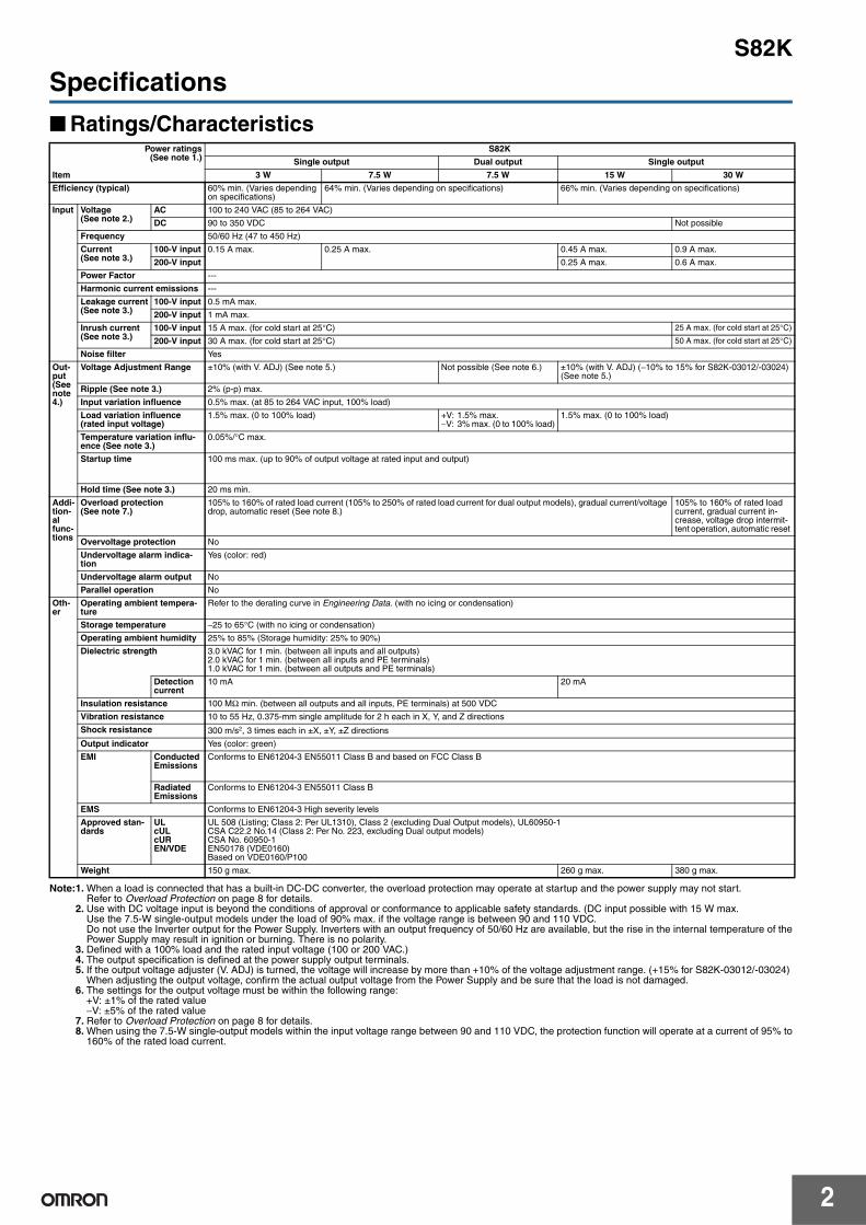
Specifications
Ratings/Characteristics
Note:1. When a load is connected that has a built-in DC-DC converter, the overload protection may operate at startup and the power supply may not start. Refer to Overload Protection on page 8 for details.
2. Use with DC voltage input is beyond the conditions of approval or conformance to applicable safety standards. (DC input possible with 15 W max.Use the 7.5-W single-output models under the load of 90% max. if the voltage range is between 90 and 110 VDC.Do not use the Inverter output for the Power Supply. Inverters with an output frequency of 50/60 Hz are available, but the rise in the internal temperature of thePower Supply may result in ignition or burning. There is no polarity.
3. Defined with a 100% load and the rated input voltage (100 or 200 VAC.)4. The output specification is defined at the power supply output terminals.5. If the output voltage adjuster (V. ADJ) is turned, the voltage will increase by more than +10% of the voltage adjustment range. (+15% for S82K-03012/-03024)
When adjusting the output voltage, confirm the actual output voltage from the Power Supply and be sure that the load is not damaged.6. The settings for the output voltage must be within the following range:
+V: ±1% of the rated value−V: ±5% of the rated value
7. Refer to Overload Protection on page 8 for details.8. When using the 7.5-W single-output models within the input voltage range between 90 and 110 VDC, the protection function will operate at a current of 95% to
160% of the rated load current.
Power ratings (See note 1.)
S82K
Single output Dual output Single output
Item 3 W 7.5 W 7.5 W 15 W 30 W
Efficiency (typical) 60% min. (Varies depending on specifications)
64% min. (Varies depending on specifications) 66% min. (Varies depending on specifications)
Input Voltage (See note 2.)
AC 100 to 240 VAC (85 to 264 VAC)
DC 90 to 350 VDC Not possible
Frequency 50/60 Hz (47 to 450 Hz)
Current (See note 3.)
100-V input 0.15 A max. 0.25 A max. 0.45 A max. 0.9 A max.
200-V input 0.25 A max. 0.6 A max.
Power Factor ---
Harmonic current emissions ---
Leakage current(See note 3.)
100-V input 0.5 mA max.
200-V input 1 mA max.
Inrush current (See note 3.)
100-V input 15 A max. (for cold start at 25°C) 25 A max. (for cold start at 25°C)
200-V input 30 A max. (for cold start at 25°C) 50 A max. (for cold start at 25°C)
Noise filter Yes
Out-put (See note 4.)
Voltage Adjustment Range ±10% (with V. ADJ) (See note 5.) Not possible (See note 6.) ±10% (with V. ADJ) (−10% to 15% for S82K-03012/-03024) (See note 5.)
1.5% max. (0 to 100% load) +V: 1.5% max.−V: 3% max. (0 to 100% load)
1.5% max. (0 to 100% load)
Temperature variation influ-ence (See note 3.)
0.05%/°C max.
Startup time 100 ms max. (up to 90% of output voltage at rated input and output)
Hold time (See note 3.) 20 ms min.
Addi-tion-al func-tions
Overload protection (See note 7.)
105% to 160% of rated load current (105% to 250% of rated load current for dual output models), gradual current/voltage drop, automatic reset (See note 8.)
105% to 160% of rated load current, gradual current in-crease, voltage drop intermit-tent operation, automatic reset
Overvoltage protection No
Undervoltage alarm indica-tion
Yes (color: red)
Undervoltage alarm output No
Parallel operation No
Oth-er
Operating ambient tempera-ture
Refer to the derating curve in Engineering Data. (with no icing or condensation)
Storage temperature −25 to 65°C (with no icing or condensation)
Operating ambient humidity 25% to 85% (Storage humidity: 25% to 90%)
Dielectric strength 3.0 kVAC for 1 min. (between all inputs and all outputs)2.0 kVAC for 1 min. (between all inputs and PE terminals)1.0 kVAC for 1 min. (between all outputs and PE terminals)
Detection current
10 mA 20 mA
Insulation resistance 100 MΩ min. (between all outputs and all inputs, PE terminals) at 500 VDC
Vibration resistance 10 to 55 Hz, 0.375-mm single amplitude for 2 h each in X, Y, and Z directions
Shock resistance 300 m/s2, 3 times each in ±X, ±Y, ±Z directions
Output indicator Yes (color: green)
EMI Conducted Emissions
Conforms to EN61204-3 EN55011 Class B and based on FCC Class B
RadiatedEmissions
Conforms to EN61204-3 EN55011 Class B
EMS Conforms to EN61204-3 High severity levels
Approved stan-dards
ULcULcUREN/VDE
UL 508 (Listing; Class 2: Per UL1310), Class 2 (excluding Dual Output models), UL60950-1CSA C22.2 No.14 (Class 2: Per No. 223, excluding Dual output models)CSA No. 60950-1EN50178 (VDE0160)Based on VDE0160/P100
Weight 150 g max. 260 g max. 380 g max.
S82K
3
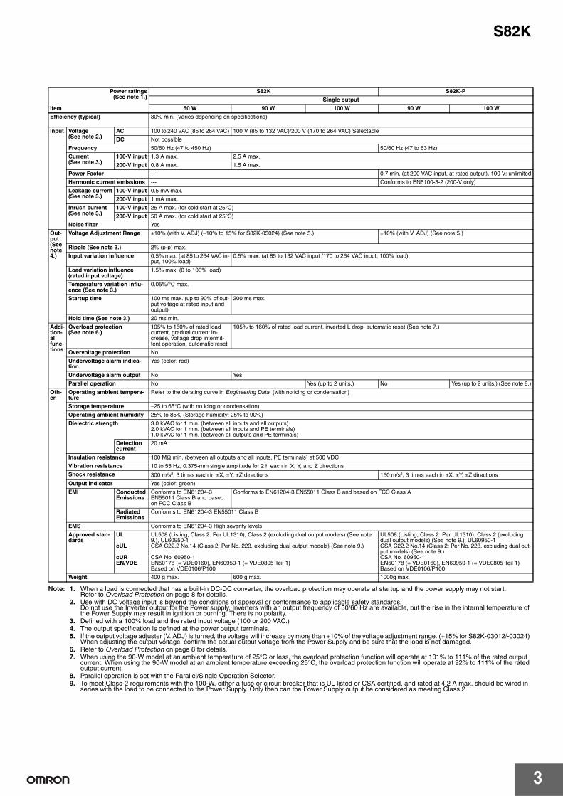
Note: 1. When a load is connected that has a built-in DC-DC converter, the overload protection may operate at startup and the power supply may not start. Refer to Overload Protection on page 8 for details.
2. Use with DC voltage input is beyond the conditions of approval or conformance to applicable safety standards.Do not use the Inverter output for the Power supply. Inverters with an output frequency of 50/60 Hz are available, but the rise in the internal temperature of the Power Supply may result in ignition or burning. There is no polarity.
3. Defined with a 100% load and the rated input voltage (100 or 200 VAC.)4. The output specification is defined at the power output terminals.5. If the output voltage adjuster (V. ADJ) is turned, the voltage will increase by more than +10% of the voltage adjustment range. (+15% for S82K-03012/-03024)
When adjusting the output voltage, confirm the actual output voltage from the Power Supply and be sure that the load is not damaged.6. Refer to Overload Protection on page 8 for details.7. When using the 90-W model at an ambient temperature of 25°C or less, the overload protection function will operate at 101% to 111% of the rated output
current. When using the 90-W model at an ambient temperature exceeding 25°C, the overload protection function will operate at 92% to 111% of the rated output current.
8. Parallel operation is set with the Parallel/Single Operation Selector.9. To meet Class-2 requirements with the 100-W, either a fuse or circuit breaker that is UL listed or CSA certified, and rated at 4.2 A max. should be wired in
series with the load to be connected to the Power Supply. Only then can the Power Supply output be considered as meeting Class 2.
Power ratings (See note 1.)
S82K S82K-P
Single output
Item 50 W 90 W 100 W 90 W 100 W
Efficiency (typical) 80% min. (Varies depending on specifications)
Input Voltage (See note 2.)
AC 100 to 240 VAC (85 to 264 VAC) 100 V (85 to 132 VAC)/200 V (170 to 264 VAC) Selectable
DC Not possible
Frequency 50/60 Hz (47 to 450 Hz) 50/60 Hz (47 to 63 Hz)
Current (See note 3.)
100-V input 1.3 A max. 2.5 A max.
200-V input 0.8 A max. 1.5 A max.
Power Factor --- 0.7 min. (at 200 VAC input, at rated output), 100 V: unlimited
Harmonic current emissions --- Conforms to EN6100-3-2 (200-V only)
Leakage current(See note 3.)
100-V input 0.5 mA max.
200-V input 1 mA max.
Inrush current (See note 3.)
100-V input 25 A max. (for cold start at 25°C)
200-V input 50 A max. (for cold start at 25°C)
Noise filter Yes
Out-put (See note 4.)
Voltage Adjustment Range ±10% (with V. ADJ) (−10% to 15% for S82K-05024) (See note 5.) ±10% (with V. ADJ) (See note 5.)
0.5% max. (at 85 to 132 VAC input /170 to 264 VAC input, 100% load)
Load variation influence (rated input voltage)
1.5% max. (0 to 100% load)
Temperature variation influ-ence (See note 3.)
0.05%/°C max.
Startup time 100 ms max. (up to 90% of out-put voltage at rated input and output)
200 ms max.
Hold time (See note 3.) 20 ms min.
Addi-tion-al func-tions
Overload protection (See note 6.)
105% to 160% of rated load current, gradual current in-crease, voltage drop intermit-tent operation, automatic reset
105% to 160% of rated load current, inverted L drop, automatic reset (See note 7.)
Overvoltage protection No
Undervoltage alarm indica-tion
Yes (color: red)
Undervoltage alarm output No Yes
Parallel operation No Yes (up to 2 units.) No Yes (up to 2 units.) (See note 8.)
Oth-er
Operating ambient tempera-ture
Refer to the derating curve in Engineering Data. (with no icing or condensation)
Storage temperature −25 to 65°C (with no icing or condensation)
Operating ambient humidity 25% to 85% (Storage humidity: 25% to 90%)
Dielectric strength 3.0 kVAC for 1 min. (between all inputs and all outputs)2.0 kVAC for 1 min. (between all inputs and PE terminals)1.0 kVAC for 1 min. (between all outputs and PE terminals)
Detection current
20 mA
Insulation resistance 100 MΩ min. (between all outputs and all inputs, PE terminals) at 500 VDC
Vibration resistance 10 to 55 Hz, 0.375-mm single amplitude for 2 h each in X, Y, and Z directions
Shock resistance 300 m/s2, 3 times each in ±X, ±Y, ±Z directions 150 m/s2, 3 times each in ±X, ±Y, ±Z directions
Output indicator Yes (color: green)
EMI Conducted Emissions
Conforms to EN61204-3 EN55011 Class B and based on FCC Class B
Conforms to EN61204-3 EN55011 Class B and based on FCC Class A
RadiatedEmissions
Conforms to EN61204-3 EN55011 Class B
EMS Conforms to EN61204-3 High severity levels
Approved stan-dards
UL
cUL
cUREN/VDE
UL508 (Listing; Class 2: Per UL1310), Class 2 (excluding dual output models) (See note 9.), UL60950-1CSA C22.2 No.14 (Class 2: Per No. 223, excluding dual output models) (See note 9.)
CSA No. 60950-1EN50178 (= VDE0160), EN60950-1 (= VDE0805 Teil 1)Based on VDE0106/P100
UL508 (Listing; Class 2: Per UL1310), Class 2 (excluding dual output models) (See note 9.), UL60950-1CSA C22.2 No.14 (Class 2: Per No. 223, excluding dual out-put models) (See note 9.)CSA No. 60950-1EN50178 (= VDE0160), EN60950-1 (= VDE0805 Teil 1)Based on VDE0106/P100
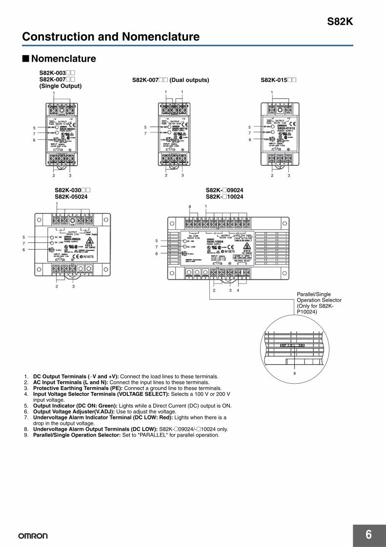
Parallel/Single Operation Selector (Only for S82K-P10024)
1. DC Output Terminals (−V and +V): Connect the load lines to these terminals.2. AC Input Terminals (L and N): Connect the input lines to these terminals.3. Protective Earthing Terminals (PE): Connect a ground line to these terminals.4. Input Voltage Selector Terminals (VOLTAGE SELECT): Selects a 100 V or 200 V
input voltage.5. Output Indicator (DC ON: Green): Lights while a Direct Current (DC) output is ON.6. Output Voltage Adjuster(V.ADJ): Use to adjust the voltage.7. Undervoltage Alarm Indicator Terminal (DC LOW: Red): Lights when there is a
drop in the output voltage.8. Undervoltage Alarm Output Terminals (DC LOW): S82K-@09024/-@10024 only.9. Parallel/Single Operation Selector: Set to "PARALLEL" for parallel operation.
S82K
7
Engineering Data
Derating Curve (A: Standard mounting, B: Face-up mounting)
Mounting
65 65
90
Load
(%
)
Ambient temperature (°C)
3-/7.5-/15-/30-/50-/100-W Models
Load
(%
)
Ambient temperature (°C)
Load
(%
)
Ambient temperature (°C)
Installation A Installation A
Installation B
100-W Models with PFC(S82K-P10024)
Installation B
Parallel Operation
100-W Models without PFC(S82K-10024)
Installation A
Installation B
Single-Unit Operation Parallel Operation
S82K-P10024: 85-VAC input
S82K-03005 Installation A
Note: When using the 7.5-W single-output models within the input voltage range between 90 and 110 VDC, the load rate will become 90% or less.
S82K-P10024: 85-VAC input
65
90-W Models
Load
(%
)
Ambient temperature (°C)
Installation A
Installation B
Single-Unit Operation
S82K-P09024: 85-VAC input
Note: 1. The derating curve may vary depending on the installation conditions.2. Multiple units cannot be installed in a configuration where they are lined up vertically.3. Use the 7.5-W single-output models under the load of 90% max. if the voltage range is between 90 and 110 VDC.4. The cold-start time will be longer when using S82K-P09024 or S82K-P10024 with an 85-VAC input.
(A) Standard mounting (B) Face-up mounting
Top Top
Note: Installations other than (A) and (B) are not possible.
S82K
8
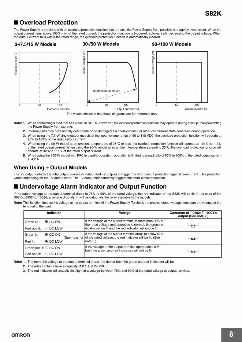
Overload ProtectionThe Power Supply is provided with an overload protection function that protects the Power Supply from possible damage by overcurrent. When theoutput current rises above 105% min. of the rated current, the protection function is triggered, automatically decreasing the output voltage. Whenthe output current falls within the rated range, the overload protection function is automatically cleared.
Note: 1. When connecting a load that has a built-in DC-DC converter, the overload protection function may operate during startup, thus preventingthe Power Supply from starting.
2. Internal parts may occasionally deteriorate or be damaged if a short-circuited or other overcurrent state continues during operation.3. When using the 7.5-W single-output models at the input voltage range of 90 to 110 VDC, the overload protection function will operate at
95% to 160% of the rated output current.4. When using the 90-W model at an ambient temperature of 25°C or less, the overload protection function will operate at 101% to 111%
of the rated output current. When using the 90-W model at an ambient temperature exceeding 25°C, the overload protection function willoperate at 92% to 111% of the rated output current.
5. When using the 100-W model with PFC in parallel operation, operation is limited to a load ratio of 90% to 100% of the rated output currentat 4.2 A.
When Using ± Output ModelsThe +V output detects the total output power (+V output and −V output) to trigger the short-circuit protection against overcurrent. This protectionvaries depending on the −V output state. The −V output independently triggers the short-circuit protection.
Undervoltage Alarm Indicator and Output Function If the output voltage at the output terminal drops to 75% to 90% of the rated voltage, the red indicator of the S82K will be lit. In the case of theS82K-@09024/@10024, a voltage drop alarm will be output via the relay available in the models.
Note: This function detects the voltage at the output terminal of the Power Supply. To check the precise output voltage, measure the voltage at theterminal of the load.
Note: 1. The more the voltage at the output terminal drops, the darker both the green and red indicators will be.2. The relay contacts have a capacity of 0.1 A at 24 VDC.3. The red indicator will actually first light at a voltage between 75% and 90% of the rated voltage at output terminal.
Output current (%)0 10050
Out
put v
olta
ge (
V)
50
Intermittent operation
0 100
Output current (%)
Out
put v
olta
ge (
V)
3-/7.5/15 W Models 30-/50 W Models
0 10050
Output current (%)
Out
put v
olta
ge (
V)
90-/100 W Models
The values shown in the above diagrams are for reference only.
Indicator Voltage Operation of @09024/@10024’s output (See note 2.)
If the voltage at the output terminal is more than 82% of the rated voltage and operation is normal, the green in-dicator will be lit and the red indicator will not be lit.
If the voltage at the output terminal drops to below 82% of the rated voltage, the red indicator will be lit. (See note 3.)
If the voltage at the output terminal approaches 0 V, both the green and red indicators will not be lit.
Green lit: DC ON
Red not lit: DC LOW
Green lit: DC ON
Red lit: DC LOW(See note 1.)
Green not lit: DC ON
Red not lit: DC LOW
S82K
9
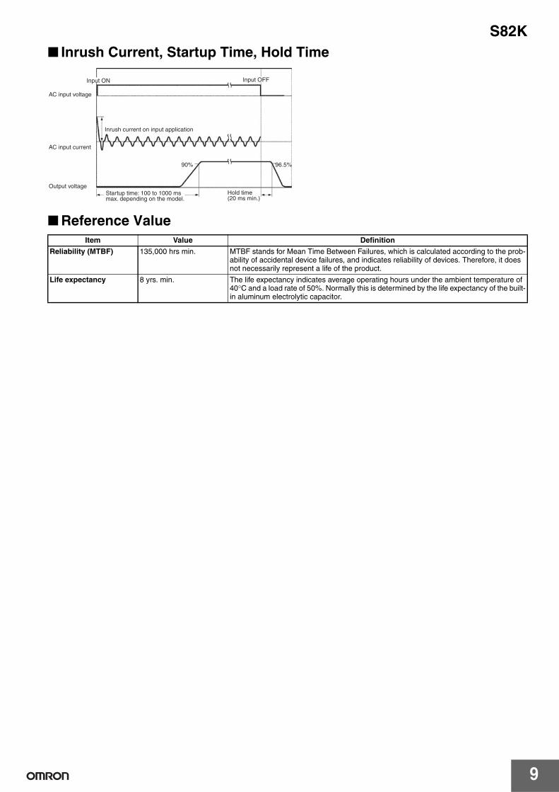
Inrush Current, Startup Time, Hold Time
Reference Value
90% 96.5%
Input ON
AC input voltage
AC input current
Output voltage
Inrush current on input application
Input OFF
Startup time: 100 to 1000 ms max. depending on the model.
Hold time (20 ms min.)
Item Value Definition
Reliability (MTBF) 135,000 hrs min. MTBF stands for Mean Time Between Failures, which is calculated according to the prob-ability of accidental device failures, and indicates reliability of devices. Therefore, it does not necessarily represent a life of the product.
Life expectancy 8 yrs. min. The life expectancy indicates average operating hours under the ambient temperature of 40°C and a load rate of 50%. Normally this is determined by the life expectancy of the built-in aluminum electrolytic capacitor.
S82K
10
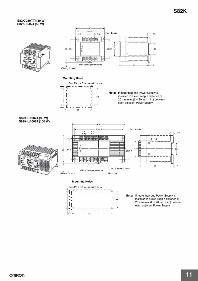
DimensionsNote: All units are in millimeters unless otherwise indicated.
35±0.15 25±0.15
37.5±0.1
27±0.1
M3.5 with square washer
Two, 4.5±0.1 dia.
S82K-003@@ (3 W) S82K-007@@ (7.5 W)
(Sliding: 7 max.)
Note: If more than one Power Supply is installed in a row, keep a distance of 20 mm min. (L = 20 mm min.) between each adjacent Power Supply.
Mounting Brackets (Supplied)Used when not mounting the Power Supply directly on the DIN rail.
Mounting HolesAttached Mounting Bracket
M4 or 4.5-dia. hole
75 58.1
459.8 8.3
45
91 5
35
7.5
S82K-015@@ (15 W)
60
L 35
Mounting Holes
Two, M4 or 4.5-dia. mounting holes
4.6(Sliding: 7 max.) M3.5 with square
washer
Note: If more than one Power Supply is installed in a row, keep a distance of 20 mm min. (L = 20 mm min.) between each adjacent Power Supply.
S82K
11
4
60
80L
35
(Sliding: 7 max.)
M3.5 with square washer
Four, M4 or 4.5-dia. mounting holes
Four, 4.5 dia.
Mounting Holes
S82K-030@@ (30 W)S82K-05024 (50 W)
Note: If more than one Power Supply is installed in a row, keep a distance of 20 mm min. (L = 20 mm min.) between each adjacent Power Supply.
60
135L
58.175
4
60±0.2
145
135±0.2
91
35
7.5
5
45
8.39.8
Four, M4 or 4.5-dia. mounting holes
(Sliding: 7 max.)
M3.5 with square washerShort bar
M3.5 terminal screw
Four, 4.5 dia.
Mounting Holes
S82K-@09024 (90 W) S82K-@10024 (100 W)
Note: If more than one Power Supply is installed in a row, keep a distance of 20 mm min. (L = 20 mm min.) between each adjacent Power Supply.
S82K
12
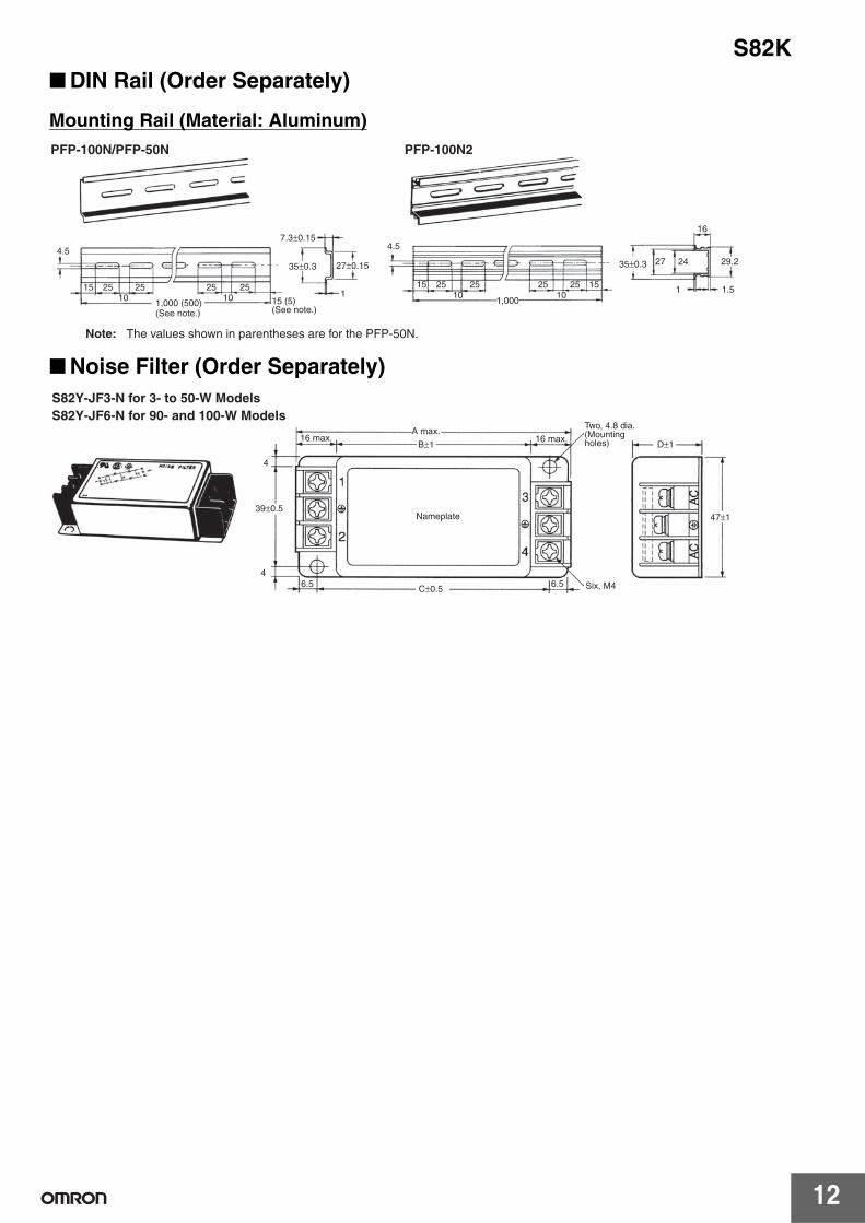
DIN Rail (Order Separately)
Mounting Rail (Material: Aluminum)
Noise Filter (Order Separately)
4.5
15 25 25 25 2510 101,000 (500)
7.3±0.15
35±0.3 27±0.15
115 (5)
4.5
15 25 25 25 25 1510 10
1,000
35±0.3 27 24
16
29.2
1 1.5
(See note.) (See note.)
PFP-100N2PFP-100N/PFP-50N
Note: The values shown in parentheses are for the PFP-50N.
39±0.5
B±1 D±1
6.54
6.5C±0.5
4
47±1
16 max.A max.
Six, M4
16 max.
Nameplate
Two, 4.8 dia. (Mounting holes)
S82Y-JF3-N for 3- to 50-W Models S82Y-JF6-N for 90- and 100-W Models
S82K
13
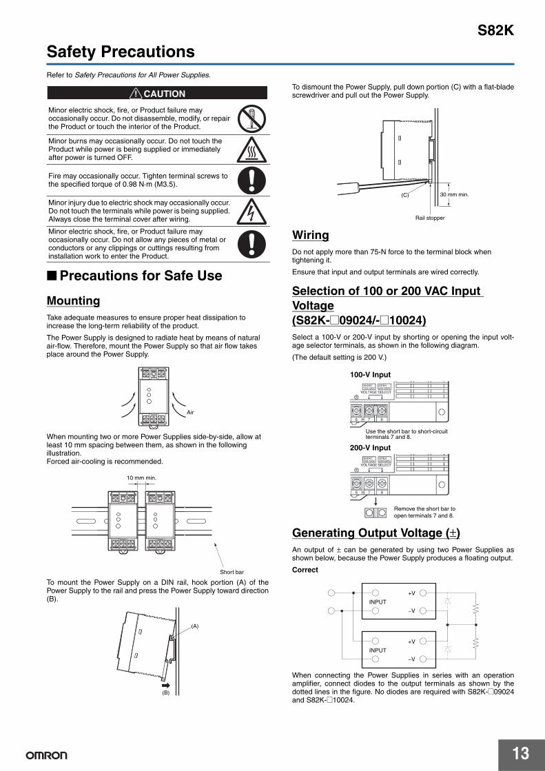
Safety PrecautionsRefer to Safety Precautions for All Power Supplies.
!CAUTION
Precautions for Safe Use
MountingTake adequate measures to ensure proper heat dissipation to increase the long-term reliability of the product.
The Power Supply is designed to radiate heat by means of natural air-flow. Therefore, mount the Power Supply so that air flow takes place around the Power Supply.
When mounting two or more Power Supplies side-by-side, allow at least 10 mm spacing between them, as shown in the following illustration.Forced air-cooling is recommended.
To mount the Power Supply on a DIN rail, hook portion (A) of thePower Supply to the rail and press the Power Supply toward direction(B).
To dismount the Power Supply, pull down portion (C) with a flat-bladescrewdriver and pull out the Power Supply.
WiringDo not apply more than 75-N force to the terminal block when tightening it.
Ensure that input and output terminals are wired correctly.
Selection of 100 or 200 VAC Input Voltage(S82K-@09024/-@10024)Select a 100-V or 200-V input by shorting or opening the input volt-age selector terminals, as shown in the following diagram.
(The default setting is 200 V.)
Generating Output Voltage (±)An output of ± can be generated by using two Power Supplies asshown below, because the Power Supply produces a floating output.
Correct
When connecting the Power Supplies in series with an operationamplifier, connect diodes to the output terminals as shown by thedotted lines in the figure. No diodes are required with S82K-@09024and S82K-@10024.
Minor electric shock, fire, or Product failure may occasionally occur. Do not disassemble, modify, or repair the Product or touch the interior of the Product.
Minor burns may occasionally occur. Do not touch the Product while power is being supplied or immediately after power is turned OFF.
Fire may occasionally occur. Tighten terminal screws to the specified torque of 0.98 N·m (M3.5).
Minor injury due to electric shock may occasionally occur. Do not touch the terminals while power is being supplied. Always close the terminal cover after wiring.
Minor electric shock, fire, or Product failure may occasionally occur. Do not allow any pieces of metal or conductors or any clippings or cuttings resulting from installation work to enter the Product.
Air
10 mm min.
Short bar
(A)
(B)
Rail stopper
30 mm min.(C)
Remove the short bar toopen terminals 7 and 8.
Use the short bar to short-circuit terminals 7 and 8.
100-V Input
200-V Input
+V
−V
+V
−V
INPUT
INPUT
S82K
14
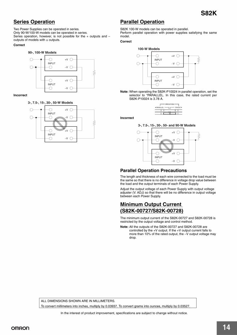
Series OperationTwo Power Supplies can be operated in series.Only 90-W/100-W models can be operated in series.Series operation, however, is not possible for the + outputs and –outputs of models with ± outputs.
Correct
Incorrect
Parallel OperationS82K 100-W models can be operated in parallel.Perform parallel operation with power supplies satisfying the samemodel.
Correct
Note: When operating the S82K-P10024 in parallel operation, set theselector to “PARALLEL. In this case, the rated current perS82K-P10024 is 3.78 A.
Incorrect
Parallel Operation PrecautionsThe length and thickness of each wire connected to the load must be the same so that there is no difference in voltage drop value between the load and the output terminals of each Power Supply.
Adjust the output voltage of each Power Supply with output voltage adjuster (V. ADJ) so that there will be no difference in output voltage between each Power Supply.
Minimum Output Current (S82K-00727/S82K-00728)The minimum output current of the S82K-00727 and S82K-00728 is restricted by the output voltage and control method.
Note: All the outputs of the S82K-00727 and S82K-00728 are controlled by the +V output. If the +V output current falls to more than 10% of the rated output, the –V output voltage may drop.
+V
−V
+V
−V
90-, 100-W Models
INPUT
INPUT
+V
−V
+V
−V
3-, 7.5-, 15-, 30-, 50-W Models
INPUT
INPUT
+V
−V
+V
−V
INPUT
INPUT
100-W Models
+V
−V
+V
−V
INPUT
INPUT
3-, 7.5-, 15-, 30-, 50- and 90-W Models
In the interest of product improvement, specifications are subject to change without notice.
ALL DIMENSIONS SHOWN ARE IN MILLIMETERS.
To convert millimeters into inches, multiply by 0.03937. To convert grams into ounces, multiply by 0.03527.
Read and Understand This Catalog Please read and understand this catalog before purchasing the products. Please consult your OMRON representative if you have any questions or comments.
Warranty and Limitations of Liability WARRANTY OMRON's exclusive warranty is that the products are free from defects in materials and workmanship for a period of one year (or other period if specified) from date of sale by OMRON. OMRON MAKES NO WARRANTY OR REPRESENTATION, EXPRESS OR IMPLIED, REGARDING NON-INFRINGEMENT, MERCHANTABILITY, OR FITNESS FOR PARTICULAR PURPOSE OF THE PRODUCTS. ANY BUYER OR USER ACKNOWLEDGES THAT THE BUYER OR USER ALONE HAS DETERMINED THAT THE PRODUCTS WILL SUITABLY MEET THE REQUIREMENTS OF THEIR INTENDED USE. OMRON DISCLAIMS ALL OTHER WARRANTIES, EXPRESS OR IMPLIED. LIMITATIONS OF LIABILITY OMRON SHALL NOT BE RESPONSIBLE FOR SPECIAL, INDIRECT, OR CONSEQUENTIAL DAMAGES, LOSS OF PROFITS OR COMMERCIAL LOSS IN ANY WAY CONNECTED WITH THE PRODUCTS, WHETHER SUCH CLAIM IS BASED ON CONTRACT, WARRANTY, NEGLIGENCE, OR STRICT LIABILITY. In no event shall the responsibility of OMRON for any act exceed the individual price of the product on which liability is asserted. IN NO EVENT SHALL OMRON BE RESPONSIBLE FOR WARRANTY, REPAIR, OR OTHER CLAIMS REGARDING THE PRODUCTS UNLESS OMRON'S ANALYSIS CONFIRMS THAT THE PRODUCTS WERE PROPERLY HANDLED, STORED, INSTALLED, AND MAINTAINED AND NOT SUBJECT TO CONTAMINATION, ABUSE, MISUSE, OR INAPPROPRIATE MODIFICATION OR REPAIR.
Application Considerations SUITABILITY FOR USE OMRON shall not be responsible for conformity with any standards, codes, or regulations that apply to the combination of products in the customer's application or use of the products. At the customer's request, OMRON will provide applicable third party certification documents identifying ratings and limitations of use that apply to the products. This information by itself is not sufficient for a complete determination of the suitability of the products in combination with the end product, machine, system, or other application or use. The following are some examples of applications for which particular attention must be given. This is not intended to be an exhaustive list of all possible uses of the products, nor is it intended to imply that the uses listed may be suitable for the products:
• Outdoor use, uses involving potential chemical contamination or electrical interference, or conditions or uses not described in this catalog. • Nuclear energy control systems, combustion systems, railroad systems, aviation systems, medical equipment, amusement machines, vehicles,
safety equipment, and installations subject to separate industry or government regulations. • Systems, machines, and equipment that could present a risk to life or property.
Please know and observe all prohibitions of use applicable to the products. NEVER USE THE PRODUCTS FOR AN APPLICATION INVOLVING SERIOUS RISK TO LIFE OR PROPERTY WITHOUT ENSURING THAT THE SYSTEM AS A WHOLE HAS BEEN DESIGNED TO ADDRESS THE RISKS, AND THAT THE OMRON PRODUCTS ARE PROPERLY RATED AND INSTALLED FOR THE INTENDED USE WITHIN THE OVERALL EQUIPMENT OR SYSTEM. PROGRAMMABLE PRODUCTS OMRON shall not be responsible for the user's programming of a programmable product, or any consequence thereof.
Disclaimers CHANGE IN SPECIFICATIONS Product specifications and accessories may be changed at any time based on improvements and other reasons. It is our practice to change model numbers when published ratings or features are changed, or when significant construction changes are made. However, some specifications of the products may be changed without any notice. When in doubt, special model numbers may be assigned to fix or establish key specifications for your application on your request. Please consult with your OMRON representative at any time to confirm actual specifications of purchased products. DIMENSIONS AND WEIGHTS Dimensions and weights are nominal and are not to be used for manufacturing purposes, even when tolerances are shown. PERFORMANCE DATA Performance data given in this catalog is provided as a guide for the user in determining suitability and does not constitute a warranty. It may represent the result of OMRON’s test conditions, and the users must correlate it to actual application requirements. Actual performance is subject to the OMRON Warranty and Limitations of Liability. ERRORS AND OMISSIONS The information in this document has been carefully checked and is believed to be accurate; however, no responsibility is assumed for clerical, typographical, or proofreading errors, or omissions.
2011.1
In the interest of product improvement, specifications are subject to change without notice.
OMRON Corporation Industrial Automation Company http://www.ia.omron.com/
(c)Copyright OMRON Corporation 2011 All Right Reserved.
Mouser Electronics
Authorized Distributor
Click to View Pricing, Inventory, Delivery & Lifecycle Information: Omron: