current output output Switching Power Supply S82K DIN-Rail Mount Power Supply with a Wide Power Range of 3 to 100 W � Universal input voltage range. � All models are UL 508 listed. � Class 2 approved on all models below 100 W, except dual-output types. � Undervoltage indicators on all models. 90-W and 100-W models have alarm and output indicators. � PFC models meet EN61000-3-2 (limits for harmonic current emissions). � Parallel operation capability (100 W). � Finger-safe terminal block with cover according to VDE0106/P100. � Approvals: UL, CSA, VDE, and CE. � 3-year warranty. Ordering Information � SWITCHING POWER SUPPLIES Stock Note: Shaded models are normally stocked. Rated input voltage Power ratings Output voltage Output Function configuration Part number voltage current Output Undervoltage alarm PFC 100 to 240 VAC 3 W 5 V 0.6 A Single output Indicator only No S82K-00305 12 V 0.25 A S82K-00312 15 V 0.2 A S82K-00315 24 V 0.13 A S82K-00324 7.5 W 5 V 1.5 A S82K-00705 12 V 0.6 A S82K-00712 15 V 0.5 A S82K-00715 24 V 0.3 A S82K-00724 +12 V/–12 V 0.3 A/0.2 A Dual output S82K-00727 +15 V/–15 V 0.2 A/0.2 A S82K-00728 15 W 5 V 2.5 A Single output S82K-01505 12 V 1.2 A S82K-01512 24 V 0.6 A S82K-01524 (This table continues on the next page.) Switching Power Supply S82K 1 Buy Now: www.ValinOnline.com | Phone: 800-774-5630 | Email: [email protected]
Transcript
currentPart number
output100 to 240 VAC 3 W No
7.5 W
output15 W
Switching Power Supply
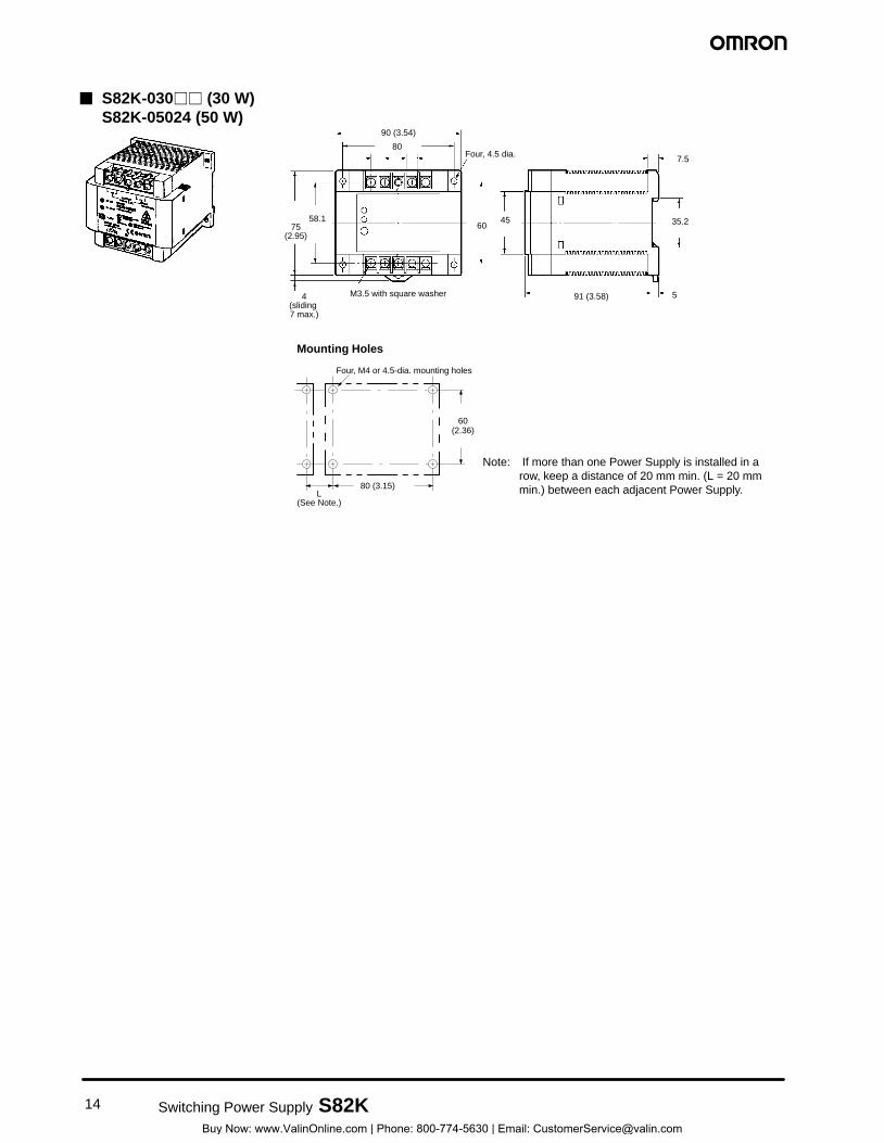
S82K DIN-Rail Mount Power Supply with a Wide Power Range of 3 to 100 W
Universal input voltage range.
All models are UL 508 listed.
Class 2 approved on all models below 100 W, except dual-output types.
Undervoltage indicators on all models. 90-W and 100-W models have alarm and output indicators.
PFC models meet EN61000-3-2 (limits for harmonic current emissions).
Parallel operation capability (100 W).
Finger-safe terminal block with cover according to VDE0106/P100.
Approvals: UL, CSA, VDE, and CE.
3-year warranty.
Ordering Information SWITCHING POWER SUPPLIES
Stock Note: Shaded models are normally stocked.
Rated inputRated input voltage
Power ratingsPower ratings Output voltageOutput voltage OutputOutput Function configuration Part number voltage current Output Undervoltage
alarm PFC
100 to 240 VAC 3 W 5 V 0.6 A SingleSingle output
Indicator onlyIndicator only No S82K-00305
12 V 0.25 A S82K-00312
15 V 0.2 A S82K-00315
24 V 0.13 A S82K-00324
7.5 W 5 V 1.5 A S82K-00705
12 V 0.6 A S82K-00712
15 V 0.5 A S82K-00715
24 V 0.3 A S82K-00724
+12 V/–12 V 0.3 A/0.2 A Dual outputDual output S82K-00727
Power rating 3 W 7.5 W 7.5 W 15 W 30 W 50 W 90 W 100 W
Efficiency (typical) 60% to 80% (Varies depending on specifications.)
Input
Voltage (See Note 1.)Note 1.)
AC 100 to 240 V (85 to 264 V) 120 V (85 to 132 V)/ 240 V (170 to 264 V) Selectable
DC 90 to 350 V (See Note 2.) Not possible
Frequency 50/60 Hz (47 to 450 Hz)
Current (See Note 3.) (See Note 3.)
100-V input
0.15 A max. 0.25 A max. 0.45 A max. 0.9 A max. 1.3 A max. 2.5 A max.
200-V input
0.25 A max. 0.6 A max. 0.8 A max. 1.5 A max.
Leakage current (See(See Note 3.)
100-V input
0.5 mA max.
200-V input
1 mA max.
Inrush current (See(See Note 3.)
100-V input
15 A max. 25 A max.
200-V input
30 A max. 50 A max.
Noise filter Yes
Output (See Note 4.)
Voltage adjustment range
±10% (V.ADJ) Not possible (See Note 5.)
±10% (V.ADJ); –10% to 15% for S82K-03012/-03024/-05024
Ripple (See Note 3.)
2% (p-p) max.
Input variation influence
0.5 % max. (at 85 to 264 VAC, 100% load) 0.5 % max. (at 85 to 132 VAC/ 170 to 264 VAC input, 100% load)
Load variation influence
1.5% max. (0 to 100% load)
+V: 1.5% max. -V: 3 % max. (0 to 100% load)
1.5% max. (0 to 100% load)
1.5% max. (10 to 100% load)
Temperature variation influence (See Note 3.)
0.05%/°C max.
Startup time 100 ms max. (up to 90% of output voltage at rated input and output) 200 ms max.
Hold time (See Note 3.)
20 ms min.
(This table continues on the next page.)
Note: 1. Use with DC voltage input is beyond the conditions of approval or conformance to applicable safety standards. 2. Use the 7.5-W single-output models under the load of 90% max. if the voltage range is between 90 and 110 VDC. 3. Defined with a 100% load and the rated input voltage (100 or 200 VAC). 4. The output specification is defined at the power supply output terminals. 5. The settings for the output voltage must be within the following range:
+V: ±1% of the rated value –V: ±5% of the rated value
Specifications Table – continued from previous page
Item Single output Dual outputs
Single output
Power rating 3 W 7.5 W 7.5 W 15 W 30 W 50 W 90 W 100 W
Additional functions
Overload protection 105% to 160% (105% to 250% for dual outputs model, 101% to 111% for 90-W model) of rated load current, automatic reset (See Note 6.)
Overvoltage protection (See Note 7.)
No
Undervoltage alarm indicator (DC LOW indicator)
Yes (color: red)
Undervoltage alarm output (DC LOW output)
No Yes
Parallel operation Not possible Possible (2 units max.)
Characteristics
Ambient temperature
Operating See the derating curve in the Engineering Data section (no condensation or icing)
Storage –25°C to 65°C (-13°F to 149°F) with no condensation or icing
Ambient humidityhumidity
Operating 25% to 85%
Storage 25% to 90%
Dielectric strength 3,000 VAC at 50/60 Hz for 1 min (between all inputs and outputs) 2,000 VAC at 50/60 Hz for 1 min (between all inputs and GR terminal) 1,000 VAC at 50/60 Hz for 1 min (between all outputs and GR terminal) Alarm current: 10 mA (3- to 7.5-W models) 20 mA (15- to 100-W models) 25 mA (240-W models)
Insulation resistance 100 MΩ min. at 500 VDC (between all outputs and all inputs/GR terminal)
Vibration resistance Malfunction: 10 to 55 Hz, 0.375-mm (0.15-mm for 240-W model) single amplitude for 2 hrs each in X, Y, and Z directions
Shock resistance Malfunction: 300 m/s2, 3 times each in ±X, ±Y, and ±Z directions
Screw tightening torque 0.74 N m max. (See Note 8.)
Output indicator Yes (green)
Electromagnetic interference (See Note 3.)
Conforms to FCC class B Conforms to FCC class A
(This table continues on the next page.)
Note: 1. Use with DC voltage input is beyond the conditions of approval or conformance to applicable safety standards. 2. Use the 7.5-W single-output models under the load of 90% max. if the voltage range is between 90 and 110 VDC. 3. Defined with a 100% load and the rated input voltage (100 or 200 VAC). 4. The output specification is defined at the power supply output terminals. 5. The settings for the output voltage must be within the following range:
+V: ±1% of the rated value –V: ±5% of the rated value
6. When using the 7.5-W single-output models within the input voltage range between 90 and 110 VDC, the protection function will operate at a current of 95% to 160% of the rated load current. When using the 90-W model under the ambient temperature over 25°C, the protection function may operate at a current of 92% to 111% of the rated load current.
7. Circuit-breaker type. To reset, turn the input power supply OFF, then after 1 min has elapsed, turn the input power supply ON again.
8. Do not press down on the terminal block with a force exceeding 75 N while tightening the terminals. 9. To ensure the emission ratings, a noise filter should be used on the output lines at the closest point.
(3- to 50-W models: S82Y-JF3-N, 90-W and 100-W models: S82Y-JF6-N) 10. To ensure the Emission Enclosure rating, a ferrite ring core should be used on all cables (for S82K-P24024). 11. To meet Class 2 requirement with 100-W model, either a fuse or circuit breaker that is UL listed or CSA certified, and rated at
4.2 A max. should be used in the output of the power supply. Only then can the power supply output be considered as meeting Class 2.
Specifications Table – continued from previous page
Item Single output Dual outputs
Single output
Power rating 3 W 7.5 W 7.5 W 15 W 30 W 50 W 90 W 100 W
Characteristics (continued)
EMC (See Note 9.) 3-W to 100-W models
(EMI): EN50081-1 Emission Enclosure: EN55022 class B (equivalent to EN55011 class B) Emission AC Mains: EN55022 class B (equivalent to EN55011 class B) Emission Output Ports: EN55022 class A (with a recommended optional filter) (See Note 9.)
240-W models
(EMI): EN50081-2 Emission Enclosure: EN55011 class A (See Note 10.) Emission AC Mains: EN55011 class A (See Note 10.) Harmonic Current: EN61000-3-2 (only for S82K-P24024)
2-kV output line (level 4) Immunity Surge: EN61000-4-5: between 2-kV lines (except for 240-W models)
between 4-kV line and FG (except for 240-W models)
Approved standards UL508 (Listing)/1950; Class 2 Power Supply, CE; CSA C22.2 No.14/No.950; EN50178 (VDE0160), EN60950 (Conforms to VDE0106/P100)
* 100-W model must have a fuse in the output to be Class 2. (See Note 11.)
Weight 150 g max. 260 g max.
380 g max.
400 g max.
600 g max.
Note: 1. Use with DC voltage input is beyond the conditions of approval or conformance to applicable safety standards. 2. Use the 7.5-W single-output models under the load of 90% max. if the voltage range is between 90 and 110 VDC. 3. Defined with a 100% load and the rated input voltage (100 or 200 VAC). 4. The output specification is defined at the power supply output terminals. 5. The settings for the output voltage must be within the following range:
+V: ±1% of the rated value –V: ±5% of the rated value
6. When using the 7.5-W single-output models within the input voltage range between 90 and 110 VDC, the protection function will operate at a current of 95% to 160% of the rated load current. When using the 90-W model under the ambient temperature over 25°C, the protection function may operate at a current of 92% to 111% of the rated load current.
7. Circuit-breaker type. To reset, turn the input power supply OFF, then after 1 min has elapsed, turn the input power supply ON again.
8. Do not press down on the terminal block with a force exceeding 75 N while tightening the terminals. 9. To ensure the emission ratings, a noise filter should be used on the output lines at the closest point.
(3- to 50-W models: S82Y-JF3-N, 90-W and 100-W models: S82Y-JF6-N) 10. To ensure the Emission Enclosure rating, a ferrite ring core should be used on all cables (for S82K-P24024). 11. To meet Class 2 requirement with 100-W model, either a fuse or circuit breaker that is UL listed or CSA certified, and rated at
4.2 A max. should be used in the output of the power supply. Only then can the power supply output be considered as meeting Class 2.
Efficiency (typical) 60% to 80% (Varies depending on specifications.)
Input
Voltage 120 V (85 to 132 VAC)/240 V (170 to 264 VAC) Selectable
Frequency 50/60 Hz (47 to 63 Hz)
Current (See Note 1.)(See Note 1.)
100-V input 2.5 A max.
200-V input 1.0 A max.
Power factor 100-V input --
200-V input 0.7 min.
Leakage current (See Note 1.) Leakage current (See Note 1.)
100-V input 0.5 mA max.
200-V input 1 mA max.
Inrush current (See Note 1.)(See Note 1.)
100-V input 25 A max.
200-V input 50 A max.
Noise filter Yes
Output (See Note 2.)
Voltage adjustment range ±10% (V.ADJ)
Ripple (See Note 1.) 2% (p-p) max.
Input variation influence 0.5% max. (at 85 to 132 VAC/170 to 264 VAC input, 100% load)
Load variation influence 1.5% max. (0 to 100% load)
Temperature variation 0.05%/°C max.
Start up time 200 ms max.
Hold time (See Note 1.) 20 ms min.
Additional function
Overload protection 101% to 111% of rated load current, inverted L drop, automatic reset (See Note 3.)
105% to 160% of rated load current, inverted L drop, automatic reset
Overvoltage protection No
Under voltage alarm indicator Yes (color: red)
Under voltage alarm output Yes
Parallel operation Impossible Possible (2 units max.) (See Note 4.)
(PFC specifications table continues on the next page.)
Note: 1. Defined with a 100% load and the rated input voltage (100 or 200 VAC) 2. The output specification is defined at the power supply output terminals. 3. When the ambient temperature exceeds 25°C, the protection function may operate at a current of 92% to 111% of the rated
load current. 4. Parallel operation is set with the Parallel/Single Operation Selector Switch. 5. MTBF minimum 135,000 hours – by calculating the failure rate of each component within the unit. Expected life 8 years –
Specifications Table PFC Models (S82K-P24) – continued from previous page
Item Single output
Power Rating 90 W 100 W
Characteristics
Ambient temperatureAmbient temperature Operating See the derating curve in the Engineering Data section (no condensation or icing)
Storage –25°C to 65°C (no condensation or icing)
Ambient humidityAmbient humidity Operating 25% to 85%
Storage 25% to 90%
Dielectric strength 3,000 VAC at 50/60 Hz for 1 min. (between all inputs and outputs) 2,000 VAC at 50/60 Hz for 1 min. (between all inputs and GR terminal) 1,000 VAC at 50/60 Hz for 1 min. (between all outputs and GR terminal) Alarm current: 20 mA (90- and 100-W models) 25 mA (240-W models)
Insulation resistance 100 MΩ min. at 500 VDC (between all outputs and all inputs/GR terminal)
Vibration resistance Malfunction:10 to 55 Hz, 0.375-mm single amplitude for 2 hrs each in X, Y, and Z directions
Shock resistance Malfunction:150 m/s2, 3 times each in ±X, ±Y, and ±Z directions
Screw tightening torque 0.74 N m max. (See Note 2.)
Output indicator Yes (Green)
Electromagnetic interference (See Note 1.)
Conforms to FCC class A
EMC (See Notes 3, 4.) 90-, 100-W Models (EMI): EN50081-1 Harmonic Current: EN61000-3-2 (200 VAC input only) Emission Enclosure: EN55022 class B Emission AC Mains: EN55022 class B Emission Output Ports: EN55022 class A (with a recommended optional filter) (See
Note 3.) 240-W Model (EMI): EN50081-2 Harmonic Current: EN61000-3-2 Emission Enclosure: EN55011 class A (See Note 4.) Emission AC Mains: EN55011 class A Common to All Models (EMS): EN50082-2 Immunity ESD: EN61000-4-2: 4-kV contact discharge (level 2)
2-kV output line (level 4) Immunity Surge: EN61000-4-5: between 2-kV lines (except for 240-W
models) between 4-kV line and FG (except for 240-W models)
Approved standards UL508 (Listing)/1950 Class 2 (UL1310)/Class 2 (CSA C22.2 No. 950) (See Note 5.) CSA C22.2 No. 14/No. 950, EN50178 (VDE160), EN60950 Conforms to VDE0106/P100
Weight 1,000 g max.
(The notes below apply to this page only.)
Note: 1. Defined with a 100% load and the rated input voltage (100 or 200 VAC) 2. Do not press down on the terminal block with a force exceeding 75 N while tightening the terminals. 3. To ensure the Emission Enclosure ratings, a noise filter should be used on the output lines at the closest point. (90- and 100-W
models: S82Y-JF6-N) 4. To ensure the Emission Enclosure rating, a ferrite ring core should be used on all cables. 5. To meet Class-2 requirements with the 100-W model, either a fuse or circuit breaker that is UL listed or CSA certified, and rated
at 4.2 A max. should be used in the output of the power supply. Only then can the power supply output be considered as meeting Class 2.
Reliability (MTBF) 135,000 hrs min. MTBF stands for Mean Time Between Failures, which is calculated according to the probability of accidental device failures, and indicates reliability of devices. Therefore, it does not necessarily represent a life of the product.
Life expectancy 8 yrs. min. The life expectancy indicates average operating hours under the ambient temperature of 40°C and a load rate of 50%. Normally this is determined by the life expectancy of the built-in aluminum electrolytic capacitor.
Mounting Position The derating curve can be ensured for these two kinds of installations.
(A) Standard (Vertical) Installation (B) Horizontal Installation Top Top
Note: Horizontal installation is not permitted for 240-W models.
OVERLOAD PROTECTION The Power Supply is provided with an overload protection function that protects the load and the power supply from possible damage by overcurrent. When the output current rises above a set value (refer to the table below), the protection function is triggered, decreasing the output voltage. When the output current falls within the rated range, the overload protection function is automatically cleared.
Single output Dual outputs
Single output
3 W 7.5 W 7.5 W 15 W 30 W 50 W 90 W 100 W
Set value 105% to 160% of rated load current (See Note 1.)
105% to 250% of rated load current
105% to 160% of rated load current 101% to 111% of rated load current (See Notes 2 and 3.)
105% to 160% of rated load current (See Note 3.)
Operation Inverted L drop type, automatic reset Inverted L drop/intermittent operation type, automatic reset
Inverted L drop type, automatic reset
Note: 1. When using the 7.5-W single-output models within the input voltage range between 90 and 110 VDC, the overload protection function will operate at currents from 95% to 160% of the rated load current.
2. When using the 90-W model at an ambient temperature exceeding 25°C, the overload protection function will operate at currents from 92% to 111% of the rated load current.
3. When using the 100-W model with PFC in parallel operation, the overload protection function will operate at currents from 3.78 to 4.2 A.
3-/7.5-/15-/90-/100-W Models 30-/50-W Models
Out
put v
olta
ge (
V)
Rated voltage
Output current (%)
Out
put v
olta
ge (
V)
Intermittent operation
Rated voltage
0 50 100
Output current (%)
Note: Do not short-circuit the output terminals of the S82K or use the S82K with excessive output current for a long time, otherwise the internal circuitry of the S82K may be deteriorated or damaged.
When Using Dual Output (+/–) Models The +V output detects the total output power (+V output and -V output) to trigger the short-circuit protection against overcurrent. This protection varies depending on the -V output state. The -V output independently triggers the short-circuit protection.
OVERVOLTAGE PROTECTION (S82K-24024T ONLY) The Power Supply is provided with an overvoltage protection function that protects the load and the Power Supply from possible damage by overvoltage. When the output voltage rises above a set value, the protection function is triggered, shutting off the output voltage. If this occurs, reset the Power Supply by turning it off for 1 minute min. and then turning it on again.
Out
put v
olta
ge (
V)
10%
Rated output voltage
–10%
Overvoltage protection operating
Variable range
INRUSH CURRENT, STARTUP TIME, HOLD TIME
Input ON
AC input voltage
AC input current
Output voltage
Inrush current on input application
Startup time: 100 to 1000 ms max. depending on the model.
Operation UNDERVOLTAGE ALARM INDICATOR AND OUTPUT FUNCTION
(ALL MODELS) If the output voltage at the output terminal drops to 75% to 90% of the rated voltage, the red indicator of the S82K (DC LOW indicator) will be lit. In the case of the 90-W and 100-W, a voltage drop alarm will be output via the relay available in the models (DC LOW output).
This function detects the voltage at the output terminal of the Power Supply. To check the precise output voltage, measure the voltage at the terminal of the load.
Indicator Voltage Operation of 90-W, 100-W output (DC LOW output) (See Note 2.)
Green:
Red:
DC ON
DC LOW
If the voltage at the output terminal is more than 82% of the rated voltage and operation is normal, the green indicator will be lit and the red indicator will not be lit.
Green:
Red:
DC ON
DC LOW (See Note 1.)
If the voltage at the output terminal drops to below 82% of the rated voltage, the red indicator will be lit. (See Note 3.)
Green:
Red:
DC ON
DC LOW
If the voltage at the output terminal is 0 V, both the green and red indicators will not be lit.
Note: 1. The more the voltage at the output terminal drops, the darker both the green and red indicators will be. 2. The relay contacts have a capacity of 0.1 A at 24 VDC. 3. The red indicator will actually first light at a voltage between 75% and 90% of the rated voltage.
BLOCK DIAGRAMS S82K-003 (3 W) S82K-007 (7.5 W, Single Output)
Be sure to connect the grounding line. Not doing so may result in electric shock.
Do not attempt to disassemble the Power Supply or touch its internal parts while power is being supplied. Doing so may result in electric shock.
Do not touch the terminals of the Power Supply within one minute after power has been turned OFF. Doing so may result in electric shock due to a residual voltage.
Do not touch the Power Supply Unit while power is being supplied or immediately after power has been turned OFF. Doing so may result in a skin burn due to high temperature of the Power Supply.
WARNING
!
!
MOUNTING
To improve and maintain the reliability of the Power Supply over a long period of time, consider the heat dissipation.
The Power Supply is designed to dissipate heat by means of natural air-flow. Mount the Power Supply so that air flow takes place around the Power Supply.
Air
When mounting two or more Power Supplies side-by-side, allow at least 20 mm (0.79 in) spacing between them, as shown in the following illustration.
Forced-air cooling is recommended.
20 mm min.
To mount the Power Supply on a DIN rail, hook portion (A) of the Power Supply to the rail and press the Power Supply toward direction (B).
(B)
(A)
REMOVAL
To remove the Power Supply, pull down portion (C) with a flat-blade screwdriver and pull out the Power Supply.
(C)
30 mm min.
Track stopper
When tightening the terminals, do not tighten the terminal block to a torque greater than 75 N.
SELECTION OF 100 TO 120 VAC OR 200 TO 240 VAC INPUT VOLTAGE (S82K-09024/-10024)
Select a 120 V or 240 V input by shorting or opening the Input Voltage Selector Terminals, as shown in the following diagram.
The default setting is 240 V.
100-V to 120-V Input
Note: Use the short bar to short-circuit terminals 7 and 8.
An output of ± can be generated by using two Power Supplies (as shown below) because the Power Supply produces a floating output.
INPUT
+V
–V
INPUT
+V
–V
When connecting the Power Supplies in series with an operation amplifier, connect diodes to the output terminals as shown by the dotted lines in the figure. No diodes are required with S82K 90-/100-W models.
WIRING
To prevent incorrect wiring of the input/output terminals, pay attention to their polarities.
BATTERY CHARGING
With S82K-09024/-10024 models, a reduction in lifetime due to over discharge of the battery can be prevented using the DC LOW output. (Discharge can be interrupted at 0.75 to 0.9 × 24 V.)
SERIES OPERATION
S82K 90-W/100-W models can be operated in series. It must be noted that the + output of the 7.5-W dual output model cannot be connected in series to its – output.
90-W/100-W Models
INPUT
+V
–V
INPUT
+V
–V
3-, 7.5-, 15-, 30-, 50-W Models
INPUT
+V
–V
INPUT
+V
–V
PARALLEL OPERATION
S82K 100-W models can be operated in parallel. Perform parallel operation with power supplies satisfying the same specifications.
100-W Models
INPUT
+V
–V
INPUT
+V
–V
Load
Note: When operating the S82K-P10024 model in parallel operation, set the switch to “PARALLEL.” Refer to the derating curve for the rated current under this operation.
3-, 7.5-, 15-, 30-, 50- and 90-W Models
INPUT
+V
INPUT
–V
Load
PARALLEL OPERATION PRECAUTIONS • The length and thickness of each wire connected to the
load must be the same so there is no difference in voltage drop value between the load and the output terminals of each Power Supply.
• Adjust the output voltage of each Power Supply so there will be no difference in output voltage between each Power Supply.
• If the S82K-P10024 Power Supply is used in single operation under the parallel operation setting, the overcurrent protection will be actuated at an output of 90% to 95% (in current) and will not allow a 100% output.
• If the S82K-P10024 Power Supplies is used in parallel operation under the single operation setting, it will operate at 110% output, causing severe heat derating and shortening the service life.
Minimum Output Current The minimum output current of the S82K-00727 and S82K-00728 is restricted by the output voltage and control method.
Note: All the outputs of the S82K-00727 and S82K-00728 are controlled by the +V output. If the +V output current falls to 10% or less of the rated output, the –V output voltage may drop.
Operating and Storage Environments To avoid deterioration of the operating characteristics or malfunction, do NOT use or store the Unit in locations subject to the following conditions:
• Direct sunlight.
• Ambient operating temperatures outside the range indicated by the derating curve.
• Ambient operating humidity outside the range of 25% to 85%.
• Condensation as the result of severe changes in temperature.
• Ambient storage temperatures outside the range of –25°C to 65°C.
Certain Terms and Conditions of Sale 1. Offer; Acceptance. These terms and conditions (these “Terms”) are pressed in writing by Seller). Seller disclaims all other warranties, express
deemed part of all catalogs, manuals or other documents, whether elec- or implied. (b) Limitations. SELLER MAKES NO WARRANTY OR REPtronic or in writing, relating to the sale of goods or services (collectively, the RESENTATION, EXPRESS OR IMPLIED, ABOUT NON–INFRINGE“Goods”) by Omron Electronics LLC and its subsidiary companies (“Sell- MENT, MERCHANTABILITY OR FITNESS FOR A PARTICULAR PURer”). Seller hereby objects to any terms or conditions proposed in Buyer’s POSE OF THE GOODS. BUYER ACKNOWLEDGES THAT IT ALONE purchase order or other documents which are inconsistent with, or in addi- HAS DETERMINED THAT THE GOODS WILL SUITABLY MEET THE REtion to, these Terms. Please contact your Omron representative to confirm QUIREMENTS OF THEIR INTENDED USE. Seller further disclaims all any additional terms for sales from your Omron company. warranties and responsibility of any type for claims or expenses based on
2. Prices. All prices stated are current, subject to change without notice by infringement by the Goods or otherwise of any intellectual property right. Seller. Buyer agrees to pay the price in effect at time of shipment. (c) Buyer Remedy. Seller’s sole obligation hereunder shall be to replace
3. Discounts. Cash discounts, if any, will apply only on the net amount of in- (in the form originally shipped with Buyer responsible for labor charges for voices sent to Buyer after deducting transportation charges, taxes and du- removal or replacement thereof) the non–complying Good or, at Seller’s ties, and will be allowed only if (i) the invoice is paid according to Seller’s election, to repay or credit Buyer an amount equal to the purchase price payment terms and (ii) Buyer has no past due amounts owing to Seller. of the Good; provided that in no event shall Seller be responsible for war
4. Orders. Seller will accept no order less than $200 net billing. ranty, repair, indemnity or any other claims or expenses regarding the 5. Governmental Approvals. Buyer shall be responsible for, and shall bear Goods unless Seller’s analysis confirms that the Goods were properly han
all costs involved in, obtaining any government approvals required for the dled, stored, installed and maintained and not subject to contamination, importation or sale of the Goods. abuse, misuse or inappropriate modification. Return of any goods by Buy
6. Taxes. All taxes, duties and other governmental charges (other than gen- er must be approved in writing by Seller before shipment. Seller shall not eral real property and income taxes), including any interest or penalties be liable for the suitability or unsuitability or the results from the use of thereon, imposed directly or indirectly on Seller or required to be collected Goods in combination with any electrical or electronic components, cirdirectly or indirectly by Seller for the manufacture, production, sale, deliv- cuits, system assemblies or any other materials or substances or environery, importation, consumption or use of the Goods sold hereunder (includ- ments. Any advice, recommendations or information given orally or in writing customs duties and sales, excise, use, turnover and license taxes) shall ing, are not to be construed as an amendment or addition to the above be charged to and remitted by Buyer to Seller. warranty.
7. Financial. If the financial position of Buyer at any time becomes unsatisfac- 13. Damage Limits; Etc. SELLER SHALL NOT BE LIABLE FOR SPECIAL, IN-tory to Seller, Seller reserves the right to stop shipments or require satisfac- DIRECT OR CONSEQUENTIAL DAMAGES, LOSS OF PROFITS OR tory security or payment in advance. If Buyer fails to make payment or PRODUCTION OR COMMERCIAL LOSS IN ANY WAY CONNECTED otherwise comply with these Terms or any related agreement, Seller may WITH THE GOODS, WHETHER SUCH CLAIM IS BASED IN CONTRACT, (without liability and in addition to other remedies) cancel any unshipped WARRANTY, NEGLIGENCE OR STRICT LIABILITY. Further, in no event portion of Goods sold hereunder and stop any Goods in transit until Buyer shall liability of Seller exceed the individual price of the Good on which li-pays all amounts, including amounts payable hereunder, whether or not ability is asserted. then due, which are owing to it by Buyer. Buyer shall in any event remain 14. Indemnities. Buyer shall indemnify and hold harmless Seller, its affiliates liable for all unpaid accounts. and its employees from and against all liabilities, losses, claims, costs and
8. Cancellation; Etc. Orders are not subject to rescheduling or cancellation expenses (including attorney’s fees and expenses) related to any claim, in-unless Buyer indemnifies Seller fully against all costs or expenses arising vestigation, litigation or proceeding (whether or not Seller is a party) which in connection therewith. arises or is alleged to arise from Buyer’s acts or omissions under these
9. Force Majeure. Seller shall not be liable for any delay or failure in delivery Terms or in any way with respect to the Goods. Without limiting the forego-resulting from causes beyond its control, including earthquakes, fires, ing, Buyer (at its own expense) shall indemnify and hold harmless Seller floods, strikes or other labor disputes, shortage of labor or materials, acci- and defend or settle any action brought against Seller to the extent that it dents to machinery, acts of sabotage, riots, delay in or lack of transportation is based on a claim that any Good made to Buyer specifications infringed or the requirements of any government authority. intellectual property rights of another party.
10. Shipping; Delivery. Unless otherwise expressly agreed in writing by Seller: 15. Property; Confidentiality. The intellectual property embodied in the Goods a. Shipments shall be by a carrier selected by Seller; is the exclusive property of Seller and its affiliates and Buyer shall not at-b. Such carrier shall act as the agent of Buyer and delivery to such carrier tempt to duplicate it in any way without the written permission of Seller.
shall constitute delivery to Buyer; Notwithstanding any charges to Buyer for engineering or tooling, all engic. All sales and shipments of Goods shall be FOB shipping point (unless neering and tooling shall remain the exclusive property of Seller. All infor
otherwise stated in writing by Seller), at which point title to and all risk mation and materials supplied by Seller to Buyer relating to the Goods are of loss of the Goods shall pass from Seller to Buyer, provided that Seller confidential and proprietary, and Buyer shall limit distribution thereof to its shall retain a security interest in the Goods until the full purchase price trusted employees and strictly prevent disclosure to any third party. is paid by Buyer; 16. Miscellaneous. (a) Waiver. No failure or delay by Seller in exercising any
d. Delivery and shipping dates are estimates only. right and no course of dealing between Buyer and Seller shall operate as e. Seller will package Goods as it deems proper for protection against a waiver of rights by Seller. (b) Assignment. Buyer may not assign its rights
normal handling and extra charges apply to special conditions. hereunder without Seller’s written consent. (c) Amendment. These Terms 11. Claims. Any claim by Buyer against Seller for shortage or damage to the constitute the entire agreement between Buyer and Seller relating to the
Goods occurring before delivery to the carrier must be presented in writing Goods, and no provision may be changed or waived unless in writing to Seller within 30 days of receipt of shipment and include the original trans- signed by the parties. (d) Severability. If any provision hereof is rendered portation bill signed by the carrier noting that the carrier received the Goods ineffective or invalid, such provision shall not invalidate any other provision. from Seller in the condition claimed. (e) Setoff. Buyer shall have no right to set off any amounts against the
12. Warranties. (a) Exclusive Warranty. Seller’s exclusive warranty is that the amount owing in respect of this invoice. (f) As used herein, “including” Goods will be free from defects in materials and workmanship for a period means “including without limitation”. of twelve months from the date of sale by Seller (or such other period ex-
Certain Precautions on Specifications and Use 1. Suitability of Use. Seller shall not be responsible for conformity with any SYSTEM AS A WHOLE HAS BEEN DESIGNED TO ADDRESS THE
standards, codes or regulations which apply to the combination of the RISKS, AND THAT THE SELLER’S PRODUCT IS PROPERLY RATED Good in the Buyer’s application or use of the Good. At Buyer’s request, AND INSTALLED FOR THE INTENDED USE WITHIN THE OVERALL Seller will provide applicable third party certification documents identifying EQUIPMENT OR SYSTEM. ratings and limitations of use which apply to the Good. This information by 2. Programmable Products. Seller shall not be responsible for the user’s pro-itself is not sufficient for a complete determination of the suitability of the gramming of a programmable Good, or any consequence thereof. Good in combination with the end product, machine, system, or other ap- 3. Performance Data. Performance data given in this catalog is provided as plication or use. The following are some examples of applications for which a guide for the user in determining suitability and does not constitute a war-particular attention must be given. This is not intended to be an exhaustive ranty. It may represent the result of Seller’s test conditions, and the user list of all possible uses of this Good, nor is it intended to imply that the uses must correlate it to actual application requirements. Actual performance listed may be suitable for this Good: is subject to the Seller’s Warranty and Limitations of Liability. (i) Outdoor use, uses involving potential chemical contamination or 4. Change in Specifications. Product specifications and accessories may be
electrical interference, or conditions or uses not described in this changed at any time based on improvements and other reasons. It is our document. practice to change part numbers when published ratings or features are
(ii) Energy control systems, combustion systems, railroad systems, changed, or when significant construction changes are made. However, aviation systems, medical equipment, amusement machines, vehicles, some specifications of the Good may be changed without any notice. safety equipment, and installations subject to separate industry or When in doubt, special part numbers may be assigned to fix or establish government regulations. key specifications for your application. Please consult with your Seller’s
(iii)Systems, machines and equipment that could present a risk to life or representative at any time to confirm actual specifications of purchased property. Please know and observe all prohibitions of use applicable to Good. this Good. 5. Errors and Omissions. The information in this catalog has been carefully
NEVER USE THE PRODUCT FOR AN APPLICATION INVOLVING SE- checked and is believed to be accurate; however, no responsibility is as-RIOUS RISK TO LIFE OR PROPERTY WITHOUT ENSURING THAT THE sumed for clerical, typographical or proofreading errors, or omissions.