SYNTHESIS AND CHARACTERIZATION OF TENORITE (CuO) NANOPARTICLES FROM SMELTING FURNACE DUST (SFD) E. Darezereshki a , F. Bakhtiari b,c,* a Energy & Environmental Engineering Research Center (EERC), Shahid Bahonar University of Kerman, Iran b Mineral Industries Research Centre, Shahid Bahonar University of Kerman, Iran c Department of Chemical Engineering, Faculty of Engineering, Shahid Bahonar University of Kerman, Iran (Received 11 April 2012; accepted 27 June 2012) Abstract Tenorite (CuO) nanoparticles were prepared from a dilute CuSO 4 solution. The solution was obtained by leaching (pH=1.5) of smelting furnace dust of Sarcheshmeh Copper Complex, Iran. The recovery of copper from the acidic sulphate solution was carried out by solvent extraction using Lix 984-N. Tenorite nanoparticles were synthesized by direct thermal decomposition of Langite [Cu 4 (OH) 6 SO 4 (H 2 O) 2 ] as a precursor which was calcinated in air for 2 h at 750 °C. The Samples were characterized by X-ray diffraction, infrared spectroscopy, scanning electron microscopy, and transmission electron microscopy. The average diameter of the spherical pure CuO nanoparticles and their crystallite size were estimated to be 92 nm and 40 nm, respectively. The simplicity of the present method suggests its potential application at industrial scale as a cheap and convenient way to produce pure CuO nanoparticles from dilute CuSO 4 solutions obtained from leaching of smelting furnace dust. Keywords: Copper Oxides; Nanoparticles; Leaching; Smelting furnace dust (SFD) * Corresponding author: [email protected]Journal of Mining and Metallurgy, Section B: Metallurgy J. Min. Metall. Sect. B-Metall. 49 (1) B (2013) 21 - 26 DOI:10.2298/JMMB120411033D 1. Introduction Metal oxide nanoparticles have some special physical and chemical properties which make them superior to conventional metal oxide in many applications. In recent years, interests in developing nano-structured metal oxides with p-type semi- conductivity have been increased [1]. CuO nanoparticles are among the important inorganic semiconductors with a monoclinic structure and a direct band-gap value of 1.85 eV [2]. This material has potential in diverse technological applications as gas sensors [3-7], magnetic phase transmitters [8, 9], heterogeneous catalysts [6, 10-14], optical switches [3], solar energy transformer [4, 15, 16], lithium ion electrode materials [1, 6, 17, 18], nanofluids [19, 20] and field emitters [9, 21]. Several methods have been reported for synthesizing nanostructured copper oxide, namely the sol–gel [7, 11], and wet chemical methods [13, 22, 23], thermal oxidation of Cu substrates [3, 15], solvothermal [4, 9], microemulsion [14, 24], microwave irradiation [25], sonochemical [26], submerged arc [27], solid state reaction [28, 29], electrochemical [30], hydrothermal [31, 32] and precipitation methods [19, 33, 34]. Thermal decomposition of precursors [1, 35-40] and co- precipitation [41] are also used to produce nanoparticles. Kida et al. [4] reported the preparation of stable copper oxide nanoparticle by alcohothermal technique. A large amount of organic solvents, however, were required in the preparation process. Li and Chang [19] prepared a stable colloidal solution of copper (II) oxide in n-alkanes via oleate modifications. This method is too cumbersome and may not be appropriate for production of CuO nanoparticles in large scales. The microemulsion is a common procedure for the synthesis of 1D nanostructure. But this method is prone to a scattered distribution of reactants and the product would have a wide size distribution [14, 24]. Ranjbar et al. [26] presented a novel sonochemistry method to prepare CuO nanoparticles in organic solvents. The method needed expensive ultrasonic equipment, extreme conditions of reaction, and an excusive amount of organic solvents. Solid reactant structure and reaction thermodynamics are effective in the solid-state reaction condition, at ambient temperature [28]. Since, the fine reactant particles can react faster,
Transcript
SYNTHESIS AND CHARACTERIZATION OF TENORITE (CuO)NANOPARTICLES FROM SMELTING FURNACE DUST (SFD)
E. Darezereshkia, F. Bakhtiarib,c,*
a Energy & Environmental Engineering Research Center (EERC), Shahid BahonarUniversity of Kerman, Iran
b Mineral Industries Research Centre, Shahid Bahonar University of Kerman, Iranc Department of Chemical Engineering, Faculty of Engineering, Shahid Bahonar
University of Kerman, Iran
(Received 11 April 2012; accepted 27 June 2012)
Abstract
Tenorite (CuO) nanoparticles were prepared from a dilute CuSO4 solution. The solution was obtained by leaching (pH=1.5)of smelting furnace dust of Sarcheshmeh Copper Complex, Iran. The recovery of copper from the acidic sulphate solutionwas carried out by solvent extraction using Lix 984-N. Tenorite nanoparticles were synthesized by direct thermaldecomposition of Langite [Cu4(OH)6SO4(H2O)2] as a precursor which was calcinated in air for 2 h at 750 °C. The Sampleswere characterized by X-ray diffraction, infrared spectroscopy, scanning electron microscopy, and transmission electronmicroscopy. The average diameter of the spherical pure CuO nanoparticles and their crystallite size were estimated to be92 nm and 40 nm, respectively. The simplicity of the present method suggests its potential application at industrial scale asa cheap and convenient way to produce pure CuO nanoparticles from dilute CuSO4 solutions obtained from leaching ofsmelting furnace dust.
Journal of Mining and Metal lurgy,Section B: Metal lurgy
J. Min. Metall. Sect. B-Metall. 49 (1) B (2013) 21 - 26
DOI:10.2298/JMMB120411033D
1. Introduction
Metal oxide nanoparticles have some specialphysical and chemical properties which make themsuperior to conventional metal oxide in manyapplications. In recent years, interests in developingnano-structured metal oxides with p-type semi-conductivity have been increased [1]. CuOnanoparticles are among the important inorganicsemiconductors with a monoclinic structure and adirect band-gap value of 1.85 eV [2]. This materialhas potential in diverse technological applications asgas sensors [3-7], magnetic phase transmitters [8, 9],heterogeneous catalysts [6, 10-14], optical switches[3], solar energy transformer [4, 15, 16], lithium ionelectrode materials [1, 6, 17, 18], nanofluids [19, 20]and field emitters [9, 21]. Several methods have beenreported for synthesizing nanostructured copperoxide, namely the sol–gel [7, 11], and wet chemicalmethods [13, 22, 23], thermal oxidation of Cusubstrates [3, 15], solvothermal [4, 9], microemulsion[14, 24], microwave irradiation [25], sonochemical[26], submerged arc [27], solid state reaction [28, 29],electrochemical [30], hydrothermal [31, 32] and
precipitation methods [19, 33, 34]. Thermaldecomposition of precursors [1, 35-40] and co-precipitation [41] are also used to producenanoparticles. Kida et al. [4] reported the preparationof stable copper oxide nanoparticle by alcohothermaltechnique. A large amount of organic solvents,however, were required in the preparation process. Liand Chang [19] prepared a stable colloidal solution ofcopper (II) oxide in n-alkanes via oleatemodifications. This method is too cumbersome andmay not be appropriate for production of CuOnanoparticles in large scales. The microemulsion is acommon procedure for the synthesis of 1Dnanostructure. But this method is prone to a scattereddistribution of reactants and the product would have awide size distribution [14, 24]. Ranjbar et al. [26]presented a novel sonochemistry method to prepareCuO nanoparticles in organic solvents. The methodneeded expensive ultrasonic equipment, extremeconditions of reaction, and an excusive amount oforganic solvents. Solid reactant structure and reactionthermodynamics are effective in the solid-statereaction condition, at ambient temperature [28].Since, the fine reactant particles can react faster,
crushing is very important for the production of CuOnanoparticles with solid-state reaction method whichmeans greater operation cost. Well-dispersed CuOnanoparticles could be prepared by a simple quick-precipitation method [19, 33, 34]. But this procedurerequires a surfactant or an organic solvent fordispersing and stability of the nanoparticles. Overall,most of the above mentioned methods need specialconditions, expensive instruments or large amounts ofchemicals.
Among different methods developed for thepreparation of copper oxide nanoparticles, thermaldecomposition is a new technique which is muchcleaner, faster, and economical compared to commonmethods. This method involves the selection of aproper precursor and localized heating. Copper oxidenanoparticles can be prepared by the thermaldecomposition of various copper salts including theoxalate, hydroxides and hydroxyl salts obtained fromdirect deposition and pyrolysis method [1, 35, 36].Zhang and et al. [1] produced copper nanoparticleswith the average diameter of 10 nm from the thermaldecomposition of copper oxalate precursor. Copper(II) oxide nanoparticles may be synthesized bythermal decomposition of CuCO3·Cu(OH)2 [35, 36]or dehydration of Cu(OH)2 [34]. CuO nanoparticleswere also synthesized from the thermaldecomposition of the precursors BrochantiteCu4(SO4)(OH)6, and Posnjakite Cu4(SO4)(OH)6.H2O[37, 38]. However, few research papers [37, 38] havebeen published on the preparation of CuOnanoparticles by the thermal decomposition of coppersulfate.
The precursors used for the preparation of CuOnanoparticles are usually obtained from materials withhigh purity. In this paper a method is presented toproduce high-purity CuO nanoparticles from diluteCuSO4 solutions. The solution was obtained from theleaching of smelting furnace dust (SFD). This novelmethod does not require expensive equipments,organic solvents or complex techniques and mayproduce the copper oxide in large amounts. This is thefirst report on the synthesis of CuO nanoparticles withhigh purity from industrial materials.
2. Materials and Methods2.1. Materials
The raw material was a sample of smelters copperdust from the smelting factory of SarcheshmehCopper Complex, Iran. Samples were collected over a
seven-day period during the smelting process andmixed to obtain a representative sample. Chemicaland mineral analysis of the dust showed that itcontained 36% Cu and 22.2% Fe and major coppersulfide minerals in the dust were chalcocite 19%,chalcopyrite 2%, covellite 2% and bornite 3% .Theacid soluble copper content of the dust was 13% [42-44].
Concentrated sulfuric acid was used for acidleaching. Lix984-N which is an equal mixture of 5dodecylsalicylaldoxime (Lix860N-I) and 2-hydroxy-5-nonyl-acetophenone oxime (Lix84-I) with aproprietary diluent were used for solvent extraction toobtain dilute CuSO4 solutions. Na2CO3, distilled andde-ionized water were used in the synthesis process.All of the reagents used in the synthesis were ofanalytical grade purity.
2.2. Experimental
Experimental studies were carried out in thefollowing three stages.
2.2.1. Acid leaching
Acid leaching was carried out with a sulfuric acidsolution (pH 1.5) and 10% (w/v) pulp density at roomtemperature. The pH was adjusted to 1.5 during theleaching by adding concentrated sulfuric acid. Thisled to the dissolution of about 80% of the acid solubleportion of copper after 3 h. Inductive Coupled Plasma(ICP-MS, Varian 715-ES) analysis of the leachingsolution is shown in Table 1.
2.2.2. Solvent extraction of copper sulfate solution
Dilute CuSO4 solutions were obtained fromleaching solution by solvent extraction. Theconcentration of solvent extractor in organic phase(Lix984-N) was 8 percent. The rest of the organicphase was the proprietary diluent. 150 mL of theorganic phase was added to 150 mL of leachingsolution in a separating funnel. The mixture wasshaken thoroughly for 1 minute. After separation ofthe two phases, the aqueous phase was put aside andsolvent extraction was done on the organic phaseagain. A wash stage was carried out before nextextraction to remove some impurities like Fe and toobtain pure CuSO4 solution. The organic phase wasmixed with a solution containing 3 g L-1 Cu and 15 gL-1 H2SO4 and solvent extraction was done one time to
E. Darezereshki et al. / JMM 49 (1) B (2013) 21 - 26 22
Table 1. ICP chemical composition of the obtained solution from acid leaching of dust (SFD).
wash the organic phase. Then, an equal volume ofsulfuric acid solution (200 g L-1) was added to theseparating funnel which contained the washed organicphase. After mixing and separation of two phases, theorganic phase was put aside and the aqueous phasewhich contained CuSO4 was used for the synthesis ofCuO nanoparticles. The chemical analysis of theaqueous phase is shown in Table 2.
2.2.3. Synthesis of Copper Oxide nanoparticles
Langite [Cu4(OH)6SO4(H2O)2] was prepared bydrop wise addition of 2 M Na2CO3 solution to the 0.2M (12806.9 mg L-1) CuSO4 solution. The CuSO4solution was vigorously stirred at 55˚C. The greenprecipitate was separated by filtration and washed
with distilled water and absolute ethanol. Theprecipitate was then dried at 70˚C for several hours.The thermal behavior of the precursor was studiedwith thermogravimetry (TG-DSC), (STA409PGinstrument) under atmosphere flow. 35 mg of sampleswere placed in a platinum crucible on the pan of amicrobalance and were heated with the heating rate of10 °C/min in the temperature range of 25–900 °C.
Some of the precursor was calcined in air in a mufflefurnace at 750˚C for 2 h. The pathway process whichoccurred in the preparation of product is shown in Fig.1. The crystalline structure of the nanoparticles wascharacterized by X-Ray diffraction (XRD, PHILIPS,X’ pert-MPD system) using Cu Kα (λ=1.54 A°)radiation. Infrared (IR) spectra were recorded on aBruker tensor 27 Fourier Transform infrared (FTIR)spectrometer with RT-DLATGS detector, in the rangeof 400 to 4000 cm-1 with a spectral resolution of 4 cm-
1 in transmittance mode. The KBr pellet techniquewas used for sample preparation using sampleconcentration 1 wt%. The morphology and averageparticle size of CuO nanoparticles were alsodetermined with scanning electron microscopy (SEM,Tescan Vega-II) and transmission electron microscopy(TEM, PHILIPS CM20).
3. Results and discussion
The crystal structure and the phase purity of theprecursor were characterized by XRD. As Fig. 2shows almost all the diffraction peaks of the precursorcould be indexed to langite [Cu4(OH)6SO4(H2O)2]with lattice constants of a = 7.137 Å, b = 6.031 Å, c= 11.217 Å, and Azurite [2CuCO3.Cu(OH)2] withlattice constants of a = 4.97 Å, b = 5.84 Å, c = 10.29Å, which are in good agreement with the standardXRD data (JCPDS card No. 01-075-1258 and 00-011-0136). Moreover, the FTIR spectra providedinformation on the main phase of the producedprecursor. Fig. 3a shows the FTIR spectrum of theCu4(OH)6SO4(H2O)2. The absorption bands at 426,487, 601, 987 and 1123 cm-1 are attributed to sulfategroups (SO4
2-) [37]. The peaks at 735, 784, 878, 945and 987 cm-1 are attributed to Cu-OH vibrations [45,46]. Low absorption are also visible in the region ofcarbonate vibrations (1371 cm-1 and 1480 cm-1), butdoes not allow identification of the compound. So,Langite [Cu4(OH)6SO4(H2O)2] is detected, inagreement with the X-Ray diffraction. The absorptionbands visible on the spectra around 1631 cm-1 are
E. Darezereshki et al. / JMM 49 (1) B (2013) 21 - 26 23
Figure 1. Working flow sheet of the process for recovery ofcopper from SFD and product CuOnanoparticles..
Table 2. ICP chemical composition of the obtained solution from solvent extraction of leaching solution.
characteristic of vibrations in structural watermolecules and the band at 3421 cm-1 is attributed to -OH-stretching [47]. Finally, the tiny dip in the spectraat 2364 cm-1 is due to atmospheric CO2 [37, 47].
Fig. 4 shows a typical TG-DSC analysis forCu4(OH)6SO4(H2O)2. Three endothermic (380.4 °C;669 °C; 884.1 °C) and an exothermic peak (520.3 °C)were observed. The three endothermic peakscorrespond to the dehydroxylation of the basalhydroxide layers (380.4 °C) (Eq. (1)), thedecomposition of sulfate groups (Eq. (2)), and thereduction of CuO to Cu2O (Eqs. (3)), respectively.
The exothermic peak corresponds to thecrystallization of the amorphous dehydrated product,followed by the endothermic desulfurization reaction[37].
(1)
(2)
(3)
The precursor [Cu4(SO4)(OH)6(H2O)2] readilyconverts to CuO (JCPDS card No. 01-074-1021, a=4.6530 Å, b=3.4100 Å, c= 5.1080 Å, and β = 99.48°)when heated at 750 °C for 2 h (Fig. 5) . The productsconsist of pure phases. The TEM images did not showany specific defects in the nanostructure, so thecrystalline size was estimated from XRD diffractionpeaks using Scherrer’s formula (Table 3). Averagecrystallite sizes were estimated using the Scherrerformula applied to the line broadening obtained fromthe major reflections and was found to be around 40nm.
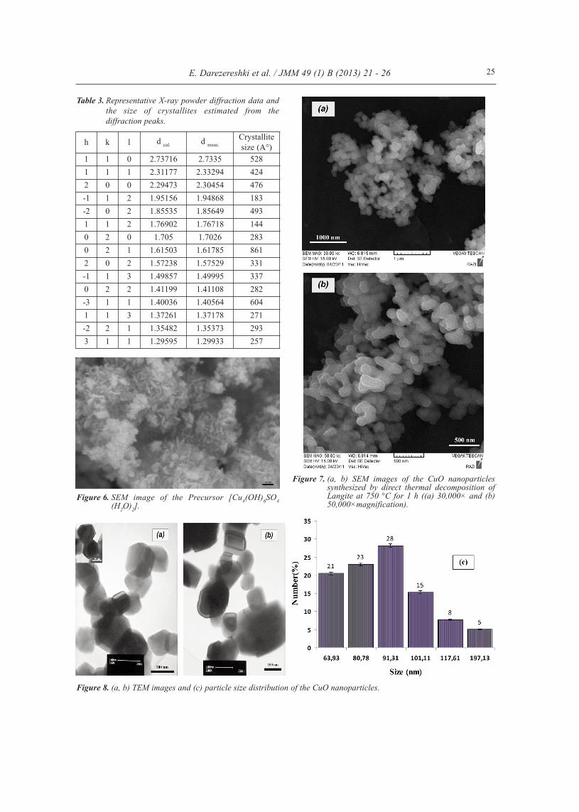
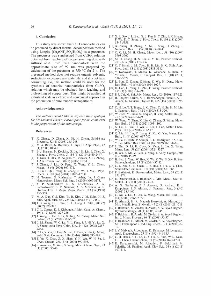
Fig. 3b shows the FTIR spectrum of the CuOnanoparticles. The absorption peak at 538 and 587cm−1 is attributed to Cu(II)–O [30], which is inagreement with the results of XRD. The SEM imagesof precursor and CuO nanoparticles are shown inFig.6 and Fig. 7, respectively. The morphology of theprecursor [Cu4(OH)6SO4(H2O)2] and nano-sized CuOnanoparticles were flower-like shape and spherical,respectively. Some of the nanoparticles becameagglomerated and sintered during heating. The TEMimage of CuO nanoparticles is shown in Fig.8a and b.TEM observations showed that the CuO nanoparticleshave a wide size distribution with the averagediameter of 92 nm (Fig. 8c).
E. Darezereshki et al. / JMM 49 (1) B (2013) 21 - 26 24
Figure 2. X-ray patterns of the Langite [Cu4(OH)6SO4(H2O)2].
Figure 3. (a) FT-infrared spectra of the precursor (Cu4(OH)6SO4(H2O)2) and (b) CuO nanoparticlesperformed by 250 mg KBr.
Figure 4. TGA–DSC curves of the precursor (Cu4(OH)6SO4(H2O)2) from 35 to 900 °C.
Figure 5. X-ray patterns of CuO nanoparticles.
CuSO Cu OH H OCuSO Cu OH CuO H O
C
4 2 2 2
4 2 2
4
32 3
2
( ) ( )( )
(CuSO Cu OH
4
4 2 ( ))2 2
2 2
2
31 2 2
2
CuO SOO H O
C2 2
3
2 1 2
C
CuO Cu O O
E. Darezereshki et al. / JMM 49 (1) B (2013) 21 - 26 25
Figure 6. SEM image of the Precursor [Cu4(OH)6SO4(H2O)2].
Figure 8. (a, b) TEM images and (c) particle size distribution of the CuO nanoparticles.
Table 3. Representative X-ray powder diffraction data andthe size of crystallites estimated from thediffraction peaks.
Figure 7. (a, b) SEM images of the CuO nanoparticlessynthesized by direct thermal decomposition ofLangite at 750 °C for 1 h ((a) 30,000× and (b)50,000×magnification).
4. Conclusion
This study was shown that CuO nanoparticles canbe produced by direct thermal decomposition methodusing Langite [Cu4(OH)6SO4(H2O)2] as a precursor.The precursor was synthesized from CuSO4 solutionobtained from leaching of copper smelting dust withsulfuric acid. Pure CuO nanoparticle with theapproximate size of 92 nm was prepared bycalcination of the precursor at 750 °C for 2 h. Thepresented method does not require organic solvents,surfactants, expensive raw materials, and it is not timeconsuming. So, this method could be used for thesynthesis of tenorite nanoparticles from CuSO4solution which may be obtained from leaching andbioleaching of copper dust. This might be applied atindustrial scale as a cheap and convenient approach inthe production of pure tenorite nanoparticles.
Acknowledgements
The authors would like to express their gratefulDr. Mohammad Hassan Fazaelipoor for his commentsin the preparation of the manuscript.
References
[1] X. Zhang, D. Zhang, X. Ni, H. Zheng, Solid-StateElectron., 52 (2) (2008) 245-248.
[2] M. A. Rafea, N. Roushdy, J. Phys. D: Appl. Phys., 42(1) (2009) 015413.
[3] B. J. Hansen, N. Kouklin, G. Lu, I. K. Lin, J. Chen, X.Zhang, J. Phys. Chem. C, 114 (6) (2010) 2440-2447.
[4] T. Kida, T. Oka, M. Nagano, Y. Ishiwata, X. G. Zheng,J. Am. Ceram. Soc., 90 (1) (2007) 107-110.
[5] J. Zhang, J. Liu, Q. Peng, X. Wang, Y. Li, Chem.Mater., 18 (4) (2006) 867-871.
[6] C. Lu, L. Qi, J. Yang, D. Zhang, N. Wu, J. Ma, J. Phys.Chem. B, 108 (46) (2004) 17825-17831.
[7] N. Topnani, S. Kushwaha, T. Athar, Int. J. GreenNanotechnol. Mater. Sci. Eng., 1 (2009) M67-M73.
[8] Y. P. Sukhorukov, N. N. Loshkareva, A. A.Samokhvalov, S. V. Naumov, A. S. Moskvin, A. S.Ovchinnikov, J. Magn. Magn. Mater., 183 (3) (1998)356-358.
[9] M. A. Dar, Y. S. Kim, W. B. Kim, J. M. Sohn, H. S.Shin, Appl. Surf. Sci., 254 (22) (2008) 7477-7481.
[10] J. B. Wang, D. H. Tsai, T. J. Huang, J. Catal., 208 (2)(2002) 370-380.
[11] C. L. Carnes, K. J. Klabunde, J. Mol. Catal. A: Chem.,194 (1-2) (2003) 227-236.
[12] J. Wang, S. He, Z. Li, X. Jing, M. Zhang, Mater. Sci.Poland, 27 (2) (2009) 501-507.
[13] L. M. Zhang, W. C. Lu, Y. L. Feng, J. P. Ni, Y . Lu, X.F. Shang, Acta Phys. Chim. Sin., 24 (12) (2008) 2257-2262.
[14] C. Li, Y. Yin, H. Hou, N. Fan, F. Yuan, Y. Shi, Q. Meng,Solid State Commun., 150 (13-14) (2010) 585-589.
[15] T. Yu, X. Zhao, Z. X. Shen, Y. H. Wu, W. H. Su, J.Cryst. Growth, 268 (3-4) (2004) 590-595.
[16] S. Anandan, X. Wen, S. Yang, Mater. Chem. Phys., 93(1) (2005) 35-40.
[17] X. P. Gao, J. L. Bao, G. L. Pan, H. Y. Zhu, P. X. Huang,F. Wu, D. Y. Song, J. Phys. Chem. B, 108 (18) (2004)5547-5551.
[18] X. Zhang, D. Zhang, X. Ni, J. Song, H. Zheng, J.Nanopart. Res., 10 (5) (2008) 839-844.
[19] C. C. Li, M. H. Chang, Mater. Lett., 58 (30) (2004)3903-3907.
[20] M. H. Chang, H. S. Liu, C. Y. Tai, Powder Technol.,207 (1-3) (2011) 378-386.
[21] C. T. Hsieh, J. M. Chen, H. H. Lin, H. C. Shih, Appl.Phys. Lett., 83 (16) (2003) 3383-3385.
[22] Y. Kobayashi, T. Maeda, K. Watanabe, K. Ihara, Y.Yasuda, T. Morita, J. Nanopart. Res., 13 (10) (2011)5365-5372.
[23] L. Sun, Z. Zhang, Z.Wang, Z. Wu, H. Dang, Mater.Res. Bull., 40 (6) (2005) 1024-1027.
[24] D. Han, H. Yang, C. Zhu, F. Wang, Powder Technol.,185 (3) (2008) 286-290.
[25] P. J. Cai, M. Shi, Adv. Mater. Res., 92 (2010), 117-123.[26] R. Ranjbar-Karimi, A. R. Bazmandegan-Shamili, A. R.
Aslani, K. Kaviani, Physica B, 405 (15) (2010) 3096-3100.
[27] C. H. Lo, T. T. Tsung, L. C. Chen, C. H. Su, H. M. Lin,J. Nanopart. Res., 7 (2-3) (2005) 313-320.
[28] W. Jisen, Y. Jinkai, S. Jinquan, B. Ying, Mater. Design,25 (7) (2004) 625-629.
[29] W. Wang, Y. Zhan, X. Liu, C. Zheng, G. Wang, Mater.Res. Bull., 37 (14) (2002) 1093-1100.
[30] N. Liu, D. Wu, H. Wu, C. Liu, F. Luo, Mater. Chem.Phys., 107 (2) (2008) 511-517.
[31] Q. Liu, H. Liu, Y. Liang, Z. Xu, G. Yin, Mater. Res.Bull., 41 (4) (2006) 697-702.
[32] W. Jia, E. Reitz, P. Shimpi, E. G. Rodriguez, P.X. Gao,Y. Lei, Mater. Res. Bull., 44 (8) (2009) 1681-1686.
[33] J. Zhu, D. Li, H. Chen, X. Yang, L. Lu, X. Wang,Mater. Lett., 58 (26) (2004) 3324-3327.
[34] R. Wu, Z. Ma, Z. Gub, Y. Yang, J. Alloy. Compd., 504(1) (2010) 45-49.
[35] H. Fan, L. Yang, W. Hua, X. Wu, Z. Wu, S. Xie, B. Zou,Nanotechnology, 15 (1) (2004) 37-42.
[36] C. L. Zhu, C. N. Chen, L. Y. Hao, Y. Hu, Z. Y. Chen,Solid State Commun., 130 (10) (2004) 681-686.
[37] F. Bakhtiari, E. Darezereshki, Mater. Lett., 65 (2011)171-174.
[38] E. Darezereshki, F. Bakhtiari, J. Min. Metall. Sect. B-Metall., 47 (1) B (2011) 73-78.
[39] A. G. Nasibulin, P. P. Ahonen, O. Richard, E. I.Kauppinen, I. S. Altman, J. Nanopart. Res., 3 (5-6)(2001) 385-400.
[40] C. Xu, Y. Liu, G. Xu, G. Wang, Mater. Res. Bull., 37(14) (2002) 2365-2372.
[41] R. Ahmadi, H. R. Madaah Hosseini, A. Masoudi, J.Min. Metall. Sect. B-Metall., 47 (2) B (2011) 211-218.
[42] F. Bakhtiari, M. Zivdar, H. Atashi, S. A. Seyed Bagheri,Hydrometallurgy, 90 (1) (2008) 40-45.
[43] F. Bakhtiari, H. Atashi, M. Zivdar, S. A. Seyed Bagheri,Int. J. Miner. Process., 86 (1) (2008) 50-57.
[44] F. Bakhtiari, H. Atashi, M. Zivdar, S. A. Seyedbagheri,M.H. Fazaelipoor, J. Ind. Eng. Chem., 17 (1) (2011) 29-35.
[45] J. Y. Malvault, J. Lopitaux, D. Delahaye, M. Lenglet, J.Appl. Electrochem., 25 (9) (1995) 841-845.
[46] C. H. Hsieh, S. L. Lo, C. Y. Hu, K. Shih, W. S. Kuan,C. L. Chen, Chemosphere, 71 (9) (2008) 1693-1700.
[47] E. Darezereshki, M. Alizadeh, F. Bakhtiari, M.Schaffie, M. Ranjbar, Appl. Clay Sci., 54 (1) (2011)107-111.
E. Darezereshki et al. / JMM 49 (1) B (2013) 21 - 26 26


![UO: Digital Strategy [ADV420]](https://static.documents.pub/doc/80x56/55a208891a28abcc788b483a/uo-digital-strategy-adv420-55a52bc3a41f9.jpg)

