19
MK-92HNAS065-01 System Manager Unit (SMU) Hardware Reference

MK-92HNAS065-01
System Manager Unit (SMU) Hardware Reference

ii
Notices and Disclaimer Copyright © 2015 Hitachi Data Systems Corporation. All rights reserved.
The performance data contained herein was obtained in a controlled isolated environment. Actual results that may be obtained in other operating environments may vary significantly. While Hitachi Data Systems Corporation has reviewed each item for accuracy in a specific situation, there is no guarantee that the same results can be obtained elsewhere.
All designs, specifications, statements, information and recommendations (collectively, "designs") in this manual are presented "AS IS," with all faults. Hitachi Data Systems Corporation and its suppliers disclaim all warranties, including without limitation, the warranty of merchantability, fitness for a particular purpose and non-infringement or arising from a course of dealing, usage or trade practice. In no event shall Hitachi Data Systems Corporation or its suppliers be liable for any indirect, special, consequential or incidental damages, including without limitation, lost profit or loss or damage to data arising out of the use or inability to use the designs, even if Hitachi Data Systems Corporation or its suppliers have been advised of the possibility of such damages.
This document has been reviewed for accuracy as of the date of initial publication. Hitachi Data Systems Corporation may make improvements and/or changes in product and/or programs at any time without notice. No part of this document may be reproduced or transmitted without written approval from Hitachi Data Systems Corporation.

iii
Document Revision Level Revision Date Description
0.0 April 2015 First publication
1.0 June 2015 Updated SMU Removal and Replacement section

Hitachi Data Systems
Table of Contents
Introduction to the SMU400 ....................................................................................................................... 2
SMU400 hardware ................................................................................................................................ 4
Introduction to the SMU300 ....................................................................................................................... 5
SMU300 hardware ................................................................................................................................ 7
Supported server releases ......................................................................................................................... 7
Port usage and connectivity ...................................................................................................................... 8
Serial port (COM1 and COM2) connection settings.............................................................................. 8 Laptop Serial/KVM Configuration .......................................................................................................... 9
SMU Removal and Replacement ............................................................................................................. 10
Obtain an SMU backup (if the original SMU GUI is NOT functional) .................................................. 10 Obtain an SMU backup (if the original SMU GUI is functional) .......................................................... 11 Configuring the Replacment SMU ...................................................................................................... 11 Replacement of the original SMU ....................................................................................................... 12 Perform a sanity check on the new replacement SMU ....................................................................... 13

2
Introduction to the SMU400 The SMU400 is a 1U rack mounted device, used to manage the servers and clusters of the Hitachi NAS Platform and the Hitachi HUS File Module storage systems.
HDS does not support component replacement, and the entire SMU should be replaced in case of hardware failures.
Figure 1: SMU400 Front View
Item Description
1 Hard disk carrier.
2 Hard disk release button. Note: Just above the hard disk release button on the disk carrier, there are two LEDs that indicate hard disk status.
1. Hard disk activity 2. Hard disk failure
3 DVD ROM.
4 USB Ports.
5 COM2, (serial connector B). COM2 can only be used at boot time, and is not available after the system has started. Note that COM1 (serial connector A) is on the rear panel.
3
Item Description
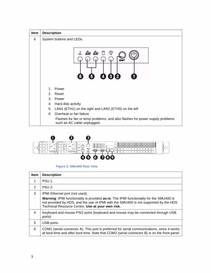
6 System buttons and LEDs.
1. Power 2. Reset 3. Power 4. Hard disk activity 5. LAN1 (ETH1) on the right and LAN2 (ETH0) on the left 6. Overheat or fan failure
Flashes for fan or temp problems, and also flashes for power supply problems such as AC cable unplugged.
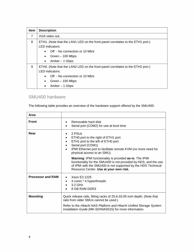
Figure 2: SMU400 Rear View
Item Description
1 PSU 1.
2 PSU 2.
3 IPMI Ethernet port (not used). Warning: IPMI functionality is provided as-is. The IPMI functionality for the SMU400 is not provided by HDS, and the use of IPMI with the SMU400 is not supported by the HDS Technical Resource Centre. Use at your own risk.
4 Keyboard and mouse PS/2 ports (keyboard and mouse may be connected through USB ports).
5 USB ports.
6 COM1 (serial connector A). This port is preferred for serial communications, since it works at boot time and after boot time. Note that COM2 (serial connector B) is on the front panel.
4
Item Description
7 VGA video out.
8 ETH1. (Note that the LAN1 LED on the front panel correlates to the ETH1 port.) LED indicators:
• Off - No connection or 10 Mb/s • Green – 100 Mbps • Amber – 1 Gbps
9 ETH0. (Note that the LAN2 LED on the front panel correlates to the ETH2 port.) LED indicators:
• Off - No connection or 10 Mb/s • Green – 100 Mbps • Amber – 1 Gbps
SMU400 hardware
The following table provides an overview of the hardware support offered by the SMU400:
Area
Front • Removable hard disk • Serial port (COM2) for use at boot time
Rear • 2 PSUs • ETH0 port to the right of ETH1 port • ETH1 port to the left of ETH0 port • Serial port (COM1) • IPMI Ethernet port to facilitate remote KVM (no more need for
physical access to an SMU).
Warning: IPMI functionality is provided as-is. The IPMI functionality for the SMU400 is not provided by HDS, and the use of IPMI with the SMU400 is not supported by the HDS Technical Resource Center. Use at your own risk.
Processor and RAM • Xeon E3 1225 • 4 cores * 4 hyperthreads • 3.2 GHz • 8 GB RAM DDR3
Mounting Quick release rails, fitting racks of 25.6-33.05 inch depth. (Note that rails from older SMUs cannot be used.)
Refer to the Hitachi NAS Platform and Hitachi Unified Storage System Installation Guide (MK-92HNAS015) for more information.

5
Introduction to the SMU300 The SMU300 is a 1U rack mounted device, used to manage the servers and clusters of the Hitachi NAS Platform and the Hitachi HUS File Module storage systems.
HDS does not support component replacement, and the entire SMU should be replaced in case of hardware failures.
Figure 3: SMU300 Front View
Item Description
1 DVD ROM.
2 System buttons and LEDs.
1. Power 2. Reset 3. Power 4. Hard disk activity 5. LAN1 (ETH0) on the right and LAN2 (ETH1) on the left 6. Overheat or fan failure
Flashes for fan or temp problems, and also flashes for power supply problems such as AC cable unplugged.
3 USB ports

6
Figure 4: SMU300 Rear View
Item Description
1 PSU.
2 Keyboard and mouse PS/2 ports (keyboard and mouse may be connected through USB ports).
3 USB ports.
4 COM1 (serial connector A). This port is preferred for serial communications, since it works at boot time and after boot time.
5 VGA video out.
6
ETH0.(left) (Note that the LAN1 LED on the front panel correlates to the ETH0 port.) LED indicators:
• Off - No connection or 10 Mb/s • Green – 100 Mbps • Amber – 1 Gbps
ETH1.(right) (Note that the LAN2 LED on the front panel correlates to the ETH1 port.) LED indicators:
• Off - No connection or 10 Mb/s • Green – 100 Mbps • Amber – 1 Gbps

7
SMU300 hardware
The following table provides an overview of the hardware support offered by the SMU300:
Area
Rear • PSU • ETH0 port to the right of ETH1 port • ETH1 port to the left of ETH0 port • Serial port (COM1)
Processor and RAM • Core2 E7500 Series • 4 GB RAM DDR2 • 2.93 Ghz
Supported server releases See Hitachi NAS Platform, NAS Operating System 12.3 Release Notes or later for the most current values.
SMU CentOS Version Supported Server Releases
Number of Supported Servers / Cluster
HNAS OS SMU 300 SMU 400
SMU 8.1 4.8.1 7.0, 8.2 5 Not supported
SMU 10.1, 10.2 6.2 8.1, 8.2, 10.0, 10.2 5 5
SMU 11.x 6.2 8.1, 8.2, 10.2, 11.x 5 5
SMU 12.x 6.2 8.1, 8.2, 10.2, 11.x, 12.x
5 5
8
Port usage and connectivity For serial (COM1 and COM2) port settings, see Serial port (COM1 and COM2) connection settings below. For all other connections, refer to the Hitachi NAS Platform and Hitachi Unified Storage System Installation guide (MK-92HNAS015) for more information.
Serial port (COM1 and COM2) connection settings • Baud rate: 115200 (may need to set in terminal emulator application) • Data: 8 bits • Parity: None • Stop bits: 1 bit • Flow Control: None

9
Laptop Serial/KVM Configuration 1. Make a connection to the external SMU
Note: On newer notebooks, you will need a USB to serial dongle and a 9-pin DB9 null modem cable. This is the preferred method, as it will allow you to capture the output to a file when using a Putty serial connection.
a. Open a SERIAL Putty session: i. Putty configuration
1. Select the Serial Radio Button 2. Enter the COM port that your serial dongle is using 3. Enter 115200 in the Speed box. 4. Click on Serial in the Category Tree on the left 5. Make sure the Speed is 115200 6. Set the Data bits to 8 7. Set the Stop bits to 1 8. Set the Parity to None 9. Set the Flow Control to None 10. Click on Session in the Category Tree on the left 11. Enter SMU serial (or similar in the Saved Sessions box 12. Click the Save button
ii. Turn on the putty session logging 1. Click on Logging from the Category Tree on the left 2. Select “Printable output” in Session logging. 3. Set the location for the putty output file 4. In the section What to do if the log file already exists; select
“Ask the user every time” 5. Click on “Session” from the Category Tree on the left, which
returns you to the Session window 6. Click on the Save button
b. KVM Connection - Connect a monitor, keyboard and mouse to the appropriate ports on the back of the SMU.

10
SMU Removal and Replacement The following sections provide the procedure for removing and replacing the SMU.
HDS does not support component replacement, and the entire SMU should be replaced in case of hardware failures.
Obtain an SMU backup (if the original SMU GUI is NOT functional) Perform the following steps to recover a backup file from a malfunctioning SMU (if you can get to a Debian Linux prompt).
Prerequisites 1. KVM or Laptop with putty installed 2. USB stick 3. Replacement SMU
Login to the SMU 1. Connect a KVM or Serial cable to the SMU 2. At the Login Prompt Login as username: root password: nasadmin
Connect and mount the USB stick 1. Connect the USB drive to a USB port on the SMU 2. Run the fdisk -l command. The last line in this command should show you the device
name of the USB key (e.g. /dev/sdb1). This line should show a device that matches the size and configuration of the USB key
3. Enter mount /dev/sdb1 /mnt
Copy the SMU backup file to the USB stick (ie. smu_01May15_010000.zip) 1. Change to the backup directory of the SMU
a. cd /var/opt/smu/archive/smu-backup/<ip address of the local SMU> 2. List the SMU backup files
a. ls -l 3. Copy the SMU backup file to the /mnt directory (USB stick)
a. cp /<latest SMU backup .zip file> /mnt
Unmount the USB stick 1. Execute umount /mnt 2. Remove the USB stick from the old SMU 3. The USB stick can now be used to recover the SMU configuration to the Replacement
SMU

11
Obtain an SMU backup (if the original SMU GUI is functional)
1. On the original SMU, label all the cables. 2. Connect your laptop to the private management switch.
a. Configure the laptop ip address: i. IP address 192.0.2.150
ii. Netmask 255.255.255.0 3. Open a web browser, navigate to 192.0.2.1 and logon as Username: admin Password:
nasadmin 4. Back up the SMU.
Note: If managing a cluster, leave the original SMU powered up and cabled to provide quorum.
a. In the GUI, navigate to Home > SMU Administration > SMU Backup and Restore b. Click the Backup SMU: Backup button c. Save the configuration file to a location on your computer d. Verify that the archive file opens
Configuring the Replacment SMU 1. Set up the new SMU in a staging area first. 2. Make a connection to the external SMU.
a. Serial Connection - Connect via Putty Serial (Serial Settings 115200, 8, N, 1, N) to the serial console port
Note: On newer notebooks, you will need a USB to serial dongle and a 9-pin DB9 null modem cable. This is the preferred method, as it will allow you to capture the output to a file when using a Putty serial connection.
b. KVM Connection - Connect a monitor, keyboard and mouse to the appropriate ports on the back of the SMU
3. SMU Installation. a. Depress the red button on the front of the SMU to power the unit on b. Verify code level of the replacement SMU
i. Login as Username: root Password: nasadmin ii. Check the SMU Version.
1. Type smu-version
Note: SMU should be running the same firmware version or newer that supports the HNAS node SU. If it is not, then follow the procedure after configuring the SMU to upgrade to the latest version.

12
c. If necessary, load same firmware version or newer that supports the HNAS node SU to the SMU via CLI.
i. Equipment - USB flash drive 1. Latest SMU firmware iso file (SMUsetup_<filename>_hds.iso) 2. SMU backup file generated in Step 5
ii. Upgrade Procedure 1. It is assumed that the previous console session is still active 2. Connect the USB drive to a USB port on the SMU 3. Create a directory: mkdir /mnt2 4. Enter mount /dev/sdb1 /mnt2 5. Enter cd /mnt2 (change to the /mnt2 directory) 6. Copy the SMUsetup file from the USB to the /tmp directory
a) cp SMUsetup_<file_name>.hds.iso /tmp/ b) cp smu_date_stamp.zip /tmp/
7. Enter cd / (changes to the root directory) 8. Enter umount /mnt2 (unmounts the USB drive) 9. Remove the USB drive
d. Install the SMU Application i. Mount the SMU .iso file: • mount -o loop /tmp/SMUsetup_<filename>_hds.iso /mnt2
ii. Type /mnt2/autorun
Note: The SMU installation may take up to 20 minutes to install, followed by a reboot. Make sure you have removed the USB drive prior to rebooting.
e. Restore the SMU from the configuration backup of the old SMU: i. Login to the console connection as Username: root Password: nasadmin
ii. Enter cd /usr/local/bin (Change to the /usr/local/bin directory) iii. Start the restore: ./smu-restore -f /tmp/<smu_date_stamp.zip>
NOTE: The smu-restore process can take anywhere from 45 minutes to 2 hours. Do not interrupt the process.
iv. Enter reboot f. Once the SMU has rebooted, the logon ID displayed should be that of the old
SMU. i. Login to the console as Username: root Password: nasadmin
ii. Enter ifconfig (verify that the replacement SMU has the following ip addresses)
1. eth1 - HDS management ip address (typically 192.0.2.1) 2. eth0 - the customer management ip address
iii. Type shutdown -h now (this will power off the Replacement SMU) Replacement of the original SMU
1. Move the Serial/KVM connection to the Original SMU. 2. Login as Username: root Password: nasadmin
13
3. Type shutdown -h now (this will power off the Original SMU). 4. Physically remove the original SMU and install the replacement SMU.
Perform a sanity check on the new replacement SMU 1. Move the Serial/KVM connection to the replacement SMU. 2. Plug the cables that were removed from the original SMU into the replacement SMU.
(Note: The Replacement SMU port locations may be different. For SMU 400 port locations, refer to Figure 2, and for SMU 200 or SMU 300 port locations, refer to Figure 4.
3. Depress the red button on the front of the replacement SMU to power the unit on. 4. Login as Username: root Password: nasadmin 5. Execute ifconfig (eth0 should report the original customer IP address and eth1
should be 192.0.2.1). 6. Execute smu-version (verify the SMU version is the matching or latest version of
firmware) 7. Logout by typing exit 8. Using the ethernet connection to the HNAS management switch, open an ssh putty
session to the new SMU at 192.0.2.1 9. Login as Username: manager Password: nasadmin 10. Select the server (adminEVS) that you wish to manage from the menu (if more than one
local server is present, repeat these steps for each server)
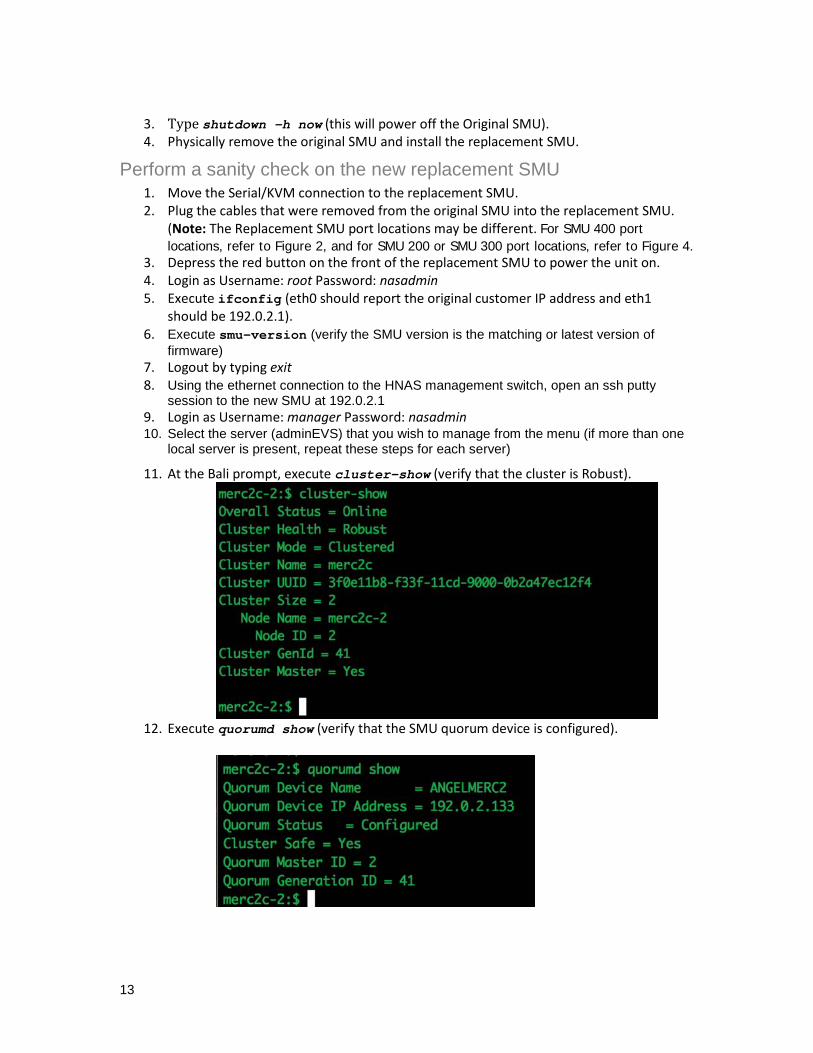
11. At the Bali prompt, execute cluster-show (verify that the cluster is Robust).
12. Execute quorumd show (verify that the SMU quorum device is configured).

14
13. If the Quorum is NOT showing Configured then do the following: a. Execute quorumd remove b. Execute quorumd add 192.0.2.1 c. Recheck the quorum status with quorumd show

15
Hitachi Data Systems
Corporate Headquarters 2845 Lafayette Street Santa Clara, California 95050-2639 U.S.A. www.hds.com
Regional Contact Information
Americas +1 408 970 1000 [email protected]
Europe, Middle East, and Africa +44 (0) 1753 618000 [email protected]
Asia Pacific +852 3189 7900 [email protected] MK-92HNMAS065-01

16


![Untitled-2 [contents.iptime.co.kr]contents.iptime.co.kr/~contents/link/NAS-I.pdf · 2018-10-01 · Windows 192.1680250 admin ipTIME NAS NAS ëë..l admin ipTIME NAS](https://static.documents.pub/doc/80x56/5f0814dc7e708231d4203dfa/untitled-2-contentslinknas-ipdf-2018-10-01-windows-1921680250-admin.jpg)


![Untitled-2 [contents.iptime.co.kr]contents.iptime.co.kr/~contents/link/NAS-II.pdf · 2018-10-01 · Windows 192.1680250 admin ipTIME NAS NAS ëë..l admin ipTIME NAS](https://static.documents.pub/doc/80x56/5ec53605e2d46f7ca85b5c6b/untitled-2-contentslinknas-iipdf-2018-10-01-windows-1921680250-admin.jpg)


