22
MULTI-ROOM SYSTEM Systemline Modular Installation Guide MULTI-ROOM SYSTEM Installation Guide
MULTI-ROOM SYSTEM
Systemline Modular Installation Guide
MULTI-ROOM SYSTEM
I n s t a l l a t i o n G u i d e
PAGE 2
Declaration of Conformity
Systemline Modular has been designed and independently tested to be in compliance with the following standards:
BS EN 60065: 1998 / IEC 60065: 1998 (safety) incl. Australian DeviationsEN 55013, EN 61000-3-2, EN 61000-3-3, EN 55020 (EMC)AZ/NZS 1053 (Australia/New Zealand emissions)47 CFR part 15 (FCC for United States)
Nemko LVD Certifi cateEMC/AZ/NZS/FCC (including SEQAL EMC Certifi cate & Test Report)CB Report: (including CENELEC modifi cations and national deviations for Europe)AUS/NZ deviations CB report appendix: CB Certifi cation.
Safety
This Symbol is to alert the user to the presence of dangerous voltages inside the Systemline Modular Power supplies. To reduce the risk of electric shock do not dismantle these power supplies.
This symbol is to alert the user of important operating instructions included on the CD-Rom accompanying the Systemline Modular.
Read all the instructions before connecting or operating the Systemline Modular. Pay particular attention to the safety information. Keep this manual so you can refer to the safety instructions.
WARNING: There are no user serviceable parts inside. Refer all servicing issues to qualifi ed personnel.
WARNING: To reduce the risk of fi re or electric shock, do not expose the Systemline Modular to moisture or water. Do not allow foreign object to get into any part of Systemline modular. If moisture or foreign bodies get inside any part, immediately disconnect the power cord from the wall. Obtain assistance from a qualifi ed service person. No objects fi lled with liquids, such as vases, shall be placed on any part of Systemline Modular.
That no naked fl ame sources such as candles should be placed on any part of Systemline Modular.
Ventilation should not be impeded.
Ensure that the Systemline modular components are fi tted in accordance with their individual installation instructions.

PAGE 3
Copyright and acknowledgementsCopyright © 2002 QED Audio Products Ltd. All rights reserved.
The information in this guide is believed to be correct as of the date of publication. However, our policy is one of continuous development and so the information is subject to change without notice, and does not represent a commitment on the part of QED Audio Products Ltd.
Systemline is a registered trademark of QED Audio Products Ltd. Sistema 45 and System 45 are trademarks of AVE s.p.A. All other product names are trademarks or registered trademarks of their respective owners.
QED Audio Products LtdUnit 16, Woking Business ParkAlbert DriveWokingSurrey GU21 5JY
Web: www.qed.co.uk
Terminology This guide uses the following terminology to refer to the components of the Systemline Modular system:
Zone: an audio system in a remote room or location, typically consisting of a pair of Systemline Modular ceiling-mounted speakers and an optional keypad, able to play music either from the remote system or a local source.
Main zone: the zone connected directly to the remote system.
Sub-zone: a zone connected as a spur off a main zone.
Remote system: the hi-fi system providing audio distributed to each zone.
Hub: distributes audio to and infra-red signals from multiple zones, required in systems with more than one main zone.
Multi-room system: An audio or audio visual system that can be used in any room in the home. Sometimes colloquially referred to as a built-in sound system or distributed audio system.
Expanded zone: A zone where multiple active speakers are used to distribute sound over a large area, usually with synchronised volume control. An expanded zone can also be confi gured with two or more areas of independent volume control (via separate keypad control).
Multi-source multi-zone: A system where different audio sources can be played in different rooms simultaneously
System room: The location of the hi-fi system providing the audio sources to be distributed via Systemline Modular.
Local input: Each zone or sub-zone can accept a local stereo audio input. This input can only be listened to in that zone, hence the term local. The actual location of the audio source need not be local, it could be in another room or other discreet location.
About this guideThis Systemline Modular System Installation Guide is aimed at audio installation engineers, or trained qualifi ed electricians, involved in the actual installation and interconnection of a Systemline Modular system. It consists of the following chapters:
Preparing for the installation gives information about preparing for a Systemline Modular installation, including details of the tools and equipment needed.
Terminating the wiring and fi tting the
Systemline Modular components describes how to connect and fi t all of the components into a pre-wired home.
Testing the system gives recommended test procedures to enable you to verify that the Systemline Modular multi-room system has been installed correctly.
Confi guring the system gives information about further customisations necessary for sub-zones and expanded zones.
Troubleshooting gives suggested solutions to problems that may occur with the system.
Finally, Operating the system gives basic operating instructions for the Systemline Modular System.
Tab
le o
f C
on
ten
ts
PAGE 4
1 Preparing for the
installation 5
1.1 Preparing for the installation 5
Tools and equipment 5
2 Terminating the wiring
and fi tting the Systemline
Modular Components 6
2.1 Preface 6
2.2 Locating the speaker positions in each zone 7
Locating concealed cables 7Clearance 7Beware of joists 7
2.3 Cutting holes for ceiling speakers 8
2.4 Connecting the active (right-channel) ceiling
speaker 8
Connecting the system input 9Connecting the keypad 9Connecting the feed to the passive speaker 9Spare cable 9
2.5 Connections required for additional
functionality 9
Local input 9Power supply 10Next (sub-zone) zone 10
2.6 Confi guring the active speaker 10
Mono operation 10Disabling the LED display on IR equipped speakers 10
2.7 Connecting the PLM2 passive speaker 10
2.8 Fitting the speaker into the ceiling 11
2.9 Fitting and connecting the KPM1 keypad (if
specifi ed) 11
Changing the keypad default setting 122.10 Fitting and connecting the local input SIM &
IRM modules (if specifi ed) 12
2.11 Fitting and connecting the hub 13
Mounting the hub and PSU 132.12 Connecting a hi-fi system or music source
component 13
Directly connected music source 13Remotely connected music source 13
2.13 Connecting the PIM power input module for
sub-zones 14
2.14 Wiring for a single-zone system (no hub) 14
3 Testing the system 15
3.1 Test procedure 15
3.2 Completing the installation 15
4 Confi guring the system 16
4.1 Setting bass, treble, and minimum/maximum
volume levels 16
4.2 Setting the active speaker for mono
operation 16
4.3 Deactivating the LED display on an IR
equipped speaker 17
4.4 Setting the keypad to enable local input
toggle 17
4.5 Changing addresses for sub-zones and
expanded zones 17
Changing module addresses 184.6 Changing the hub setting to accept a direct
input 18
5 Troubleshooting 19
Golden rule 19Speaker will not come out of standby. The red standby indicator blinks continuously 19Speaker will not come out of standby. Red standby indicator remains illuminated 19Speaker switches on, with the blue indicator illuminated, but there is no sound 19Testing sub-zones 19Sound breaks up and becomes unstable at high volume settings 19Some zones sound too loud when fi rst switched on 20
6 Operating the system 21
Turning a zone on 21To adjust the listening volume 21To select the local source 21To switch back to system input 21To mute the system 21To switch the zone off 21Sub-zone operation – independent operation 21
PAGE 5
Sec
tio
n 1
• P
rep
arin
g f
or
the
inst
alla
tio
n
1 Preparing for the installationThis chapter gives information about preparing for a Systemline Modular installation, including details of the tools and equipment needed.
1.1 Preparing for the installation
The starting point for this manual is an already pre-wired home. If that is not the case, please refer to the Systemline Modular planning manual, which describes in detail how to plan an installation to fi rst fi x stage. It also includes a description and specifi cation of each product.
Before starting the installation, please ensure that you refer to the wiring schedule (or equivalent document) that details exactly how the home has been pre-wired. A wiring schematic, and parts list should also be available. We recommend that you ensure that you have everything that you need before commencing the installation.
In addition to the Systemline Modular components, you will also need the following tools and accessories:
Tools and equipment
• CAT5/CAT6 cable cutting and stripping tools.
• Cable tester for checking CAT5 cabling for open circuits and short-circuits.
• IDC CAT5 Katts punch-down tool type 110.
• Jigsaw or pad saw for cutting holes for ceiling mounting speakers.
• Tools for drilling and fi xing wall mounting boxes.
• Tone generator and cable locating tool.
• Miscellaneous tools, screwdrivers etc.
PAGE 6
Sec
tio
n 2
• T
erm
inat
ing
th
e w
irin
g
2.1 Preface
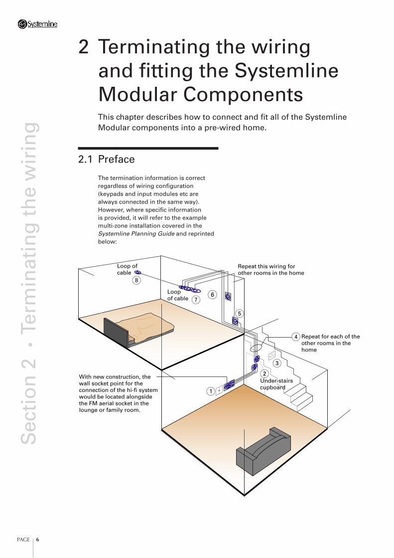
The termination information is correct regardless of wiring confi guration (keypads and input modules etc are always connected in the same way). However, where specifi c information is provided, it will refer to the example multi-zone installation covered in the Systemline Planning Guide and reprinted below:
Under-stairscupboard
With new construction, thewall socket point for the connection of the hi-fi systemwould be located alongsidethe FM aerial socket in thelounge or family room.
Loop of cable
Loopof cable
Repeat for each of theother rooms in thehome
Repeat this wiring forother rooms in the home
(2
(1
(3
(4
(5
(6(7
(8
2 Terminating the wiring and fi tting the Systemline Modular ComponentsThis chapter describes how to connect and fi t all of the Systemline Modular components into a pre-wired home.
PAGE 7
Sec
tio
n 2
• T
erm
inat
ing
th
e w
irin
g
2.2 Locating the speaker positions in each zone
Unless the cables for the ceiling speakers have been left hanging out of the ceiling (as is common with light fi ttings), it will be necessary to locate these positions. The easiest way is to refer to the marked-up position of the speakers in the plan of the home. This should have been done as part of the fi rst fi x installation. If that is not the case, the following method should be used to trace the position of the cables.
Locating concealed cables
A Cable Tone Test set, available from electrical wholesalers, can be used to locate concealed cables.
Connect the tone generator to the cable being tested at the hub location (noting the correct label for a given room; see Wiring schedule in the Systemline Planning Guide), and move the probe over the ceiling of the selected zone room until the tone reaches its peak sound level. The cable should be directly above the plasterboard at this point.
Note: The above cable tracing technique will not work with foil-screened stud walling, metal wall tiles or ceiling panels.
It is recommended that you tackle one zone room at a time.
Once the speaker positions have been located and marked on the ceiling by way of a cross, check the following considerations. Remember also, that for some small rooms such as ensuite bathrooms, only a single mono speaker may have been provided for.
Clearance
Drill a small diameter hole in the ceiling at the marked point and check, using a thin screwdriver or thin rod as a measuring tool, that there is at least 90mm depth from the front surface of the ceiling to the back.
In the very rare instance that there is insuffi cient depth, the speakers can be mounted protruding below the ceiling using a suitable spacer. For more
information contact QED Audio Products Ltd.
Beware of joists
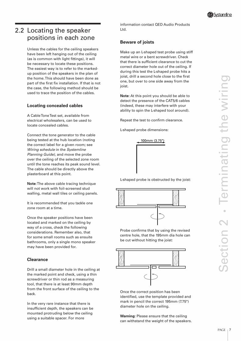
Make up an L-shaped test probe using stiff metal wire or a bent screwdriver. Check that there is suffi cient clearance to cut the correct diameter hole out of the ceiling. If during this test the L-shaped probe hits a joist, drill a second hole close to the fi rst one, but over to one side away from the joist.
Note: At this point you should be able to detect the presence of the CAT5/6 cables (indeed, these may interfere with your ability to spin the L-shaped tool around).
Repeat the test to confi rm clearance.
L-shaped probe dimensions:
100mm (3.75")
L-shaped probe is obstructed by the joist:
Probe confi rms that by using the revised centre hole, that the 195mm dia hole can be cut without hitting the joist:
Once the correct position has been identifi ed, use the template provided and mark in pencil the correct 195mm (7.75") diameter hole on the ceiling.
Warning: Please ensure that the ceiling can withstand the weight of the speakers.
PAGE 8
Sec
tio
n 2
• T
erm
inat
ing
th
e w
irin
gThis will not be a problem with new or good condition ceilings, but beware of old or cracked ceilings. Also ensure that if the relevant building regulations call for the ceiling speakers to be boxed-in or fi tted with a fi reproof cover, that this is adhered to. This is sometimes required to maintain the integrity of the fi re rating of the ceiling.
2.3 Cutting holes for ceiling speakers
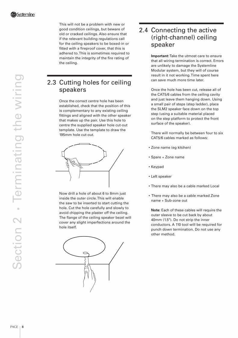
Once the correct centre hole has been established, check that the position of this is complementary to any existing ceiling fi ttings and aligned with the other speaker that makes up the pair. Use this hole to centre the supplied speaker hole cut-out template. Use the template to draw the 195mm hole cut-out.
Now drill a hole of about 6 to 8mm just inside the outer circle. This will enable the saw to be inserted to start cutting the hole. Cut the hole carefully and slowly to avoid chipping the plaster off the ceiling. The fl ange of the ceiling speaker bezel will cover any slight imperfections around the hole itself.
2.4 Connecting the active (right-channel) ceiling speaker
Important: Take the utmost care to ensure that all wiring termination is correct. Errors are unlikely to damage the Systemline Modular system, but they will of course result in it not working. Time spent here can save much more time later.
Once the hole has been cut, release all of the CAT5/6 cables from the ceiling cavity and just leave them hanging down. Using a small pair of steps (step ladder), place the SLM2 speaker face down on the top step (using a suitable material placed on the step platform to protect the front surface of the speaker).
There will normally be between four to six CAT5/6 cables marked as follows:
• Zone name (eg kitchen)
• Spare + Zone name
• Keypad
• Left speaker
• There may also be a cable marked Local
• There may also be a cable marked Zone name + Sub-zone out
Note: Each of these cables will require the outer sleeve to be cut back by about 40mm (1.5"). Do not strip the inner conductors. A 110 tool will be required for punch down termination. Do not use any other method.
PAGE 9
Sec
tio
n 2
• T
erm
inat
ing
th
e w
irin
g
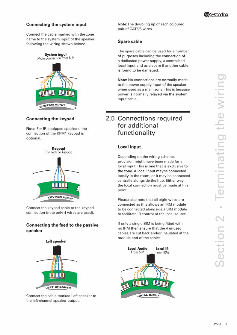
Connecting the system input
Connect the cable marked with the zone name to the system input of the speaker following the wiring shown below:
System inputMain connection from hub
Connecting the keypad
Note: For IR equipped speakers; the connection of the KPM1 keypad is optional.
KeypadConnects to keypad
Connect the keypad cable to the keypad connection (note only 4 wires are used).
Connecting the feed to the passive
speaker
Left speaker
Connect the cable marked Left speaker to the left-channel speaker output.
Note: The doubling up of each coloured pair of CAT5/6 wires
Spare cable
The spare cable can be used for a number of purposes including the connection of a dedicated power supply, a centralised local input and as a spare if another cable is found to be damaged.
Note: No connections are normally made to the power supply input of the speaker when used as a main zone. This is because power is normally relayed via the system input cable.
2.5 Connections required for additional functionality
Local input
Depending on the wiring scheme, provision might have been made for a local input. This is one that is exclusive to the zone. A local input maybe connected locally in the room, or it may be connected centrally alongside the hub. Either way, the local connection must be made at this point.
Please also note that all eight wires are connected as this allows an IRM module to be connected alongside a SIM module to facilitate IR control of the local source.
If only a single SIM is being fi tted with no IRM then ensure that the 4 unused cables are cut back and/or insulated at the module end of the cable:
Local AudioFrom SIM
Local IRFrom IRM
PAGE 10
Sec
tio
n 2
• T
erm
inat
ing
th
e w
irin
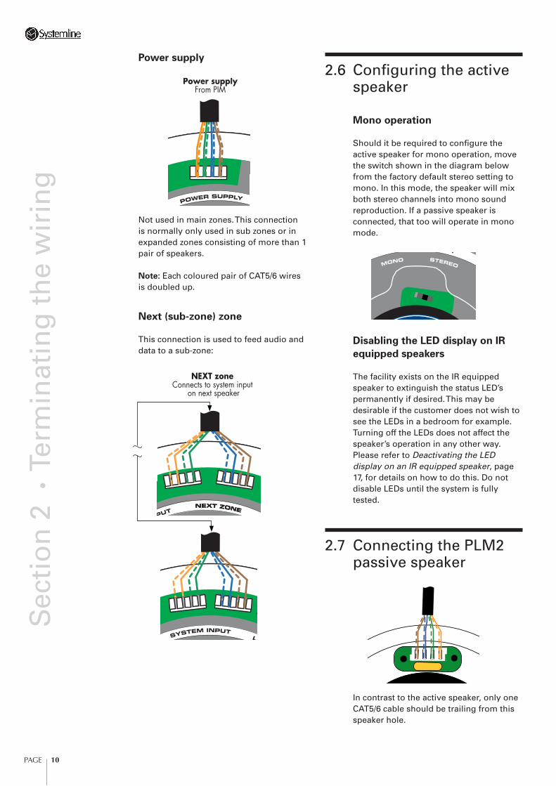
gPower supply
Power supplyFrom PIM
Not used in main zones. This connection is normally only used in sub zones or in expanded zones consisting of more than 1 pair of speakers.
Note: Each coloured pair of CAT5/6 wires is doubled up.
Next (sub-zone) zone
This connection is used to feed audio and data to a sub-zone:
NEXT zoneConnects to system input
on next speaker
2.6 Confi guring the active speaker
Mono operation
Should it be required to confi gure the active speaker for mono operation, move the switch shown in the diagram below from the factory default stereo setting to mono. In this mode, the speaker will mix both stereo channels into mono sound reproduction. If a passive speaker is connected, that too will operate in mono mode.
Disabling the LED display on IR
equipped speakers
The facility exists on the IR equipped speaker to extinguish the status LED’s permanently if desired. This may be desirable if the customer does not wish to see the LEDs in a bedroom for example. Turning off the LEDs does not affect the speaker’s operation in any other way. Please refer to Deactivating the LED display on an IR equipped speaker, page 17, for details on how to do this. Do not disable LEDs until the system is fully tested.
2.7 Connecting the PLM2 passive speaker
In contrast to the active speaker, only one CAT5/6 cable should be trailing from this speaker hole.
PAGE 11
Sec
tio
n 2
• T
erm
inat
ing
th
e w
irin
g
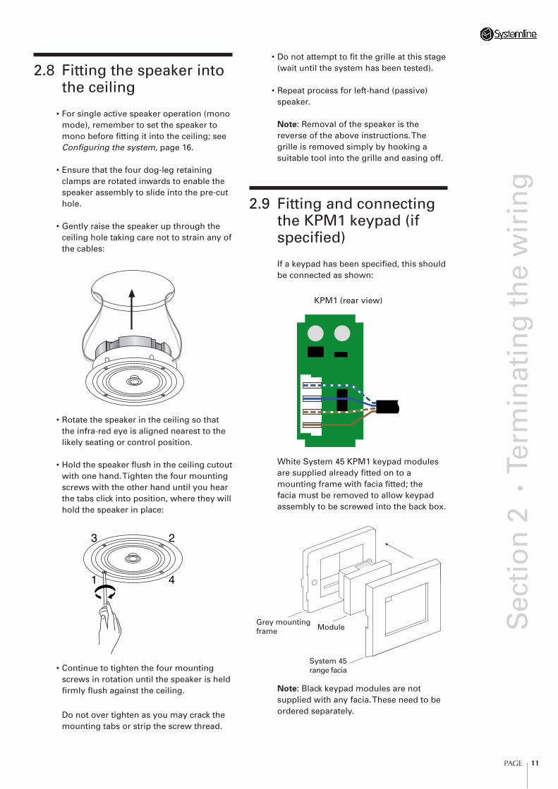
2.8 Fitting the speaker into the ceiling
• For single active speaker operation (mono mode), remember to set the speaker to mono before fi tting it into the ceiling; see Confi guring the system, page 16.
• Ensure that the four dog-leg retaining clamps are rotated inwards to enable the speaker assembly to slide into the pre-cut hole.
• Gently raise the speaker up through the ceiling hole taking care not to strain any of the cables:
• Rotate the speaker in the ceiling so that the infra-red eye is aligned nearest to the likely seating or control position.
• Hold the speaker fl ush in the ceiling cutout with one hand. Tighten the four mounting screws with the other hand until you hear the tabs click into position, where they will hold the speaker in place:
23
41
• Continue to tighten the four mounting screws in rotation until the speaker is held fi rmly fl ush against the ceiling.
Do not over tighten as you may crack the mounting tabs or strip the screw thread.
• Do not attempt to fi t the grille at this stage (wait until the system has been tested).
• Repeat process for left-hand (passive) speaker.
Note: Removal of the speaker is the reverse of the above instructions. The grille is removed simply by hooking a suitable tool into the grille and easing off.
2.9 Fitting and connecting the KPM1 keypad (if specifi ed)
If a keypad has been specifi ed, this should be connected as shown:
KPM1 (rear view)
White System 45 KPM1 keypad modules are supplied already fi tted on to a mounting frame with facia fi tted; the facia must be removed to allow keypad assembly to be screwed into the back box.
Grey mountingframe Module
System 45range facia
Note: Black keypad modules are not supplied with any facia. These need to be ordered separately.

PAGE 12
Sec
tio
n 2
• T
erm
inat
ing
th
e w
irin
gChanging the keypad default
setting
Note: The following section is included to indicate that some setup may be required although it will not be possible until the system is powered up and tested.
The factory default setting for the keypad is for the local input toggle to be disabled. If therefore, you plan to use a local input and wish to select it via the keypad you will need to enable this feature.
To set the keypad to this mode:
• Make sure that the keypad is operating normally, put the zone into standby – red LED ON.
• Depress the O and VOL+ keys on the keypad simultaneously (both together at exactly the same time). Hold briefl y until you see the status LEDs fl ash.
The LEDs will fl ash to show you the new sequence which is Blue * Green * Blue * Red (Mode 2 Local enabled).
To revert to the original Mode 1 (local disabled) repeat the process and the LED will fl ash Red* Blue * Red * Blue.
2.10 Fitting and connecting the local input SIM & IRM modules (if specifi ed)
If a local input has been specifi ed, and is located within the zone, it should be connected as shown:
SIM (rear view)
IRM (rear view)
PAGE 13
Sec
tio
n 2
• T
erm
inat
ing
th
e w
irin
g
White System 45 SIM & IRM modules are supplied already fi tted on to a mounting frame with facia fi tted. The facia must be removed to allow assembly to be screwed into the back box.
Grey mountingframe Module
System 45range facia
Repeat the above process for all other zones.
2.11 Fitting and connecting the hub
The example given assumes that connection to the hub will be via a patch panel in which case the patch panel should be wired to accept a connection from each of the zone rooms and should be marked accordingly. Please note, that if there is a likelihood that the spare cables from each zone are to be used, these should also be connected to the patch panel. If a patch panel is not used, it will be necessary to terminate the cables from each zone into RJ-45 plugs. This should follow EIA/TIA 568B (identical to AT&T 258A) standard.
Mounting the hub and PSU
The HM1 hub may be screwed directly to the wall using the mounting brackets provided, or fi tted into a structured wiring cabinet using alternative brackets (check web site for details of separately available brackets to fi t a variety of structured wiring systems).
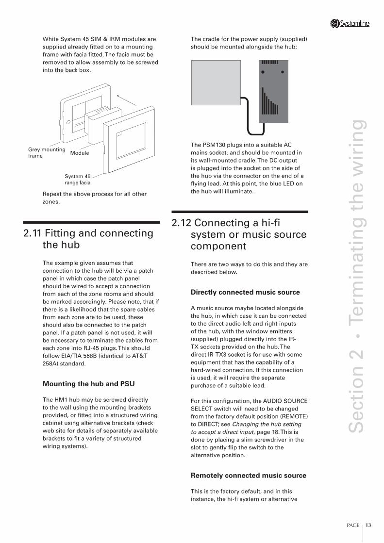
The cradle for the power supply (supplied) should be mounted alongside the hub:
The PSM130 plugs into a suitable AC mains socket, and should be mounted in its wall-mounted cradle. The DC output is plugged into the socket on the side of the hub via the connector on the end of a fl ying lead. At this point, the blue LED on the hub will illuminate.
2.12 Connecting a hi-fi system or music source component
There are two ways to do this and they are described below.
Directly connected music source
A music source maybe located alongside the hub, in which case it can be connected to the direct audio left and right inputs of the hub, with the window emitters (supplied) plugged directly into the IR-TX sockets provided on the hub. The direct IR-TX3 socket is for use with some equipment that has the capability of a hard-wired connection. If this connection is used, it will require the separate purchase of a suitable lead.
For this confi guration, the AUDIO SOURCE SELECT switch will need to be changed from the factory default position (REMOTE) to DIRECT; see Changing the hub setting to accept a direct input, page 18. This is done by placing a slim screwdriver in the slot to gently fl ip the switch to the alternative position.
Remotely connected music source
This is the factory default, and in this instance, the hi-fi system or alternative
PAGE 14
Sec
tio
n 2
• T
erm
inat
ing
th
e w
irin
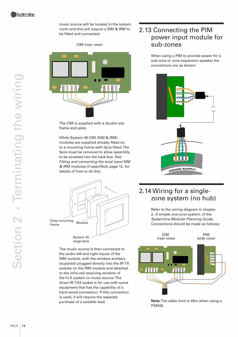
gmusic source will be located in the system room and this will require a SIM & IRM to be fi tted and connected:
CIM (rear view)
The CIM is supplied with a double size frame and plate.
White System 45 CIM (SIM & IRM) modules are supplied already fi tted on to a mounting frame with facia fi tted. The facia must be removed to allow assembly to be screwed into the back box. See Fitting and connecting the local input SIM & IRM modules (if specifi ed), page 12, for details of how to do this.
Grey mountingframe Module
System 45range facia
The music source is then connected to the audio left and right inputs of the SIM module, with the window emitters (supplied) plugged directly into the IR-TX sockets on the IRM module and attached to the infra-red receiving window of the hi-fi system or music source. The direct IR-TX3 socket is for use with some equipment that has the capability of a hard-wired connection. If this connection is used, it will require the separate purchase of a suitable lead.
2.13 Connecting the PIM power input module for sub-zones
When using a PIM to provide power for a sub-zone or zone expansion speaker the connections are as shown:
2.14 Wiring for a single-zone system (no hub)
Refer to the wiring diagram in chapter 2, A simple one-zone system, of the Systemline Modular Planning Guide. Connections should be made as follows:
CIM PIM (rear view) (side view)
Note: The cable limit is 40m when using a PSM45.
PAGE 15
Sec
tio
n 3
• T
esti
ng
th
e sy
stem
3 Testing the system This chapter gives recommended test procedures to enable you to verify that the Systemline Modular multi-room system has been installed correctly and is operating to specifi cation.
• Finally, using the original remote that was supplied with the hi-fi system, take it to each of the zone rooms in turn and check that the system can be controlled via the infrared link. To check this, try skipping tracks on the CD player for example.
• To return any zone to standby, just press the O key on the remote or keypad. The Keypad and/or speaker LED where provided will change back to red. Note: If the local system input is active you may need to press the O key twice to reach standby.
3.2 Completing the installation
To complete the installation, go to each zone room in turn and fi t the grilles to the ceiling speakers. Screw all keypads and wall modules into their back boxes and fi t the facia plates.
Important: When fi tting the grilles to the active speakers (regardless of whether the IR is enabled or not) it is vitally important to align the badge on the grille with the corresponding small circuit board visible from the front of the speaker. The grille without the badge should be used for the passive speaker.
3.1 Test procedure
• Using a patch cord (assuming that a patch panel has been used) connect the system input from the system room to the RJ-45 socket on the hub marked REMOTE AUDIO
IN. This connection is not required if the direct input to the hub is used.
• Using a patch cord (assuming a patch panel has been used), connect the fi rst zone room socket on the patch panel to the zone 1 input on the hub. Do not at this stage connect any other zones.
• Ensure that the hi-fi system is connected to either the direct input or remote input (see Terminating the wiring, page 6) and that a continuous music source is playing (CD or radio).
• Go to the zone 1 room. The keypad LED should be red (IR enabled speakers will also display the same colour LED).
• Using the RM1 remote or KPM1 keypad, press the O key and the LED will change from red to blue. The zone is now on and you should be able to hear music playing through both the left and right channel speakers. Check the VOL+/– function and Mute (RM1 only).
• Repeat the process to connect all other zones.
• If at any point the system fails to respond as described, unplug the power supply from the hub (or simply switch it off at the wall socket) and refer to Troubleshooting, page 19.
• Once each zone is operating in the correct way, plug in a local music source (where provision has been made) to check each local input. Press the L key on the RM1 remote, and the LED will change to green. This indicates that local input has been selected. Note: The zone must be on to select local input.
PAGE 16
Sec
tio
n 4
• C
on
fi g
uri
ng
th
e sy
stem
4 Confi guring the systemIn most instances, no further confi guration will be necessary. The product will operate immediately, providing that it is wired correctly. However, if sub-zones or expanded zones are specifi ed, it will be necessary to confi gure the system. There is also considerable scope to further customise the installation.
4.1 Setting bass, treble, and minimum/maximum volume levels
One of the features of Systemline Modular is the ability to set up the audio parameters for each active speaker pair. For example if you want to up the bass and reduce the treble in the bedroom or limit the maximum volume in the children’s bedroom it can be done.
The parameters that can be adjusted are as follows in this order:
• Turn on Volume
• Bass
• Treble
• Max Volume
To setup the speaker carry out the following steps:
• Ensure that the zone is operating correctly using the remote and audio can be heard.
• Turn the speaker zone ON using the remote O key.
The blue LED will illuminate.
• Depress the L and O keys on the remote simultaneously.
A green LED will fl ash three times and illuminate alongside the blue LED. If this doesn’t happen try again. The speaker system is now in setup mode.
• Using the VOL+ and VOL– keys on the remote adjust the volume to a level that you want the system to turn ON at. This will be the turn ON volume.
• Press the Mute key once to step to the next parameter. The green LED will fl ash twice.
• Using the VOL+ and VOL– keys on the remote adjust the bass lift/cut to a level that you want the speakers adjusted to.
• Press the Mute key once to step to the next parameter. The green LED will fl ash twice.
• Using the VOL+ and VOL– keys on the remote adjust the Treble lift/cut to a level that you want the speakers adjusted to.
• Press the Mute key once to step to the next parameter. The green LED will fl ash twice.
• Using the VOL+ and VOL– keys on the remote adjust the Maximum Volume level that you want the speakers to reach.
• Press the Mute key once to step to the next parameter. The green LED will fl ash three times and the speaker will reset to standby – ready for use.
Important Note: If a parameter does not require adjustment, simply press the Mute key to skip to the next one.
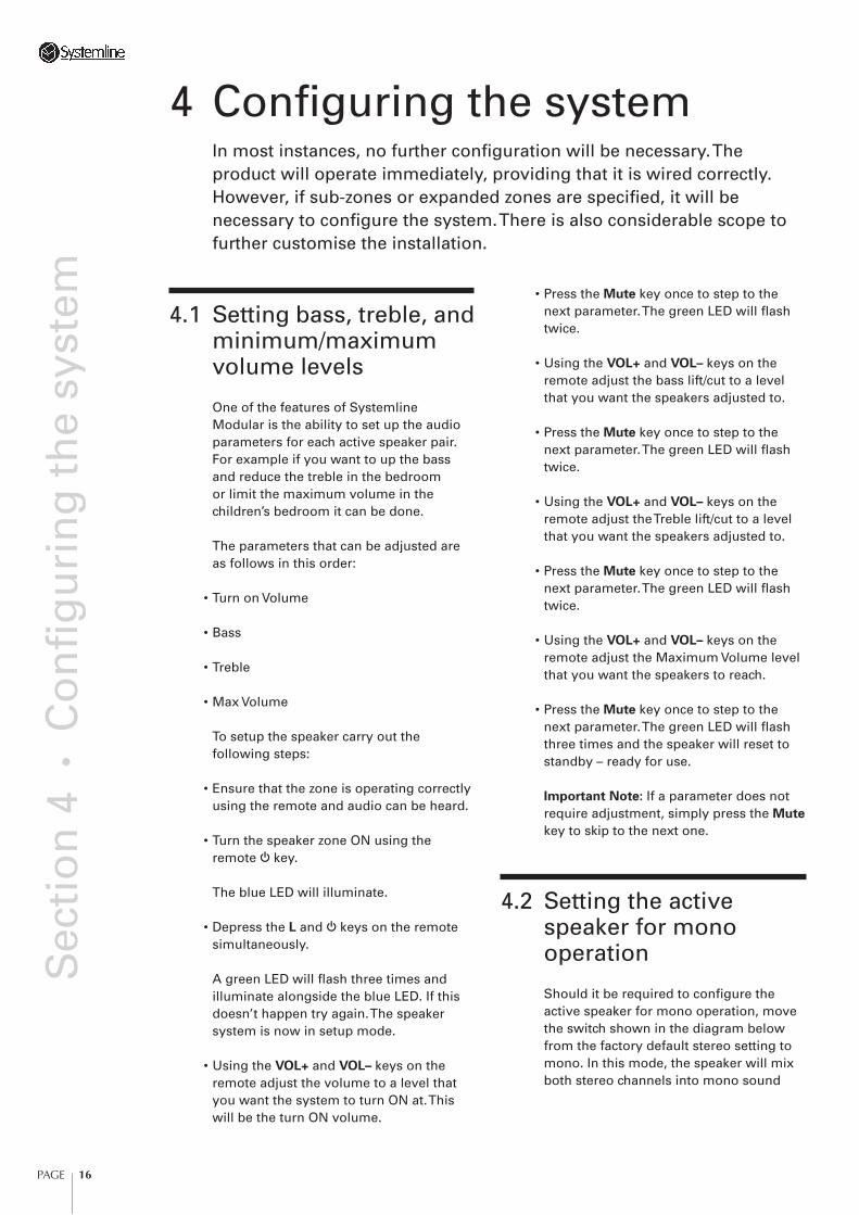
4.2 Setting the active speaker for mono operation
Should it be required to confi gure the active speaker for mono operation, move the switch shown in the diagram below from the factory default stereo setting to mono. In this mode, the speaker will mix both stereo channels into mono sound
PAGE 17
Sec
tio
n 4
• C
on
fi g
uri
ng
th
e sy
stem
reproduction. If a passive speaker is connected, that too will operate in mono mode.
4.3 Deactivating the LED display on an IR equipped speaker
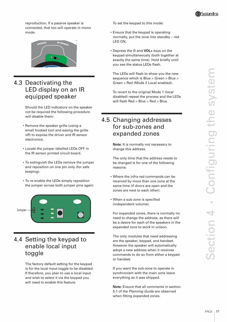
Should the LED indicators on the speaker not be required the following procedure will disable them:
• Remove the speaker grille (using a small hooked tool and easing the grille off) to expose the driver and IR sensor electronics.
• Locate the jumper labelled LEDs OFF in the IR sensor printed circuit board.
• To extinguish the LEDs remove the jumper and reposition on one pin only (for safe keeping).
• To re-enable the LEDs simply reposition the jumper across both jumper pins again:
Jumper
4.4 Setting the keypad to enable local input toggle
The factory default setting for the keypad is for the local input toggle to be disabled. If therefore, you plan to use a local input and wish to select it via the keypad you will need to enable this feature.
To set the keypad to this mode:
• Ensure that the keypad is operating normally, put the zone into standby – red LED ON.
• Depress the O and VOL+ keys on the keypad simultaneously (both together at exactly the same time). Hold briefl y until you see the status LEDs fl ash.
The LEDs will fl ash to show you the new sequence which is Blue > Green > Blue > Green > Red (Mode 2 Local enabled).
To revert to the original Mode 1 (local disabled) repeat the process and the LEDs will fl ash Red > Blue > Red > Blue.
4.5 Changing addresses for sub-zones and expanded zones
Note: It is normally not necessary to change this address.
The only time that the address needs to be changed is for one of the following reasons:
• Where the infra-red commands can be received by more than one zone at the same time (if doors are open and the zones are next to each other).
• When a sub-zone is specifi ed (independent volume).
For expanded zones, there is normally no need to change the address, as there will be a desire for each of the speakers in the expanded zone to work in unison.
The only modules that need addressing are the speaker, keypad, and handset. However the speaker will automatically adopt a new address when it receives commands to do so from either a keypad or handset.
If you want the sub-zone to operate in synchronism with the main zone leave everything as it was shipped.
Note: Ensure that all comments in section 5.1 of the Planning Guide are observed when fi tting expanded zones.
PAGE 18
Sec
tio
n 4
• C
on
fi g
uri
ng
th
e sy
stem
Changing module addresses
The only modules that need to be addressed are the speaker, keypad and remote. Address changing is very easy. There are no dip-switches to set and all modules can have their address changed without removing the module from the
wall (if it’s already installed).
Remote/Speaker
Note: Don’t change the address unless you need to for independent sub-zone operation.
• Press the O and Mute keys down simultaneously (both together at exactly the same time), count to one and release the keys.
This automatically sets the remote to address 1. If you want to set the remote to address 2 press the VOL+ key once to increment the address to 2.
• To put the remote back into normal operation, press the Local key once.
Important Note: Set the remote address with the active speaker powered up. If the speaker does not have the integrated IR receiver fi tted connect a keypad fi rst. The reason for this? When you press the Local key on the remote it sends the new address information to the speaker so that it automatically recognises the remote; so ensure that the speaker IR or keypad can pick up the remote signal when you press the Local key to exit the address setup.
Note: Ensure that only the speaker in the sub-zone you want to change can receive the signal from the remote. If the main zone can receive the signal too their addresses will be the same ‘new’ one!
Keypad/Speaker
Note: Don’t change the address unless you need to for independent sub-zone operation.
The keypad must have its address set in the following way:
• With the keypad connected to the speaker and the red standby LED ON depress the O and VOL- keys simultaneously and hold for a few seconds until the blue LED fl ashes twice.
If the blue LED does not fl ash or the system turns ON, try again.
This automatically sets the keypad to address 1. If you want to set the keypad to address 2 press the VOL+ key once to increment the address to 2, one further time to address 3 and so on.
The blue LED will blink each time the address is incremented.
• To return the keypad to normal operation press the O key.
Note: The keypad will automatically set the speaker address when you fi nish setting the new address so that the two are in sync. Make sure that the keypad and remote are set to the same address for each zone otherwise one of them won’t work!
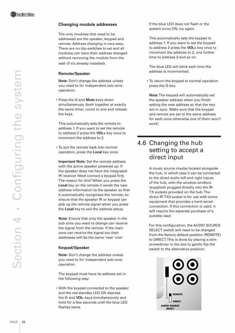
4.6 Changing the hub setting to accept a direct input
A music source maybe located alongside the hub, in which case it can be connected to the direct audio left and right inputs of the hub, with the window emitters (supplied) plugged directly into the IR-TX sockets provided on the hub. The direct IR-TX3 socket is for use with some equipment that provides a hard-wired connection. If this connection is used, it will require the separate purchase of a suitable lead.
For this confi guration, the AUDIO SOURCE SELECT switch will need to be changed from the factory default position (REMOTE) to DIRECT. This is done by placing a slim screwdriver in the slot to gently fl ip the switch to the alternative position:
REMOTE
DIRECT
AUDIO SOURCESELECT
PAGE 19
Sec
tio
n 5
• T
rou
ble
sho
oti
ng
5 Troubleshooting This chapter gives step-by-step troubleshooting procedures, with suggested solutions, to problems that may occur with the Systemline Modular System.
Golden rule
Always check cable connections
Speaker will not come out of
standby. The red standby indicator
blinks continuously
The amplifi er is short-circuited or thermally overloaded so the speaker has switched into self-protection mode.
The most likely cause of the fault is a short-circuited CAT5 speaker lead to the left passive speaker, either due to a damaged cable or crossed connections. Check the wiring and correct the fault with the system powered down. Power up the system again and check the speaker has reset and the fault is no longer present. Note: The speaker must be powered down and back up again to reset the self-protection feature.
Speaker will not come out of
standby. Red standby indicator
remains illuminated
This may be because the speaker and remote control or keypad have been set to two different infra-red addresses. Reset the infra-red addresses as described in Changing module addresses, page 18, and try again.
Speaker switches on, with the
blue indicator illuminated, but
there is no sound
If others zones are working this probably indicates a break or fault in the wiring between this zone and the audio distribution hub.
If no zones are working this probably indicates a fault in the wiring between the audio distribution hub and the line-level input module.
If the speaker has a connection for a local source, try connecting a local source to the speaker. If this works it indicates that the fault is in the wiring between the speaker and the main system.
Testing sub-zones
If a main zone works, but its sub-zone doesn’t work, this indicates a fault between the main zone and the sub-zone.
Sound breaks up and becomes
unstable at high volume settings
If all zones in the system are affected this is probably due to a faulty power supply, or a bad connection between the power supply and the audio distribution hub or power input module.
• Try an alternative power supply.
• Ensure that you are using a 130W power supply and not a 45W power supply at the audio distribution hub.
If only one zone is affected this is most likely to be due to inadequate power to the affected speaker.
• Check that the cable length to the affected speaker does not exceed 50m.
• Check that there is not a loose connection on the power supply connections to the affected speaker.
• Try connecting a local 45W power supply to the affected speaker.
• If the zone is a sub-zone, check that there is a local 45W power supply for the sub-zone, and that it is switched on and connected correctly.

PAGE 20
Sec
tio
n 5
• T
rou
ble
sho
oti
ng
Some zones sound too loud when
fi rst switched on
The start-up volume is confi gurable for each active speaker.
• Adjust the start-up volume of the zone as described in Setting bass, treble, and minimum/maximum volume levels, page 16.
PAGE 21
Sec
tio
n 6
• O
per
atin
g t
he
syst
em
6 Operating the systemThis chapter gives basic operating instructions for the Systemline Modular System.
Unless the system is going to be out of use for an extended period, it is designed to be powered up at all times. The standby current consumption is very low with a 6 zone system consuming around 15 Watts.
How the system is used will depend largely on how it is confi gured, particularly in relation to the source components. However the following guidelines should help:
The operational examples assume that speakers are IR enabled, that keypads are connected, and that local inputs are enabled. Please view accordingly, if any of these features are not specifi ed.
Turning a zone on
• Press the O key on either the keypad or remote.
The blue LED will illuminate on the speaker and also on the keypad if fi tted. The zone will always turn on at the pre-programmed turn on volume.
The blue LED indicates that the speaker’s input is listening to the system input. If audio is playing from a source you should now be able to hear it through the speakers.
To adjust the listening volume
• Use the VOL+ or VOL- keys on either the remote or keypad.
To select the local source
• If a local audio source is connected press the Local L key on the remote or O key on the keypad to toggle to the next input.
The green local LED will illuminate on the speaker and also on the keypad if fi tted.
Note: The volume will ramp down and the speaker will switch to the local and the
volume will be ramped up again to the previous volume.
You cannot select Local unless the speaker is on system – blue LED illuminated.
To switch back to system input
• Press the O key on the remote or the O key on the keypad.
The blue system LED will illuminate on the speaker and also on the keypad if fi tted.
To mute the system
• Press the Mute key on the remote. The volume will ramp down and the input status blue or green LED will fl ash to indicate that the speaker is muted. To release the mute press the VOL+ key on the remote or keypad.
Note: You cannot select Mute on the keypad.
To switch the zone off
• Press the O key on the remote or the O key on the keypad.
Controlling of the audio source is done using either the original equipment remote or else a learning remote containing the source codes. Point the remote at the IR receiver window on the speaker grille or the wall-mounted keypad.
Sub-zone operation – independent
operation
Ensure that the main zone is out of standby by pressing the O key on the keypad or remote within the main zone. Select either the System or Local main zone input depending on which source you want to feed through to the sub-zone.
Remember: If the main zone is off the sub-zone’s system input will be off.

PAGE 22
Sec
tio
n 6
• O
per
atin
g t
he
syst
emUsing the sub-zone’s keypad or remote turn the system ON by pressing the O key on the keypad or remote.
Controlling of the audio source in the sub-zone is done using either the original equipment remote or else a learning remote containing the source codes. Point the remote at the IR receiver window on the speaker grille or the wall-mounted keypad.


