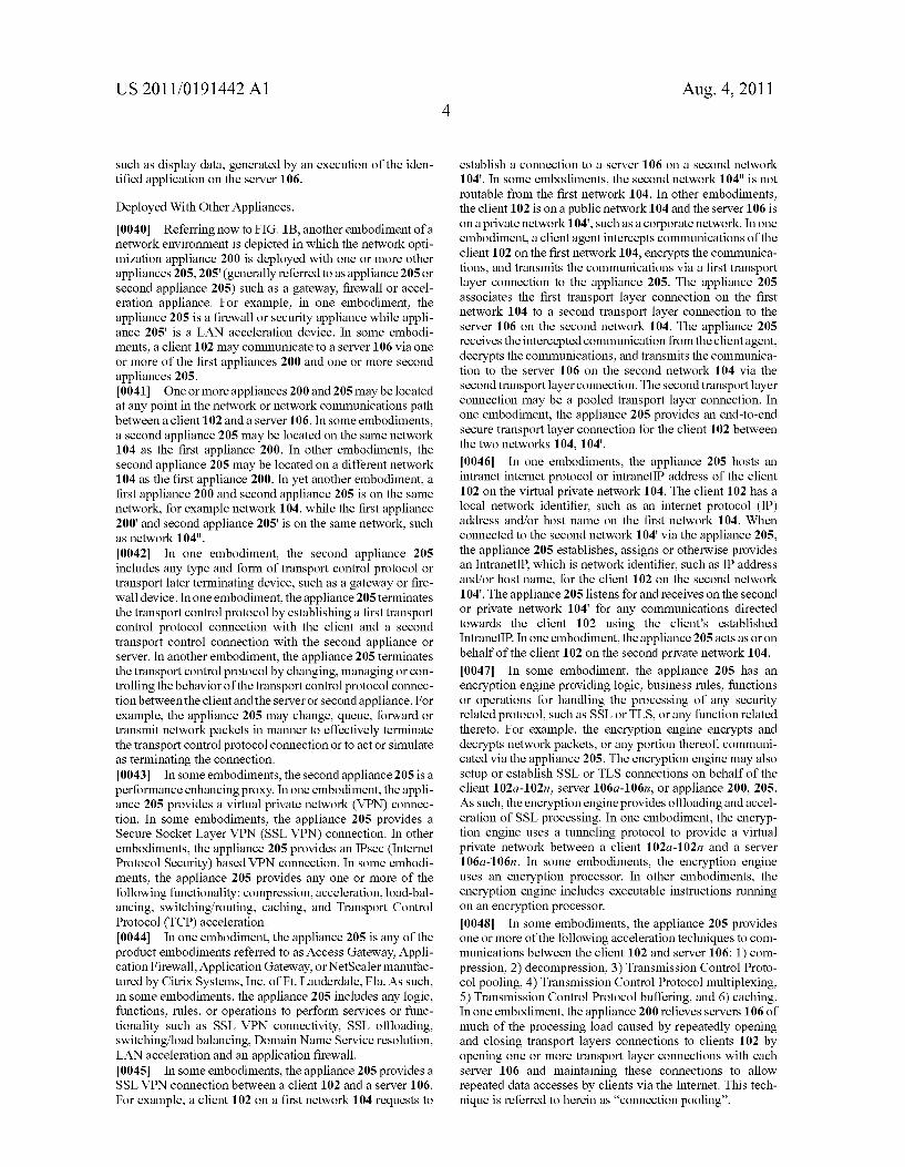
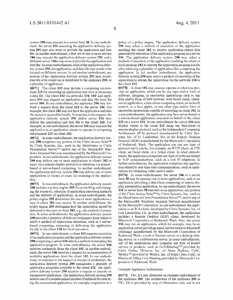
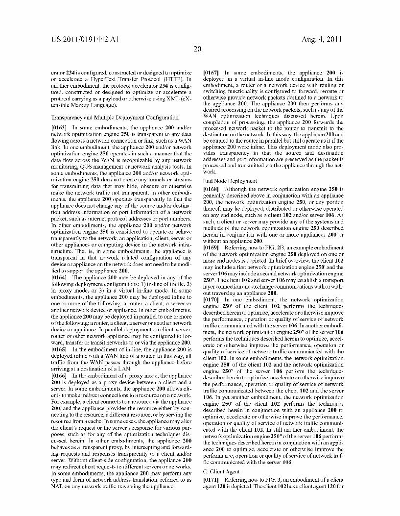
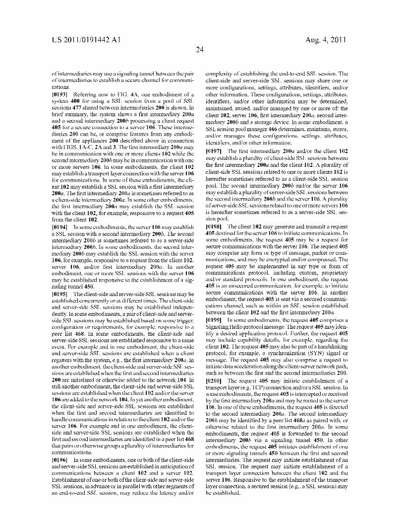
US 20110191442A1 (19) United States (12) Patent Application Publication (10) Pub. No.: US 2011/0191442 A1 Ovsiannikov (43) Pub. Date: Aug. 4, 201 1 (54) SYSTEMS AND METHODS OF USING SSL (52) US. Cl. ....................................... .. 709/218; 709/228 POOLS FOR WAN ACCELERATION (57) ABSTRACT (76) Inventor: Michael Ovsiannikov, San Mateo’ The present 1nvent1on 1s d1rected towards systems and meth ods for using a Secure Socket Layer (SSL) session from a pool of SSL sessions shared between intermediaries. The method includes receiving, by a ?rst intermediary, informa (21) App1_ NO; 12/696,333 tion on one or more SSL sessions ofa pool established by a second intermediary With a server. The ?rst intermediary can be in communication With one or more clients and the second (22) Filed: Jan- 29: 2010 intermediary can be in communication With one or more servers. The ?rst intermediary may receive a request from a client to establish an SSL session With the server. The ?rst intermediary can identify an SSL session from the pool of (51) Int. Cl. SSL sessions. The ?rst intermediary may establish the SSL G06F 15/16 (2006.01) session With the client responsive to the request. CA (US) Publication Classi?cation Client 102a Server 106a 20., 8 0 save 0 ‘1% Appliance Appliance Client 102b WAN WAN Optimization Optimization Serve’ 106D device) device 0 u’unu uuuu Client 102n Server 106n
Transcript
US 20110191442A1
(19) United States (12) Patent Application Publication (10) Pub. No.: US 2011/0191442 A1
Ovsiannikov (43) Pub. Date: Aug. 4, 201 1
(54) SYSTEMS AND METHODS OF USING SSL (52) US. Cl. ....................................... .. 709/218; 709/228
POOLS FOR WAN ACCELERATION (57) ABSTRACT
(76) Inventor: Michael Ovsiannikov, San Mateo’ The present 1nvent1on 1s d1rected towards systems and meth ods for using a Secure Socket Layer (SSL) session from a pool of SSL sessions shared between intermediaries. The method includes receiving, by a ?rst intermediary, informa
(21) App1_ NO; 12/696,333 tion on one or more SSL sessions ofa pool established by a second intermediary With a server. The ?rst intermediary can be in communication With one or more clients and the second
(22) Filed: Jan- 29: 2010 intermediary can be in communication With one or more servers. The ?rst intermediary may receive a request from a client to establish an SSL session With the server. The ?rst intermediary can identify an SSL session from the pool of
(51) Int. Cl. SSL sessions. The ?rst intermediary may establish the SSL G06F 15/16 (2006.01) session With the client responsive to the request.
Patent Application Publication Aug. 4, 2011 Sheet 9 0f 12 US 2011/0191442 A1
coo? 320m 0 o o 32 62mm 850w
U-UUU DUDE
noom EEvwEhEE 950mm 43. .QE
nmwv pm: Ema
wcow EEumEBQE “2E mwmw “mi .500.
new pwosaom
:NO 220:0 Novvcwzu
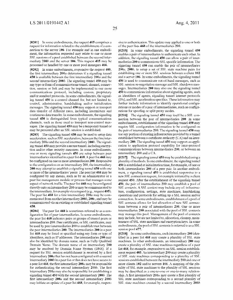
Patent Application Publication Aug. 4, 2011 Sheet 10 0f 12 US 2011/0191442 A1
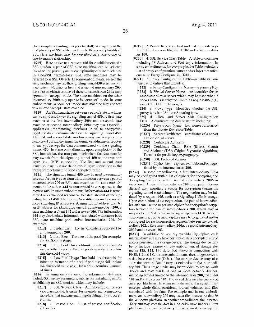
N? as 5322 mv GE
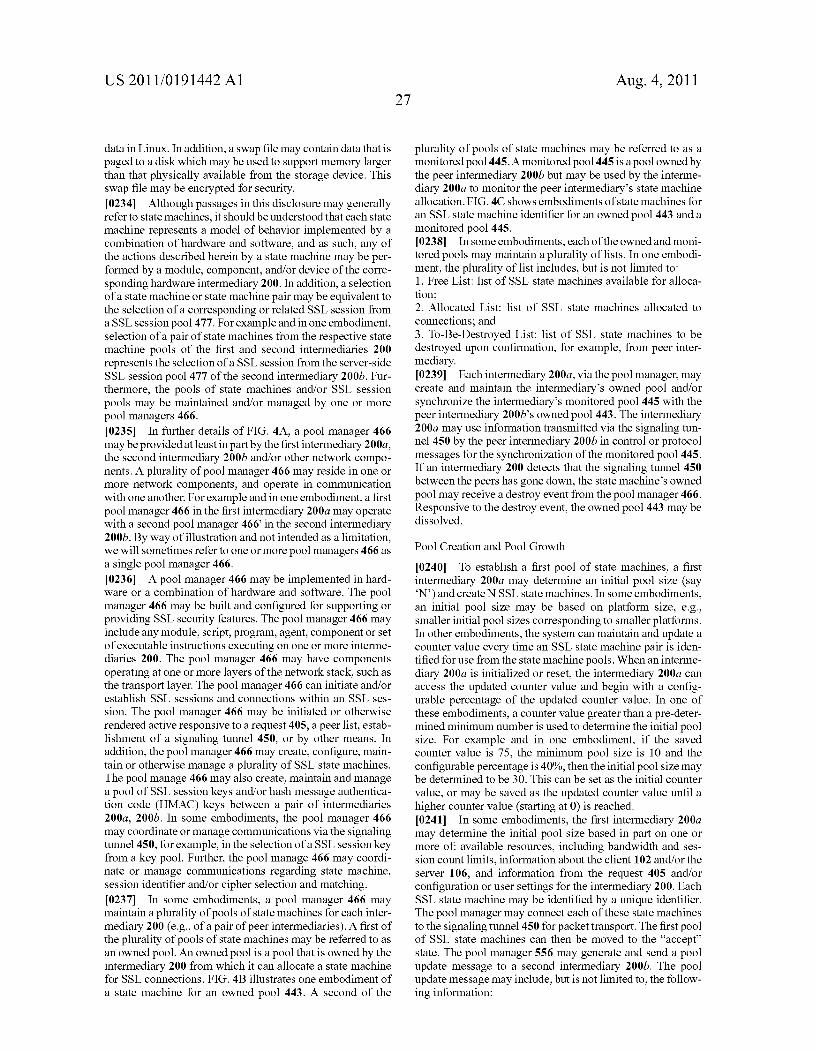
6cm x268
Q mam :com 265 ,
i Q >958 \ 26$ \ Q @8021: 60¢ xcccw
E“ as $9», mm“
33 855mm 68,3330
Boa 3:30 6m 2282 28m
Patent Application Publication Aug. 4, 2011 Sheet 11 0f 12 US 2011/0191442 A1
0% .0E E 22%: 35m ..mm .3 8“. 3E2; 29w
US 2011/0191442 A1
SYSTEMS AND METHODS OF USING SSL POOLS FOR WAN ACCELERATION
FIELD OF THE DISCLOSURE
[0001] The present application generally relates to data communication networks. In particular, the present applica tion relates to systems and methods of using Secure Socket Layer (SSL) pools for Wan acceleration.
BACKGROUND
[0002] End-to-end secure communications betWeen a cli ent and a server may be provided by an SSL session connec tion. The connection may be established across one or more
intermediaries, such as netWork appliances, betWeen the cli ent and the server. A single intermediary betWeen a client and a server may facilitate establishment of an SSL session con
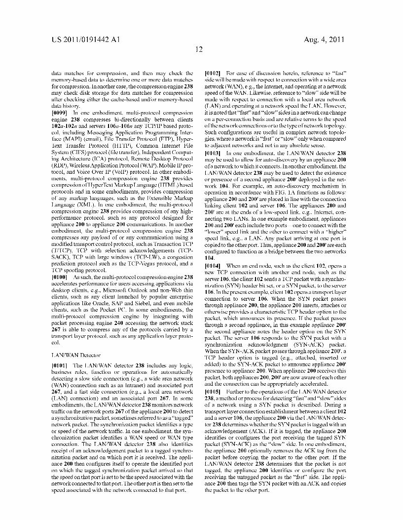
nection, providing shielding protection to the client via a virtual private netWork (VPN) for example. In some cases, there are multiple intermediaries, for example for providing data acceleration and other services betWeen tWo intermedi aries across one or more netWorks. The ?rst intermediary may be in communication With one or more clients While the second intermediary may be in communication With one or more servers.
BRIEF SUMMARY
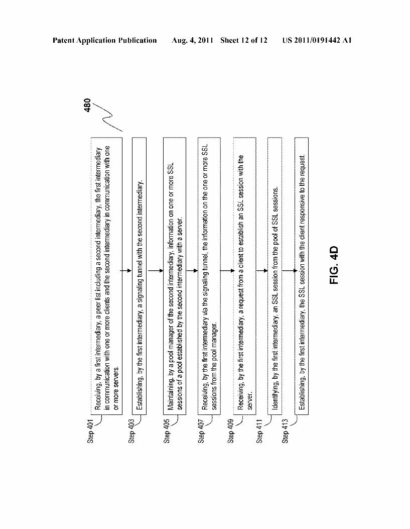
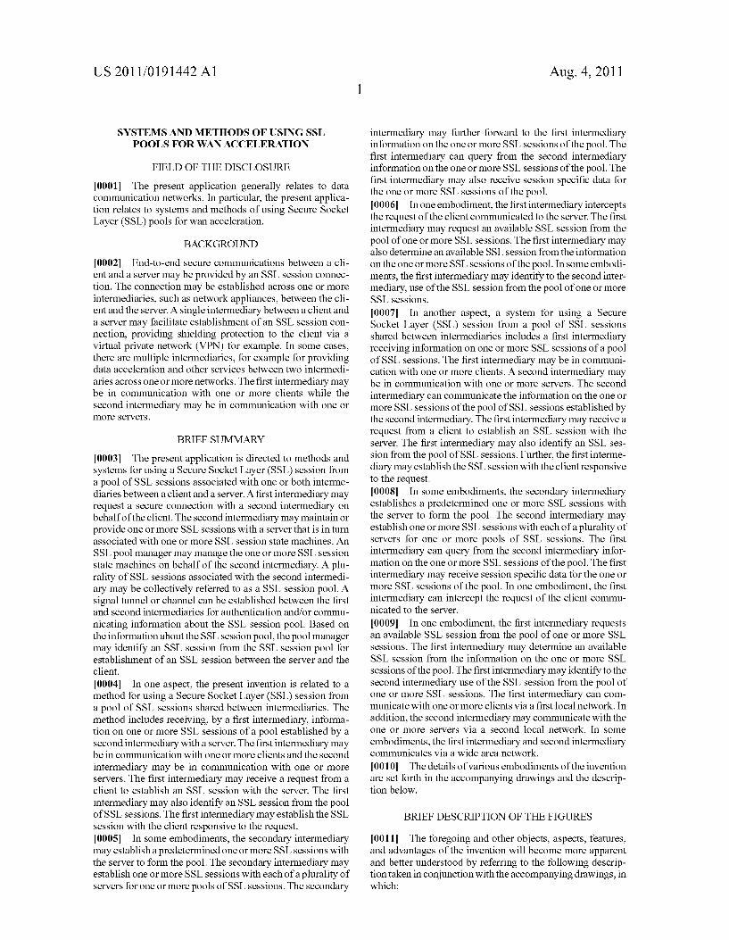
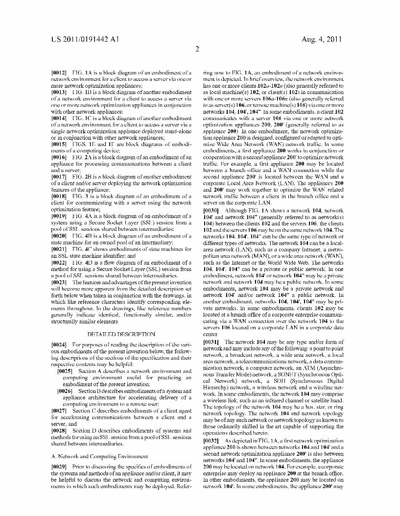
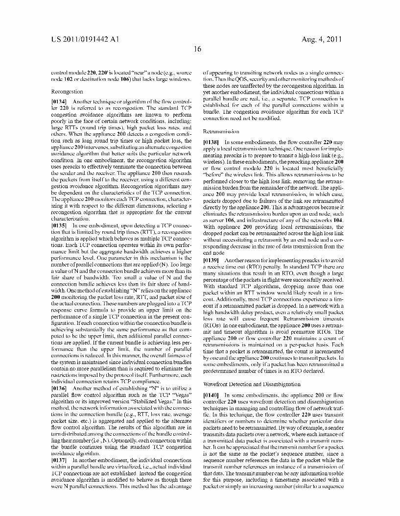
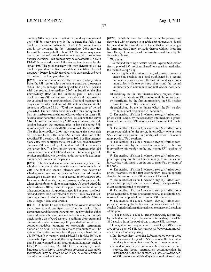
[0003] The present application is directed to methods and systems for using a Secure Socket Layer (SSL) session from a pool of SSL sessions associated With one or both interme diaries betWeen a client and a server. A ?rst intermediary may request a secure connection With a second intermediary on behalf of the client. The second intermediary may maintain or provide one or more SSL sessions With a server that is in turn associated With one or more SSL session state machines. An SSL pool manager may manage the one or more SSL session state machines on behalf of the second intermediary. A plu rality of SSL sessions associated With the second intermedi ary may be collectively referred to as a SSL session pool. A signal tunnel or channel can be established betWeen the ?rst and second intermediaries for authentication and/or commu nicating information about the SSL session pool. Based on the information about the SSL session pool, the pool manager may identify an SSL session from the SSL session pool for establishment of an SSL session betWeen the server and the client. [0004] In one aspect, the present invention is related to a method for using a Secure Socket Layer (SSL) session from a pool of SSL sessions shared betWeen intermediaries. The method includes receiving, by a ?rst intermediary, informa tion on one or more SSL sessions of a pool established by a second intermediary With a server. The ?rst intermediary may be in communication With one or more clients and the second intermediary may be in communication With one or more servers. The ?rst intermediary may receive a request from a client to establish an SSL session With the server. The ?rst intermediary may also identify an SSL session from the pool of SSL sessions. The ?rst intermediary may establish the SSL session With the client responsive to the request. [0005] In some embodiments, the secondary intermediary may establish a predetermined one or more SSL sessions With the server to form the pool. The secondary intermediary may establish one or more SSL sessions With each of a plurality of servers for one or more pools of SSL sessions. The secondary
Aug. 4, 2011
intermediary may further forWard to the ?rst intermediary information on the one or more SSL sessions of the pool. The ?rst intermediary can query from the second intermediary information on the one or more SSL sessions of the pool. The ?rst intermediary may also receive session speci?c data for the one or more SSL sessions of the pool.
[0006] In one embodiment, the ?rst intermediary intercepts the request of the client communicated to the server. The ?rst intermediary may request an available SSL session from the pool of one or more SSL sessions. The ?rst intermediary may also determine an available SSL session from the information on the one or more SSL sessions of the pool. In some embodi ments, the ?rst intermediary may identify to the second inter mediary, use of the SSL session from the pool of one or more SSL sessions. [0007] In another aspect, a system for using a Secure Socket Layer (SSL) session from a pool of SSL sessions shared betWeen intermediaries includes a ?rst intermediary receiving information on one or more SSL sessions of a pool of SSL sessions. The ?rst intermediary may be in communi cation With one or more clients. A second intermediary may be in communication With one or more servers. The second
intermediary can communicate the information on the one or more SSL sessions of the pool of SSL sessions established by the second intermediary. The ?rst intermediary may receive a request from a client to establish an SSL session With the server. The ?rst intermediary may also identify an SSL ses sion from the pool of SSL sessions. Further, the ?rst interme diary may establish the SSL session With the client responsive to the request. [0008] In some embodiments, the secondary intermediary establishes a predetermined one or more SSL sessions With the server to form the pool. The second intermediary may establish one or more SSL sessions With each of a plurality of servers for one or more pools of SSL sessions. The ?rst intermediary can query from the second intermediary infor mation on the one or more SSL sessions of the pool. The ?rst intermediary may receive session speci?c data for the one or more SSL sessions of the pool. In one embodiment, the ?rst intermediary can intercept the request of the client commu nicated to the server.
[0009] In one embodiment, the ?rst intermediary requests an available SSL session from the pool of one or more SSL sessions. The ?rst intermediary may determine an available SSL session from the information on the one or more SSL sessions of the pool. The ?rst intermediary may identify to the second intermediary use of the SSL session from the pool of one or more SSL sessions. The ?rst intermediary can com municate With one or more clients via a ?rst local netWork. In addition, the second intermediary may communicate With the one or more servers via a second local netWork. In some
embodiments, the ?rst intermediary and second intermediary communicates via a Wide area netWork.
[0010] The details of various embodiments of the invention are set forth in the accompanying draWings and the descrip tion beloW.
BRIEF DESCRIPTION OF THE FIGURES
[0011] The foregoing and other objects, aspects, features, and advantages of the invention Will become more apparent and better understood by referring to the folloWing descrip tion taken in conjunction With the accompanying draWings, in Which:
US 2011/0191442 A1
[0012] FIG. 1A is a block diagram of an embodiment ofa network environment for a client to access a server via one or
more netWork optimization appliances; [0013] FIG. 1B is a block diagram of another embodiment of a netWork environment for a client to access a server via
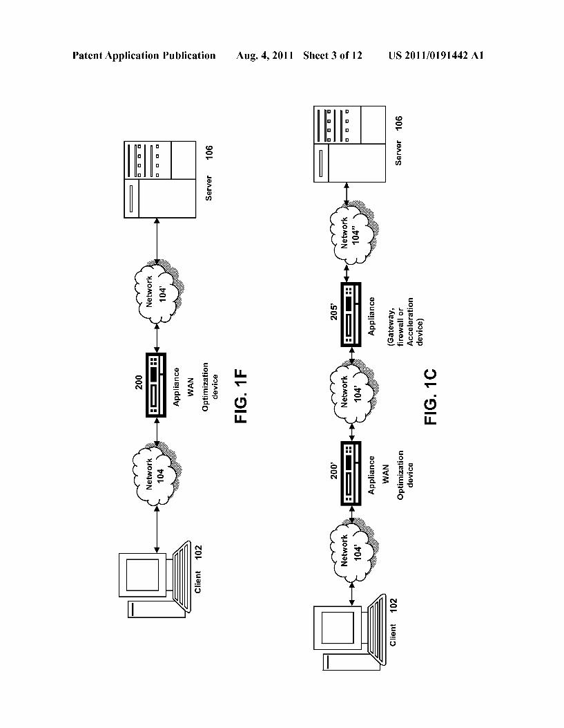
one or more netWork optimiZation appliances in conjunction With other netWork appliances; [0014] FIG. 1C is a block diagram of another embodiment of a netWork environment for a client to access a server via a
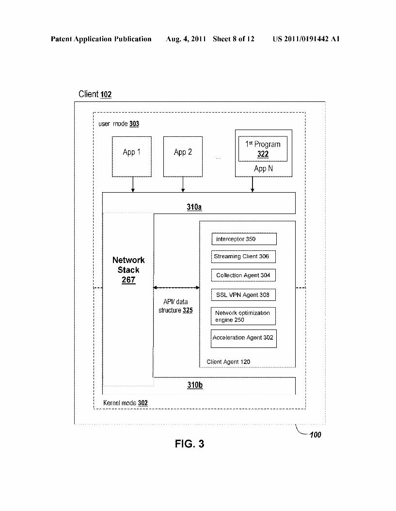
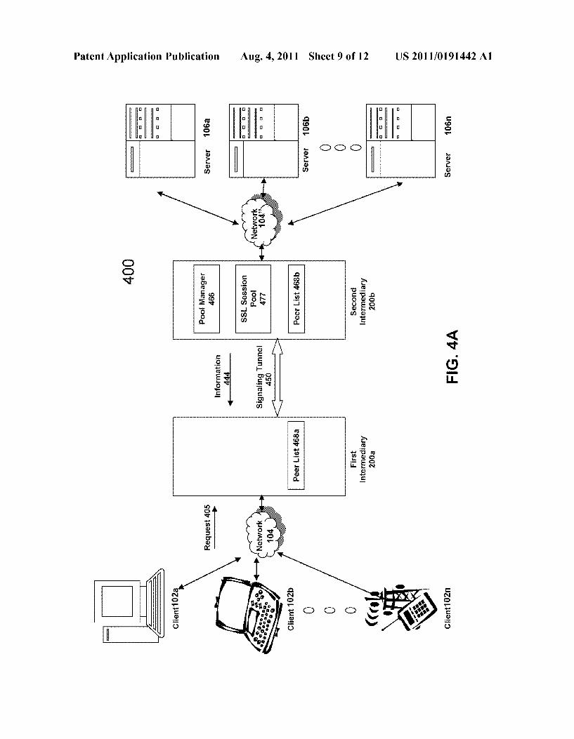
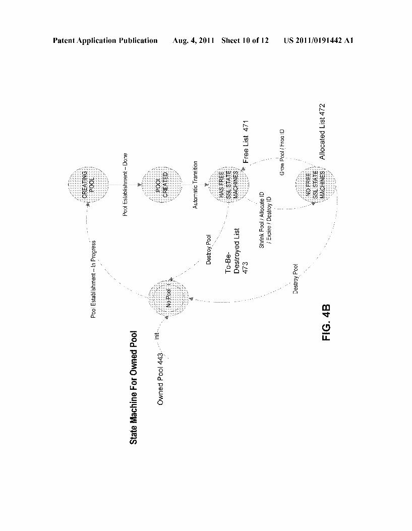
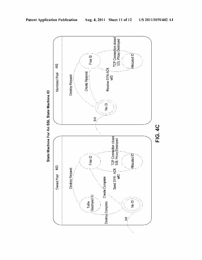
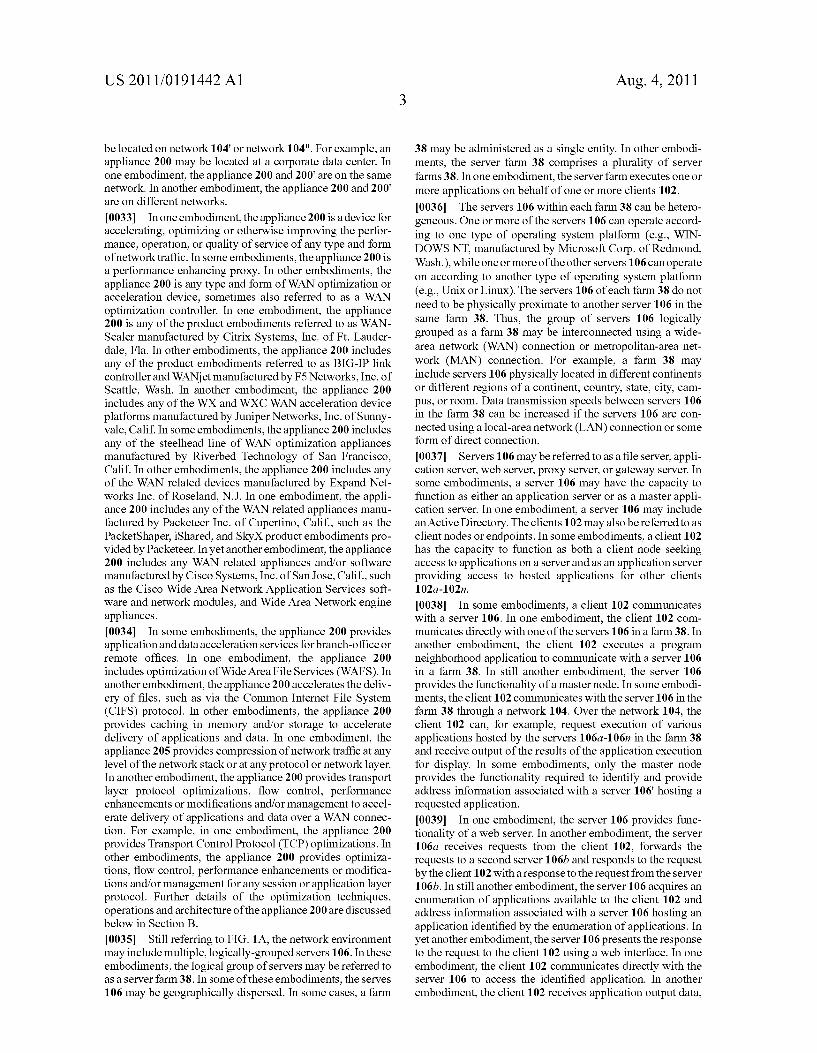
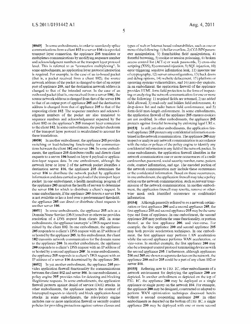
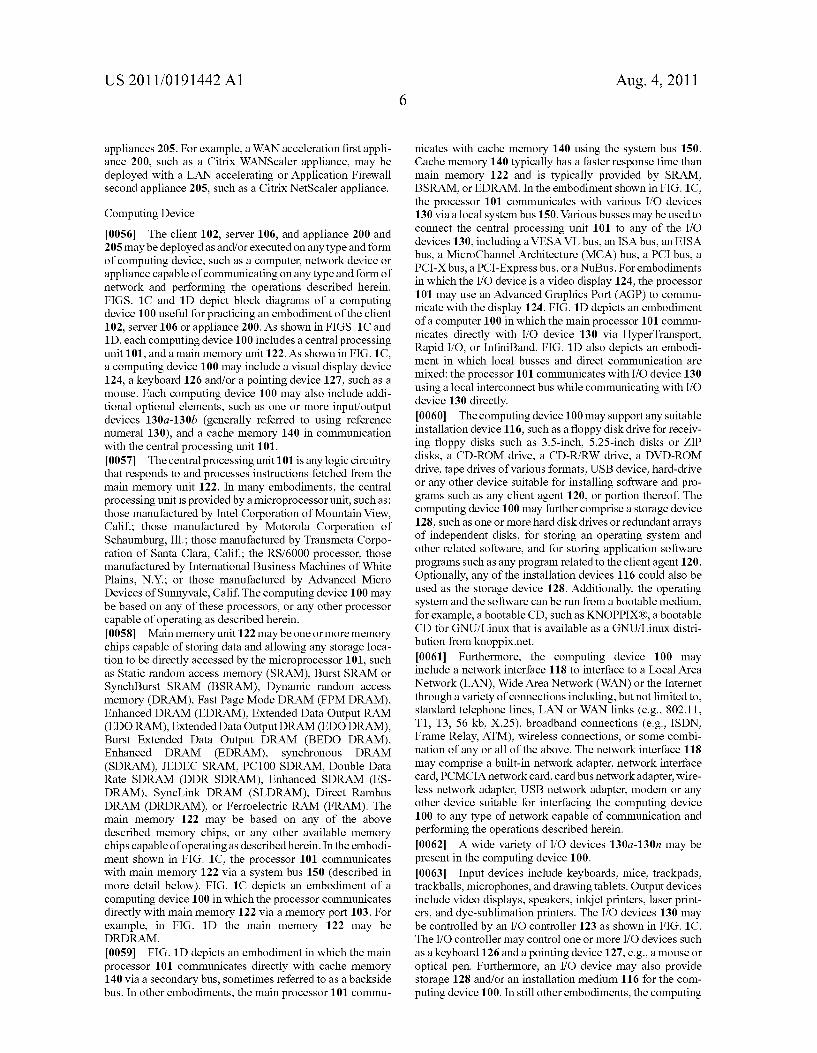
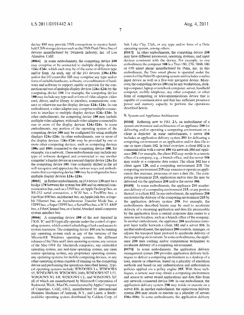
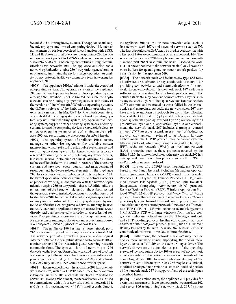
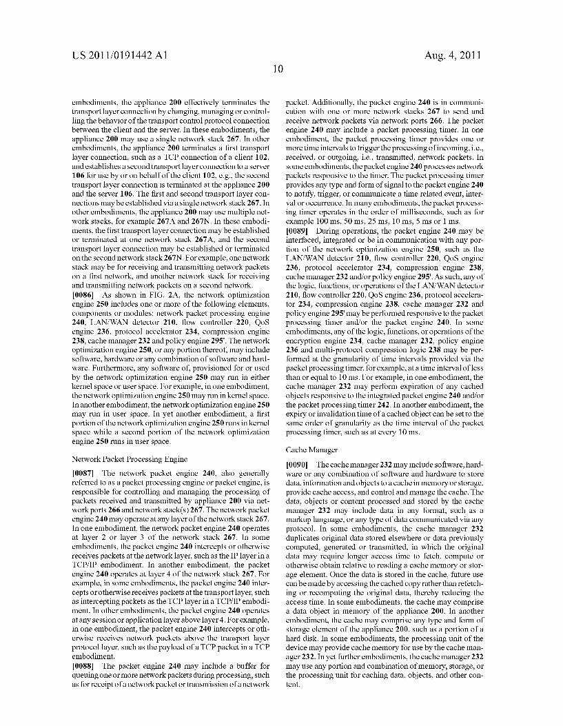
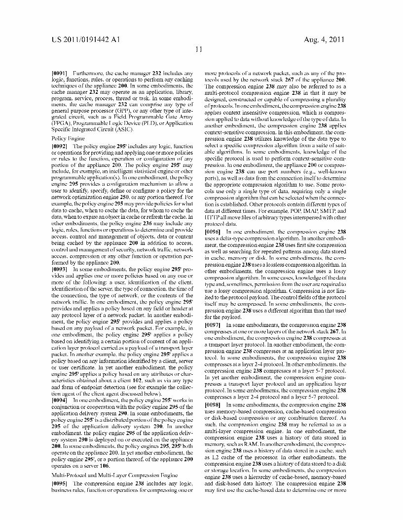
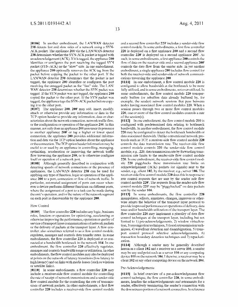
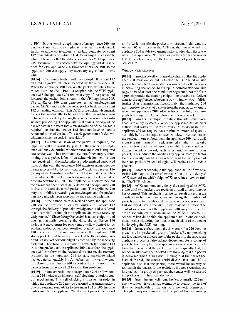
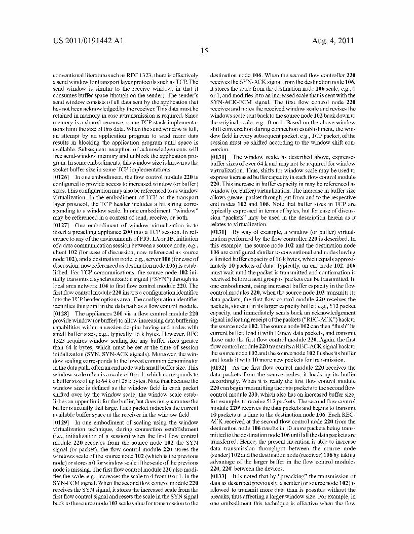
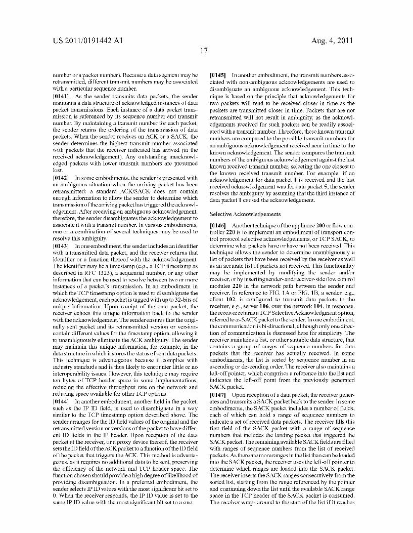
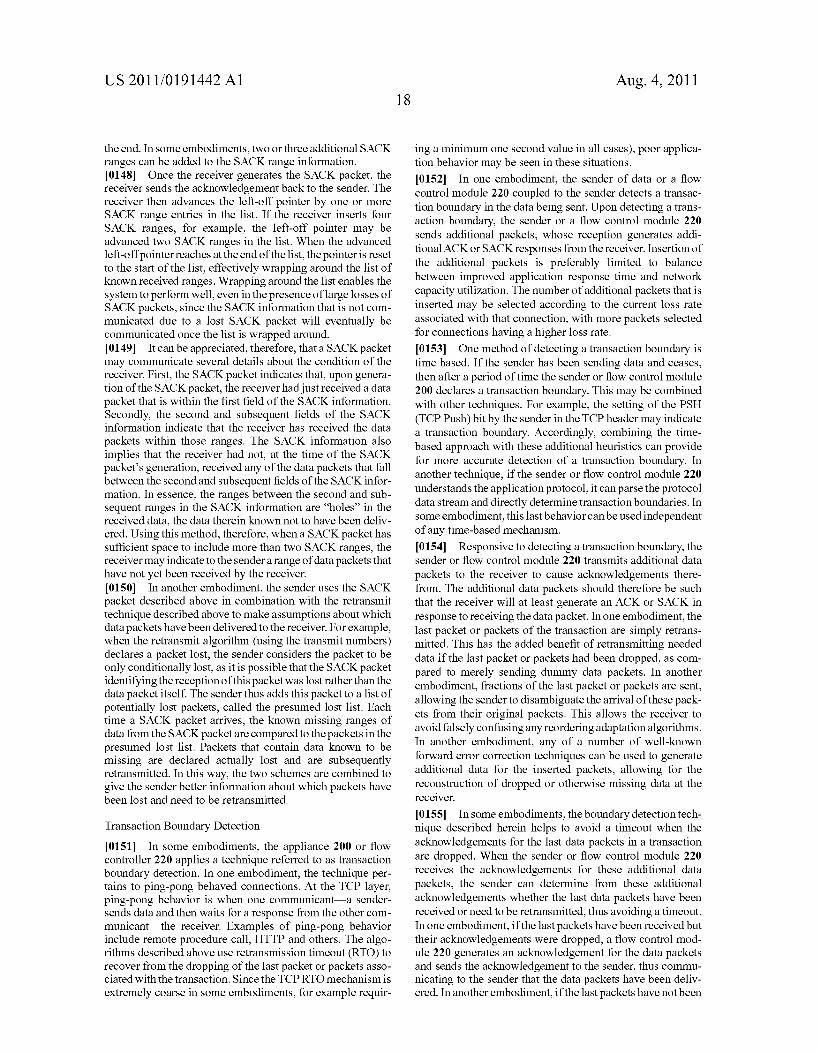
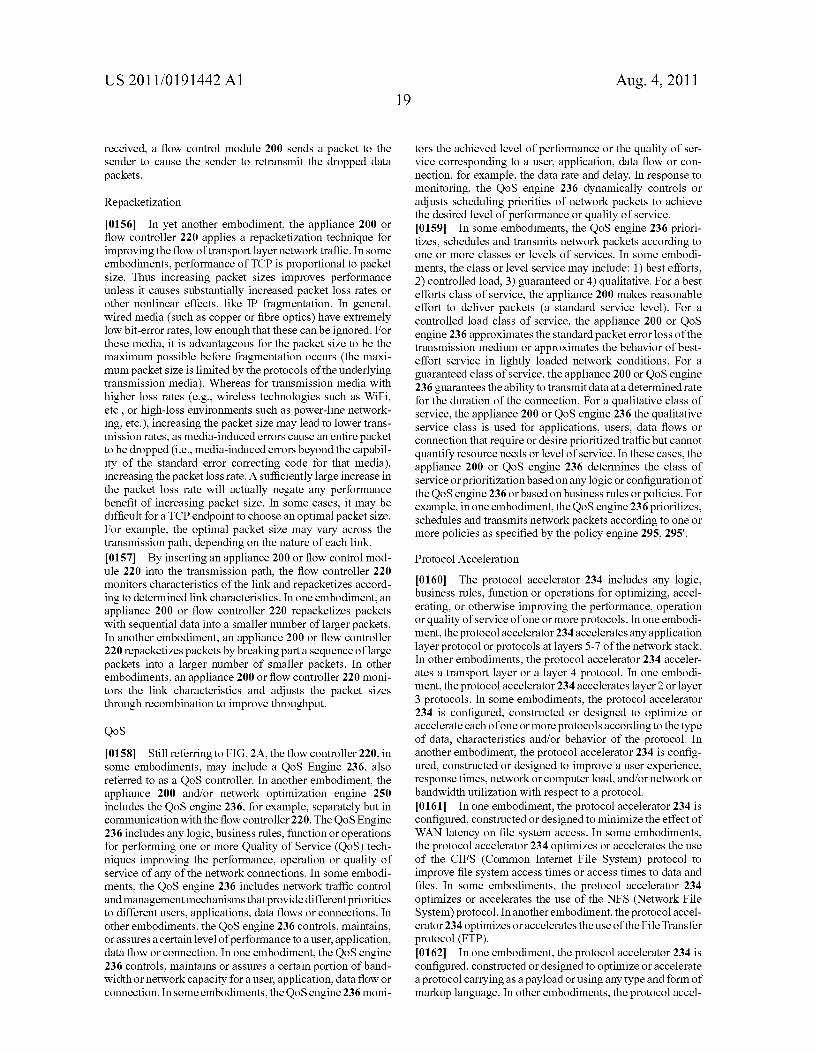
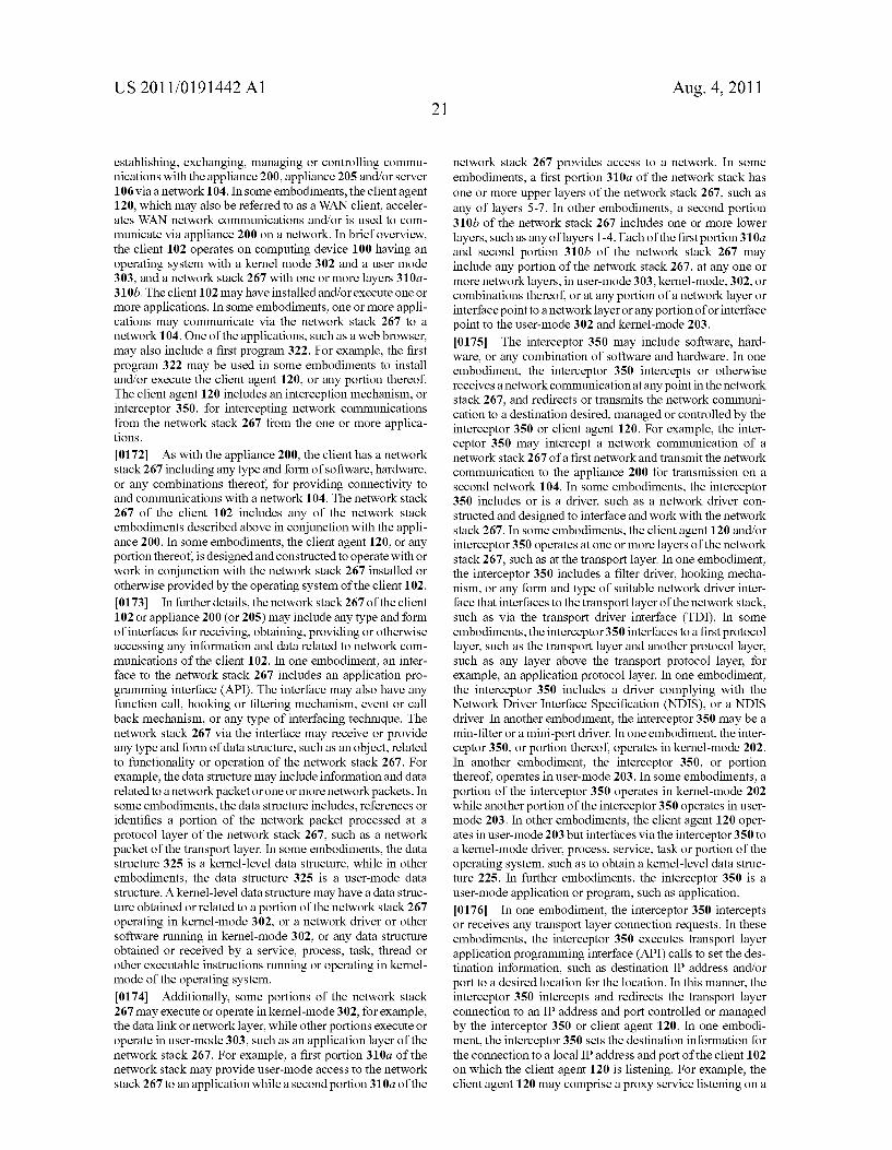
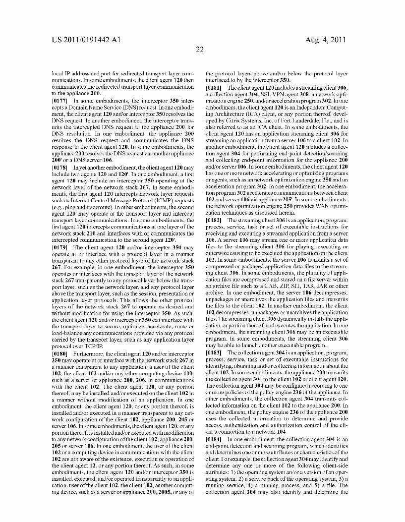
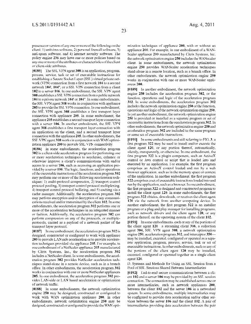
single netWork optimiZation appliance deployed stand-alone or in conjunction With other netWork appliances; [0015] FIGS. 1E and 1E are block diagrams of embodi ments of a computing device; [0016] FIG. 2A is a block diagram ofan embodiment ofan appliance for processing communications betWeen a client and a server; [0017] FIG. 2B is a block diagram of another embodiment of a client and/or server deploying the netWork optimiZation features of the appliance; [0018] FIG. 3 is a block diagram of an embodiment of a client for communicating With a server using the netWork optimiZation feature; [0019] FIG. 4A is a block diagram of an embodiment ofa system using a Secure Socket Layer (SSL) session from a pool of SSL sessions shared betWeen intermediaries; [0020] FIG. 4B is a block diagram of an embodiment of a state machine for an oWned pool of an intermediary; [0021] FIG. 4C shoWs embodiments of state machines for an SSL state machine identi?er; and [0022] FIG. 4D is a How diagram of an embodiment of a method for using a Secure Socket Layer (SSL) session from a pool of SSL sessions shared betWeen intermediaries. [0023] The features and advantages of the present invention Will become more apparent from the detailed description set forth beloW When taken in conjunction With the draWings, in Which like reference characters identify corresponding ele ments throughout. In the draWings, like reference numbers generally indicate identical, functionally similar, and/or structurally similar elements.
DETAILED DESCRIPTION
[0024] For purposes of reading the description of the vari ous embodiments of the present invention beloW, the folloW ing descriptions of the sections of the speci?cation and their respective contents may be helpful:
[0025] Section A describes a netWork environment and computing environment useful for practicing an embodiment of the present invention;
[0026] Section B describes embodiments of a system and appliance architecture for accelerating delivery of a computing environment to a remote user;
[0027] Section C describes embodiments of a client agent for accelerating communications betWeen a client and a server; and [0028] Section D describes embodiments of systems and methods forusing an SSL session from a pool of SSL sessions shared betWeen intermediaries.
A. NetWork and Computing Environment
[0029] Prior to discussing the speci?cs of embodiments of the systems and methods of an appliance and/or client, it may be helpful to discuss the netWork and computing environ ments in Which such embodiments may be deployed. Refer
Aug. 4, 2011
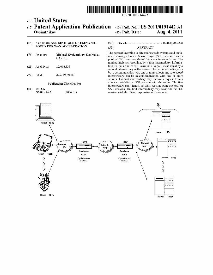
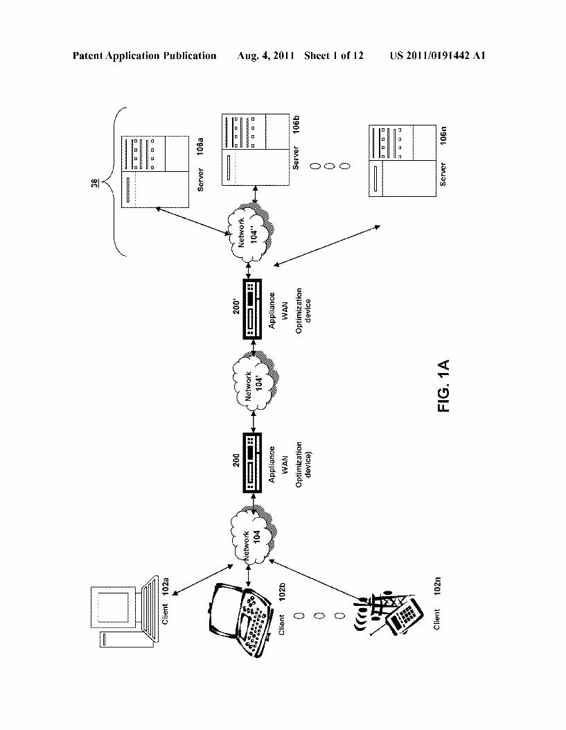
ring noW to FIG. 1A, an embodiment of a netWork environ ment is depicted. In brief overvieW, the netWork environment has one or more clients 102a-102n (also generally referred to as local machine(s) 102, or client(s) 102) in communication With one or more servers 106a-106n (also generally referred to as server(s) 106, or remote machine(s) 106) via one or more netWorks 104, 104', 104". In some embodiments, a client 102 communicates With a server 106 via one or more netWork
optimiZation appliances 200, 200' (generally referred to as appliance 200). In one embodiment, the netWork optimiZa tion appliance 200 is designed, con?gured or adapted to opti miZe Wide Area NetWork (WAN) netWork traf?c. In some embodiments, a ?rst appliance 200 Works in conjunction or cooperation With a second appliance 200' to optimiZe netWork traf?c. For example, a ?rst appliance 200 may be located betWeen a branch of?ce and a WAN connection While the second appliance 200' is located betWeen the WAN and a corporate Local Area NetWork (LAN). The appliances 200 and 200' may Work together to optimiZe the WAN related netWork tra?ic betWeen a client in the branch of?ce and a server on the corporate LAN.
[0030] Although FIG. 1A shoWs a netWork 104, netWork 104' and netWork 104" (generally referred to as netWork(s) 104) betWeen the clients 102 and the servers 106, the clients 102 and the servers 106 may be on the same netWork 104. The netWorks 104, 104', 104" can be the same type of netWork or different types of netWorks. The netWork 104 can be a local area netWork (LAN), such as a company Intranet, a metro politan area netWork (MAN), or a Wide area netWork (WAN), such as the Internet or the World Wide Web. The netWorks 104, 104', 104" can be a private or public netWork. In one embodiment, netWork 104' or netWork 104" may be a private netWork and netWork 104 may be a public netWork. In some embodiments, netWork 104 may be a private netWork and netWork 104' and/or netWork 104" a public netWork. In another embodiment, netWorks 104, 104', 104" may be pri vate netWorks. In some embodiments, clients 102 may be located at a branch of?ce of a corporate enterprise communi cating via a WAN connection over the netWork 104 to the servers 106 located on a corporate LAN in a corporate data center.
[0031] The netWork 104 may be any type and/or form of netWork and may include any of the folloWing: a point to point netWork, a broadcast netWork, a Wide area netWork, a local area netWork, a telecommunications netWork, a data commu nication netWork, a computer netWork, an ATM (Asynchro nous Transfer Mode) netWork, a SONET (Synchronous Opti cal NetWork) netWork, a SDH (Synchronous Digital Hierarchy) netWork, a Wireless netWork and a Wireline net Work. In some embodiments, the netWork 104 may comprise a Wireless link, such as an infrared channel or satellite band. The topology of the netWork 104 may be a bus, star, or ring netWork topology. The netWork 104 and netWork topology may be of any such netWork or netWork topology as knoWn to those ordinarily skilled in the art capable of supporting the operations described herein. [0032] As depicted in FIG. 1A, a ?rst netWork optimiZation appliance 200 is shoWn betWeen netWorks 104 and 104' and a second netWork optimiZation appliance 200' is also betWeen netWorks 104' and 104". In some embodiments, the appliance 200 may be located on netWork 104. For example, a corporate enterprise may deploy an appliance 200 at the branch of?ce. In other embodiments, the appliance 200 may be located on netWork 104'. In some embodiments, the appliance 200' may
US 2011/0191442 A1
be located on network 104' or network 104". For example, an appliance 200 may be located at a corporate data center. In one embodiment, the appliance 200 and 200' are on the same network. In another embodiment, the appliance 200 and 200' are on different networks.
[0033] In one embodiment, the appliance 200 is a device for accelerating, optimizing or otherwise improving the perfor mance, operation, or quality of service of any type and form of network traf?c. In some embodiments, the appliance 200 is a performance enhancing proxy. In other embodiments, the appliance 200 is any type and form of WAN optimization or acceleration device, sometimes also referred to as a WAN optimization controller. In one embodiment, the appliance 200 is any of the product embodiments referred to as WAN Scaler manufactured by Citrix Systems, Inc. of Ft. Lauder dale, Fla. In other embodiments, the appliance 200 includes any of the product embodiments referred to as BIG-IP link controller and WANj et manufactured by F5 Networks, Inc. of Seattle, Wash. In another embodiment, the appliance 200 includes any of the WX and WXC WAN acceleration device platforms manufactured by Juniper Networks, Inc. of Sunny vale, Calif. In some embodiments, the appliance 200 includes any of the steelhead line of WAN optimization appliances manufactured by Riverbed Technology of San Francisco, Calif. In other embodiments, the appliance 200 includes any of the WAN related devices manufactured by Expand Net works Inc. of Roseland, N]. In one embodiment, the appli ance 200 includes any of the WAN related appliances manu factured by Packeteer Inc. of Cupertino, Calif., such as the PacketShaper, iShared, and SkyX product embodiments pro vided by Packeteer. In yet another embodiment, the appliance 200 includes any WAN related appliances and/or software manufactured by Cisco Systems, Inc. of San Jose, Calif., such as the Cisco Wide Area Network Application Services soft ware and network modules, and Wide Area Network engine appliances. [0034] In some embodiments, the appliance 200 provides application and data acceleration services for branch-of?ce or remote of?ces. In one embodiment, the appliance 200 includes optimization of Wide Area File Services (WAFS). In another embodiment, the appliance 200 accelerates the deliv ery of ?les, such as via the Common Internet File System (CIFS) protocol. In other embodiments, the appliance 200 provides caching in memory and/or storage to accelerate delivery of applications and data. In one embodiment, the appliance 205 provides compression of network traf?c at any level of the network stack or at any protocol or network layer. In another embodiment, the appliance 200 provides transport layer protocol optimizations, ?ow control, performance enhancements or modi?cations and/ or management to accel erate delivery of applications and data over a WAN connec tion. For example, in one embodiment, the appliance 200 provides Transport Control Protocol (TCP) optimizations. In other embodiments, the appliance 200 provides optimiza tions, ?ow control, performance enhancements or modi?ca tions and/or management for any session or application layer protocol. Further details of the optimization techniques, operations and architecture of the appliance 200 are discussed below in Section B.
[0035] Still referring to FIG. 1A, the network environment may include multiple, logically-grouped servers 106. In these embodiments, the logical group of servers may be referred to as a server farm 38. In some of these embodiments, the serves 106 may be geographically dispersed. In some cases, a farm
Aug. 4, 2011
38 may be administered as a single entity. In other embodi ments, the server farm 38 comprises a plurality of server farms 38. In one embodiment, the server farm executes one or
more applications on behalf of one or more clients 102.
[0036] The servers 106 within each farm 38 can be hetero geneous. One or more of the servers 106 can operate accord
ing to one type of operating system platform (e.g., WIN DOWS NT, manufactured by Microsoft Corp. of Redmond, Wash.), while one or more of the other servers 106 can operate on according to another type of operating system platform (e.g., Unix or Linux). The servers 106 of each farm 38 do not need to be physically proximate to another server 106 in the same farm 38. Thus, the group of servers 106 logically grouped as a farm 38 may be interconnected using a wide area network (WAN) connection or metropolitan-area net work (MAN) connection. For example, a farm 38 may include servers 106 physically located in different continents or different regions of a continent, country, state, city, cam pus, or room. Data transmission speeds between servers 106 in the farm 38 can be increased if the servers 106 are con nected using a local-area network (LAN) connection or some form of direct connection.
[0037] Servers 106 may be referred to as a ?le server, appli cation server, web server, proxy server, or gateway server. In some embodiments, a server 106 may have the capacity to function as either an application server or as a master appli
cation server. In one embodiment, a server 106 may include anActive Directory. The clients 102 may also be referred to as client nodes or endpoints. In some embodiments, a client 102 has the capacity to function as both a client node seeking access to applications on a server and as an application server
providing access to hosted applications for other clients 10211-10211.
[0038] In some embodiments, a client 102 communicates with a server 106. In one embodiment, the client 102 com municates directly with one of the servers 106 in a farm 38. In another embodiment, the client 102 executes a program neighborhood application to communicate with a server 106 in a farm 38. In still another embodiment, the server 106 provides the functionality of a master node. In some embodi ments, the client 102 communicates with the server 106 in the farm 38 through a network 104. Over the network 104, the client 102 can, for example, request execution of various applications hosted by the servers 106a-106n in the farm 38 and receive output of the results of the application execution for display. In some embodiments, only the master node provides the functionality required to identify and provide address information associated with a server 106' hosting a requested application. [0039] In one embodiment, the server 106 provides func tionality of a web server. In another embodiment, the server 106a receives requests from the client 102, forwards the requests to a second server 1061) and responds to the request by the client 102 with a response to the request from the server 1061). In still another embodiment, the server 106 acquires an enumeration of applications available to the client 102 and address information associated with a server 106 hosting an application identi?ed by the enumeration of applications. In yet another embodiment, the server 106 presents the response to the request to the client 102 using a web interface. In one embodiment, the client 102 communicates directly with the server 106 to access the identi?ed application. In another embodiment, the client 102 receives application output data,
US 2011/0191442 A1
such as display data, generated by an execution of the iden ti?ed application on the server 106.
Deployed With Other Appliances.
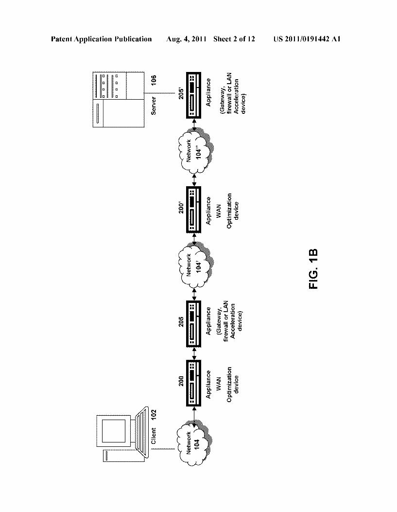
[0040] Referring noW to FIG. 1B, another embodiment of a netWork environment is depicted in Which the netWork opti miZation appliance 200 is deployed With one or more other appliances 205, 205' (generally referred to as appliance 205 or second appliance 205) such as a gateWay, ?reWall or accel eration appliance. For example, in one embodiment, the appliance 205 is a ?reWall or security appliance While appli ance 205' is a LAN acceleration device. In some embodi ments, a client 102 may communicate to a server 106 via one or more of the ?rst appliances 200 and one or more second appliances 205. [0041] One or more appliances 200 and 205 may be located at any point in the netWork or netWork communications path betWeen a client 102 and a server 106. In some embodiments, a second appliance 205 may be located on the same netWork 104 as the ?rst appliance 200. In other embodiments, the second appliance 205 may be located on a different netWork 104 as the ?rst appliance 200. In yet another embodiment, a ?rst appliance 200 and second appliance 205 is on the same network, for example netWork 104, While the ?rst appliance 200' and second appliance 205' is on the same netWork, such as netWork 104".
[0042] In one embodiment, the second appliance 205 includes any type and form of transport control protocol or transport later terminating device, such as a gateWay or ?re Wall device. In one embodiment, the appliance 205 terminates the transport control protocol by establishing a ?rst transport control protocol connection With the client and a second transport control connection With the second appliance or server. In another embodiment, the appliance 205 terminates the transport control protocol by changing, managing or con trolling the behavior of the transport control protocol connec tion betWeen the client and the server or second appliance. For example, the appliance 205 may change, queue, forWard or transmit netWork packets in manner to effectively terminate the transport control protocol connection or to act or simulate as terminating the connection. [0043] In some embodiments, the second appliance 205 is a performance enhancing proxy. In one embodiment, the appli ance 205 provides a virtual private netWork (VPN) connec tion. In some embodiments, the appliance 205 provides a Secure Socket Layer VPN (SSL VPN) connection. In other embodiments, the appliance 205 provides an IPsec (Internet Protocol Security) based VPN connection. In some embodi ments, the appliance 205 provides any one or more of the folloWing functionality: compression, acceleration, load-bal ancing, switching/routing, caching, and Transport Control Protocol (TCP) acceleration. [0044] In one embodiment, the appliance 205 is any of the product embodiments referred to as Access GateWay, Appli cation FireWall, Application GateWay, or NetScaler manufac tured by Citrix Systems, Inc. of Ft. Lauderdale, Fla. As such, in some embodiments, the appliance 205 includes any logic, functions, rules, or operations to perform services or func tionality such as SSL VPN connectivity, SSL of?oading, sWitching/load balancing, Domain Name Service resolution, LAN acceleration and an application ?reWall. [0045] In some embodiments, the appliance 205 provides a SSL VPN connection betWeen a client 102 and a server 106. For example, a client 102 on a ?rst netWork 104 requests to
Aug. 4, 2011
establish a connection to a server 106 on a second netWork
104'. In some embodiments, the second netWork 104" is not routable from the ?rst netWork 104. In other embodiments, the client 102 is on a public netWork 104 and the server 106 is on a private netWork 104', such as a corporate network. In one embodiment, a client agent intercepts communications of the client 102 on the ?rst netWork 104, encrypts the communica tions, and transmits the communications via a ?rst transport layer connection to the appliance 205. The appliance 205 associates the ?rst transport layer connection on the ?rst netWork 104 to a second transport layer connection to the server 106 on the second netWork 104. The appliance 205 receives the intercepted communication from the client agent, decrypts the communications, and transmits the communica tion to the server 106 on the second netWork 104 via the second transport layer connection. The second transport layer connection may be a pooled transport layer connection. In one embodiment, the appliance 205 provides an end-to-end secure transport layer connection for the client 102 betWeen the tWo netWorks 104, 104'.
[0046] In one embodiments, the appliance 205 hosts an intranet internet protocol or intranetIP address of the client 102 on the virtual private netWork 104. The client 102 has a local netWork identi?er, such as an internet protocol (IP) address and/or host name on the ?rst netWork 104. When connected to the second netWork 104' via the appliance 205, the appliance 205 establishes, assigns or otherWise provides an IntranetIP, Which is netWork identi?er, such as IP address and/or host name, for the client 102 on the second netWork 104'. The appliance 205 listens for and receives on the second or private netWork 104' for any communications directed toWards the client 102 using the client’s established IntranetIP. In one embodiment, the appliance 205 acts as or on behalf of the client 102 on the second private netWork 104.
[0047] In some embodiment, the appliance 205 has an encryption engine providing logic, business rules, functions or operations for handling the processing of any security related protocol, such as SSL or TLS, or any function related thereto. For example, the encryption engine encrypts and decrypts netWork packets, or any portion thereof, communi cated via the appliance 205. The encryption engine may also setup or establish SSL or TLS connections on behalf of the client 102a-102n, server 106a-106n, or appliance 200, 205. As such, the encryption engine provides of?oading and accel eration of SSL processing. In one embodiment, the encryp tion engine uses a tunneling protocol to provide a virtual private netWork betWeen a client 102a-102n and a server 106a-106n. In some embodiments, the encryption engine uses an encryption processor. In other embodiments, the encryption engine includes executable instructions running on an encryption processor.
[0048] In some embodiments, the appliance 205 provides one or more of the folloWing acceleration techniques to com munications betWeen the client 102 and server 106: 1) com pression, 2) decompression, 3) Transmission Control Proto col pooling, 4) Transmission Control Protocol multiplexing, 5) Transmission Control Protocol buffering, and 6) caching. In one embodiment, the appliance 200 relieves servers 106 of much of the processing load caused by repeatedly opening and closing transport layers connections to clients 102 by opening one or more transport layer connections With each server 106 and maintaining these connections to alloW repeated data accesses by clients via the Internet. This tech nique is referred to herein as “connection pooling”.
US 2011/0191442 A1
[0049] In some embodiments, in order to seamlessly splice communications from a client 102 to a server 106 via a pooled
transport layer connection, the appliance 205 translates or multiplexes communications by modifying sequence number and acknowledgment numbers at the transport layer protocol level. This is referred to as “connection multiplexing”. In some embodiments, no application layer protocol interaction is required. For example, in the case of an in-bound packet (that is, a packet received from a client 102), the source netWork address of the packet is changed to that of an output port of appliance 205, and the destination netWork address is changed to that of the intended server. In the case of an outbound packet (that is, one received from a server 106), the source netWork address is changed from that of the server 1 06 to that of an output port of appliance 205 and the destination address is changed from that of appliance 205 to that of the requesting client 102. The sequence numbers and acknoWl edgment numbers of the packet are also translated to sequence numbers and acknowledgement expected by the client 102 on the appliance’s 205 transport layer connection to the client 102. In some embodiments, the packet checksum of the transport layer protocol is recalculated to account for these translations.
[0050] In another embodiment, the appliance 205 provides sWitching or load-balancing functionality for communica tions betWeen the client 102 and server 106. In some embodi ments, the appliance 205 distributes tra?ic and directs client requests to a server 106 based on layer 4 payload or applica tion-layer request data. In one embodiment, although the netWork layer or layer 2 of the netWork packet identi?es a destination server 106, the appliance 205 determines the server 106 to distribute the netWork packet by application information and data carried as payload of the transport layer packet. In one embodiment, a health monitoring program of the appliance 205 monitors the health of servers to determine the server 106 for Which to distribute a client’s request. In some embodiments, if the appliance 205 detects a server 106 is not available or has a load over a predetermined threshold, the appliance 205 can direct or distribute client requests to another server 106.
[0051] In some embodiments, the appliance 205 acts as a Domain Name Service (DNS) resolver or otherWise provides resolution of a DNS request from clients 102. In some embodiments, the appliance intercepts’ a DNS request trans mitted by the client 102. In one embodiment, the appliance 205 responds to a client’s DNS request With an IP address of or hosted by the appliance 205. In this embodiment, the client 102 transmits netWork communication for the domain name to the appliance 200. In another embodiment, the appliance 200 responds to a client’s DNS request With an IP address of or hosted by a second appliance 200'. In some embodiments, the appliance 205 responds to a client’s DNS request With an IP address of a server 106 determined by the appliance 200.
[0052] In yet another embodiment, the appliance 205 pro vides application ?reWall functionality for communications betWeen the client 102 and server 106. In one embodiment, a policy engine 295' provides rules for detecting and blocking illegitimate requests. In some embodiments, the application ?reWall protects against denial of service (DoS) attacks. In other embodiments, the appliance inspects the content of intercepted requests to identify and block application-based attacks. In some embodiments, the rules/policy engine includes one or more application ?reWall or security control policies for providing protections against various classes and
Aug. 4, 2011
types of Web or Internet based vulnerabilities, such as one or more of the following: 1) buffer over?oW, 2) CGI -BIN param eter manipulation, 3) form/hidden ?eld manipulation, 4) forceful broWsing, 5) cookie or session poisoning, 6) broken access control list (ACLs) or Weak passWords, 7) cross-site scripting @(SS), 8) command injection, 9) SQL injection, 10) error triggering sensitive information leak, 11) insecure use of cryptography, l2) server miscon?guration, 13) back doors and debug options, 14) Website defacement, 15) platform or operating systems vulnerabilities, and 16) Zero-day exploits. In an embodiment, the application ?reWall of the appliance provides HTML form ?eld protection in the form of inspect ing or analyZing the netWork communication for one or more of the following: 1) required ?elds are returned, 2) no added ?eld alloWed, 3) read-only and hidden ?eld enforcement, 4) drop-doWn list and radio button ?eld conformance, and 5) form-?eld max-length enforcement. In some embodiments, the application ?reWall of the appliance 205 ensures cookies are not modi?ed. In other embodiments, the appliance 205 protects against forceful broWsing by enforcing legal URLs. [0053] In still yet other embodiments, the application ?re Wall appliance 205 protects any con?dential information con tained in the netWork communication. The appliance 205 may inspect or analyZe any netWork communication in accordance With the rules or polices of the policy engine to identify any con?dential information in any ?eld of the netWork packet. In some embodiments, the application ?reWall identi?es in the netWork communication one or more occurrences of a credit
card number, passWord, social security number, name, patient code, contact information, and age. The encoded portion of the netWork communication may include these occurrences or the con?dential information. Based on these occurrences, in one embodiment, the application ?reWall may take a policy action on the netWork communication, such as prevent trans mission of the netWork communication. In another embodi ment, the application ?reWall may reWrite, remove or other Wise mask such identi?ed occurrence or con?dential information.
[0054] Although generally referred to as a netWork optimi Zation or ?rst appliance 200 and a second appliance 205, the ?rst appliance 200 and second appliance 205 may be the same type and form of appliance. In one embodiment, the second appliance 205 may perform the same functionality, or portion thereof, as the ?rst appliance 200, and vice-versa. For example, the ?rst appliance 200 and second appliance 205 may both provide acceleration techniques. In one embodi ment, the ?rst appliance may perform LAN acceleration While the second appliance performs WAN acceleration, or vice-versa. In another example, the ?rst appliance 200 may also be a transport control protocol terminating device as With the second appliance 205. Furthermore, although appliances 200 and 205 are shoWn as separate devices on the netWork, the appliance 200 and/or 205 could be a part ofany client 102 or server 106.
[0055] Referring noW to FIG. 1C, other embodiments of a netWork environment for deploying the appliance 200 are depicted. In another embodiment as depicted on the top of FIG. 1C, the appliance 200 may be deployed as a single appliance or single proxy on the netWork 104. For example, the appliance 200 may be designed, constructed or adapted to perform WAN optimiZation techniques discussed herein Without a second cooperating appliance 200'. In other embodiments as depicted on the bottom of FIG. 1C, a single appliance 200 may be deployed With one or more second
US 2011/0191442 A1
appliances 205. For example, a WAN acceleration ?rst appli ance 200, such as a Citrix WANScaler appliance, may be deployed With a LAN accelerating or Application Firewall second appliance 205, such as a Citrix NetScaler appliance.
Computing Device
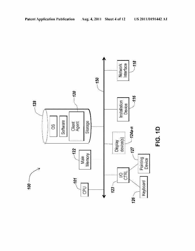
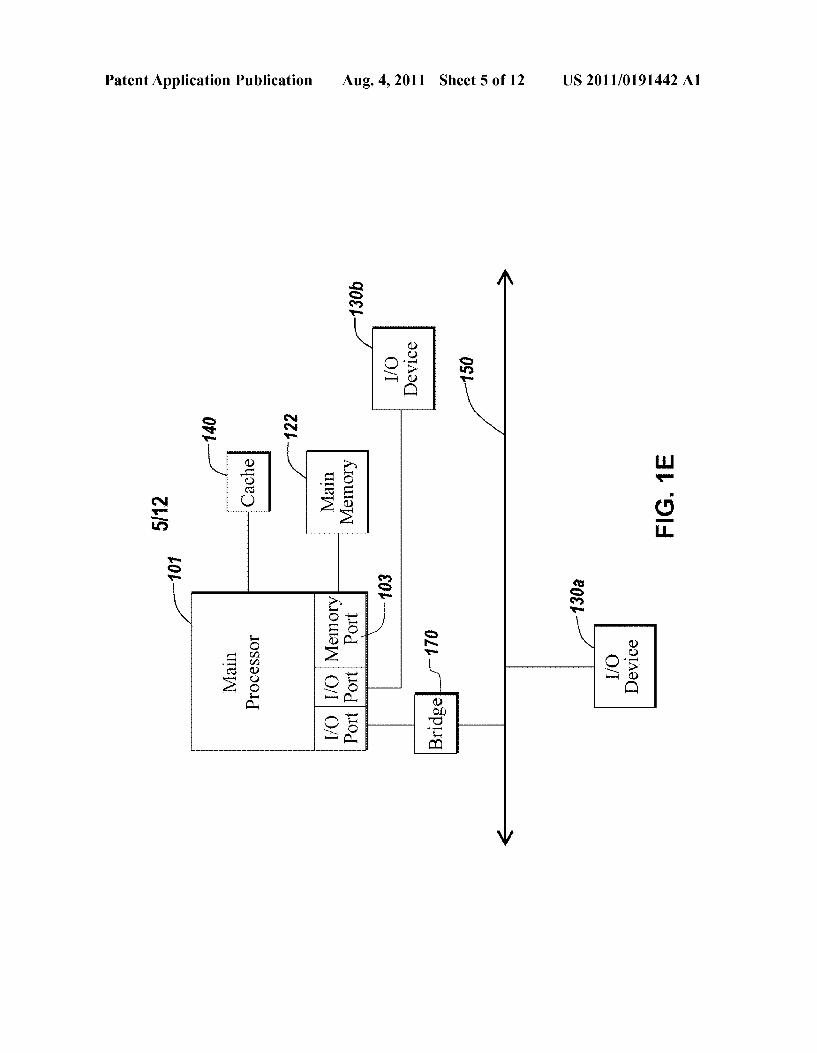
[0056] The client 102, server 106, and appliance 200 and 205 may be deployed as and/ or executed on any type and form of computing device, such as a computer, netWork device or appliance capable of communicating on any type and form of netWork and performing the operations described herein. FIGS. 1C and 1D depict block diagrams of a computing device 100 useful for practicing an embodiment of the client 102, server 106 or appliance 200. As shoWn in FIGS. 1C and 1D, each computing device 100 includes a central processing unit 101, and a main memory unit 122. As shoWn in FIG. 1C, a computing device 100 may include a visual display device 124, a keyboard 126 and/or a pointing device 127, such as a mouse. Each computing device 100 may also include addi tional optional elements, such as one or more input/output devices 130a-130b (generally referred to using reference numeral 130), and a cache memory 140 in communication With the central processing unit 101. [0057] The central processing unit 101 is any logic circuitry that responds to and processes instructions fetched from the main memory unit 122. In many embodiments, the central processing unit is provided by a microprocessor unit, such as: those manufactured by Intel Corporation of Mountain VieW, Calif; those manufactured by Motorola Corporation of Schaumburg, Ill.; those manufactured by Transmeta Corpo ration of Santa Clara, Calif.; the RS/6000 processor, those manufactured by International Business Machines of White Plains, N.Y.; or those manufactured by Advanced Micro Devices of Sunnyvale, Calif. The computing device 100 may be based on any of these processors, or any other processor capable of operating as described herein. [0058] Main memory unit 122 may be one or more memory chips capable of storing data and alloWing any storage loca tion to be directly accessed by the microprocessor 101, such as Static random access memory (SRAM), Burst SRAM or SynchBurst SRAM (BSRAM), Dynamic random access memory (DRAM), Fast Page Mode DRAM (FPM DRAM), Enhanced DRAM (EDRAM), Extended Data Output RAM (EDO RAM), Extended Data Output DRAM (EDO DRAM), Burst Extended Data Output DRAM (BEDO DRAM), Enhanced DRAM (EDRAM), synchronous DRAM (SDRAM), JEDEC SRAM, PC100 SDRAM, Double Data Rate SDRAM (DDR SDRAM), Enhanced SDRAM (ES DRAM), SyncLink DRAM (SLDRAM), Direct Rambus DRAM (DRDRAM), or Ferroelectric RAM (FRAM). The main memory 122 may be based on any of the above described memory chips, or any other available memory chips capable of operating as described herein. In the embodi ment shoWn in FIG. 1C, the processor 101 communicates With main memory 122 via a system bus 150 (described in more detail beloW). FIG. 1C depicts an embodiment of a computing device 100 in Which the processor communicates directly With main memory 122 via a memory port 103. For example, in FIG. 1D the main memory 122 may be DRDRAM. [0059] FIG. 1D depicts an embodiment in Which the main processor 101 communicates directly With cache memory 140 via a secondary bus, sometimes referred to as a backside bus. In other embodiments, the main processor 101 commu
Aug. 4, 2011
nicates With cache memory 140 using the system bus 150. Cache memory 140 typically has a faster response time than main memory 122 and is typically provided by SRAM, BSRAM, or EDRAM. In the embodiment shoWn in FIG. 1C, the processor 101 communicates With various I/O devices 130 via a local system bus 150. Various busses may be used to connect the central processing unit 101 to any of the I/O devices 130, including aVESA VL bus, an ISA bus, an EISA bus, a MicroChannel Architecture (MCA) bus, a PCI bus, a PCI-X bus, a PCI-Express bus, or a NuBus. For embodiments in Which the I/O device is a video display 124, the processor 101 may use an Advanced Graphics Port (AGP) to commu nicate With the display 124. FIG. 1D depicts an embodiment of a computer 100 in Which the main processor 101 commu nicates directly with U0 device 130 via HyperTranspor‘t, Rapid I/O, or In?niBand. FIG. 1D also depicts an embodi ment in Which local busses and direct communication are mixed: the processor 101 communicates with U0 device 130 using a local interconnect bus While communicating with U0 device 130 directly. [0060] The computing device 100 may support any suitable installation device 116, such as a ?oppy disk drive for receiv ing ?oppy disks such as 3.5-inch, 5.25-inch disks or ZIP disks, a CD-ROM drive, a CD-R/RW drive, a DVD-ROM drive, tape drives of various formats, USB device, hard-drive or any other device suitable for installing softWare and pro grams such as any client agent 120, or portion thereof. The computing device 100 may further comprise a storage device 128, such as one or more hard disk drives or redundant arrays of independent disks, for storing an operating system and other related softWare, and for storing application softWare programs such as any program related to the client agent 120. Optionally, any of the installation devices 116 could also be used as the storage device 128. Additionally, the operating system and the softWare can be run from a bootable medium, for example, a bootable CD, such as KNOPPIX®, a bootable CD for GNU/Linux that is available as a GNU/Linux distri bution from knoppix.net. [0061] Furthermore, the computing device 100 may include a netWork interface 118 to interface to a Local Area NetWork (LAN), Wide Area NetWork (WAN) or the Internet through a variety of connections including, but not limited to, standard telephone lines, LAN or WAN links (e.g., 802.11, T1, T3, 56 kb, X.25), broadband connections (e.g., ISDN, Frame Relay, ATM), Wireless connections, or some combi nation of any or all of the above. The netWork interface 118 may comprise a built-in netWork adapter, netWork interface card, PCMCIA netWork card, card bus netWork adapter, Wire less netWork adapter, USB netWork adapter, modem or any other device suitable for interfacing the computing device 100 to any type of netWork capable of communication and performing the operations described herein. [0062] A Wide variety of I/O devices 130a-130n may be present in the computing device 100. [0063] Input devices include keyboards, mice, trackpads, trackballs, microphones, and draWing tablets. Output devices include video displays, speakers, inkjet printers, laser print ers, and dye-sublimation printers. The I/O devices 130 may be controlled by an I/O controller 123 as shoWn in FIG. 1C. The U0 controller may control one or more I/ O devices such as a keyboard 126 and a pointing device 127, e.g., a mouse or optical pen. Furthermore, an I/O device may also provide storage 128 and/or an installation medium 116 for the com puting device 100. In still other embodiments, the computing
US 2011/0191442 A1
device 100 may provide USB connections to receive hand held USB storage devices such as the USB Flash Drive line of devices manufactured by TWintech Industry, Inc. of Los Alamitos, Calif. [0064] In some embodiments, the computing device 100 may comprise or be connected to multiple display devices 12411-12411, Which each may be of the same or different type and/or form. As such, any of the I/O devices 13011-13011 and/or the I/O controller 123 may comprise any type and/or form of suitable hardWare, softWare, or combination of hard Ware and softWare to support, enable or provide for the con nection and use of multiple display devices 12411-12411 by the computing device 100. For example, the computing device 100 may include any type and/or form of video adapter, video card, driver, and/or library to interface, communicate, con nect or otherWise use the display devices 12411-12411. In one embodiment, a video adapter may comprise multiple connec tors to interface to multiple display devices 12411-12411. In other embodiments, the computing device 100 may include multiple video adapters, With each video adapter connected to one or more of the display devices 12411-12411. In some
embodiments, any portion of the operating system of the computing device 100 may be con?gured for using multiple displays 12411-12411. In other embodiments, one or more of the display devices 12411-12411 may be provided by one or more other computing devices, such as computing devices 10011 and 1001) connected to the computing device 100, for example, via a netWork. These embodiments may include any type of softWare designed and constructed to use another computer’s display device as a second display device 12411 for the computing device 100. One ordinarily skilled in the art Will recogniZe and appreciate the various Ways and embodi ments that a computing device 100 may be con?gured to have multiple display devices 12411-12411. [0065] In further embodiments, an I/O device 130 may be a bridge 170 betWeen the system bus 150 and an external com munication bus, such as a USB bus, anApple Desktop Bus, an RS-232 serial connection, a SCSI bus, a FireWire bus, a FireWire 800 bus, an Ethernet bus, anAppleTalk bus, a Giga bit Ethernet bus, an Asynchronous Transfer Mode bus, a HIPPI bus, a Super HIPPI bus, a SerialPlus bus, a SCI/LAMP bus, a FibreChannel bus, or a Serial Attached small computer system interface bus. [0066] A computing device 100 of the sort depicted in FIGS. 1C and 1D typically operate under the control of oper ating systems, Which control scheduling of tasks and access to system resources. The computing device 100 can be running any operating system such as any of the versions of the Microsoft® WindoWs operating systems, the different releases of the Unix and Linux operating systems, any version of the Mac OS® for Macintosh computers, any embedded operating system, any real-time operating system, any open source operating system, any proprietary operating system, any operating systems for mobile computing devices, or any other operating system capable of running on the computing device and performing the operations described herein. Typi cal operating systems include: WINDOWS 3.x, WINDOWS 95, WINDOWS 98, WINDOWS 2000, WINDOWS NT 3.51, WINDOWS NT 4.0, WINDOWS CE, and WINDOWS XP, all of Which are manufactured by Microsoft Corporation of Redmond, Wash. ; MacOS, manufactured by Apple Computer of Cupertino, Calif.; OS/2, manufactured by International Business Machines of Armonk, N.Y.; and Linux, a freely available operating system distributed by Caldera Corp. of
Aug. 4, 2011
Salt Lake City, Utah, or any type and/or form of a Unix operating system, among others. [0067] In other embodiments, the computing device 100 may have different processors, operating systems, and input devices consistent With the device. For example, in one embodiment the computer 100 is a Treo 180, 270, 1060, 600 or 650 smart phone manufactured by Palm, Inc. In this embodiment, the Treo smart phone is operated under the control of the PalmOS operating system and includes a stylus input device as Well as a ?ve-Way navigator device. More over, the computing device 100 can be any Workstation, desk top computer, laptop or notebook computer, server, handheld computer, mobile telephone, any other computer, or other form of computing or telecommunications device that is capable of communication and that has su?icient processor poWer and memory capacity to perform the operations described herein.
B. System and Appliance Architecture
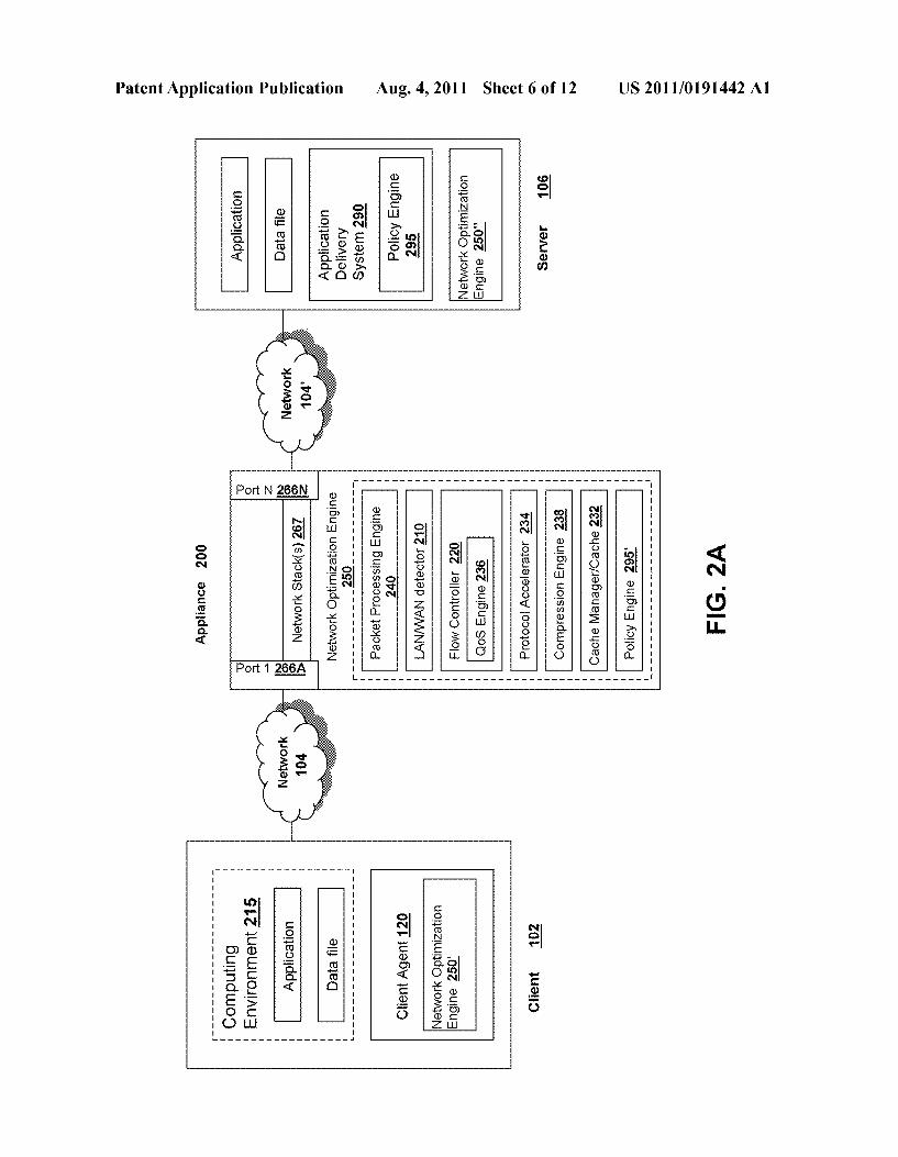
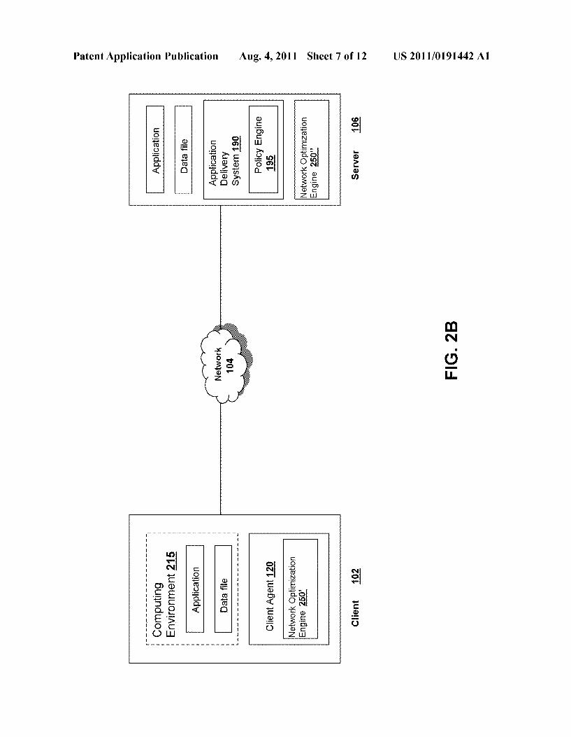
[0068] Referring noW to FIG. 2A, an embodiment of a system environment and architecture of an appliance 200 for delivering and/or operating a computing environment on a client is depicted. In some embodiments, a server 106 includes an application delivery system 290 for delivering a computing environment or an application and/ or data ?le to one or more clients 102. In brief overvieW, a client 102 is in communication With a server 106 via netWork 104 and appli ance 200. For example, the client 102 may reside in a remote o?ice of a company, e.g., a branch of?ce, and the server 106 may reside at a corporate data center. The client 102 has a client agent 120, and a computing environment 215. The computing environment 215 may execute or operate an appli cation that accesses, processes or uses a data ?le. The com puting environment 215, application and/or data ?le may be delivered via the appliance 200 and/ or the server 106. [0069] In some embodiments, the appliance 200 acceler ates delivery of a computing environment 215, or any portion thereof, to a client 102. In one embodiment, the appliance 200 accelerates the delivery of the computing environment 215 by the application delivery system 290. For example, the embodiments described herein may be used to accelerate delivery of a streaming application and data ?le processable by the application from a central corporate data center to a remote user location, such as a branch o?ice of the company. In another embodiment, the appliance 200 accelerates trans port layer traf?c betWeen a client 102 and a server 106. In another embodiment, the appliance 200 controls, manages, or adjusts the transport layer protocol to accelerate delivery of the computing environment. In some embodiments, the appli ance 200 uses caching and/or compression techniques to accelerate delivery of a computing environment. [0070] In some embodiments, the application delivery management system 290 provides application delivery tech niques to deliver a computing environment to a desktop of a user, remote or otherWise, based on a plurality of execution methods and based on any authentication and authorization policies applied via a policy engine 295. With these tech niques, a remote user may obtain a computing environment and access to server stored applications and data ?les from any netWork connected device 100. In one embodiment, the application delivery system 290 may reside or execute on a server 106. In another embodiment, the application delivery system 290 may reside or execute on a plurality of servers 10611-10611. In some embodiments, the application delivery