Systems Reference Library IBM System/360 System Summary This publication provides basic information about the IBM System/360; its objective is to help readers achieve a general understanding of this data processing system and of the interrelationships of its models and components. The system concepts, features, individual models, and programming systems are briefly discussed, and the input/output devices and terminals are listed. It is assumed that the reader has a basic knowledge of data processing systems, as given in the Introduction to IBM Data Processing Systems, GC20-1684. More detailed information about System/360 is available in the IBM System/360 Principles of Operation, GA22-6821. Publications further describing the individual System/360 models, programming systems, input/output devices, and teleprocessing equipment are listed in the IBM System/360 and System/370 Bibliography, GA22-6822, and the IBM Teleprocessing Bibliography, GA24-3089. This publication does not apply to System/360 Model 20. All Model 20 publications are listed in the IBM System/360 Model 20 Bibliography, GA26-3565. File Number S360-00 Order No. GA22-681 0-12
Transcript
Systems Reference Library
IBM System/360 System Summary
This publication provides basic information about the IBM System/360; its objective is to help readers achieve a general understanding of this data processing system and of the interrelationships of its models and components. The system concepts, features, individual models, and programming systems are briefly discussed, and the input/output devices and terminals are listed.
It is assumed that the reader has a basic knowledge of data processing systems, as given in the Introduction to IBM Data Processing Systems, GC20-1684.
More detailed information about System/360 is available in the IBM System/360 Principles of Operation, GA22-6821. Publications further describing the individual System/360 models, programming systems, input/output devices, and teleprocessing equipment are listed in the IBM System/360 and System/370 Bibliography, GA22-6822, and the IBM Teleprocessing Bibliography, GA24-3089.
This publication does not apply to System/360 Model 20. All Model 20 publications are listed in the IBM System/360 Model 20 Bibliography, GA26-3565.
File Number S360-00 Order No. GA22-681 0-12
Thirteenth Edition (January 1974)
This major revIsion obsoletes GA22-6810-11 and Technical Newsletters GN22-0344 and GN22-0450.
Numerous changes were made in this manual. Among the changes is the deletion of the descriptions of th.e input/output devices and terminals. In general, any significant technical change (revision, addition, or deletion) is indicated by a vertical bar to the left of the change
Hrief descriptions of most input/output devices and terminals attachable to System/360 are in the IBM System/370 System Summary, GA22-7001. Attachment information for these input/output devices and terminals is in the IBM System/360 Input/Output Configurator, GA22-6823.
Changes are periodically made to the specifications herein; before using this publication in connection with the operation of IBM systems, refer to the latest IBM System/360 and System/370 Bibliography, GA22-6822 and associated technical newsletters for the editions that are applicable and current.
Requests for copies of IBM publications should be made to your IBM representative or to the IBM branch office serving your locality.
This manual was prepared by the IBM System Products Division, Product Publications, Dept. B98, P. O. Box 390, Poughkeepsie, N. Y. 12602. A form for readers' comments is provided at the back of this publication. If the form has been removed, comments may be sent to the above address. Comments become the property of IBM.
Section 1. Introduction to IBM System/360 1-1 Specific Operating Systems 4-1 Programming Systems Glossary 4-3
Section 2. System/360 Basic Structure 2-1 Data Formats 2-1 Section 5. Teleprocessing, Data Acquisition, Data Representation 2-1 and Process Control 5-1
Main Storage 2-2 Teleprocessing 5-1 Addressing 2-3 Requirements of a Teleprocessing System 5-2 Data Positioning. 2-3 Transmission Directions and Modes 5-2 Performance Factors 24 Terminal Connections to Communications Lines 5-2
Central Processing Unit . 24 Modems 5-3 Arithmetic and Logic Operations 24 Data Acquisition and Process Control 5-3 Instruction Formats 2-5 System Control Panel 2-6
Input/Output 2-6 Section 6. System/360 Models 6-1 Channels. 2-6 Model 22 6-1 I/O Devices 2-8 System Components 6-2 Control Units 2-8 Programming Support 6-2 I/O Interface. 2-8 Model 25 6-3
Interruption System 2-8 System Components 6-3 Programming Support 6-4
Section 3. System/360 Features 3-1 Model 30 6-5 Main Storage Features 3-1 System Components 6-5
Processor Storage Capacities '3-1 Programming Support 6-6 Large-Capacity Storage (LCS), or IBM 2361 Model 40 6-7
Core Storage 3-1 System Components 6-7 Shared Main Storage 3-1 Programming Support 6-8 Storage Protection 3-1 Model 50 6-9
Central Processing Unit Features 3-3 System Components 6-9 Instruction Sets . 3-3 Programming Support 6-10 Decimal Feature 3-3 Model 65 6-11 Floating-Point Feature 3-3 System Components 6-11 Extended-Precision Floating-Point Feature 3-3 Programming Support 6-12 Direct Control and External Interrupt 3-3 Model 67 6-13 Byte-Oriented Operand 3-3 System Components 6-14 Dynamic Address Translation 3-3 Programming Support 6-15 Emergency Power-Off Control 3-4 Model 75 6-16 High-Speed Buffer Storage 3-4 System Components 6-16 Timers 3-4 Programming Support 6-l7 Time Sharing 3-4 Model 195 6-18
Channel Features 3-4 System Components 6-18 Channel-to-Channel Adapter 34 Programming Support 6-19
System Features. 34 Compatibility Features for Other IBM Systems 34 Section 7. Input/Output Devices 7-1 System Partitioning (Duplex Model 67-2) 3-5
Section 4. System/360 Programming Systems 4-1 Section 8. Teleprocessing Terminals 8-1 Basic Programming Support (BPS) 4-1 Special Systems Support 4-1 Operating Systems-General Facts 4-1 Index. X-I
IBM System/360 Model 22
IBM System/360 provides a wide range of computing versatility and power combined with exceptional reliability and efficiency. The different models within System/360 are identical in concept and compatible in programming, but are scaled in size, speed, and cost to fit the needs of different users. The many ways System/360 meets these needs are discussed in the following paragraphs.
System/360 is a general-purpose .s·y.s-tem. System 1360 can be tailored for a wide variety of applications:
1. Commercial applications, which require decimal arithmetic, variable-length fiC'lds, and editing capahilities.
2. Scientific applications, which require larger storage capacities and high-speed binary arithmetic.
3. Communications, which often requires a large number of communication terminals and fast response.
4. Control applications, which require fast internal processing speeds and high reliahility.
.5. Any combination of the preceding applications.
System/360's design is open-ended. This permits System 1.360· to easily expand and to incorporate new features, devices, and technology. One examplc' is the system's capability of addressing over 16 million bytes of main storage, thereby anticipating larger storage' needs than those already met. Another example is the use of an eight-bit characte'r cock that allows for as many as 2.56 characte'rs, permitting easy code' expansion for future needs.
System '360 offers a tcide choice of models, each tcit11 an extensit:e selection of facilities. The different models offer users a choice of performance ranges. Each model also has a wiele selection of main storage capacitic.;, I '0 de\'ic('s, programming support and features, permitting the systcn1 to he tailored to the user's nceds. As his nceds change. his system can often he modified correspondingly.
System /360 offers system compatilJilit!l. \Yl1('n expansion of data processing operations requires a larger model of Syst('m:360, system compatibility ensures easy transition. This characteristic permits programs that operate on (1)e model of SY'stel11 ·:360 to opnate on other models that ha\'(' the m'cessary configuration ,mel features.
Section 1. Introduction to IBM System/360
Transition to System/360 from most other IBM systems is facilitated by the compatibility features, which are combinations of circuitry and programming that enable System/360 to execute programs written for other IB:\f systems. In many cases, tbe programs are executed faster on the System/360 than on the system for which they were written.
System/360 has self-superVision capabilities. This is due primari1y to the System/360 interruption system and to the control programs. The interruption system permits the central processing unit ( CPU ) to:
1. Quickly change state as a result of conditions in the CPU itself, in the input loutput (I/O) units, or external to the system.
2. Identify the type of interruption. 3. Store the current status information to permit later
resetting of the status that the CPU had before the interruption.
The interruption system operates in conjunction with a control program. System/360 models are designed to operate with a control program, an integral part of most System 1360 programming systems. \Vith a control program:
1. Data and programs processed by System/360 are systematically organized, identified, stored, and retrieved.
2. A continuous series of jobs can he performed by System /360 with little or no operator interventIOn.
.3. Several data processing tasks can be performed ccncurrently, therehy increasing the total throughput of System 1.360.
System 1360 permits easy attachment of many different 110 dct:ices that can operate concurrently tcith data processing. To overlap data processing and I/O operations efficiently, System /360 uses channels; these units relieve the central processing unit of the direct handling of I '0 operations. One type of channel (the selector channel) is used primarily to control high-speed 1·0 deviccs, such as magnetic tape units and disk storage units; another type (the multiplexer channel) simllltan('ously controls a nnmher of lower-speed de\·ices. sllch as communication terminals, printers, and punched-card dcvices. The channels operate through the System '.'360 I '0 interface, which provides the system with a uniform method of easily attaching many
Introduction to IBM System/360 1-1
different I/O devices. Both the channels and the 10
interface facilitate the attachment of ncw I 0 devices, developed to meet the needs of users.
System; 360 offers high reliability. This is done by using more reliahle components and circuits. parity checking, error-checking and correction circuitry, the System/360 interruption system. instruction retry. and system compatibility.
The reliability of System /360 is significantly higher than that of its predecessors hecause of the reliability of its basic component circuitry, which may be solid logic technology (SLT) or any of the more advanced circuit technologies. Parity checking, used on all
1-2
models of System /.360, increases reliability by monitoring hoth data anc1 instructions for invalic1 information. On some rnodc1s, parity checking is complemented hy error-checking and correction circuitry. Error checking is also done during program execution hy the interruption system, clearly separating interruptions caused by either machine or programming errors. thus helping to minimize downtime. Systems equipped with the instruction retry feature automatically attempt to re-ex('cute failing instructions, thereby reducing the possibility of program interruption. System compatibility contrihutes to reliability by permitting the coupling of units to form a system that is operational even though some components may fail.
The basic structure of a System/360 model (Figure 2-1) consists of main storage, a central processing unit (CPU), one or more channels, and input/output devices generally attached to the channels through channel units and the System/360 I/O interface.
Data Formats
The system transmits data between main storage and CPU in multiples of eight bits. Each eight-bit unit of data is called a byte, the basic building block of all formats in System/360. A ninth bit, the parity or check bit, is transmitted with each byte and carries odd parity in the byte. The parity bit cannot be affected by the program; its only purpose is to cause an interruption when a parity error is detected. In this manual, references to data exclude the mention of the associated parity bits.
Bytes may be handled separately, or they may be grouped in fields. The halfuord, u.;ord, and doubleword are fields of consecutive bytes; a halfword has two bytes, a word has four bytes, and the doubleword
Main Storage
Central Processing Unit (CPU)
-- CPU - Channel Control Lines -- Doto Trcn5fer lines
Channels I/O Interface Control Units
Figure 2-1. Organization of a Representative System/.'360 Model
Section 2. System/360 Basic Structure
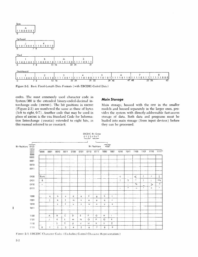
has eight bytes. These fields make up the basic fixedlength data formats (Figure 2-2).
Data formats are either fixed-length or variablelength. During processing, their field length is either implied by the operation to be performed or it is stated explicitly as part of the instnlction.
Data Representation
In System/360, data (whether numeric, alphabetic, or alphameric) is processed in multiples of an eight.:bit byte. The data may be in binary form (as numeric data for most scientific computations) or it may be in a binary code. Coding permits data to be represented by characters (for example, 1, 2, A, B, and 0) on devices such as card readers, visual display units, and printers. These devices are code-dependent; that is, their operation depends on the code used to represent the characters.
The eight-bit byte provides for as many as 2.56 characters, which allows for future code expansion and permits System/360 to accept most present and future
Input/Output (I/O) Devices
System/360 Basic Structure 2-1
Halfword
Word
IBM 3
11001001110000101101010011110011 o 7 8 15 16 23 24 31
Doubleword
1 2 1111000111110010111 o 7 8 15 16
Figure 2-2. Basic Fixed-Length Data Formats (with EBCDIC-Coded Data)
Main Storage
1 1 56
codes. The most commonly used character code in System/360 is the extended binary-coded-decimal interchange code (EBCDIC). The bit positions in EBCDIC
(Figure 2-3) are numbered the same as those of bytes (left to right, 0-7). Another code that may he used in place of EBCDIC is the USA Standard Code for Infonnation Interchange (USASCII) extended to eight bits, in this manual referred to as USASCII-8.
Main storage, housed with the CPU in the smaller models and housed separately in the larger ones, providcs the system with directly-addressable fast-access storage of data. Both data and programs must be loaded into main storage (from input devices) before they can he processed.
I --'-
Bit Positions 0123
1111 0000
0001
0010
0011
0100
0101
0110
0111
1000
1001
1010
1011
1100
1101
1110
1111
EBCDIC Bit Order 01234567
I -Bit Positions 4567 __ ----------------____________ ________________ ~A~ ________________________________________________ ~
r------- A I B : C --T~ii-=-! E F _ ~ __ <?-.-J H I i I
I I --I
r-----___ J_ i ~ . +i-"-~-~-! -P-j Q : R I 1ST U i ~-1 VI ,X Y ~ z I =± ot-l~!-~-- -4:5 --6--r7 :-at 9
i I
Figure 2-:1. EBCDIC Character Codes (E.\c1udin!..': Control Character Representations)
2-2
Addressing
Byte locations in main storage are consecutively numbered starting with 0; each number is the address of the corresponding byte. A group of bytes in storage is addressed by the leftmost hyte of the group. The number of bytes in the group is either implied by the instruction format or explicitly defined by the instruction itself. Anticipating future storage needs, the addressing arrangement uses a 24-bit binary address, which gives System/360 the capability of addressing as many as 16,777,216 bytes of storage. This set of mainstorage addresses includes some locations reserved for special purposes.
Data Positioning
Restrictions on the positioning of data in storage depend on whether a data field is variable- or fixedlength. Variable-length fields may start on any byte location, but fixed-length fields (such as halfwords, words, and doublewords) in most models must be located in main storage on integral boundaries. A houndary is integral for a unit of data when its main storage address is a multiple of that unit's length in hytes. For example, halfwords (two bytes) must have main storage addresses that are multiples of two. Figure 2-4 shows integral boundaries for the common
I units of data, showing simplified main storage addresses as
fooII-------------- Main Storage Locations (with Simplified Addresses)
7 "7 "7 "7
OOUBL. E14/0RO
~ ~ ~ : v< "7 7
~ : F: 7
A I I
A I
I
I
I I
~~
"7 wo:oiJ ~
"7 7
V ~ Figure 2-4. Representative Integral Boundaries for HaJf\\'0 r<L, \\"onk and Douhle\\"(mls in Main Storage
Systcm/.360 Basic Structure 2-.3
four-digit decimal numbers (0000, 000 1, 0002, etc.) rather than the 24-digit binary numbers actually used. Sequential halfword addresses are shown in Figure 2-4 as 0000, 0002, 0004, etc. For integral boundaries, words (four bytes) must have addresses that are multiples of four (shown in Figure 2-4 as 0000, 0004, 0008, etc.), and doublewords (eight bytes) must have addresses that are multiples of eight (shown in Figure 2-4 as 0000, 0008, 0016, etc.).
For exception to the boundary restriction, see "ByteOriented Operand" discussed in Section 3.
Performance Factors
The variety of main-storage units available for the System/360 models permits the system to be tailored to suit the individual needs of the user. The units differ in capacities,- access widths, cycle times, and degrees of interleaving.
Depending on the model, storage capacities range from 16K (16,384) bytes to 4,096K (4,194,304) bytes. (In this manual, 1K = 1,024.) Additional directly-addressable storage is available for several models, permitting main storage increases (in rounded numbers) of one to eight million bytes.
Storage Access Width is the number of bytes transferred to or from main storage in each access. As access width increases, the quantity of data that may be transferred per unit time increases. The width, which is model-dependent, ranges from 1 to 16 bytes.'
Storage Cycle Time is a measure of storage speed and is defined as the length of time that main storage is busy whenever a reference is made to it. The shorter the cycle time, the greater the number of operations that can be performed in any time interval. Fixed for each model, this cycle time ranges from 0.75 to 2 .. 5 microseconds.
Storage interleaving, available with the larger System/360 models, increases the number of mainstorage accesses started in a storage cycle, thereby significantly increasing the amount of data accessed per unit. time. With interleaving, the number of accesses started during a storage cycle can be 2, 4, 8, or 16, depending on the main-storage capacity.
Central Processing Unit The central processing unit (cpu) is the controlling center of System/360. It provides facilities for:
Addressing main storage. Fetching and storing data. Arithmetic and logical processing of data. Executing instructions in a desired sequence. Initiating communication between main storage and input!
output (I/O) devices.
The CPU also provides 16 general registers and 4 floating-point registers. These registers are accessible
2-4
to the programmer and are capable of receiving data, holding it, permitting it to be operated on, and transferring it. The general registe!s are used primarily for fixed-point, logic, and addressing operations. The floating-point registers are used only for floating-point arithmetic.
Two major sections of the CPU are the system control section and the arithmetic/logic unit. The system control section directs the sequential accessing of instructions and coordinates both instruction execution and storage fetches. The arithmetic/logic unit, as its name implies, performs the arithmetic and logic operations.
Arithmetic and Logic Operations
The arithmetic and logic operations fall into four classes: Decimal arithmetic Fixed-point arithmetic Floating-point arithmetic Logic operations
These classes differ in the data formats and field lengths used, the registers involved, and the operations provided.
Decimal Arithmetic
Decimal arithmetic, used principally for commercial applications, is performed on signed decimal numbers. Generally, decimal data entering and leaving the system via devices such as card reader-punches and printers is in zoned format (Figure 2-5). But, for processing and for storage in direct-access and magnetic-tape devices, decimal data is in packed format (Figure 2-6). Packing fits two decimal digits (or one digit and sign) per byte. Because only four binary digits are needed to express one decimal digit, packing permits more efficient handling of decimal data.
Packed data is taken from main storage, processed,. and returned to storage without the data passing through any general registers; this is called storage-to-storage processing. The decimal field length, specified by the instruction, can be expanded to as many as 31 digits plus sign, all packed in 16 bytes.
High-order Byte
Figure 2-5. Zoned Decimal Number Format
Figure 2-6. Packed Decimal Number Format
Fixed-Point Arithmetic
Fixed-point arithmetic is used to perform arithmetic operations on both data and storage addresses. This combined use permits the fixed-point instnlCtions (as wen as several logic instructions) to be used in address computation, permitting shifting and logical manipulation of address components.
The fixed-point binary word, the basic arithmetic operand in System/360, is a 32-bit signed integer (a 31-bit integer with a high-order sign bit). Halfword operands (Figure 2-7) can be specified in many operations where a fullword is not needed, thus improving both performance and storage use.
The 16 general registers, each four bytes (32 bits) wide, are used for fixed-point operations. General registers can also help keep fixed-point product and dividend precision by allowing adjacent registers to be coupled, effectively doubling the register width.
Floating-Point Arithmetic
Floating-point arithmetic, used primarily in scientific applications, greatly increases the speed, precision, and efficiency of computations. In System/360, this form of numeric representation can express positive or negative decimal values from about 10- 7
1'> to about 1076•
Floating-point numbers may be short (24-bit fractions, with up to seven decimal-place precision), or long (56-bit fractions, with up to 17 decimal-place precision), or extended (II2-bit fractions, with about 34-decimal-place precision). Floating-point fractions are made up of hexadecimal (base 16) digits, each consisting of four binary digits and having equivalent decimal (base 10) value of 0-15. The short format usually reduces execution times and increases the number of operands that can be stored; the long fonnat provides greater precision, and the extended format provides about twice the precision of the long format. (See also the "Extended-Precision Floating-Point Feature," discussed in Section 3.)
Halfword
153
0000000101010011 01 15
Fullword
3,223,939
00000000001100010011000110000011 01 31
Figure 2-7. Fixed-Point N"umber Fonnats (with Signed Binary Data)
Four Roating-point registers, each eight bytes wide, are provided. The availability of these registers eliminates much fetching and storing of intermediate results. The 16 general registers are also used, primarily for indexing and address arithmetic.
I.ogic Operations
The logic operations provide System 1360 with the ability to logically manipulate data. The manipulations include: comparing, testing, translating (character for character), editing (sign and punctuation control), and moving logic data. The data may have either a fixed- or variable-length format (Figures 2-8 and 2-9). Fixed-length data, processed through the general registers, may be one, four, or eight bytes long; variable-length data, processed stOrage-to-storage, can extend to 256 bytes.
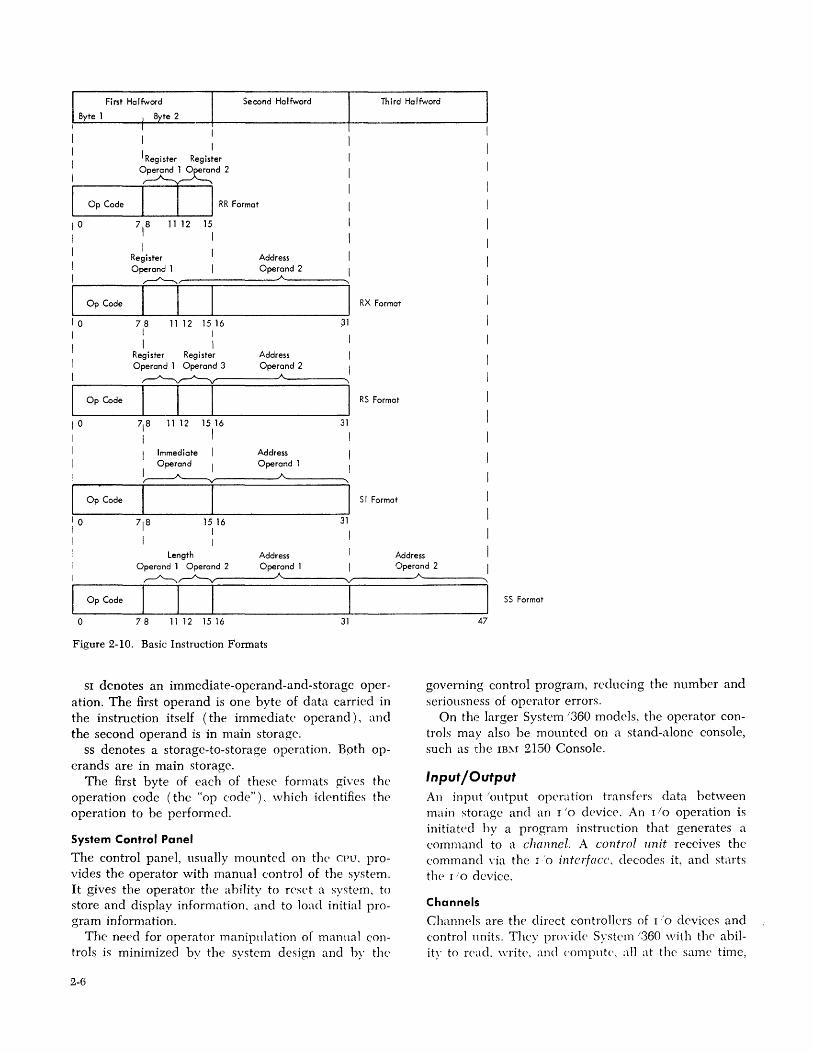
Instruction Formats
Main storage addressing and the execution of processing programs are directed· by the CPU. The instructions that make up these programs may be of several different formats, identified by the format codes RR, RX,
RS, sr, and ss (Figure 2-10). RR denotes a register-to-register operation. The op
erands are in general registers and the resuhs replace the first operand.
RX denotes a register-and-storage operation. The first operand is in a general register and the second operand is in a main storage location. This format includes a quantity for indexing the main storage address; the quantity is contained within another general register, which is used as an index register and is specified by the instruction. The results of an EX operation may replace the first operand, depending on the instruction.
RS denotes a register-and-storage operation. The first operand is in a general register, the second operand is in main storage, and a third may be specified by another general register.
Fixed-Length Logic Operand (One, Four, or Eight Bytes)
Logic Data
Figure 2-8. Fixed-Length Logic Format
Variable-Length Logic Operand (Up to 256 Byte..-s_) ___ ---,
B~e By to [ ~ ~ J Byte
o 8 16
Figure 2-9. Variable-Length Logic Format
System/360 Basic Structure 2-5
Second Halfword Third Halfword
RR Format
1° 718 11 12 15
I I I I
Register Address Operand 1 Operand 2
"...-A--..., A
Op Code I I L.-____ ...L-_--1 __ -'-_________ -Jl RX 'o.mat
I 10 71 8 15 16 I I I I I I Length Address Address
Operand 1 Operand 2 Operand 1 Operand 2
'I ~~ A
Op Code I I I I 0 78 11 12 15 16 31
Figure 2-10. Basic Instruction Fonnats
SI denotes an immediate-operand-and-storage opcration. The first operand is one byte of data carried in the instruction itself (the immediate operand), and the second operand is in main storage.
ss denotes a storage-to-storage operation. Both operands are in main storage.
The first byte of each of these formats gives the operation code (the "op code"). which identifies the operation to be performed.
System Control Panel
The control paneL usual1y mounted on the CPU. provides the operator with manual control of the system. It gives the operator the ahility to reset a system. to store and display information. and to load initial program information.
The need for operator manipulation of manual controls is minimized by the system design and hy the
2-6
A '\
I SS Format
47
governing control program, reducing the number and seriousness of operator errors.
On the larger System /360 models, the operator controls may also be mounted on a stand-alone console, such as 1:he IB~r 2150 Console.
Input/Output An input 'output operation transfers data between main storage and an I/O device. An I/O operation is initiated hy a program instrnction that generates a command to a channel. A control unit receives the command \'ia the 10 intcljacc. decodes it, and starts the I/O devicc.
Channels
Channels are tIl(' direct controllers of I/O devices and control nnits. They prm'icle System /360 with the ability to react write. and compute. all at the same timc,
by relieving the CPU of the task of communicating directly with the I/O devices.
Channels may be standalone units, complete with the necessary logical and storage capabilities, or they may time-share CPU facilities and be physically integrated with the CPU. The type available to any system model depends on the system model itself. In either case, the channel functions are identical. Channels may be implemented, however, to have different data transfer rates.
Functionally, the channel data path is divided into subchannels. To a programmer, each subchannel is treated as a separate channel, and is programmed as such.
Some subchannels can control several I/O devices, where- . as others can control only one; these are called shared and nonshared subchannels, respectively.
System/360 has three major types of channels: byte multiplexer, selector, and block mUltiplexer.
Byte Multiplexer Channels
Byte multiplexer channels separate the operations of high-speed devices from those of lower-speed devices. Channel operations are in either of two modes: byte mode for lower data rates, and burst mode for the higher.
In byte mode, the single data path of the channel can be shared by a large number of lower-speed I/O devices (such as card readers, printers, and terminals) operating concurrently; the channel receives and sends data to the I/O devices on demand.
Burst mode is forced by devices such as magnetic tape units, disks, or data cell storage, and is not under the control of the programmer. Such high-speed devices, having established a logical connection with a channel, usually stay connected to it for the duration of data transfer and thereby force the channel into burst-mode state.
The IBM 2870 Multiplexer Channel (Figure 2-11), a standalone unit used with Models 65-195, houses one byte multiplexer channel. Like the in-CPU byte multiplexer channels, the 2870's have byte multiplexer subchannels; additionally, 2870's can have selector subchannels.
Byte multiplexer subchannels may operate in either byte or burst mode, and may be of either the shared or nonshared type. In byte mode, all subchannels can operate concurrently provided the total load does not exceed channel capacity; each subchannel can operate one low- or medium-speed I/O device. In burst mode, one byte multiplexer subchannel monopolizes the byte multiplexer channel and operates one higher-speed I/O device.
Selector subchannels, which are of the shared type only, operate in burst mode; each can operate one I/O device concurrently with the byte multiplexer subchannels but can control as many as 16 I/O devices.
Figure 2-11. IBM 2870 Multiplexer Channel
Selector Channels
Selector channels transmit data to or from a single I/O device at a time. They can handle both high- and lower-speed I/O devices, but their burst-mode operation makes them especially suitable for high-speed devices. Each selector channel attaches up to eight I/O control units and can address as many as 256 I/O devices. One I/O device per selector channel can be transmitting data at any given time; no other I/O device on the channel can transmit data until all data is handled for the selected device.
In general, I/O operations on a selector channel are overlapped with processing, and all channels can operate simultaneously, provided that the processing unit's data rate capabilities are not exceeded. Nominal data rates for the selector channels range from 250 thousand bytes to 1.3 million bytes per second, depending on the system model and the channel options selected.
The IBM 2860 Selector Channel, a standalone unit used with Models 65-195, is similar in appearance to the 2870 Multiplexer Channel, and can house one, two, or three selector channels.
Block Multiplexer Channels
Block multiplexer channels have advantages of both byte multiplexer and selector channels in that they can concurrently operate many high-speed I/O devices on a single data path.
Block multiplexer channels operate in either of two modes: selector or block mUltiplex. Selector mode is
Systemj360 Basic Structure 2-7
functionally equivalent to selector channel operation, permitting attachment of all the I/O devices which can" attach to selector channels. In block mUltiplex mode, these channels permit interleaving (multiplexing) of channel programs for high-speed devices in such a way that channel programs can be initiated sooner and channels can be freed earlier than would be possible with selector channels. The byte and block multiplexer channels differ primarily in that the block multiplexer channels can operate with much faster I/O devices, and they transfer larger quantities of data per transmission. These quantities are referred to as blocks, and may include a number of records.
Block multiplexer channels provide a number of sub channels of the shared or nonshared type. The maximum data rates for block multiplexer channels vary with the System/ 360 models and channel options available, and range up to 3.0 million bytes per second.
The IBM 2880 Block Multiplexer Channel, the standalone unit used with the Model 195, is similar in appearance to the 2870, and houses either one or two block multiplexer channels.
I/O Devices
I/O devices fall into a number of categories, some of which overlap. They are used in and for: Auxiliary storage Machine and manual (keyed) input, both local and remote Teleprocessing Reading (or output) of external documents and displays Process control Data acquisition
Many I/O devices function with an external document, such as a punched card or a reel of magnetic tape. Others handle only electrical signals, such, as those in processcontrol and data acquisition systems.
One of the more common I/O devices in System/360 is the IBM 1052 Printer-Keyboard, which permits an operator to communicate directly with the system. Usually, the 1052 is located at the CPU; on larger models, it may also be mounted on a stand-alone console.
Control Units
Control units provide the logic circuitry and the storage areas (buffers) needed to operate the attached I/O devices. Yet, to the user, most control unit functions cannot be distinguished from I/O device functions.
A control unit may be single-path, shared-path, or multipath. A single-path unit, usually integrated with an I/O device, controls only only device. Both shared-path and multipath units can control more than one device and are usually stand-alone units. They differ in that a multipath unit permits several I/O devices to transfer data concurrently, whereas the shared-path unit does not.
2-8
I/O Interface
This set of lines provides a uniform method of attaching various I/O devices (through control units) to channels, making System/360 adaptable to a wide range of present and future devices and applications. The information format and the control signal sequences provided by the interface are independent of the type of control unit and channel.
Interruption System The interruption system permits System/360 to operate nonstop and greatly aids the efficient use of I/O
equipment. To make the interruption procedure as short and simple as possible, switching between the interrupted program and the control program (the program that services interruptions) must be efficient. This system operates as follows:
The complete status of System/360 is held in an eight-hyte program status u:ord (psw). This status information, which consists of the instruction address, condition code, storage protection key, etc., is saved when an interruption occurs, and is restored when the interruption has been serviced.
As soon as the interruption occurs, all current status information, together with an identification of the cause of the interruption is put into a psw. This "old" psw is stored at a fixed location. The system then automatically fetches a "new" psw from a different fixed location. Each class of interruption uses two fixed locations in main storage: one to receive the old psw when the interruption occurs, and the other to supply the new psw that governs the servicing of that class of interruption.
After the interruption has been serviced, a single instruction uses the old psw to reset the central processing unit to thp- status it had before the interruption.
Classes 01 Interruptions
The interruption system separates interruptions into five classes:
Program interruptions are caused by various kinds of programming errors; the exact type of error is identified in the old psw.
Supervisor Call interruptions are caused when the processing program issues an instruction to pass control to the part of the control program called the supervisor, which performs the supervisory functions associated with a task.
External interruptions are caused by an external device that requires attention, by the timer (an internal clocking device) going past zero, or by the operator pressing the interrupt key.
Machine Check interruptions are caused by the machine-checking circuits detecting an error.
I/O interruptions are caused by an I/O unit ending an operation or otherwise needing attention. Identification of the device and channel causing the interruption is stored in the old PSW; in addition, the status of the device and channel is stored in a fixed location.
Disallowing of Interruptions
Most interruptions may be either allowed or temporarily disallowed. When an interruption is disallowed, it is either delayed or does not take place, the outcome depending mainly on the class of interruption. The following can be disallowed: All I/O interruptions All external interruptions Some program interruptions The machine-check interruption
Specifically, while external and I/O interruptions are disallowed, any external or I/O interruption request is held pending until the interruption is allowed. (An interruption request signal is sometimes called, more brieRy, an "interrupt.") \Vhile program interruptions are disallowed, the corresponding program interruption request signals are disregarded and do not remain pending. \Vhile machine-check interruptions are disallowed, the first machine-check interruption request is held pending until the interruption is allowed, and any
machine-check interrupt beyond that first one is disregarded and does not remain pending.
Priority of Interruptions
During the execution of an instruction, several interruptive events may occur simultaneously. vVhen this occurs, the competing interruption requests are serviced in a fixed order of priority: Machine Check Program or Supervisor Call External Input/Output
The program and supervisor-call internlptions are mutually exclusive and cannot occur at the same time,
When more than one interruption requests service, the action consists of storing the old psw and fetching the new psw belonging to the interruption which is taken first. This new psw subsequently is stored without any instruction execution and the next interruption psw is fetched. This process continues until no more interruptions are to be serviced. When the last interruption request has been serviced, instruction execution is resumed using the psw last fetched. The order of execution of the interruption subroutines is, therefore, the reverse of the order in which the psw's are fetched.
Thus, the most important interruptions - I/O, external, program or supervisor call - are actually serviced first. Machine check, when it occurs, does not allow any other interruptions to be taken.
System/360 Basic Structure 2-9
This section describes the more prominent standard and optional features of System/360. Each feature is discussed under the heading for the system unit with· which it is most easily associated.
Some features are standard for some System/360 models and optional for others; and some features are available to only certain models. (See Section 6 for the features available with any specific model.)
Main Storage Features Main storage includes all directly-addressable storage; that is, both processor storage (which is part of every System/360) and 2361 Core Storage '( largecapacity storage), which is an optional feature for several models.
Processor Storage Capacities
Processor storage capacities offer a wide latitude in choosing the amount of storage required. The capacities vary from 16K (16384) bytes to 4,096K (4,194,304) bytes, depending on the system model. Available models have a choice of storage capacities.
Large-Capacity Storage (LCS), or IBM 2361 Core Storage
The main storage of several larger system models can be increased by adding large-capacity storage (Figure 3-1). The
increases are in blocks of either 1,048,576 or 2,097,152 bytes, to a maximum of 8,388,608 bytes. Available capacities are, in round numbers, 1, 2, 4, 6, or 8 million bytes. This storage, located in a separate unit, is addressed contiguously with processor storage. The number of bytes obtained per storage access, the storage protection features, and the other features of LCS (except its 8-microsecond speed) are the same as those of the processor storage of the system to which it is attached.
An advantage of LCS is that it accommodates. in protected storage, large records or vocabularies heretofore located in auxiliary storage media. thereby rcducing the number of time-consuming rdcrenc(:'s to I/O devices. Also, LCS can contain largc problems. with
Section 3. System/360 Features
extensive reference tables, throughout their execution. If two-way interleaving is specified for LCS, sequen
tial accesses are alternated between two LCS units and partially overlapped, with the effect, on Models 65 and 75, of increasing the maximum sequential access speed from a rate of 1 megabyte per second (8-microsecond speed with eight bytes per access) t02 megabytes per second (4-microsecond effective rate). In Model 50, only four bytes are fetched per storage access, and interleaving can be specified only where LCS is to be shared with a Model 65 or 75 in a System/360 multisyst<:'m. \Vhen interleaving is specified, available LCS
capacities are, in round numhers, 2, 4, or 8 million bytes.
Shared Main Storage
Central processing units may share either processor storage or large-capacity storage; the two capabilities are separate. The processor storage associated with two or more central processing units may be shared and addressed by each as a single storage unit. LCS
may be shared between two or more sytems; the LCS
addresses are then an extension of the larger of the two processor storages involved.
Storage Protection
Storage protection, made up of the store and fetch" protection features, prevents the unauthorized chang-, ing or use of the contents of main storage. Store protection prc>vents the contents of main storage from being altered by storage addressing errors in programs or input from I/O devices. Fetch protection prevents. the unauthorized fetching of data and instructions. from main storage. As many as 15 programs (with associated main storage areas) can he protected at one time.
Plotec:tion is achieved by dividing main storage into 2,048-hyte hlocks and by associating a five-bit storage key (Figure 3-2) with each hlock. Each storage. key may he thought of as a lock. Each hlock of storage, then, has its own <Clock." Two instructions are provided for assigning and inspecting the key, which contains a four-bit code. The same code may be used by many blocks, using binary codes 0001-1111 .
System/360 Features 3-1
Figure 3-1. IBM 2.'361 Core Storage (Large-Capacity Storage)
A user's right of access to storage is identified by a four-bit protection key (Figure :3-2), located in the program status word (ps\v) or in a special word used in channel operations. The protection key may he thought of as the key for the "lock". During a mainstorage reference (storing Of fetching). the storage key is compafed with the protection key associated with the reference. Access to the location is granted only when the four leftmost (high-order) hits of the storage key match the protection key. or when the protection key is zero (0000). \ \ 'hen hoth the store ancI fdch protection features arc instaJ1ccl. the rightmost (low-order) hit of the storage key ddermines whctlwf fetch protectioll is operatin' for the storage hlock associated \\'ith that key. If tIl<' hit is L fetch protection is operatin': if it is O. it is iI10[)CLltivC.
3-2
(
Storage Key 0
\.
(
Protection Key I 0
The "Lock" A
.---_/ Y
Compared Bits
A
y
The Key to the "Lock"
FetchProtection Bit
Figure :3-:2. Storage and Protection Keys, Showing !>.1atching Keys
Central Processing Unit features
Instruction Sets
The four major instruction sets available are: standard, scientific, commercial, and universal. The instructions that make up the standard instruction set provide System/360 with the basic processing instructions and are included with the other sets (Figure 3-3).
Commercio Instruction Set
J ""d"d { I Instruction 'l So>
Floating-Point Feoture Instructions
Fixed-Point Binary Arithmetic and Logic Instructions
Decimal Feature Instructions
Protection Feature Instructions
}
Scientific Instruction Set
Figure 3-3. System/360 Instruction Sets
Decimal Feature
Universal Instruction Set
This feature, especially useful in commercial operations, permits storage-to-storage decimal arithmetic operations and adds two instructions to assist in editing output. The decimal arithmetic instructions, when used with the standard instruction set, make up the commercial instruction set.
Floating-Point Feature
This feature, used primarily in scientific operations, permits calculations on data with a wide range of magnitude. Included with this feature are four 64-bit floating-point registers, which are used to perform these calculations. Operands can be selected for either 24-bit fractions (short precision) or 56-bit fractions (long precision). The floating-point instructions, when combined with the standard instruction set, make up the scientific instruction set.
Extended-Precision Floating-Point Feature
This feature permits floating-point operands to have 112-bit fractions (extended precision) compared to the 56-bit fractions available with long-precision floating-point arithmetic. It also permits results to be rounded from extended to long precision or from long to short precision.
Direct Control and External Interrupt
Direct control provides for exchanging control signals between two System/360 centra.l processing units, or between a System/360 and some specialized device, such as an analog-digital converter.
Direct control bypasses the channel by using the direct-control instructions and six external interruption lines, each of which, when pulsed, sets up the conditions for an external interruption. On some models, the external interrupt feature is available ( alone) for users who do not require (or have) the direct-control instructions, but who do require very fast program response to interruptions from time-dependent I/O devices such as the IBM 1419 Magnetic Character Reader and the IBM 1428 Alphameric Character Reader.
Byte-Oriented Operand
The byte-oriented operand feature allows the user to ignore, in part, the restriction that all operands in main storage must be at addresses that are integral multiples of the operand length. The user that takes advantage of this feature can reference fixed-point, floating-point, and logical operands of most RX- and RS- format instructions on any byte boundary.
The operation performed when the byte-oriented operand feature is used is called boundary alignment.
Programming Note: Boundary alignment causes instruction processing to proceed at less than optimal speed. Severe performance degradation may result when boundaries are unaligned.
Dynamic Address Translation
When many users have access to main storage, at any one time, the size of all programs being processed may exceed the capacity of main storage to accommodate them. Dynamic address translation, a combination bf advanced programming and circuitry, permits each user to program as though he had sole use of a large, contiguously addressable storage area. On the Model 67, this storage area is about 16 million or 4 billion bytes, depending on whether the standard or the extended dynamic address translation feature is chosen.
Only the active parts of programs reside in main storage; the remaining parts are stored in secondary storage devices. When these parts are called into main storage as needed, they are put in any available location. This procedure is automatic and places no burden on the programmer, who remains unaware that he is not the sole user of the system.
System/360 Features 3-3
Emergency Power-Off Control
Every System/360 CPU has an emergency power-off switch (on the system control panel), which can remove all electrical potential from all cable-connected units directly controlled by the CPU. Switches for installations with two or more cable-connected cpu's or cable-connected units that can be operated "off-line" (that is, not under direct control of a cpu) are required to be interconnected; this provides, in effect a single emergency power-off s\vitch. ,,7here units or systems in the same "room" or "area" arc not cableconnected, interconnection is strongly recommended.
High-Speed Buffer Storage
This unique feature, integrated with the CPU, can sharply reduce the time required for fetching currently used sections of main storage. On the Model 195, for example, the use of the buffer storage can reduce the' effective storage access time to about one-fifth of the actual storage access time.
The buffer, though much smaller in capacity than main storage, is quite efficient; most data fetches are made from the buffer rather than from main storage. The buffer achieves high efficiency by using a method of selecting data (for buffer storage) based on the sequential nature of most programs; that is, a storage fetch from some portion of main storage is likely to be followed by other fetches from subsequent locations in that same portion. In a system having huffer storage, such a portion (called a block) is loaded into the buffer, thereby readying the system for fast access to that block. In this way, the buffer is loaded with data most likely to be needed. \Vhen the buffer is
filled, a fetch from another portion of main storage causes new data to replace the least active block of data in the buffer.
Timers
The timer for System/360 is one of two types: a line frequency timer, or a high-resolution timer. Either type can be used as an interval timer to measure elapsed time, or can be programmed to tell the time of day. \Vith an appropriate program, either timer can be used to measure the duration of a job, poll a communication network at regular intervals (such as every minute or every 1.5 minutes), and record the time of program completions.
The line-frequency timer is counted down every 1 ',::lOth or 1 !60th of a second, depending on the line frequency. The hid/-resolution timer, however, uses
3-4
an oscillator that counts down at much shorter intervals (for example, every 13 microseconds on the ~Iodel 67).
An external interruption occurs automatically when time nms out, unless it is disaIlowed. The full duration for either timer, from the maximum stored value to the time when the interruption signal is generated, is 1.5.5 hours.
Time Sharing
Time sharing permits many users at remote terminals to use a system as if each were its only user. The computer may actually be switching among many terminals and processing many programs, giving each terminal a small slice of its available time. Time sharing is especially applicable to scientific and engineering problems, where: 1. The computations are not usually of a repetitive
nature. 2. It is advantageous to enter a problem piecemeal
into the computer and observe intermediate results before proceeding with the computation.
The Nlodel 67 can provide apparently simultaneous operations to various users at remote terminals. It can operate in this time-sharing mode 24 hours a day and process batch jobs during the time available between calls from remote terminals for computing.
Channel Features
Channel-to-Channel Adapter
This adapter provides a path for data transfers between two channels and synchronizes such transfers, providing systems with interchannel communication.
The channels may be either within the same system or on separate systems. Within one system, an adapter can permit the moving of blocks of data from one area in main storage to another. Connecting a channel of one system to a channel of another has the effect of interconnecting two cpu's.
The adapter uses one control-unit pgsition on each of the two connected channels, but only one channel need have the adapter.
System Features
Compatibility Features for Other IBM Systems
A number of features are available that permit operation of certain models of System/360 hy the use of programs written for other IB~f systems. These compatihility features are comhinations of circuitry and programming that make the System/360 able to read
programs written for the other system and to function like that systC'm. In many cases, the program nms much faster on System 1.360 than on the system for which it was written.
Compatibility features are also cal1cd emulators, hut not simulators. The latter, although they may perform the same function, do so with programming alone and thus nm slower.
A compatibility feature is particularly useful when the user needs time to convert his present programs to Systcm/.360 code hut at the same time, wants the advantages offered hy System /.360. In addition, using such a feature may eliminate the need for converting programs that arc seldom used.
Sufficient storage and appropriate or equivalent r/o devices must be available for the usc of a compatibility feature. Furthermore, the use of one compatibility feature usually precludes the use of another. Under unusual conditions, a feature may not be able to maintain exact compatibility; for example, programs that are tinw-dependent may not yield indentical results, and the handling of error conditions may differ.
In Figure 6-9 is a list of the compatibility features presently available and of the models of System/360 in which they may be incorporated if minimum and matching configuration requirements are met.
System Partitioning (Duplex Model 67-2)
A ~10del 67-2 with two cpu's may be partitioned into two independently operated systems. This can be achieved by programs that refer exclusively to certain components, but it is more desirable to partition components from the rest of the system by means of centrally located controls.
Such means are provided by the IB~I 2167 Configuration Unit, a console-likc component on which the partitioning switches and indicators are located. Partitioning from the required 2167 provides for operation of two-cpu systems as one multisystem (basic) or as independent systems. If one or more components become inoperatiH" partitioning permits them to be bypassed for continuing service.
Systern/360 h.:aturcs 3-5
The Systemj360 programming support supplied by IBM is aimed at minimizing the time and effort required by the user to produce and process programs. Programming support ranges from relatively simple programs to highly sophisticated operating systems. It falls in three categories: Basic Programming Support Special Systems Support Operating Systems
Basic Programming Support (BPS)
The BPS programs provide support for minimum card and tape configurations. BPS furnishes a large number of independent programs, each performing its specific functions, and provides translators for the following programming languages: Assembler Report Program Generator (HPG) FORTHAX
BPS also includes utility programs (e.g., write tape to cards, write disk to tape), sort /merge programs, and Autotest (a program testing and modifying facility). Other BPS programs support applications for optical and magnetic character readers.
Most BPS programs require only 8K bytes of main storage (K = 1,024).
Special Systems Support
Model 44, a scientific and engineering system, and Model 67, a time-sharing system, have special programming support consistent with the particular applications of these systems. (Support for these models is discussed briefly in Section 6.)
Operating Systems-General Facts
An operating system is a collection of programs th:.~t
provides for the preparation and execution of the user s problem programs (johs). IBM-supplied operating systems are designed to match the needs of the equipment configuration and the customer's job requin'ments.
All operating systems are either tape-resident or direct-access-resident and consist of two basic parts: Control program Processing pro.t?;rams
Control Program
The control program is the fram('work of an operating system: it has three distinct functions:
Section 4. System/360 Programming Systems
Job management Task management (Supervisor) Data management
Job f..,lanagement provides the facilities to read, interpret, initiate, and terminate jobs submitted for processing. It also provides the facilities for the operator to comunicate with the system.
Task f..,lanaf.!,ement is the core of an operating system. Because 'it performs the supervisory functions associated with the execution of a task, it is often called the supervisor. The functions provided generally in-
I clude interruption handling, resource allocation, fetching of non-resident routines, time supervision, and transient-error recovery.
Data ldanagement provides the functions of record blocking and deblocking, space allocation on direct access devices, processing of labels, and the transfer of data between main storage and external devices, all by means of various access methods. These functions allow data sets (sometimes called data files) and their processing the utmost independence from the I/O environment. The access methods used are wel1-defined and consistent ways of handling data sets according to their basic organization: sequential, indexed sequential, direct, partitioned, etc. Some access methods provid<.> automatic huffering facilities.
Processing Program
A processing program is defined as any program that is not a control program. Processing programs are kept on tape or direct access devices, as collections of data sets known as lihraries, and fall in three general categories:
Language Translators for Assembler, FOHTHA:\"
COBOL, PLil, etc. Sen;ice Programs such as utilities and sort imerge. User-'Vritten Problem Programs that lwcome part
of the operating system lihrary and are retrievable by name alone.
Specific Operating Systems
The operating systems supplied hy IB~[ have heen de-signed in modular fashion so that functions may be incorporated according to the need of the user and the size of his equipment configuration. The operating system is created and integrated with the equipment at the time of installation during an operation calkd systern .!!.eneration.
System/.'360 Prot?;ramming Sy~tem.; 4-1
The four IBM-supplied operating systems for the System/360 are:
Systemi3GO Basic Operating System (BOS) System/.360 Disk Operating System (DOS) System/3GO Tape Operating System (TOS) Systcm/3GO Operating System (os)
BaS
BaS is resident on IB}.1 2311 Disk Storage in a System/360 with at least 8K bytes of main storage. In addition to a control program, BaS includes Assembler and RPG language translators, utilities, a disk sort,! merge program, and Autotest.
Dos/ros DOS/TOS are 2311 or 2314 disk-resident and 2400-series tape-resident, respectively, in a system having at least 16K bytes of main storage; however, to realize the fun potential of either DOS or TOS, at least 32K bytes is recommended. These operating systems offer additional functions commensurate with progressively larger systems; they also provide facilities for multiprogramming and (with DOS) teleprocessing. Each provides a control program, five language translators (for Assembler, Hl'G, FOHTRAX, COBOL, and PL/r), utilities, sort/merge programs, Autotest, and special-purpose librarian programs-including those for the maintenance of and printed/punched output from libraries. TOS provides a multiprogramming facility that permits the concurrent execution of two or three programs, DOS also permits multiprogramming, and provides communications functions through Basic Telecommunications Access Method (BTAM).
as OS is the most sophisticated and the most powerful of the operating systems. It is designed for use on most System/360 models. It may be used on Model 67, but only when the special time-sharing system for that model is not in use. With the sacrifice of a few functi(ms-perhaps not needed for a particular installation -as can be integrated in a system having as little as 32K of main storage. To take advantage of most options, however, at least 64K bytes is required; the storage size must be estimated for each system or multisystem according to the as facilities actually needed. as is resident on direct access devices having
4-2
a data rate that the using model of System/360 is capable of accepting. as offers three control programs:
PrimarY Control Program (pcP) Multip~ogramming with a Fixed Number of Tasks (MFT) Multiprogramming with a Variable Number of Tasks (MVT)
PCP is the base on which all control programs are built. It schedules and executes job steps one at a time. \Vhen generating a programming system, functional capabilities may be selected in a variety of combinations and added to those included in pcp to produce additional capabilities. ~lFT reduces the problem of CPU wait-time by
supervising the execution of more than one job at a time. Each job is executed in its own area of main storage. The size of each of these areas, or partitiOns, is established when the system is generated, but may be changed by the operator. MFT is especially useful to users who must process a wide variety of jobs that require a corresponding variety of computing system resources. The system's capability of providing partitions as small as 8K bytes is a distinct advantage to the user with many small jobs.
MVT also supervises execution of more than one job step at a time, but in addition, allocates main storage dynamically to each job. This configuration supports the large job customer as well as the customer who has many small jobs. Regions for MVT can be as small as 12K bytes.
Before MVT can schedule a job, the programmer must request, through a control language, the amount of main storage required and the devices required. Because a single job will probably not require all of main storage nor all devices, the remaining resources can be given to other jobs. The programmer also has some control over the sequence of job scheduling. Instead of scheduling jobs in the order in which they are submitted, MVT schedules jobs according to specified priorities.
\Vhen more than one job is being executed at the same time, each job competes for the machine and program resources it needs. The main factor in resolving the competition for machine resources is the scheduling priority of the job. When two jobs are being executed, the job with the higher priority uses the CPU when needed.
:\fVT extends the idea of priorities beyond betweenjob competition for resources to competition within jobs; i.e., different priorities can be given to separate tasks of a job step.
The minimum storage capacities are 64K bytes for PCP, 128K bytes for MFT, and 2S6K bytes for MVr.
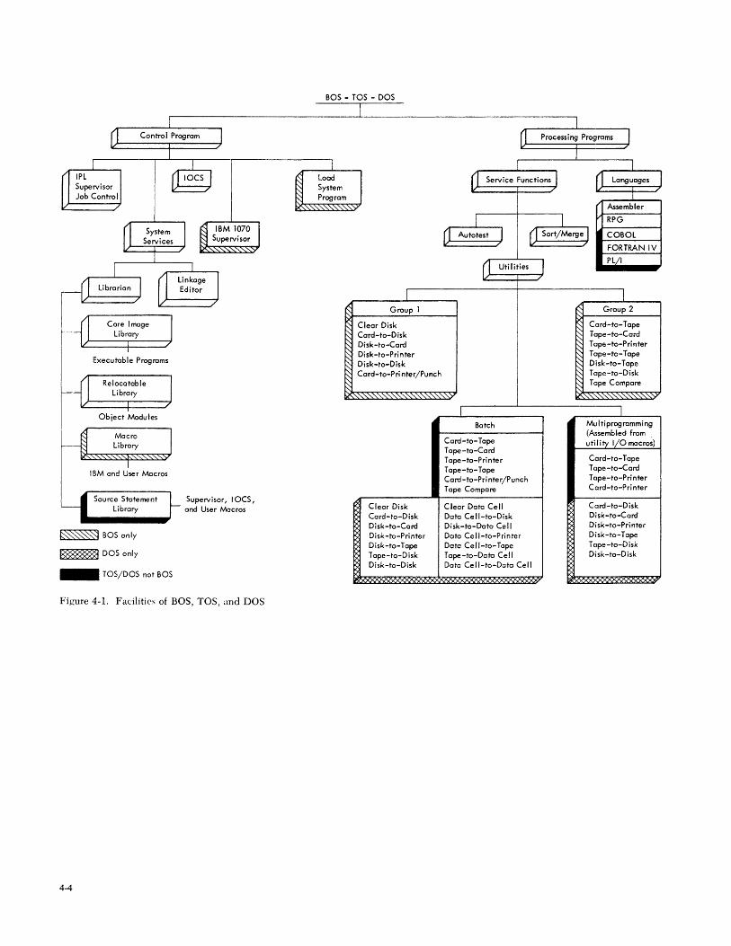
The facilities of BOS, DOS, and TOS are depicted in Figure 4-1. A diagram of OS is available on a card in color~ see Operating System/360 Chart, GV2S-61 S6.
Programming Systems Glossary
Assemble*. To prepare a machine language program from a symbolic language program by substituting absolute operation codes for symbolic operation codes and absolu t'e or relocatable addresses for symbolic addresses.
Assembler*. A program that assembles.
Compile*. To prepare a machine language program from a computer program written in another programming language by making use of the overall logic structure of the program, or generating more than one machine instruction for each symbolic statement, or both, as well as performing the function of an assembler.
Compiler*. A program that compiles.
Initial Program Loader (IPL)*. The procedure that causes the initial part of an operating system or other program to be loaded such that the program can then proceed under its own control.
IOCS. Input/Output Control System.
Ltnkage*. In programming, coding that connects two separately coded routines.
, * American National Standard definition
Linkage Editor. A program that produces a load module by: (1) transforming object modules into a format that is acceptable for execution, (2) combining separately produced object modules and previously processed load modules into a single load module, (3) resolving symbolic cross references among them, (4) replacing, deleting, and adding control sections automatically on request, and (5) providing overlay facilities for modules requesting them.
Load Module. (1) The output of the linkage editor. (2) A program in a format suitable for loading into main storage for execution.
Macro Instruction *. An instruction in a source language that is equivalent to a specified sequence of machine instructions.
Module*. A program unit that is discrete and identifiable with respect to compiling, combining with other units, and loading; for example, the input to, or output from, an assembler, compiler, or linkage editor.
Object Module*. A module that is the output of an assembler or compiler and is input to a linkage editor.
Program Library*. A collection of available computer programs and routines.
System/360 Programming Systems 4-3
BOS - TOS - DOS
I
0 Control Program I n Processing Programs I )
I 1 ) I / IPL (lIOCS J ~ Load 0 Service Functions I 1 Languages
Supervisor ~ System /
Job Control - -~ Program I
~ " " " ',:" " " ""V Assembler
I I RPG
G I ~ IBM 1070 I System (I Autotest J rJ Sort/Merge J COBOL Services Supervisor
/ FORTRAN IV
~"" ."""""..." PLjI
I I (I Utilities
0 Linkage
J /
'I 1 Librarian Editor
I I l/ / ./
~ ~ Group 2 Group 1
'I Core Image
1
~ Clear Disk ~ Card-to-Tape
I Library ~ Card-to-Disk ~ Tape-to-Card ~ ~ V / ~ Disk-to-Card ~
(A~sembled from _ Macro Cord-to-Tape Library uti lity I/O macros) T ope -to-Co rd
1IoC'-" " Tape-to-Printer Cord-to-Tape I Tape -to-Tape T ope -to-Card
IBM and User Macros Card -ta-Pri nter/Punch Tape-ta-Pri nter
T ape Compare Cord-to-Pri nter --I Source Statement Supervisor, 10CS, Library and User Macros Clear Disk Clear Data Cell Card-to-Disk
Cord-ta-Disk Data Cell-ta-Disk Disk-ta-Cord Disk-ta-Cord Disk-ta-Dato Cell Disk-ta-Printer
~~ BOSanly Disk-to-Printer Data Cell-ta-Printer Disk-to-Tape
B8888888 DOS anly Disk-to-Tape Data Cell-ta-Tape Tape-to-Disk T ope-ta-D isk Tape -ta-Do to Ce II Disk-to-Disk Disk-ta-Disk Data Cell-to-Data Cell
TOS/DOS not BOS
Figure 4-1. Facilities of BOS, TOS, and DOS
4-4
Section 5. Teleprocessing, Data Acquisition, and Process Control
Teleprocessing
One of the major considerations in designing System/ 360 was that the system would have to serve as the data processing complex within a larger teleprocessing system. (Figure 5-1)
IBI\r'S past experience with real-time and teleprocessing systems indicated that there are two major differences between teleprocessing systems and the more familiar batch processing systems: batch processing input is scheduled, whereas teleprocessing input is unscheduled; hatch processing is usually serial, whereas teleprocessing is random. To incorporate the ahility to service these two teleprocessing characteristics into a system that would probably be used mostly for batch processing, the System /360 designers had to create new equipment and new programming conventions.
As an example of how a teleprocessing system functions, suppose that a clerk in an insurance company's branch office receives a telephone call asking for in-
formation about an insured's account. Asking the caller to hold the line, the clerk enters the information request into a terminal, and the request is sent over a communications line to the System/:360 at the insurance company's main office. When the request reaches the computer, several things happen. The computer interrupts processing whatever job it is working on (perhaps the payroll is being run) and saves all necessary data and instructions so that ,it can resume processing at exactly the point in the program it had reached before it was interrupted. As the information is received over the communications lines, the communications module in the control program converts the data into machine language, stores it in a buffer area, and checks to see that it was transmitted correctly.
The nature of the request may dictate that a number of diff<,'rent operations must be performed. To process the request, the teleprocessing program directs the System 1360 to nm through the appropriate policy file
.-- ---------------, I I I
I i I I L Data Processing System ---------------
System/360 Central Processing Unit
2701 Data Adapter, 2702 or 2703 Transmission Control, or 3704 or 3705 rommunications Controller
I I I I I I
--------~
Figl\J'c ,'5-1, Syskm/:j(-;O as a Td('pr()c('ssin,!.!; Systcm
Teleproc('ssing, Data Acquisition, and Process Control ,'5-1
and bring the insured's record from storage. The program then searches the record for the information requested and sends it out over the communications lines to the clerk who originated the request. The clerk reads the information as it is typed out at his terminal and relays the information to the policyholder or ad.iuster waiting on the telephone. Back at the main office, the control program has returned the System/ :360 to its status prior to the interruption hy the inquiry, and the computer has resumed proccssing the payroll program.
Requirements of a Teleprocessing System
A careful examination of the preceding cxample reveals that any teleprocessing system must meet certain requirements. System/.360 was designed to respond to all of these requircments without sacrificing its efficient performance of the ordinary batch data processing needs of science and industry.
Transmission Control Capability
The system may be servicing many locations, some on common communications lincs and some on separatc Iincs. Equipment and programming are therefore required to handle the multiple inputs arriving in unscheduled fashion into the System/.360.
Program Switching
On a single transaction, the control program initiates several switches among the various programs; therefore, the processing unit must be designed to accomplish very rapid program switching.
Program Relocation
The processing unit must also have the ability to dynamically relocatc programs in storage during normal processing, because many different types of transactions may necessitate bringing a program from peripheral storage into a location in main storage for which the program was not originally assemhled.
Storage Protection
\Vith multiple programs residing in the system at one time and with constant program sWitching and relocation taking place, it is imperative that there be a facility available that can prevent one program from changing another program's instructions and data.
Transmission Directions and Modes
A communications line (also called a communications channel or circuit) is a path for electrical transmission between two or more terminals. Basically, IBM equipment can operate over three types of circuits: simplex, halfduplex, and duplex (also called full duplex). These circuit names describ(' only directional capability.
5-2
Sim]Jlex Circuits can carry data in only one direction.
11aff-Duplex Circuits can carry data in two directions but in only one direction at a time.
Duplex Circuits can carry data in two directions at the same time .
A network can consist of any combination of these circuits according to application requirements.
Modes
Information can be transmitted over the various types and grades of circuits by three different modes of transmission: 1. Asynchronous Transmission (also called serial start/stop)
requires the use of start and stop bits to deSignate the beginning and ending of characters.
2. Synchronous Transmission eliminates the need for start and stop bits; a special pattern of bits is sent periodically to keep the transmitter and receiver operating in unison. The bit pattern is generated automatically and sent as required by the system.
:3. Parallel Transmission allows all bits of a character to he transmitted simultaneously by providing one circuit for each bit in the code structure.
Most often a user obtains his communications lines from a communications common carrier. The common carrier leases him a private line for his exclusive use or connects him with the telephone network available to the public. A use r can also purchase and maintain his own communications facilities, but these must be purchased from suppliers other than common carriers. There are numerous government regulations concerning the connection of privately owned communications facilities to those owned and maintained by common carriers.
Terminal Connections to Communications Lines
In this System Summary the word "terminal" refers to a machine or group of machines capable of generating and/or receiving signals transmitted over a communications line. Within this definition a terminal may range from a data processing system, such as System/.360, to a single device, such as an IBM 2740 Communication Terminal. One terminal may be connected to another by a point-to-point line or by a multipoint line. A point-to-point (common carrier leased or private) line connects a single terminal to another single terminal, whereas a multipoint line connects more than two
terminals. On circuits with little traffic, the use of a multipoint line often results in a cost saving. Terminals sharing the same line mayor may not have the ability to communicate with each other.
Modems
A modem, also called a data set or line adapter, performs the modulation and demodulation functions necessary to provide compatibility between business machines and communications facilities. Modulation is the conversion of digital signals (from the business machine) to audiofrequency signals for transmission over communication lines. Demodulation reconverts the information for machine use.
Modems may be furnished by communications common carriers, equipment suppliers, or by IBM. Those available as features for some devices are called IBM line adapters.
One modem is required at each interface between the communications facilities and the data processing equipment.
Data Acquisition and Process Control A high-speed data acquisition system is designed to maintain constant communication with a process for such purposes as: l. Determining whether the process is operating with
in acceptable limits. 2. Providing n~cords for accounting or management
decisioris. 3. Providing a record of data obtained during a re
search experiment. A process control system usually incorporates data
acquisition facilities and has the additional capability of using the acquired data as a basis for supervising and controlling the process.
Teleprocessing, Data Acquisition, and Process Control 5-3
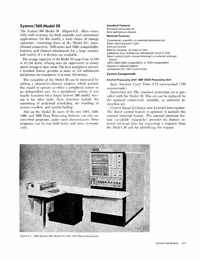
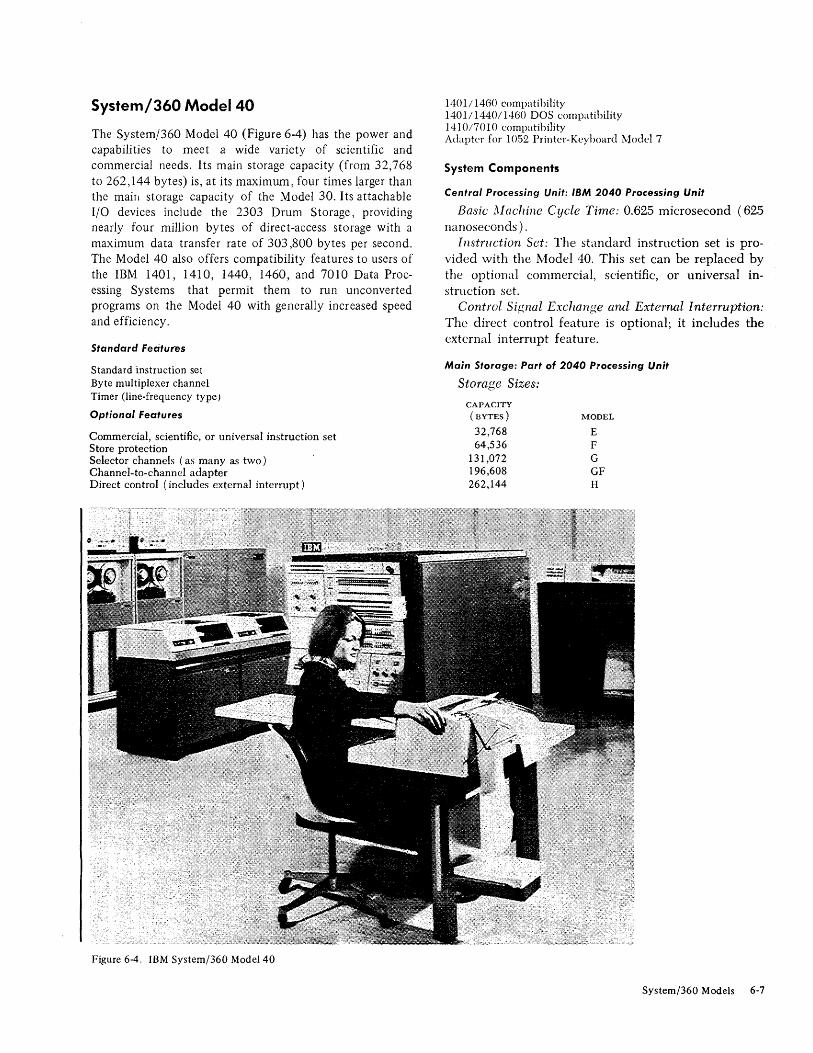
The various models and input/output configurations within the System/360 cover a wide range of commercial and scientific data.handling requirements. Presently, nine models of the System/360 are covered in the System Summary: Models 22, 25, 30,40,50,65,67,75, and 195. In this section, the more prominent features and characteristics of each model are brought together to describe each model individually. Figure 6-9, which compares each model's prominent features and characteristics with those of the other models, appears at the end of this section. The devices that can attach to the individual System/360 models are listed in the next two sections.
System/360 Model 22
The System/360 Model 22 (Figure 6-1) has the power and capabilities to meet a wide variety of scientific and
Figure 6-1. IBM System/360 Model 22
Section 6. System/360 Models
commercial needs at a relatively low cost. Provided either 24K (24,576) bytes or 32K (32,768) bytes of main storage, this model has a selector channel and byte multiplexer channel that allow the attachment of a wide variety of I/O devices. Other features, both standard and optional, further enhance the capabilities of the Model 22.
Standard Features
Standard or commercial instruction set Byte multiplexer channel Selector channel
Optional Features
Scientific or universal instruction set External interrupt Interval timer Storage protection Integrated 1052 attachment
Instrnction Sets: Either the standard or commercial instruction set is provided with the Model 22. Either set can be replaced by the scientific or universal set.
External Interrnption: The external interrupt feature provides six external interruption lines for requesting a response from the Model 22 and for identifying the request.
Main Storage: Part of 2022 Processing Unit
Storage Sizes:
CAPACITY
(BYTES)
24.576 32.768
MODEL
DC E
Storage Cycle Time: 1.5 microseconds.
6-2
Storage Access Width: One byte.
Channels: Part of 2022 Processing Unit
Byte Multiplexer Channel: The byte multiplexer channel provides 96 sub channels and eight control-unit positions.
Selector Channel: The selector channel, which has a data rate of 170,000 bytes per second, uses a microprogram interruption to control data transfers.
Interchannel Connection: The Model 22 can communicate with other models of System/360 by the direct connection of channels, but only if the other model has a channel-to-channel adapter. The adapter requires the use of one control-unit position on each of the two channels.
Programming Support
DOS is the primary programming support for the Model 22. Other existing System/360 applications and programming systems support can be used by the Model 22 within the limitations of storage capacity, channel capability, and CPU features.
System/360 Model 25 Delivering System/360 performance at relatively low cost, the System/360 Model 25 (Figure 6-2) offers features such as main storage capacities of up to 49,152 bytes, channel capabilities, decimal and floating-point arithmetic, and compatibility with the System/360 Model 20 and the IBM 1401, 1440, and 1460 Data Processing Systems.
High performance at minimal cost has been achieved in several ways: by the inclusion of high-speed circuitry for main storage, by the use of microprogramming for emulator and control routines, and by the integrated attachment of the most commonly used I/O devices, in which the normally separate control units are incorporated in the CPU.
Standard features
Commercial instruction set Attachment for 1052 Printer-Keyboard Model 7
Optional features
Scientific or universal instruction set Byte multiplexer channel or selector channel (one of either) Store protection Direct control (with external interrupt) or ex ternal interrupt
(alone) Timer (line-frequency type) 14011 1460 compatibility 14011144011460 DOS compatibility 1440 compatibility System/360 Model 20 mode
Figure 6-2, IBM Systemj360 Model 25 with 1052 Printer-Keyboard
CPU-integrated attachments for: One 140,3 Printer Model 2, 7, or N1 (with multiple character
set adapter) As many as four 2311 Disk Storage Drives Modell (with file
scan feature) One 2540 Card Read Punch Model 1 (with column binary
feature and punch feed read control) One 2560 Multi-function Card Machine Model Al (for
Model 20 mode; also for System/,360 mode [reael/punch only] if the 2540 emulation feature is added)
In(jtruction Set: The commercial instnlction set is provided with the Model 25. This set can be replaced by the optional scientific or universal instruction set.
Control Signal Exchange and External Interruption: The direct control feature is optional; it includes the external interrupt feature.
CPU-Integrated I/O Attachment: The CPU provides for the integrated attachment of a 1052 Printer-Keyhoard Model 7 and the following 1.'0 devices: one 1403 Printer Model 2, 7, or NI, as many as four of the 2311 Disk Storage Drive Modell, one 2540 Card Read Punch Modell, and one 2560 Multi-function Card Machine Model Al. Each of these devices can connect
Systemj360 Models 6-3
to the CPU by means of an appropriate attachment feature and does not require a control unit (2821 or 2841) physically attached to an I/O channel, although to the program the device appears to be on a channel and is addressed accordingly.
In addition to the integrated units, a wide range of other I/O devices is available for attachment to the Model 25 through the use of either a. byte multiplexer or selector channel (both optional). For further details, see Figure 7-1.
CPU-Integrated Communications Attachment: This feature provides teleprocessing entry for Model 25 users through direct attachment of communications lines to a Model 25 rather than through a 2701 Data Adapter Unit or 2702 Transmission Control on a byte multiplexer channel. (See Figure 8-1.)
Main Storage: Part 01 2025 Processing Unit
Storage Sizes: The Model 25 has four possible storage sizes:
CAPACITY
(BYTES)
16,384 24,576 32,768 49,152
MODEL
D DC E ED
Storage Cycle Time: 1.8 microseconds (1,800 nanoseconds). Storage cycle time is the length of time that storage is busy when a reference is made to it.
Storage Access Width: Two bytes (one halfword). Protection Features: Store protection is optional.
Channels: Part 01 2025 Processing Unit
Byte Multiplexer Channel: When the byte multiplexer
channel is operated in byte mode, the I/O devices can operate concurrently with each other, with the integrated devices, and with CPU operations. In burst mode,
6-4
I/O devices can overlap their operations with those of integrated devices but not with CPU operations. With the Model 25, magnetic tape units cannot be used on the byte multiplexer channel.
Selector Channel: This channel can overlap integrated-device and CPU operations and has a maximum data transfer rate of 60,000 bytes per second. The selector channels of Model 25's built prior to February, 1969 have a maximum data rate of 30,000 bytes per second, but will be modified to have the higher data rate.
Interchannel Connection: The Model 25 can communicate with other System/360 models by the direct connection of channels, but only if the other model has a channel-to-channel adapter. The adapter requires the use of one control-unit position on each of the two channels.
System
Compatibility Features: The features that can be installed on the Model 25 are: 1401/1460 compatibility, 1440 compatibility, 1401/1440/1460 DOS compatibility, disk storage operations (for processing 1311 disk information), and System/360 Model 20 mode. The 1401/ 1440/1460 DOS compatibility feature cannot be installed if the Model 25 has either the scientific instruction set or the integrated communications attachment.
System Control: The Model 25 is operated, monitored, and controlled via the system control panel on the 2025 Processing Unit.
Programming Support
The Model 25 can use System/360 application and programming systems support. Existing BPS, BOS, TOS,
and DOS programs apply to the Model 25, within the limitations of the storage capacity and channel capabilities.
System/360 Model 30 The System/360 Model 30 (Figure 6-3) offers versatility with economy for both scientific and commercial applications. On this model, a wide choice of storage capacities (exceeding those of the Model 25), interchannel connection, 1400-series and 1620 compatibility features, and channel attachments for a large number and variety of I/O devices are available.
The storage capacities of the Model 30 range from 16,384 to 65,536 bytes, offering users the opportunity to closely match storage to their needs. The byte multiplexer channel, a standard feature, provides as many as 224 subchannels and permits the attachment of as many I/O devices.
The versatility of the Model 30 can he increased hy adding a channel-to-channel adapter, which permits this model to operate as either a peripheral system or an independent one. As a peripheral system, it can handle functions for a larger System /360 model, freeing it for other tasks; these functions include the smoothing of peak-load scheduling, the handling of system overflow, and system hackup.
Also on the Model 30, users of the IE:'.! 1401, 1440, 1460, and 1620 Data Processing Systems can run unconverted programs; under most circumstances, these programs can be run both faster and more economically.
figure 6-3. IBM System/360 Model 30 with 1052 Printer-Keyboard
Standard Features Standard instruction set Byte multiplexer channel
Optional Features
Commercial, scientific, or universal instruction set Timer (line-lrequency type) Store protection Selector channels. (as many as two) Additional byte multiplexer subchannels (total of 224) Direct control (with external interrupt) or external interrupt
(alone) 1401/1440/1460 compatibility or 1620 compatibility Channel-to-channel adapter Attachment for 1052 Control Unit
Instruction Sct: The standard instruction set is provided with the !vIodel .'30. This set can be replaced by the optional commncial, scientific, or universal instruction set.
Control Signal Exchan,!!.c and External Interruption: The direct control feature is optional; it includes the external interrupt feature. The external interrupt featun: (available separately) provides six distinct external interrupt lines for requesting a response from the \10dd ,30 and for identifying the request.
Systcm/360 Models 6-5
Main Storage: Part of 2030 Processing Unit
Storage Sizes:
CAPACITY
(BYTES) MODEL
16,384 D 24,576 DC 32,768 E 65,536 F
Storage Cycle Time: 1.5 microseconds (2.0 on earlier models).
Storage Access \Vidth: One byte. Protection Features: Store protection is optional;
fetch protection is not a feature for the Model 30.
Channels: Part of 2030 Processing Unit
One byte multiplexer channel is standard on the Model 30, and one to two selector channels are optional. The number of byte multiplexer subchannels varies from 96 to as many as 224 (with the additional byte multiplexer subchannels feature ).
BYTE MULTIPLEXER
SUBCHA:-<KELS
96 224 (optional)
6-6
MODELS
All E,r
Interchannel Connection: One channel-to-channel adapter may be installed on either a byte multiplexer or a selector channel, permitting communication between two channels (on the same system or on different systems). One control-unit position is required on each of the connected channels. A second channel connection can be made with another system if an adapter is installed on the other system.
System
Compatibility Features:
COl\fPA TIBILITY FEATURE
1401/1440/1460 DOS 1401/1460 1440 1620
APPLICABLE MODELS
All but D All All All
InsLaliation of one compatibility feature precludes installation of another.
System Control: The Mode] 30 is operated, monitored, and controlled via the system control panel on the 2030 Processing Unit.
Programming Support
The Model 30 is supported by BPS, BOS, DOS, TOS, and by os with PCP.
System/360 Model 40
The System/360 Model 40 (Figure 6-4) has the power and capabilities to meet a wide variety of scientific and commercial needs. Its main storage capacity (from 32,768 to 262,144 bytes) is, at its maximwn, four times larger than the main storage capacity of the Model 30. Its attachable I/O devices include the 2303 Drum Storage, providing nearly four million bytes of direct-access storage with a maximum data transfer rate of 303,800 bytes per second. The Model 40 also offers compatibility features to users of the IBM 1401, 1410, 1440, 1460, and 7010 Data Processing Systems that permit them to run unconverted programs on the Model 40 with generally increased speed and efficiency.
Standard Features
Standard instruction set Byte multiplexer channel Timer (line-frequency type)
Optional Features
Commercial, scientific, or universal instruction set Store protection Selector channels (as many as two) Channel-to-channel adapter Direct control (includes external interrupt)
Figure 6-4. IBM System/360 Model 40
1401114()0 compatibility 140111440/1460 DOS compatibility 1410/7010 compatibility Adapter for 10.52 Printer-Keyboard Model 7
Instruction Set: The standard instruction set is provided with the i\1odel 40. This set can be replaced by the optional commercial, scientific, or universal instruction set.
Control Signal Exchange awl External Interruption: The direct control feature is optional; it includes the external interrupt feature.
Main Storage: Part of 2040 Processing Unit
Storage Sizes:
CAPACITY
(UYTES) MODEL
32,768 E 64,536 F
131,072 G 196,608 GF 262,144 H
System/360 Models 6-7
Storage Cycle Time: 2.5 microseconds. Storage Access Width: Two bytes (one halfword). Protection Features: Store protection is optional;
fetch protection is not a feature for the Model 40.
Channels: Part 01 2040 Processing Unit
One byte multiplexer channel is standard on the Model 40, and one to two selector channels are optional. Between 32 and 128 byte mutliplexer subchannels are available, depending on which model is used.
BYTE MULTIPLEXER
SUB CHANNELS
32 64
128
MODELS
E F G,GF,H
Interchannel Connection: One channel-to-channel adapter may be installed on a selector channel and attached to either a byte multiplexer or selector channel. It permits communication between channels (on the same system or on different systems). The adapter requires one control-unit
6-8
position on each of the connected channels. A second channel connection can be made with another system if an adapter is installed on the other system.
System
Compatibility Features:
COMPATIBILITY FEATURE
1401/1460 1401/1440/1460 DOS 1401/1440/1460 Relocatable DOS 1410/7010
APPLICABLE MODELS
All All All but E All but E
System Control: The Model 40 is operated, monitored, and controlled via the system control panel on the 2040 Processing Unit.
Programming Support
The Model 40 is supported by BPS, BaS, DOS, TOS,
and as.
System/360 Model 50 The System/360 Model 50 (Figure 6-5) offers a performance significantly greater than that offered by the Model 22, 25,30, or 40. Its advantages include: increased storage speed and access width, the overlapping of channel and CPU activities, added channel options, more main storage, and the use of an optional 2361 Core Storage (referred to as Large-Capacity Storage or LCS).
Storage: The maximum storage capacity of the Model 50 is 524,288 bytes. This storage can be expanded with LCS by 1, 2, 4, 6, or 8 million bytes (in rounded figures).
Speed: The Model 50's four-byte storage access width and 2.0-microsecond storage cycle time make this model much faster in its internal processing speed than either the Model 30 or 40. Also, the overlapping of byte multiplexer channel and CPU operations further increases the speed of system operations.
The channel options permit increased speed and versatility in I/O operations. The use of one to three selector channels permits the operation of an equal number of high-speed I/O devices, and the number of sub channels of the byte multiplexer channel can be increased to operate as many as 256 lower-speed devices.
Compatibility: Compatibility features on the Model 50 allow users of the IBM 1410,7010,7070, and 7074 Data Processing Systems to run current jobs directly on the Model 50 without reprogramming, often with increased speed.
Figure 6-.5. IB'\1 Systcm/.'360 Modd 50 with 10.32 Printcr-J\:cyhoard
Standard Features
Universal instruction set Store protection Byte multiplexer channel Timer (line-freq uency type)
Optional Features
2361 Core Storage (LCS) with attachment Shared LCS Selector channels (as many as three) Additional byte multiplexer subchanncls (total of 256) Channel-to-channeI adap ter Direct control (includes external interrupt) 1410/7010 or 7070/7074 compatibility Adapter for 1052 Printer-Keyboard Model 7
I nstruction Set: The universal instructioll set is a standard feature of the Mode] 50.
Control Signal Interchange and External Interruption: The direct control feature (with the external interrupt feature included) is optional.
System/360 Models 6-9
Main Storage: Part of 2050 Processing Unit; IBM 236' Core Storage Models , and 2 (Optional)
Storage Sizes: CAPACITY
(BYTES)
131,072 262,144 393,216 524.288
~fODEL
G H HG
Storage Cycle Time: 2.0 microseconds. Storage Access Width: Four bytes (one word). Protection Features: Store protection is standard;
fetch protection is not a feature for the :\10del 50. Large-Capacity Storage: The following units of 2.361
Core Storage may he used: one 2361-1 without interleaving but two with it; one to four 2361-2'5 without interleaving hut two or four with it.
Channels: Part of 2050 Processing Unit
One byte multiplexer channel is standard, and one to three selector channels are optional. The byte multiplexer channel has 128 or 256 subchannels (with the additional byte multiplexer subchannels feature).
BYTE ~1UL TIPLEXER
SUBCHANXELS
128 256 (optional)
6·10
:!I.I0DELS
All All but G
Interchannel Connection: One channel-to··channel adapter may be installed on either a byte multiplexer or selector channel, permitting communication between channels (on the same system or on different systems). The adapter requires one control-unit position on each of the connected channels. A second channel connection can be made with another system if an adapter is installed on the other system.
System
Compatibility Features:
COMPATIBILITY FEATURE APPLICABLE MODELS
1410170lO All 7070/7074 All but G
Installation of one feature precludes installation of the other.
System Control: The Model 50 is operated, monitored, and controlled via the system control panel on the 2050 Processing Unit. The operator control section of this panel may be duplicated to provide a remote operator control panel and can be mounted on a 2150 Console or a 22,50 Display Unit ModelL
Programming Support
The Model 50 is supported by BPS, BaS, DOS, TOS,
and as.
System/360 Model 65 The System/360 Model 65 (Figure 6-6) offers powerful performance with exceptional versatiiity in largesystem applications. This is achieved primarily with large storage capacity, high speed, compatibility with a large number of systems, and multiprocessing system capabilities.
The Model 65 has a maximum main storage capacity of 1,024K (1,048,576) bytes in a single-cpu Model 65, and with additional features, 2,048K (2,097,152) bytes in the two-cpu Model 65 Multiprocessing System .. The storage of a single-cpu system can be supplemented by 1,024K to 8,192K (8,388,608) bytes with 2361 Core Storage (LCS). LCS permits access to large blocks of data without the need for time-consuming references to I/O device's, resulting in both increased capacity and speed.
The Model 65's storage accessing, significantly larger and faster than the Model 50's, also increases the speed of operations. Two-way interleaving further increases the speed of operations by substantially reducing the effective access'time.
With the configuration-control panel feature, the multiprocessing (Model 65 MP) system can be formed from two Model 65's operating as a single large-scale system under one control program. The cpu's of each Model 65 are interconnected, and both main storage anJ the I/O devices are shared. Such a system offers several advantages:
1. It balances the workload among the cpu's; main storage units, and the I/O devices to provide more efficient use of these units. Thus the combined system can operate at close to its top theoretical efficiency, adjusting its full resources at any time to match the workload of each cpu.
2. It increases critical system availability, especially desirable in real-time applications. By the use of the configuration control panel, units can be removed from operation and the system reconfigured without them. Also, programs are available that provide error correction capabilities, further increasing system availability.
3. It provides exceptional flexibility. The system can allow each of the two Model 65's to operate as an independent subsystem, each with its own control program and its assigned main storage and I/O
devices.
Standard Features
Universal instruction set Storage protection (both store and fetch protection) Attachment for 2870 Multiplexer Channel Attachment for 2860 Selector Channel Timer (line-frequency type)
Optional features 2361 Core Storage (LCS) with attachment (not available for
Model 65 Multiprocessing System) Shared LCS (not available for Model 65 Multiprocessing Sys
tem) 2860 Selector Channel (providing as many/as six selector channels
per CPU) 2870 Multiplexer Channel (as many as two per CPU) Selector subchannels (as many as four on the first 2870, as
many as two on a second one) Channel-to-channel adapter Direct control (ineludes external interrupt) 7070/7074, 7080, or 709/7040/7044/7090/7094/7094 II com
patibility Adapter for 1052 Printer-Keyboard Model 7 (as many as two) Configuration control panel
System Components Central Processing Unit: IBM 2065 Processing Unit
Protection Features: Both store and fetch protection are standard features.
Large-Capacity Storage (2361 Core Storage): NUMBER OF NUMBER OF
2361-1's 2361-2's Without interleaving lIto 4 0
With interleaving 2 2 to 4 0
01£ the system has two 2860's and two 2870's, then the maximum number of 2361's permitted is three rather than four.
Channels: IBM 2860 Selector Channel Models 1-3 and 2870 Multiplexer Channel
The Model 65 can have as many as seven channels per cpu (one byte multiplexer and six selector or two byte multiplexer and five selector) but requires at least one.
System/360 Models 6-11
Figure 6-6. IBM System/360 Model 65 with 1052 Printer-Keyboard
The 2870 Multiplexer Channel provides the Model 6.5 with subchannels:
BYTE ~!UL TIPLEXER SUBCHAN:\,ELS
First 2870 192 Second 2870 192
°None on any second 2870 of a Model 65 MP.
SELECTOR
SUDCHANNELS
( OPTIONAL)
up to 4 up to 2°
Interchannel Connection: The channel-to-channel adapter is used to interconnect two System/360 channels. On the Model 65, an adapter can be attached for each of the selector channels, permitting each of them to communicate with either a byte multiplexer channel or with another selector channel. The use of an adapter requires one control-unit position on each of the connected channels.
System
Multiprocessing System: The two cpu's of the Model 65 Multiprocessing System share the 2365-13 storage units. Prerequisites of this system are emergency power-off control (on one cpu), the direct contrnl feature, and the configuration control panel.
7070/7074 All 7080 All 70917040170441709417094 II All but H
Only one of these compatibility features (emulators) can be installed on any Model 65 system. For emulation on a Model 6.5 :\1P, the required portions of the system must be partitioned out of the system environment; that is, the cpu with the compatibility feature,
6-12
the appropriate amount of storage, and the required I/O units must be partitioned as a separate system.
System Control: The Model 65 is operated, monitored, and controlled via the system control panel on the 2065 Processing Unit. A remote operator control panel is also available, which can duplicate the operator control section of the system control panel and may be mounted on a 2150 Console or a 2250 Display Unit Model l. The Model 65 MP has, in addition, a configurator control panel which is shared by the two cpu's and which provides for switching among three modes (multisystem, partitioned, and Model 65), manually assigning storage addresses, and switching I/O interfaces on- or off-line.
Programming Support
The :Model 65 is supported by BPS, BOS, DOS, TOS, and os.
For the control program of os, the Model 65 uses the Primary Control Program (pcp), Multiprogramming with a Fixed Number of Tasks (MIT), or Multiprogramming with a Variable Number of Tasks (MVT).
These are discussed in Section 4. With MVT or MIT,
the Model 65 has Recovery Management Support ( RMS) programs; they provide the Model 65 with error-correction capabilities, and thereby minimize the impact of machine malfunctions.
The \10del 65 ~1ultiprocessing System is an integral part of as with :\1V"I'. Any job that operates with MVT
can be processed in the multiprocessing system without changing code, job control language, or data.
System/360 Model 67 Designed primarily for time-sharing applications, the System/360 Model 67 is a unique combination of equipment and advanced programming which provides fast access to this high-performance system from remote terminals.
This model has two basic configurations: the Model 67-1 and the Model 67-2 (Figure 6-7). The Model 67-1 is a one-cpu system with a 2067 Processing Unit Model 1; the Model 67-2 may be a one-cpu (half-duplex) or a two-cpu (duplex) system with one or two 2067-2's, a 2167 Configuration Unit, and a 2846 Channel Controller.
In addition to its time-sharing capability, the Model 67 can economically and efficiently handle huge libraries of data, can be partitioned into separate subsystems for specific jobs, and can work around temporarily disabled components without disturbing critical jobs. These advantages are due in part to the following features and characteristics.
Shared Storage: The duplex 'lodel 67-2 allows shared use of the multiple processor storage units by the two cpu's, making available as many as two million bytes of storage to either unit.
System Partitioning: The duplex model also allows partitioning of the components into separate subsystems for maximum flexibility and availability, achiev-
ing this by controls provided on the IBM 2167 Configuration Unit.
Dynamic Address Translation: This combination of advanced programming and circuitry permits each user to program as though he had sole use of a large, contiguously-addressable main storage area of about 16 million or 4 billion bytes, depending on whether the standard or the extended dynamic address translation feature is chosen. This feature may be turned off to permit use of the Model 67 as a Model 65.
Standard Features, Model 67·J
Universal instruction set Seven-bit storage protect (for the 2067 Processor Unit Modell) Attachment for as many as two 2860 Selector Channels Attachment for one 2870 Multiplexer Channel 24-hit dynamic address translation Timer (high-resolution type)
Standard Features, Model 67-2
Universal instruction set Address prefixing (for the 2067 Processing Unit Model 2) Attachment for the first 2067-2 (for the 2365-12) Shared storage Floating storage addressing (for the 2167 Configuration Unit) Floating channel addressing (for the 2167 Configuration Unit) Seven-bit storage protect (for the 2067-2) Attachment for as many as two 2067 Processing Units Model 2 Attachment for as many as eight units of 2365 Processor Storage
Model 12 (for the 2846) Attachment for a 2846 Channel Controller (one per 2067-2) 24-hit dynamic address translation Partitioning sensing (for the 2167 Configuration Unit) Timer (high-resolution type)
System/360 Models 6-13
Optional Features, Model 67-1
Floating storage addressing High-speed, direct-access storage priority (for the first selector
channel) Expansion feature (for 2365 Processor Storage Model 2) Seven-bit storage protect (for the 2365 Processor Storage Model
2) 2860 Selector Channel (providing as many as six selector channels)
2870 Multiplexer Channel (as many as two) Selector subchannels (as many as four on the first 2870, as
many as two on a second one. Channel-to-channel adapter Direct control (includes external interrupt) 7091704017044170901709417094 II compatibility Extended dynamic address translation Adapter for 1052 Printer-Keyboard Model 7
Optional Features, Model 67-2
Address prefixing (one for each channel on the duplex Model 67-2)
Additional addressing, types I and II (for each 2846 Channel Controller)
High-speed, direct-access storage priority (used only on the first selector channel)
2846 switching feature (as many as two) Expansion feature Power sequencing 2067 switching feature 2860 Selector Channel (as many as two units per 2846) 2870 Multiplexer Channel (one per 2846) Selector subchannels (as many as four) Channel-to-channel adapter Additional attachment for thc 2846 Channel Controller Extended direct control (includes external interrupt) 7091704017044170901709417094 II compatibility Partitioning sensing (for the 2067 Processing Unit Model 2) Extended dynamic address translation Adapter for the 1052 Printer-Keyboard Model 7 Second wall section attachment
System Components
Central Processing Unit: IBM 2067 Processing Unit Models rand 2
One 2067-1 is available with the Model 67-1, but one to two 2067-2's are available with the Model 67-2.
Instruction Set: The universal instruction set is standard with the Model 67.
Control Signal Exchange and External Interruption: The direct control feature is optional on the 'Model 67-1, and the extendpd direct control feature, which permits the direct communication of control information between two cpu's, is used on the duplex Model 67-2. Each cpu in a duplex system must he equipped with this feature. Both control features include the external interrupt feature.
Dynamic Address Translation: This combination of advanced programming and circuitry permits each user to program as though he had soh, usc of a large, contiguously-addressable main storage area of about 16 million or 4 billion bytes, depending on whether the
6·14
standard or the extended dynamic address translation feature is chosen.
Partitioning Sensing: This feature, required on each cpu of a duplex Model 67-2, allows the program to sense the status of all partitioning switches of the 2167 Configuration Unit.
Floating Storage Addressing: This feature provides the Model 67-1 with the capability of changing the addressing of 2365 Processor Storage Model 2's.
Main Storage: IBM 2365 Processor Storage Models 2 and r 2
As many as four 2365-2's are available with the Model 67-1 and as many as eight 2365-12's with the Model 67-2.
Protection Features: Th(' seven-bit storage protect feature expands the standard fetch protection to accommodate the dynamic address translation feature. One such protection feature is required on each 2,365-2; it is standard on the 2365-12.
Shared Storage: The duplex Model 67-2 allows shared use of the multiple processor storage units by the two cpu's, making as many as 2,097,152 bytes of storage available to either unit.
IBM 2 r 67 Configuration Unit
The 2167 Configuration Unit contains: 1. The partitioning switches and lights for the 2067
Processing Unit Model 2's, 2365 Processor Storage Model 12's and 2846 Channel Controllers.
2. The switches for the I/O control units. Included also are the floating addressing controls
(for both channels and storage) and the partitioning sensing feature.
IBM 2846 Channel Controller
This unit (used only with the l\10del 67-2) provides the system \vith increased accessibility to auxiliary storage devices, especially useful in time-sharing applications. In the duplex l\iodel 67-2, it provides: 1. Communication bet\veen the cpu's and the chan
nels controlling the auxiliary storage devices. 2. Data paths for control information and data trans
fers lwtw('cn J1'win storage and the channels.
The basic 2846 allows for the attachment of as many as four units of 2365 Processor Storage Model 12; the additional addressing features (I and II) increase this number to eight, permitting the 2846 to address over 2 million bytes of main storage. Also, as many as two 2846's may be attached to a Model 67-2 permitting as many as 14 channels (12 selector and 2 byte multiplexer) in a system.
Channels: IBM 2860 Selector Channel Models 7·3 and 2870 Multiplexer Channel
The Model 67 can have as many as seven channels per CPU (six selector and one byte multiplexer, or alternatively for the Model 67-1, five selector and two byte multiplexer) but requires at least one channel of either type.
The 2870 Multiplexer Channel provides the Model 67 with subchannels:
First 2870 Second 2870 (on 67-1 only)
BYTE MULTIPLEXER SUBCHANNELS
19~ 192
SELECTOR
SUBCHANNELS
(OPTIONAL)
up to four up to two
With the Model 67-2, one 2846 Channel Controller attachment feature is standard, and a second is optional. Each 2846 can attach one 2870 and two 2860's; at least one 2860 or 2870 is required. Therefore, with two 2846's, two byte multiplexer channels can be available; only one of these channels may have more than eight control units or have selector subchannels. The duplex Model 67-2 also requires the address prefixing feature on each channel.
Interchannel Connections: The channel-to-channel adapter is used to interconnect two System/360 channels. On the Model 67, an adapter can be attached for each of
the selector channels, permitting each of them to communicate with either a byte multiplexer channel or with another selector channel. The use of an adapter requires one control-unit position on each of the connected channels.
System
Compatibility Feature: The 709/7040/7044/7090/ 7094/7094 II compatibility feature may be installed on both the Model 67-1 and the Model 67-2.
System Control: The Model 67 has one system control panel per cpu. Each one provides for the operation, monitoring, and control of the CPU on which it is mounted. A remote operator control panel is also available· for each CPU, and each panel duplicates the cpu-mounted operator controls and may be mounted on a 2150 Console.
Programming Support
The Model 67 can operate in either a standard mode under DOS, TOS, or OS, or a time-sharing mode under the Time-Sharing System (TSS). While operating under TSS, the Model 67 is capable of doing conversationalinteractive computing together with batch processing on a time-shared basis. TSS takes advantage of the capabilities of a multiprocessor system and perfonns dynamic relocation of problem programs by using the dynamic address translation facilities of the 2067 Processing Unit. (See "Dymimic Address Translation" discussed previously in this model description.)
In the conversational-interactive mode, TSS uses a 2741 Communication Terminal as a remote terminal for such operations as one-line program development and testing, problem solving, and data entry and display.
System/360 Models 6-15
System/360 Model 75 The System/360 Model 75 (Figure 6-8) is a significant step higher in efficiency and speed of internal processing than the Model 65. The primary advantages of the Model 75 are: shorter instruction execution times (approximately two times shorter than the Modcl 6.S) and overlapping of processing (two instructions processed concurrently). The Model 75 has a maximum main storage capacity of 1,048,576 bytes, which can be supplemented by an additional one to eight million bytes of 2361 Core Storage (LCS). The effective speed of storage access is increased by the use of two- and fourway interleaving (two-way only for LCS).
Standard Features
Universal instruction set Storage protection (both store and fetch protection) Attachment for 2870 Multiplexer Channel Attachment for 2860 Selector Channel Direct control (includes external interrupt) Timer (line-frequency type)
Optional Features
2361 Core Storage (LCS) with attachment Shared LCS 2RfiD Selector Channel (providing as many as six selector channels) 2870 Multiplexer Channel (as many as two) Selector subchannels (as many as four on the first 2870, as
many as two on a second one) Adapter for 1052 Printer-Keyboard Model 7 (as many as two)
Figure 6-8. IBM System/360 Model 75 with IBM 2150 Console
Protection Features: Both store and fetch 1?rotection are standard on the Model 75.
[..large-Capacity Storage (2361 Core Storage): NUMBER OF NUMBER OF
2361-1's 2361-2's \Vithout interleaving lIto 4° With interleaving 2 2 to 4-
olf the system has two 2860's and two 2870's, the maximum number of 2361's permitted is three rather than four.
Channels: IBM 2860 Selector Channel Models J -3 and 2870 Multiplexer Channel
The Model 75 can have as many as seven channels (six selector and one byte multiplexer, or five selector and two byte multiplexer) but requires at least one.
The 2870 Multiplexer Channel provides the Model 75 with subchannels:
First 2870 Second 2870
BYTE MULTIPLEXER SUB CHANNELS
192 192
SELECTOR
SUBCHANNELS
(OPTIONAL)
up to 4 up to 2
Interchannel Connection: The channel-to-channel adapter is used to interconnect two System/360 channels. On the Model 75, an adapter can be attached for each of the selector channels, permitting each to communicate with
either a byte multiplexer channel or with another selector channel. The use of an adapter requires one control-unit position on each of the connected channels.
System
System Control: The Model 75 is operated, monitored, and controlled via the system control panel on the 2075 Processing Unit. A remote operator control panel is also available which can duplicate the operator control section of the system control panel and may be mounted on a 2150 Console or a 2250 Display U nit Model l.
Programming Support
The Model 75 is supported by BPS, BaS, DOS, TOS,
and as.
System/360 Models 6-17"
System/360 Model 195 The System/360 Model 195 is an ultrahigh-performance data processing system designed for high-speed large-scale scientific and commercial applications. Its scientific applications range from nuclear physics to weather forecasting and theoretical astronomy. In commercial applications, the Model 195 can be used, for example, as the control center of the most complex airline reservation systems, coast-to-coast time-sharing networks, or process control systems.
The power and speed of this advanced system arc primarily the result of:
l. Improved circuit technology. 2. High perfOlmancc of buffer storage for main
storage accesses. :3. Buffering within the processor. 4. Very fast execution times. . 5. A high degree of concurrency in operation. 6. Highly efficient algorithms, particularly in float
ing-point operations. Circuitry: The logic circuits in the i\1odel 195 use
monolithic technology. These advanced circuits have a basic delay time of less than 5 nanoseconds, as compared with delay times of .5 to .30 nanoseconds for SLT
circuits used in most other Systcm l 360 models. Also, the monolithic packaging densities arc many times those of SLT circuitry; hoards approximately 8 by 12 inches contain as many as 4.000 circuits.
Parallel Processing: Processing procceds concurrently in five separate highly autonomous units: main storage, the storage control unit and buffer storage, the instruction processor, the fixed-point/variable-fie1dlength/decimal processor, and the floating-point processor. Furthermore, each unit may be performing several functions at one time. In the floating-point processor, for example, as many as three Roating-point operations may he executed concurrently.
Standard Features
Universal instruction set High-speed buffer storage Extended-precision floating-point Byte-oriented operands Storage protection (both store and fetch protection) Attachment for 2860 Selector Channel Attachment for 2870 Multiplexer Channel Attachment for 2880 Block Multiplexer Channel Direct control (includes external interrupt) Interval timer (9.6 kHZ-about a 104-microsecond interval) System console Remote operator control panel attachment Emergency power-off control
6-18
Optional Features
2860 Selector Channel (providing as many as six selector channels) 2870 Multiplexer Channel (as many as two) Selector subchannels (as many as four on the first 2870, as
many as two on a second one) 2880 Block Multiplexer Channel (providing as many as six
word). Higll-Speed Bllffer Storage: Most storage accesses
are satisfied hy this :32K-byte buffer storage, which in effect reduces the access time of most main storage accesses from 810 nanoseconds to 162. The buffer storage is controlled by an algorithm implemented in monolithic circuitry, thus its function is transparent to the programmer.
Storage Control Unit: This unit is the intermediary hetween main storage and the other system units. As such, it controls the accesses to the high .. speed buffer storage and to main storage.
Channels: IBM 2860 Selector Channel Models J -3, 2870 Multiplexer Channel, and 2880 Block Multiplexer Channel Models 1 and 2
The Model 195 can have as many as seven channels per CPU, contained within three to seven channel units (2860, 2870, and 2880 frames). The maximum combination of channels can be either: 1. One byte multiplexer channel and six selector and/or
block multiplexer channels.
2. Two byte multiplexer channels and five selector and/or block multiplexer channels.
At least one channel is required. If the one channel is a 2870, it must have at least one selector subchannel.
Both the first and second 2870 have 192 byte multiplexer subchannels. The first 2870 can additionally have four selector subchannels, and a second 2870 can have two.
Interchannel Connection: A channel-to-channel adapter can be attached for each selector channel on the Model 195, permitting each selector channel to communicate with a byte or block multiplexer channel or with another selector channel. This adapter uses one control-unit position on each of the two channels.
System
System Control: The system controls are located on a stand-alone system console (considered part of the cpu). Integrated with the system console is a display console (similar to a 2250 Display Unit Modell), which provides the operator with visual two-way communication with the system. The operator controls can also be duplicated at a remote panel on a 2150 Console.
Programming Support
The Model 195 is supported by a subset of as with MVT.
System/360 Models 6-19
Application on Models
Features and Characteristics
f I I I I I I I 22 25 30 40 50 65 67 75 195
Central Processing Unit (CPU)
CPU Model Number 2022 2025 2030 2040 2050 2065 2067 2075 3195
Main Storage Capacities (in BytM) @ (Entries are Model PrefixM or SuffixM)
16,384" 0 0
24,576· DC OC DC DC
32,768" E E
49,152" ED ED 65,536 = F
131,072" G
196,608" GF GF
262,144" H -I, -2
393,216" HG HG
524.288" I I, MP -I, -2
786,432·'H IH,MP -1,-2 IH
1,048,576 = J J,MP -I, -2 J
1.310.720 MP -2
1,572,864 MP -2
1,835,008 MP -2
2,097.152 a K MP -2
3,145,728 = KJ KJ
4,194,304 .. L
Competibility Features (Entries are Model PrefixlS or SulfixM)
1401/1440/1460 DOS DC, E, ED DC,E, F all
1401/1440/1460 ReloCltable DDS all
1401/1460 all all .11 but E
141017010 .11 but E all 1440 all all 1620 all 7070/7074 H,HG,I all
7080 all 7091704017044/709017094 II I,IH,J,MP -I, -2
709170901709417094 II Modll 20 Mode all
Figure 6-9. Comparison of IBM System/360 Models (part 1 of 2)
6-20
Featu res and Characteristics
Programming Support
Basic Operating System (BOS)
Basic Programming System (BPS)
Disk Operating System (oOS)
Operating System (oS)
Tape Operating System (TOS)
Time·Sharing System (TSS)
Channels
Max. No. of Channels per CPU
With extended Channel Feature
Block Multiplexer
With Extended Channel Feature
Byte Multiplexer
Selector
Both Byte and Block Multiplexer
With Extended Channel Feature
Both Byte Multiplexer and Selector
Max. No. of Channel Units (Frames) per CPU
With Extended Channel Feature
2880 Block Multiplexer Channel
With Extended Channel Feature
2870 Multiplexer Channel (Byte Mpx)
2860 Selector Channel
Sub channels 0 (Type and No., Std or Opt)
(n = nonshared, S" shared)
Byte Multiplexer, of lst Byte Mpx Channel
32 n
64 n
96 n
128 n
192 n
224 n
256 n
Byte Multiplexer, of 2nd Byte Mpx Channel
192 n
Block Multiplexer, of Block Mpx Channels
56 n (Max., with 1 s)
64 n (Max., with 0 s)
Selector. of lst Byte Mpx Channel
4 s
8 s
Selector, of 2nd Byte Mpx Channel
2 s
Channel·to·Channel Adapter CD
std .. standard opt .. optional - '" not applicable
Notes:
22 I yes
yes
yes
-yes
-
2
---
1
1
--
2
-
-----
--
all
----
-
--
--
-
-
o Main storage cycle time for some earlier Model 30's is 2.0 microseconds.
25 I yes
yes
yes
-yes
-
1
---
1
1
--
1
-
--
---
all
------
-
--
--
-
-
@ The storage cycle times given for Models 65·195 do not reflect the time reductions that are due to storage interleaving or, additionally for Model 195, the time reduction resulting from the use of the high·speed buffer.
(£) A Model 50 can share LCS with any other Model 50 or with a Model 65 or 75 of equal or larger storage capacity. A Model 65 or 75 can share LCS with any other Model 65 or 75 of equal storage capacity or with a Model 50 with equal or less capacity.
@ The letters shown with the $Iorage capacities are the model prefixes designating these capacities.
30
yes
yes
yes
yes
yes
-
3
---
1
2
--
3
-----
-
-
-all
--
E, F
-
-
--
-
-
-
opt
Figure 6-9. Comparison of IBM System/360 Models (Part 2 of 2)
t
Application on Models
40 I 50 I 65 I 67 I 75 1
195
yes yes yes - yes
yes yes yes - yes .-
yes yes yes yes yes -
yes yel yes yes yes yes
yes yes yes yes yes -- - - yes - .-
3 4 7 7@ 7 7
- - - - - 14
- - - - 6
- - - - - 13
1 1 2 2 2 2
2 3 6 6 6 6
- - - - - 7
- - - .. - 14
3 4 7 7@ 7 7
- - 4 4 4 7
- - - - - 8
- - - - - 6
- - - - - 8
- - 2 2 2 2
- - 2 2 2 6
E - - - - -F - - - - -
- - - - -
G,GF, H all - - - -
- - all -I, -2 all all
- - - - - -- H,I - - - -
- - all -I, -2 all all
- - - - all
- - - - - all
- - all -1 all all
- - - -2 - -
- - H,I,IH,J -1 all all
opt opt opt opt opt opt
o Shared subchannels can control several liO devices or modules having a common control unit; nonshared subchannels can control only one I/O device.
CD For Models 30, 40, and 50, one channel-to·channel adapter may be installed per CPU. For Models 22 and 25, interchannel connection may be made with another system if the adapter is installed on the other system. On Models 65·195, an adapter may be installed for each selector channel installed.
® The Model 67·2 can have as many as 14 channels (12 selector and two byte multiplexer) because it can have two 2846 Channel Controllers, each capable of controlling up to six selector channels and one byte multiplexer channel.
System/360 Models 6-21
A System/360 at any specific installation consists of a central processing unit, main storage, one or more I/O channels, and all online I/O equipment. Online means that the I/O equipment operates under program control. The following I/O devices and control units, arranged by category, can operate online as part of various System/360 models. Attachment information for the current IBM I/O devices and control units is given in the IBM System/360 Input/Output Configurator, GA22-6823.
Direct Access Devices
2301 Drum Storage 2303 Drum Storage 2305 Fixed Head Storage Models 1 and 2 2311 Disk Storage Drive 2312 Disk Storage Model Al 2313 Disk Storage Model Al 2314 Storage Control Models Al and BI 2314 A-Series and B-Series Direct Access Storage Facility 2318 Disk Storage Model Al 2319 Disk Storage Models Bland B2 2321 Data Cell Drive 2820 Storage Control 2835 Storage Control Models 1 and 2 2841 Storage Control 2844 Auxiliary Storage Control 3330 Disk Storage Modell 3333 Disk Storage and Control Modell 3830 Storage Control Models 1 and 2
Display Devices
2250 Display Unit Models I and 3 2840 Display Control Model 2 2260 Display Station Models 1 and 2 2848 Display Control Models 1-3, 21, 22 3272 Control Unit Models 1 and 2 3277 Display Station Models 1 and 2
Magnetic Character Readers
1255 Magnetic Character Reader Models 1-3 1419 Magnetic Character Reader
Magnetic Tape Devices
240 I Magnetic Tape Unit Models 1-6 and 8 2803 Tape Control Models 1,2, and 3 2804 Tape Control Models 1, 2, and 3 2415 Magnetic Tape Unit and Control Models 1-6 2420 Magnetic Tape Unit Models 5 and 7 2816 Switching Unit Modell
Section 7. Input/Output Devices
3410 Magnetic Tape Unit Models 1,2, and 3 3411 Magnetic Tape Unit and Control Models 1, 2, and 3 3420 Magnetic Tape Unit Models 3, 5, and 7 3803 Tape Control Modell
Magnetic Tape Cartridge Devices
2495 Tape Cartridge Reader
Manual Controls
1052 Printer-Keyboard Models 3, 5, 7, and 8 1051 Control Unit Models 1 and N 1
Optical Readers
1231 Optical Mark Page Reader Model N 1 1287 Optical Reader Models 1-5 1288 Optical Page Reader
Printers
1053 Printer Models 1 and 4 1403 Printer Models 2, 7, and N1 1404 Printer Model 2 1443 Printer Model Nl 1445 Printer Model N1 2821 Control Unit Models 1-6 3211 Printer 3811 Printer Control Unit
Punched Card Devic;es
1442 Card Read Punch Model Nl 1442 Card Punch Model N2 2501 Card Reader Models B1 and B2 2520 Card Read Punch Model B 1 2520 Card Punch Models B2 and B3 2540 Card Read Punch 2560 Multi-function Card Machine Model Al 2596 Card Read Punch 3505 Card Reader Models Bland B2 3525 Card Punch Models PI, P2, and P3
Punched Tape Devices
10 17 Paper Tape Reader Models 1 and 2 1018 Paper Tape Punch 2671 Paper Tape Reader 2822 Paper Tape Reader Control 2826 Paper Tape Control Models 1 and 2
Systems
1800 Data Acquisition and Control System 2790 Data Communication System 3270 Information Display System
Input/Output Devices 7-1
The following systems and devices are attachable online to various System/360 models as teleprocessing tenninals. Most are attachable through the 2701 Data Adapter Unit,
I the 2702 or 2703 Transmission Control, or the 3704 or 3705 Communications Controller. Attachment information
I for the systems and devices is given in the IBM System/360 Inpu t /Output Configura tor, GA22-6823. For more infonnation, see IBM Teleprocessing System Summary, GA24-3090, which contains brief descriptions of all IBM teleprocessing terminals, and IBM SRL Bibliography Supplement- Teleprocessing and Data Collection, GA24-3089, which contains a list of the pertinent IBM publications.
2711 Line Adapter Unit 3872 Modem 3875 Modem 4872 Modem Models 1,2, and 3
Keyboard and Terminal Devices
1001 Data Transmission Terminal 1013 Card Transmission Terminal
t A unit locally attached to a System/360 CPU, used to attach various terminals to System/360.
Section 8. Teleprocessing Terminals
1092 Programmed Keyboard Models 1 and 2 1093 Programmed Keyboard Models 1 and 2 2740 Communication Terminal Models 1 and 2 2741 Communication Terminal 2780 Data Transmission Terminal Models 1-4
Display Devices
2260 Display Station Models 1 and 2 2265 Display Station 2845 Display Control 2848 Display Control Models 1,2, and 3 3271 Control Unit Models 1 and 2 3275 Display Station Models 1 and 2 3277 Display Station Models 1 and 2
Audio Communications Devices
7770 Audio Response Unit Model 3t
Data Acquisition and Process Control Systems
1070 Process Communication System 1800 Data Acquisition and Control System
Systems
1030 Data Collection System 1050 Data Communication System 1060 Data Communication System 1130 Computing System 2770 Data Communication SYstem 2790 Data Communication System 3270 Information Display System 3670 Brokerage Communication System 3740 Data Entry System System/3 Models 6,10. and 15 System/7 System/360 Models 20-195
I System/370 Models 115-195
Teleprocessing Terminals 8-1
Where more than one page reference is given, the major reference is first. See the end of the index for machine-numbered units.
machine-check interruptions 2-9 macro instruction 4-3,44 magnetic ink devices 7-1 magnetic tape devices 7-1
X-2
6-4
6-4
main storage comparison for each S/360 model 6-20 features 3-1 in individual S/360 models (see System/360 models) shared 3-1 structure of 2-2
MFT (Multiprogramming with a Fixed Number of Tasks) 4-2
modem in teleprocessing 5-3 modulation 5-3 module
load 4-3 object 4-3, 4-4
multipath control units 2-8 multiplexer (see byte multiplexer) multiprocessing for Model 65 6-11 Multiprogramming 4-2
with a Fixed Number of Tasks (MFT) 4-2 with a Variable Number of Tasks (MVT) 4-2
MVT (Multiprogramming with a Variable Number of Tasks) 4-2
object module 4-3,4-4 on-line I/O devices 7-1 op codes (operation codes) 2-6 operating systems, general facts 4-1 Operating System (OS) 4-2 operation codes (op codes) 2-6 operator controls 2-6 optical readers 7 -1 OS (Operating System) 4-2
packed format (decimal arithmetic) 2-4 parallel transmission in teleprocessing 5-2 parity bit (check bit) 2-1 partitioning
sensing 6-13 system 3-5
PCP (Primary Control Program) 4-2 PL/I 4-1 point-to-point communications lines 5-2 positioning of data 2-3 Primary Control Program (PCP) 4-2 prin ters 7-1 problem programs (processing programs) process control
introduction to 5-3 systems 8-1
processing programs (problem programs) processing units (see CPU's) processor storage 3-1
(see also main storage) processors (see CPU's) program
interruptions 2-8 library 4-3 relocation, in teleprocessing 5-2
program status word (PSW) 2-8
4-2
4-2
programming support for individual S/360 models comparison of 6-20 (see also System/360 models)
Recovery Management Support (see RMS programs) registers 2-4 Report Program Generator (RPG) 4-1 RMS (Recovery Management Support) programs
for Model 65 6-12 RPG (Report Program Generator 4-1 RR instruction format 2-5 RS instruction format 2-5 RX instruction format 2-5
scientific instruction set 3-3 selector
channels 2-7 of specific S/360 models (see System/360 models) 2860 2-7
sub channels 2-7 service programs 4-1 shared main storage 3-1 shared-path control units 2-8 shared sub channels 2-7 SI instruction format 2-6 simplex circuits in teleprocessing 5-2 simulators 3-5 special systems support 4-1 SS instruction format 2-6 standard instruction set 3-3 storage
addressable 2-4 addressing 2-3 buffer 3-4 cycle time 2-4 main (see main storage) protection 3-1
in teleprocessing 5-2 store protection 3-1 supervisor call interruption 2-8 supervisor ttask management) 4-1 sy~tem
control panel 2-6 control section 2-4 generation 4-1 manual control 2-6 partitioning 3-5
System/360 models comparison of 6-20 description of
Model 22 6-1 Model 25 6-3
System/360 models (continued)
Model 30 6-5 Model 40 6-7 Model 50 6-9 Model 65 6-11 Model 67 6-13 Model 75 6-16 Model 195 6-18
System/360 operating systems 4-1
Tape Operating System (TOS) 4-2 task management (supervisor) 4-1 teleprocessing
introduction to 5-1 systems and devices 8-1
terminal connections in teleprocessing multipoint 5-2 point-to-point 5-2
terminals in teleprocessing 8-1, 5-2 time sharing 3-4 Time-Sharing System (TSS) 6-15 timer 3-4 TOS (Tape Operating System) 4-2 translation of characters 2-5 translators 4-1 transmission control devices 8-1 transmission control in teleprocessing 5-2 transmission modes in teleprocessing 5-2 TSS (Time-Sharing SYstem) for Model 67 6-15
universal instruction set 3-3 -utility programs 4-1
word (fullword) 2-1
zoned format (decimal arithmetic) 2-4
2167 Configuration Unit in system partitioning 3-5 in Model 67-2 6-14
2361 Core Storage 3-1 for Model 50 6-10 for Model 65 6-11 for Model 75 6-16
2365 Processor Storage for Model 65 6-11 for Model 67 6-14 for Model 75 6-16
2741 Communication Terminal used with a Model 67-2 6-14 2846 Channel Controller, in Model 67-2 6-14 2860 Selector Channel 2-7 2870 Multiplexer Channel 2-7 2880 Block Multiplexer 2-8
Index X-3
IBM System/360 System Summary Order No. GA22-681 0-12
Your views about this publication mqy help improve its usefulness; this form will be sent to the author's department for appropriate action. Using this form to request system assistance or additional publications, however, will delay response. For more direct handling of such request, please contact your IBM representative or the IBM Branch Office serving your locality.
Possible topics for comment are:
Clarity Accuracy Completeness Organization Index Figures Examples
READER'S COMMENT FORM
Legibility
What is your occupation? _____________________________ _
Number of latest Technical Newsletter (if any) concerning this publication: ____________ _
Please indicate in the space below if you wish a reply.
Thank you for your cooperation. No postage stamp necessary if mailed in the U.S.A. (Elsewhere, an IBM office or representative will be happy to forward your comments.)
GA22-6810-12
Your comments, please ...
This manual is a reference source for systems analysts, programmers and operators of IBM systems. Your comments will help us produce better publications for your use. Each reply will be carefully reviewed by the persons responsible for writing and publishing this material. All comments and suggestions become the property of IBM.
Fold
Fold
~rnlli1 C!)
Business Reply Mail No postage stamp necessary if mailed in U.S.A.
Postage will be paid by:
International Business Machines Corporation Department B98 P.O. Box 390 Poughkeepsie, New York 12602
Fold
FIRST CLASS PERMIT NO. 419
POUGHKEEPSIE, N.Y.
Fold
International Business Machines Corporation Data Processing Division GA22-6810-12 1133 Westchester Avenue, White Plains, New York 10604 (U.S.A. only)
IBM World Trade Corporation 821 United Nations Plaza, New York, New York 10017 (International)
II /1 III ,I I I I
II I
(")
S
I _I
CJ')I -< VI ..... co 3. W 0) o CJ') -< VI ..... co 3 CJ') c: 3 3 Q)
-<
GA22-6810-12
Ltrn~ \!)
International Business Machines Corporation Data Processing Division 1133 Westchester Avenue, White Plains, New York 10604 (U.S.A. only)
IBM World Trade Corporation 821 United Nations Plaza, New York, New York 10017 (International)