860622992 Issue 1, August 2016 www.commscope.com
SYSTIMAX® Ultra-Density Sliding Fiber Shelf
© 2016 CommScope, Inc. All rights reserved
This product is covered by one or more U.S. patents or their foreign equivalents. For patents, see www.commscope.com/ProductPatent/ProductPatent.aspx
Page 1 of 7
General
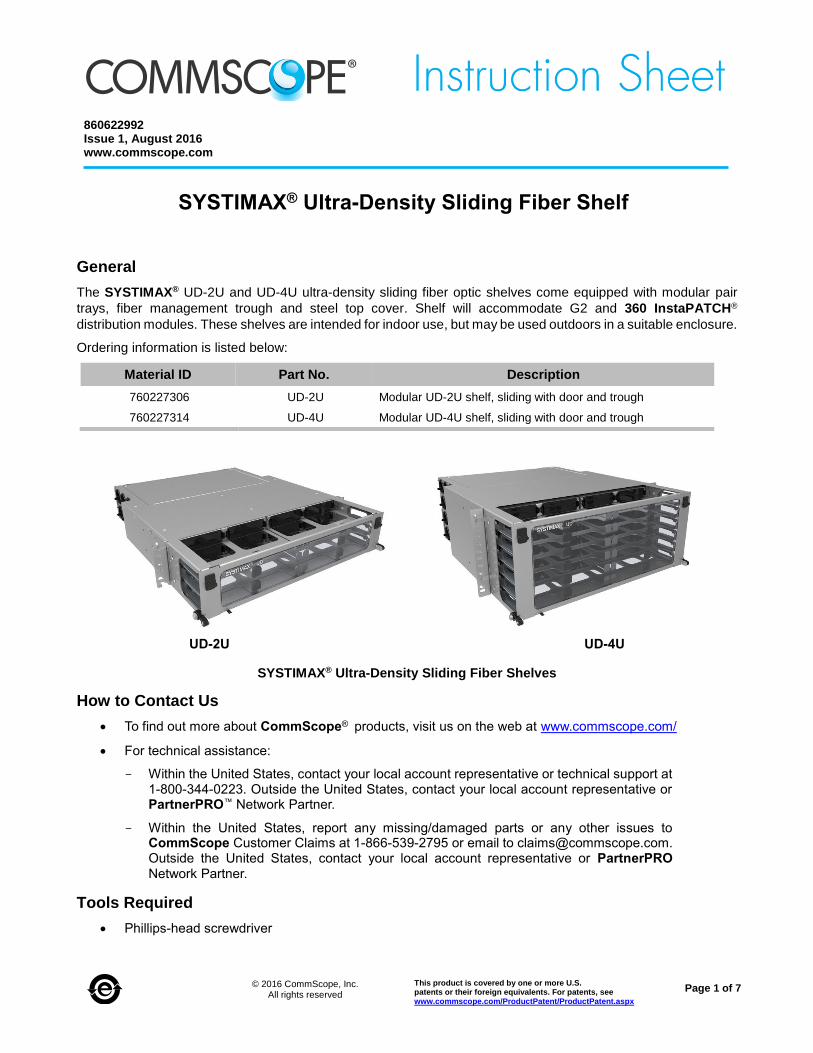
The SYSTIMAX® UD-2U and UD-4U ultra-density sliding fiber optic shelves come equipped with modular pair
trays, fiber management trough and steel top cover. Shelf will accommodate G2 and 360 InstaPATCH®
distribution modules. These shelves are intended for indoor use, but may be used outdoors in a suitable enclosure.
Ordering information is listed below:
Material ID Part No. Description
760227306 UD-2U Modular UD-2U shelf, sliding with door and trough
760227314 UD-4U Modular UD-4U shelf, sliding with door and trough
SYSTIMAX® Ultra-Density Sliding Fiber Shelves
How to Contact Us
To find out more about CommScope® products, visit us on the web at www.commscope.com/
For technical assistance:
- Within the United States, contact your local account representative or technical support at 1-800-344-0223. Outside the United States, contact your local account representative or PartnerPRO™ Network Partner.
- Within the United States, report any missing/damaged parts or any other issues to CommScope Customer Claims at 1-866-539-2795 or email to [email protected]. Outside the United States, contact your local account representative or PartnerPRO Network Partner.
Tools Required
Phillips-head screwdriver
UD-2U UD-4U
860622992 Instruction Sheet
www.commscope.com
Page 2 of 7
Available G2 and 360 InstaPATCH® Modules and Accessories (For Use with Modular Shelf)
Contact your SYSTIMAX sales representative for the latest information on the wide variety of modules and accessories that are compatible with this product, or visit the CommScope website http://www.commscope.com .
Parts List
Verify parts against the parts list below:
Quantity Description
1 Shelf assembly
1 Hook-and-loop strip cable retainer kit
4 #12-24 x 1/2-inch screws for 19-inch (483mm)
4 M6 x 12mm screws for ETSI rack mounting
1 Instruction sheet
Important Safety Cautions
Disconnected optical components may emit invisible optical radiation that can damage your eyes. Never look
directly into an optical component that may have a laser coupled to it. Serious and permanent retinal damage is
possible. If accidental exposure to laser radiation is suspected, consult a physician for an eye examination.
Wearing safety glasses during installation of this shelf is recommended. Although standard safety glasses provide
no protection from potential optical radiation, they offer protection from accidental airborne hardware and cleaning
solvents.
Step 1 – Mount Shelf to Rack
Determine mounting location.
For 19-inch (483mm) rack – Mount shelf to rack using the pre-installed mounting brackets and four #12-24 x 1/2-inch screws (provided) as shown.
!
12-24 mountingscrew (4 places)
RackRear door
Fiber management trough(6 places-2U, 12 places-4U)
Top cover
2U Ultra-density shelf
Trough door
www.commscope.com 860622992 Instruction Sheet
Page 3 of 7
Step 2 – Secure Fiber Cable to Shelf
Note: This shelf is designed for direct connection of fiber cables using cable glands inserted into cable attachment
moldings provided. Another method for securing fiber cables is the use of optional rack mounted brackets, which
is not covered here. See instruction sheet 860380781 for using rack mounted brackets.
Cable Assembly
1. Open rear door.
2. Slide top cover back to remove cover for access to cable routing.
3. Remove cable attachment molding from shelf as shown.
Note: Number of moldings is specific to shelf U size. 2U shelf holds twelve cable attachment moldings and
4U shelf has twenty-four cable attachment moldings.
4. Remove gland nut from cable gland.
5. Slide cable attachment molding onto cable and secure threaded gland nut to hold molding in place as shown.
6. Install assembled cable onto shelf as shown. Snap cable attachment molding back in shelf wall opening.
860622992 Instruction Sheet
www.commscope.com
Page 4 of 7
Step 3 – Route and Secure Trunk Cable
1. Feed cable assembly through cable attachment opening on side of shelf from outside of shelf side wall.
Molding snaps into place and secures trunk cable to shelf, as shown on previous page.
2. Loosely secure trunk cable to equipment rack upright approximately 3 inches (76mm) above or below shelf,
using cable ties. Leave approximately 48-inch (2.1m) length of cable to route into shelf.
3. Fiber cables may enter from right side or left side of shelf.
4. Route subunit cables inside shelf as shown or according to local practices. Secure loose fibers together using
supplied hook-and-loop strip.
Caution: Do not exceed minimum bend radius of fiber. Do not attach fiber bundles to floor of chassis.
5. Fiber cable may be loosely secured to shelf using slots provided along rear of shelf with additional hook-and-
loop strips.
Cablesecuring slots
Hook-and-loop strip
Secure trunk cable
to rail or route into
vertical cable manager
www.commscope.com 860622992 Instruction Sheet
Page 5 of 7
Step 4 – Terminate Fiber Cable Inside Shelf – 360 InstaPATCH®
1. SYSTIMAX UD fiber shelves have two modular pair trays per row. Modular pair trays slide to the front of the shelf separately as shown.
Note: Trays slide until reaching stop to prevent them from sliding out. Do not continue to pull tray past stop.
2. Mount trunk cable to shelf with cable gland, as detailed in Step 3.
3. Install 360 InstaPATCH modules in modular pair trays. Verify that latches on each side of the module snap into tray opening with an audible click.
Note: Remove module with a small flat blade screwdriver used to depress inner-most latch for release from modular pair tray position.
4. Pull subunit cables with MPO connectors through openings in front of shelf and terminate connectors to module.
Step 5 – Remove Trough Door
1. Pull down on both door retaining latches and pull door forward to open trough door.
2. Open door 180° as shown on next page.
3. Remove one hinge from either side of door as shown on the next page, then slide door off opposite side hinge.
4. To re-install door, place door in open position at 180°. Slide door pin on hinge, re-install hinge to pins on trough and secure with screw.
Modular pair
sliding tray
Opened trough door
Installed module
Install module
860622992 Instruction Sheet
www.commscope.com
Page 6 of 7
Step 6 – Install Label on Trough Door
Remove Phillips-head screw,remove hinge
Door retaininglatch
Door hinge
Openedtrough door
Label
trough doorOpened
www.commscope.com 860622992 Instruction Sheet
Page 7 of 7
1. The door may be fitted with labels visible through the door window when closed or may be visible when the
door is open.
2. Open door to 180°.
3. Slide label onto door under clips on door, three on the top and three on bottom of door.
4. Slide label to left or right to secure (depending on label orientation). Note that there are small stops to resist
label sliding past door edge.
Install Label on Trough Door
5. Printable label templates are available on the CommScope® website, which can be used along with available
label stock to create finished port numbering labels.
Note: To print a designation label, go to http://www.commscope.com/Resources/Labeling-Templates,
scroll down to the SYSTIMAX® UD-Density Fiber Shelf and select the appropriate label template.