20
T 4000 series High-Speed, High-Productivity Tapping Center T 4000 series T 4000 T 4000L ver. EN 160502 SU

T 4000 series
High-Speed, High-Productivity Tapping Center
T 4000 seriesT 4000T 4000L
ver. EN 160502 SU

T 4000 seriesDoosan’s T Series is a high-speed tapping center that delivers excellent vastly and productivity. The T Series offers even faster acceleration and greater responsiveness, as well as a greatly improved Z axis for increased productivity. Various accessories and peripheral devices are provided as standard feature, creating added value for users.
T 4000series
02 /
Product Overview
Basic information
Basic Structure
Cutting
Performance
Detailed
Information
Standard/Optional
Specifications
Applications
Diagrams
Machine & NC Unit
Specifications
Customer Support
Service

Sample
High Reliability, Free Of Defects
The new servo-driven T Series, equipped with 21 tools as a standard, offers the highest level of reliability due to improved acceleration and deceleration performance resulting from the optimized spindle length.
NC System with Wide Range of Specifications for Excellent Performance
Fanuc NC eliminate idle time and maximize system productivity.
Enhanced Stability and User Convenience
User convenience has been improved by reducing the machine and table heights and optimizing the center of gravity.
Contents
02 Product Preview
Basic Information
04 Basic Structure09 Cutting Performance
Detailed Information
10 Standard/Optional Specifications
12 Applications13 Diagrams15 Machine & NC Unit Specifications
18 Customer Support
0302 /

High-speed, High-productivity Tapping CenterThe new tapping center delivers best in class productivity by providing superior machining capabilities, a higher feed rate, and a faster tool change time when machining components for the Automotive and IT industries.
Spindle speed 12000 / 24000 r/min
Automatic Tool Changer 21 ea (Servo)
Diversified NC unit specification FANUC CNC
* 48m/min applies to F-31i NC
Description Unit T 4000 T 4000L
Travel distance (X / Y / Z) mm (inch)520 / 400 / 350
(20.5 / 15.7 / 13.8)700 / 400 / 350
(27.6 / 15.7 / 13.8)
Table size mm (inch) 650x400 (25.6x15.7) 850x400 (33.5x15.7)
Load capacity kg (lb) 300 (661.4)
Spindle speed r/min 12000 (24000)
TSC
No. of tool stations ea 21
Rapid traverse m/min 56 56*
NC specification DOOSAN FANUC i series DOOSAN FANUC i seriesFANUC 31i
T 4000series
04 /
Doosan's new tapping center offers improved quality and increased productivity.
Basic StructureProduct Overview
Detailed
Information
Standard/Optional
Specifications
Applications
Diagrams
Machine & NC Unit
Specifications
Basic information
Basic Structure
Cutting
Performance
Customer Support
Service

Reliability Enhanced with a High-rigidity Structural DesignImproved structural design and increased rigidity, realized through FEM analysis, guarantees a stable machining platform.
Optimal Design for the User EnvironmentThe machine's compact design delivers greater user convenience and requires minimal floor space.
Equipment Layout
Specification Unit T 4000 T 4000L
Width mm (inch) 1620 (63.8) 2050 (80.7)
Length mm (inch) 2682 (105.6) 2682 (105.6)
Height mm (inch) 2380 (93.7) 2380 (93.7)
Distance to table mm (inch) 799 (31.5) 799 (31.5)
Height
Width
The systems dynamic rigidity has been enhanced by reducing head weight and modifying the bed and ATC structure.
Enhanced dynamic rigidity against vibration in X/Z directions with improved ATC structure.
Enhanced dynamic rigidity in the X axis by improving the bed structure
Dynamic rigidity in Y axis direction
Previous model
T 4000 / T 4000L
49 %Increase rate
Dynamic rigidity in X axis direction
Previous model
T 4000 / T 4000L
126 %Increase rate
Length
0504 /
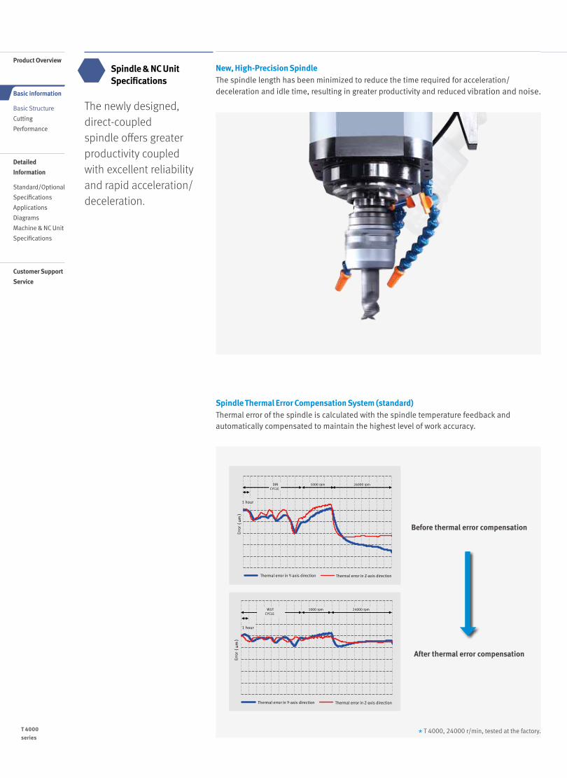
New, High-Precision SpindleThe spindle length has been minimized to reduce the time required for acceleration/deceleration and idle time, resulting in greater productivity and reduced vibration and noise.
Spindle Thermal Error Compensation System (standard)Thermal error of the spindle is calculated with the spindle temperature feedback and automatically compensated to maintain the highest level of work accuracy.
The newly designed, direct-coupled spindle offers greater productivity coupled with excellent reliability and rapid acceleration/deceleration.
Spindle & NC Unit Specifications
Before thermal error compensation
After thermal error compensation
Erro
r(um)
Erro
r(um)
WUT CYCLE
1 hour
DIN CYCLE
1 hour
1000 rpm 1000 rpm 24000 rpm 1000 rpm 24000 rpm
Thermal error in Y-axis direction Thermal error in Z-axis direction Thermal error in Y-axis direction Thermal error in Z-axis direction
Erro
r(um)
Erro
r(um)
WUT CYCLE
1 hour
DIN CYCLE
1 hour
1000 rpm 1000 rpm 24000 rpm 1000 rpm 24000 rpm
Thermal error in Y-axis direction Thermal error in Z-axis direction Thermal error in Y-axis direction Thermal error in Z-axis direction
* T 4000, 24000 r/min, tested at the factory.T 4000series
06 /
Product Overview
Detailed
Information
Standard/Optional
Specifications
Applications
Diagrams
Machine & NC Unit
Specifications
Basic information
Basic Structure
Cutting
Performance
Customer Support
Service
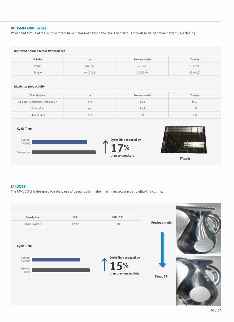
DOOSAN-FANUC i seriesPower and torque of the spindle motor have increased beyond the levels of previous models to deliver more powerful machining.
FANUC 31iThe FANUC 31i is designed to satisfy users' demands for higher machining accuracy and ultra-fine cutting.
IT parts
Previous model
Fanuc 31i
Spindle Unit Previous model T series
Power kW (Hp) 5.5 (7.4) 13 (17.4)
Torque N·m (ft·lbs) 35 (25.8) 83 (61.3)
Improved Spindle Motor Performance
Specification Unit Previous model T series
Spindle Acceleration/Deceleration sec 1.04 0.67
Tool-to-Tool sec 1.48 1.36
Chip-to-Chip sec 2.4 1.8
Description Unit FANUC 31i
Rapid traverse m/min 48
Maximize productivity
Cycle Time
Cycle Time
Competitors
Previous model
T 4000 / T 4000L
T 4000 / T 4000L
Cycle Time reduced by
17%than competitors
Cycle Time reduced by
15%than previous models
0706 /

Magazine Tool MagazineThe servo-motor driven position control system has passed the two-million-cycles test, proving its excellent reliability and durability.
Machine reliability has been improved with the new servo magazine, while productivity has been enhanced by reducing the tool change time. Servo tool magazine
21ea
The new T Series is equipped with a 21 tool servo-driven magazine, replacing the 14-tool magazine of previous models. The new drive system is enclosed for greater oil resistance.
Simultaneous operation control
SpecificationsMax. tool diameter (mm (inch)) Max. tool length
(mm(inch))Max. tool weight
(kg (lb))Continuous Adjacent pots empty
21 tools 80 (3.1) 150 (5.9) 240 (9.4) 2.8 (6.2)
The T Series supports simultaneous X/Y-axis travel during tool change (G100, FANUC), and the axes can be positioned at the next cutting point to minimize idle time.
Closed structureemployed
Servo motor applied
Servo motor
T 4000series
08 /
Product Overview
Detailed
Information
Standard/Optional
Specifications
Applications
Diagrams
Machine & NC Unit
Specifications
Basic information
Basic Structure
Cutting
Performance
Customer Support
Service

Simultaneous operation control
SpecificationsMax. tool diameter (mm (inch)) Max. tool length
(mm(inch))Max. tool weight
(kg (lb))Continuous Adjacent pots empty
21 tools 80 (3.1) 150 (5.9) 240 (9.4) 2.8 (6.2)
Spindle Power – Torque Diagram
Max. spindle speed : 12000 r/min
Spindle Motor : 13 / 7.5 / 5.5 / 3.7 kW
(17.4 / 10.1 / 7.4 / 5.0 Hp)
Max. spindle speed : 24000 r/min
Spindle Motor : 3.7 / 2.2 / 1.1 kW
(5.0 / 3.0 / 1.5 Hp)
Max. spindle speed : 12000 r/min
Spindle Motor : 11 / 7.5 / 5.5 / 3.7 kW
(14.8 / 10.1 / 7.4 / 5.0 Hp)
DOOSAN Fanuc i series
Fanuc 31i DOOSAN FANUC i series Fanuc 31i
3.5 (2.6)
0.4 (0.5)
7.0 (5.2)
0.6 (0.8)
11.8 (8.7)
0.9 (1.2)
0.0
1.5 (2.0)
0.0
Spindle speed (r/min)
Continuous
10min, S3 25%
5min
2.2(10min,S3 25%)
1.1(Cont.)
3.7(5min)
3000 18000 24000
Torque : N·m (ft·lbs) Power : kW (Hp)
Torque : N·m (ft·lbs) Power : kW (Hp)
Torque : N·m (ft·lbs) Power : kW (Hp)
Torque : N·m (ft·lbs) Power : kW (Hp)
35.0 (25.8)
4.4 (5.9)
23.50 (17.3)
2.94 (3.9)
47.7 (35.2)
82.7 (61.0)
6.0 (8.0)8.8 (11.8)
3.7 (5.0)
0.0
7.5 (10.1)
11.0 (14.8)
5.5 (7.4)
Spindle speed (r/min)
Continuous
S3 25%7.5(S3 25%)
3.7(Cont.)
13(S3 15%)
5.5(30min, S3 60%)30min,S3 60%
S3 15%
1500 10000 12000
35.0 (25.8)
4.4 (5.9)
23.50 (17.3)
2.94 (3.9)
47.7 (35.2)
6.0 (8.0)
70.0 (51.7)
7.2 (9.7)
3.7 (5.0)
0.0
7.5 (10.1)
9.0 (12.1)
5.5 (7.4)
Spindle speed (r/min)
Continuous
S3 25%
S3 15%
7.5(S3 25%)
5.5(30min, S3 60%)S3 60%
Continuous
S3 25%
S3 15%
3.7(Cont.)
11(S3 15%)
30min,
1500 10000 12000
8.8 (6.5)
4.0 (5.4)
23.9 (17.6)
9.2 (12.3) 5.0 (6.7)
0.0
11.5 (15.4)
Spindle speed (r/min)
S1: Continuous
Peak, 1min15(Peak, 1min)
5.5(S1: Cont.)
6000 10000 12000
0908 /
Powerful Cutting
Multi-functionality including end milling, face milling, drilling, tapping, etc., enhanced machining performance and minimized work setting.
Cutting Performance
Face mill (Ø63 mm (2.5 inch) Face mill)Tap
40 mm(1.6 inch)
Tool Diameter (mm (inch)) X Pitch (mm (inch))
SM45C GC25 AL6061
DOOSAN FANUC i series (12000 r/min)
M20 (0.8) X 2.5 (0.1)
M24 (0.9) X 3.0 (0.1)
M30 (1.2) X 3.5 (0.1)
Chip Removal Rate (cm3/min) X Spindle Speed (r/min) X Feedrate (mm/min) X Cutting Depth (mm (inch))
SM45C GC25 AL6061
DOOSAN FANUC i series (12000 r/min)
208 X 1500 X 2600 X 2.0 (0.1)
320 X 1500 X 4000 X 2.0(0.1)
684 X 1500 X 5700 X 3.0 (0.1)
* The results, indicated in this catalogue are provides as example. They may not be obtained due to differences in cutting conditions and environmental conditions during measurement.

Diverse optional devices and features available to meet specific customer requirements.
Standard/Optional Specifications ● Standard ◦ Optional X N/A
NO. Description Features F-0i F-31i
1Spindle
12000 r/min ● ◦
2 24000 r/min ◦ ●
3
Spindle motor power
12000_5.5/3.7 kW (7.4/5.0 Hp) ● ◦
4 12000_15/5.5 kW (20.1/7.4 Hp) X X
5 24000_3.7/1.1 kW (5.0/1.5 Hp) ◦ ●
6TSC
NONE ● ●
7 1.5 kW (2.0 Hp)_2.0 MPa ◦ ◦
8
LCD size
8.4 inches ● X
9 10.4 inches ◦ ●
10 12.1 inches X X
11Tool shank type
BIG PLUS BT30 ● ●
12 HSK 63A X X
13 Tool magazine 21 tools ● ●
14 Raised column 150mm (5.9 inch) ◦ ◦
15Hydraulic fixture interface
A/B LINE_1 PAIR ◦ ◦
16 A/B LINE_2 PAIR ◦ ◦
17
Coolant
FLOOD (0.15 MPA) ● ●
18 Flushing ● ●
19 Shower ◦ ◦
20 Coolant gun ◦ ◦
21 OIL SKIMMER Belt type ◦ ◦
22
AIR
Air blower ◦ ◦
23 Air gun ◦ ◦
24 Spindle air curtain ● ●
25
Chip Conveyor
Chip pan ● ●
26 Hinged type ◦ ◦
27 Magnetic scrapper type ◦ ◦
28 Chip bucket Forklift or rotation ◦ ◦
29 Automatic front door Automatic front door ◦ ◦
30 Mist collector ◦ ◦
31 Machine cover type Top cover ● ●
32 Auto tool length measuring device TS27R_RENISHAW ◦ ◦
33Auto tool damage detection device
Needle swing type ◦ ◦
34 Omron limit switch type ◦ ◦
35 Data server DATA SERVER_1GB ◦ ◦
36 Auto power cut-off ◦ ◦
37 Test bar Test bar gauge ◦ ◦
38 Signal tower System condition indicator ● ●T 4000series
10 /
Product Overview
Basic information
Basic Structure
Cutting
Performance
Detailed
Information
Standard/Optional
Specifications
Applications
Diagrams
Machine & NC Unit
Specifications
Customer Support
Service

Diverse Options
Through-spindle coolant system Raised column(150mm)
Auto Tool Measurement DeviceChip box for fine chip disposal
Auto Door Minimum Quantity Lublication Oil SkimmerChip Conveyor
- 4-axis Auxiliary device Interface
- Hydraulic/pneumatic jig line
4-axis Auxiliary device Interface/Hydraulic & Pneumatic Jig Line Checklist for hydraulic/pneumatic lines for work clamping
Number of jig ports1pair (2-PT 1/4" port)2pair (4-PT 3/8" port)3pair (6-PT 1/4" port)
Hydraulic/pneumatic line for jigHydraulic line P/T A/BPneumatic line P/T A/B
Hydraulic unitSupplier : End user
Doosan InfracoreHydraulic unit24 L/min / 4.4 MPA
Customer requirements_______ L/min at _____ MPA
• Please contact us for further detailed specifications.
Pneumatic
Hydraulic
Electronic
Servo drive function & equipment
• T 4000L recommendation
Auxiliary axes controller
1110 /

DOOSAN FANUC i Series familiar to the usersDOOSAN FANUC i
Convenient Fanuc Control
Variable workload control
Instructing M-code equivalent to the weight of the work automatically selects a table transfer pattern appropriate for the weight to be processed.
AICC Higher cutting and feed spindle can be accompanied with unwanted machining error due to high acceleration and deceleration. This function serves to minimize contour deviation of work by controlling servo motor based on block ahead-reading.
FANUC
M-code M384 M380 M381
T 4000 Material weight 0 ~ 130 kg 130 ~ 190 kg 190 ~ 300 kg
T 4000L Material weight 0 ~ 130 kg 130 ~ 190 kg 190 ~ 300 kg
DOOSAN Fanuc i series : AIAPC 20 Block AICC 40 Block AICCⅡ 200 Block
Fanuc 31i : AICCⅡ 200 Block AICCⅡ 600 Block AICCⅡ 1000 Block
User-Friendly Operation Panel
Clamping device lock/unlock button, counter, timer and other special optional buttons are also available.
Buttons are separated by partitions to prevent erroneous operation.
The operation panels are integrated, and customer-tailored function switches ensure convenient system operation.
PCMCIA CardThe PCMCIA card enables uploading and downloading of the NC program, NC parameters, tool information, ladder programs, and also supports DNC operation.
USB PortThe USB memory stick enables uploading and downloading of the NC program, NC parameters, tool information and ladder programs. (DNC operation is not supported.)
124
3
Convenience Functions (Hot Keys)
Frequently used functions can be accessed and used quickly and easily by clicking the hot key buttons.
1 Tapping retract function: A function readily releases tool by reverse rotating the spindle in manual mode when the tool is caught due to a power failure, emergency stop or NC reset.
2 One-touch zero return function: Pressing in manual mode returns the z axis to the primary zero point.
3 ATC position return function: Pressing in manual mode returns the z axis to the secondary zero point, enabling tool magazine rotation.
4 Tool change function: Load and auto-exchange an adjacent tool [Current Tool No. +1] in manual mode.
T 4000series
12 /
Product Overview
Basic information
Basic Structure
Cutting
Performance
Detailed
Information
Standard/Optional
Specifications
Applications
Diagrams
Machine & NC Unit
Specifications
Customer Support
Service

DOOSAN FANUC i Series familiar to the users Dimensions
T 4000
T 4000L
Unit : mm (inch)
Unit : mm (inch)
Top View
Top View
Front View
Front View
1620 (63.8)
320(12.6) (12.6)
980 (38.6) 320
578 (Door)(22.8)
2009
(79.
1)21
89 (8
6.2)
(SH
IPPI
NG
HEI
GHT)
23
80 (9
3.7)
(W/O
TSC
MAX
)24
17 (9
5.2)
(WIT
H TS
C M
AX)
1620 (63.8)
1244
(49.
0)12
80 (5
0.4)
2682
(105
.6)
799
(31.
5)GR
OUN
D TO
TABL
E SU
RFAC
E
(X/2 STROKE) (X/2 STROKE)
1620 (63.8)
320(12.6) (12.6)
980 (38.6) 320
578 (Door)(22.8)
2009
(79.
1)21
89 (8
6.2)
(SH
IPPI
NG
HEI
GHT)
23
80 (9
3.7)
(W/O
TSC
MAX
)24
17 (9
5.2)
(WIT
H TS
C M
AX)
1620 (63.8)
1244
(49.
0)12
80 (5
0.4)
2682
(105
.6)
799
(31.
5)GR
OUN
D TO
TABL
E SU
RFAC
E
(X/2 STROKE) (X/2 STROKE)
1244
(49.
0)12
80 (5
0.4)
2050 (80.7)
793(31.2)
2009
(79.
1)21
89 (8
6.2)
(SH
IPPI
NG
HEI
GHT)
2380
(93.
7) (W
/O TS
C M
AX)
2417
(95.
2) (W
ITH
TSC
MAX
)
799
(31.
5)GR
OUN
D TO
TABL
E SU
RFAC
E
(X/2 STROKE) (X/2 STROKE)
535 (21.1) 535 (21.1)980 (38.6)2050 (80.7)
2682
(105
.6)
(Door)
1244
(49.
0)12
80 (5
0.4)
2050 (80.7)
793(31.2)
2009
(79.
1)21
89 (8
6.2)
(SH
IPPI
NG
HEI
GHT)
2380
(93.
7) (W
/O TS
C M
AX)
2417
(95.
2) (W
ITH
TSC
MAX
)
799
(31.
5)GR
OUN
D TO
TABL
E SU
RFAC
E
(X/2 STROKE) (X/2 STROKE)
535 (21.1) 535 (21.1)980 (38.6)2050 (80.7)
2682
(105
.6)
(Door)
1312 /

T 4000
T 4000L
Unit : mm (inch)
Unit : mm (inch)
Unit : mm (inch)
Table
T-slot Specification / Tool Specification
650 (25.6)325 (12.8) 325 (12.8)
100
(3.9
)100
(3.9
)10
0 (3
.9)1
00 (3
.9)
200
(7.9
)20
0 (7
.9)
400
(15.
7)10
0 (3
.9)1
00 (3
.9)
100
(3.9
)100
(3.9
)20
0 (7
.9)
Detail
200
(7.9
) 400
(15.
7)
Detail
Detail
Detail
850 (33.5)425 (16.7) 425 (16.7)
650 (25.6)325 (12.8) 325 (12.8)
100
(3.9
)100
(3.9
)10
0 (3
.9)1
00 (3
.9)
200
(7.9
)20
0 (7
.9)
400
(15.
7)10
0 (3
.9)1
00 (3
.9)
100
(3.9
)100
(3.9
)20
0 (7
.9)
Detail
200
(7.9
) 400
(15.
7)
Detail
Detail
Detail
850 (33.5)425 (16.7) 425 (16.7)
Detail A
Detail B
22(0.9)
1 12
14 H8
1
9 (0.4)
(0.5
)
(0.6
) (0.6)(0.6)
14 (0
.6)
(0.6
)
(0.6)
(0.5)
(0.1
)14
H8
24 (0
.9)
0.3
3.7
48(1.9) (0.1)(0.8)
.4
Ø 1
2.5H
7
Ø 3
1.7
(1.3
)5
Ø 3
8 (1
.5)
Ø 4
6(1
.8)H
8
Ø 1
1 (0
.4)
Ø 1
6.5
(2.9
)
Ø 7
(0.3
)
Ø 1 (0
.5)2H
7
30˚
Ø 1
6.1H
12
16.3 16.3
13(0.5)
2.5 2.5
23(0.9) (0.8)
5 4
20
3
30˚ 30˚
45˚
24 (0.9)
M12×P1.75M12×P1.75
MAS403-P30T-1(45 )̊
Taper 7/24
7 (0.3)
13.6 (0.5)
17(0.7)
2 200.2
0.1 D1≦ 40mm (1.6)L1≦240mm (9.4)
D2≦ 80mm (3.1)L2≦160mm (6.3)D3≦ 52mm (2.0)L3≦ 34mm (1.3)
L1L2
D2
D1
L3
D3
(0.2)
(0.1) (0.1) (0.1)
(0.2)
Detail A
Detail B
22(0.9)
1 12
14 H8
1
9 (0.4)
(0.5
)
(0.6
) (0.6)(0.6)
14 (0
.6)
(0.6
)
(0.6)
(0.5)
(0.1
)14
H8
24 (0
.9)
0.3
3.7
48(1.9) (0.1)(0.8)
.4
Ø 1
2.5H
7
Ø 3
1.7
(1.3
)5
Ø 3
8 (1
.5)
Ø 4
6(1
.8)H
8
Ø 1
1 (0
.4)
Ø 1
6.5
(2.9
)
Ø 7
(0.3
)
Ø 1 (0
.5)2H
7
30˚
Ø 1
6.1H
12
16.3 16.3
13(0.5)
2.5 2.5
23(0.9) (0.8)
5 4
20
3
30˚ 30˚
45˚
24 (0.9)
M12×P1.75M12×P1.75
MAS405-P30T-1(45 )̊
Taper 7/24
7 (0.3)
13.6 (0.5)
17(0.7)
2 200.2
0.1 D1≦ 40mm (1.6)L1≦240mm (9.4)
D2≦ 80mm (3.1)L2≦160mm (6.3)D3≦ 52mm (2.0)L3≦ 34mm (1.3)
L1L2
D2
D1
L3
D3
(0.2)
(0.1) (0.1) (0.1)
(0.2)
T 4000series
14 /
Product Overview
Basic information
Basic Structure
Cutting
Performance
Detailed
Information
Standard/Optional
Specifications
Applications
Diagrams
Machine & NC Unit
Specifications
Customer Support
Service

1514 /
T 4000 series
{ } : Optional * G 100 function applied
Specification Unit T 4000 T 4000L
F-0i F-0i F-31i
Travel
Travel distance
X-axismm
(inch)520 (20.5) 700 (27.6)
Y-axismm
(inch)400 (15.7)
Z-axismm
(inch)350 (13.8)
Distance from spindle center to table top
mm (inch) 150 ~ 500 (5.9 ~ 19.7)
Distance from spindle center to column
mm (inch) 443 (17.4)
Feed rate
Rapid Transfer Rate
X-axis m/min 56 56 48
Y-axis m/min 56 56 48
Z-axis m/min 56 56 48
Max. cutting feedrate m/min 28 28 24
Table
Table size mm (inch) 650 X 400 (25.6 X 15.7) 850 X 400 (33.5 X 15.7)
Loading capacity kg (lb) 300 (661.4)
Table type T-SLOT (3-100 X 14H8)
Spindle
Max. Spindle Speed r/min12000
{24000}12000 24000 {12000}
Spindle taper ISO #30, 7/24 TAPER
Max. spindle torqueN·m
(ft·lbs)
82.7 (182.3)(S3 15%) {11.8 (26.0)
(5 min)}
82.7 (182.3)(S3 15%)
11.8 (26.0)(5 min)
{70 (154.3)(S3 15%)}
ATC
Tool shank type MAS403 BT 30 / MAS403 P30T-1 45deg
Tool storage capacity ea 21
Max. tool diameter
Continuous mm (inch) 80 (3.1)
Near port empty mm (inch) 150 (5.9)
Max. tool length mm (inch) 240 (9.4) (Tool diameter ≦ 40 (1.6))
Max. tool weight kg (lb) 2.8 (6.2)
Max. tool weight kg (lb) 33 (72.8)
Max. magazine eccentric load weight
kg (lb) 21 (46.3)
Tool selection FIXED ADDRESS
Tool change time (tool to tool)
s 1.3 1.3
Tool change time (chip-to-chip)
s 1.8 1.8*
Motor
Spindle motor powerkW
(Hp)
13 (17.4) (S3 15%) / 7.5 (10.1) (S3 25%) /
5.5 (7.4) (30 min) / 3.7 (5.0) (Cont.)
{3.7 (5.0) (5 min) /2.2 (3.0)
(10 min) / 1.1 (1.5) (Cont.)}
13 (17.4) (S3 15%) / 7.5 (10.1) (S3 25%) /
5.5 (7.4) (30min.) / 3.7 (5.0) (Cont.)
3.7 (5.0) (5 min) / 2.2 (3.0)
(10 min) / 1.1 (Cont.){11 (1.5)
(S3 15%) / 7.5 (10.1) (S3 25%) /
5.5 (7.4) (30 min) / 3.7 (5.0) (Cont.)}
Coolant pump motor powerkW
(Hp)FLOOD : 0.4 (0.5) BASE COOLANT : 0.9 (1.2)
Power Source
Electric power kVA 19 {15.7} 19 17.5 {20.8}
Power Source Mpa 0.54
Dimensions
Height mm (inch) 2380 (93.7)
Length mm (inch) 2682 (105.6)
Width mm (inch) 1620 (63.8) 2050 (80.7)
Weight kg (lb) 2400 (5291.0) 2500 (5511.5)
Machine Specifications

NC Unit Specifications
Item Spec.T 4000 / L
F-0i F-31i
Control Axes
Controlled axes 3 ( X, Y, Z ) X, Y, Z X, Y, Z
Additional controlled axes 5 axes in total ◦ ◦
Least command increment 0.001 mm / 0.0001" ● ●
Least input increment 0.001 mm / 0.0001" ● ●
Interpolation type pitch error compensation - ◦
Interpolation & Feed Function
2nd reference point return G30 ● ●
3rd / 4th reference return ● ◦
Inverse time feed ● ◦
Cylinderical interpolation G07.1 ● ◦
Helical interpolation B Only Fanuc 30i - -
Smooth interpolation - ◦
NURBS interpolation - ◦
Involute interpolation - ◦
Helical involute interpolation - ◦
Bell-type acceleration/deceleration before look ahead interpolation
◦ ◦
Smooth backlash compensation ◦ ●
Automatic corner override G62 ● ◦
Manual handle feed Max. 3unit 1 unit 1 unit
Manual handle feed rate x1, x10, x100 (per pulse) ● ●
Handle interruption ● ◦
Manual handle retrace ◦ ◦
Manual handle feed 2/3 unit - ◦
Nano smoothing AI contour control II is required. ◦ ◦
AI APC 20 BLOCK ● X
AICC I 30 BLOCK - X
AICC I 40 BLOCK ◦ -
AICC II 200 BLOCK ◦ ●
AICC II 400 BLOCK - ◦
High-speed processing 600 BLOCK - ◦
Look-ahead blocks expansion 1000 BLOCK - ◦
DSQ IAICC II (200block) + Machining condition selection function
- -
DSQ IIAICC II (200block) + Machining condition selection function + Data server(1GB)
- -
DSQ IIIAICC II with high speed processing (600block) + Machining condition selection function + Data server(1GB)
- -
Spindle & M-code Functions
M- code function ● ●
Retraction for rigid tapping ● ●
Rigid tapping G84, G74 ● ●
ToolFunction
Number of tool offsets 64 ea - 64 ea
Number of tool offsets 99 ea - ◦
Number of tool offsets 200 ea - ◦
Number of tool offsets 400 ea 400 ea ◦
Number of tool offsets 499 / 999 / 2000 ea - ◦
Tool nose radius compensation G40, G41, G42 ● ●
Tool length compensation G43, G44, G49 ● ●
Tool life management ● ●
Addition of tool pairs for tool life management ● ◦
Tool offset G45 - G48 ● ◦
Programming and Editing Function
Custom macro ● ●
Macro executor ◦ ◦
Extended part program editing ● ●
Part program storage 256KB(640m) - 640m
Part program storage 512KB(1,280m) 1280m ◦
FANUC
● Standard ◦ Optional X Not applicable
T 4000series
16 /
Product Overview
Basic information
Basic Structure
Cutting
Performance
Detailed
Information
Standard/Optional
Specifications
Applications
Diagrams
Machine & NC Unit
Specifications
Customer Support
Service

Item Spec.T 4000 / L
F-0i F-31i
Programming and Editing Function
Part program storage 1MB(2,560m) - ◦
Part program storage 2MB(5,120m) ◦ ◦
Part program storage 4MB(1,0240m) - ◦
Part program storage 8MB(2,0480m) - ◦
Inch/metric conversion G20 / G21 ● ●
Number of Registered programs 400 ea 400 ea -
Number of Registered programs 500 ea - 500 ea
Number of Registered programs 1000 ea - ◦
Number of Registered programs 4000 ea - ◦
Optional block skip 9 BLOCK ● ◦
Optional stop M01 ● ●
Program file name 32 characters - ●
Program number O4-digits ● -
Playback function ● ◦
Addition of workpiece coordinate system G54.1 P1 - 48 (48 pairs) 48 pairs 48 pairs
Addition of workpiece coordinate system G54.1 P1 - 300 (300 pairs) - ◦
OTHERS FUNCTIONS(Operation, setting & Display, etc)
Embeded Ethernet ● ●
Graphic display Tool path drawing ● ●
Loadmeter display ● ●
Memory card interface ● ●
USB memory interface Only Data Read & Write ● ●
Operation history display ● ●
DNC operation with memory card ● ●
Optional angle chamfering / corner R ● ●
Run hour and part number display ● ●
High speed skip function ● ◦
Polar coordinate command G15 / G16 ● ◦
Polar coordinate interpolation G12.1 / G13.1 - ◦
Programmable mirror image G50.1 / G51.1 ● ◦
Scaling G50, G51 ● ◦
Single direction positioning G60 ● ◦
Pattern data input ● ◦
Jerk control AI contour control II is required. ◦ ◦
Fast Data server with1GB PCMCIA card ◦ ◦
Fast Ethernet ◦ ◦
3-dimensional coordinate conversion - ◦
3-dimensional tool compensation - ◦
Figure copying G72.1, G72.2 - ◦
Machining time stamp function - ◦
EZ Guide I with 10.4" Color TFT
Doosan infracore Conversational Programming Solution -.When the EZ Guide i is used, the Dynamic graphic display cannot application
◦ ◦
Dynamic graphic display (with 10.4" Color TFT LCD)
Machining profile drawing. -.When the EZ Guide i is used, the Dynamic graphic display cannot application
◦ ◦
Item Spec.T 4000 / L
F-0i F-31i
Control Axes
Controlled axes 3 ( X, Y, Z ) X, Y, Z X, Y, Z
Additional controlled axes 5 axes in total ◦ ◦
Least command increment 0.001 mm / 0.0001" ● ●
Least input increment 0.001 mm / 0.0001" ● ●
Interpolation type pitch error compensation - ◦
Interpolation & Feed Function
2nd reference point return G30 ● ●
3rd / 4th reference return ● ◦
Inverse time feed ● ◦
Cylinderical interpolation G07.1 ● ◦
Helical interpolation B Only Fanuc 30i - -
Smooth interpolation - ◦
NURBS interpolation - ◦
Involute interpolation - ◦
Helical involute interpolation - ◦
Bell-type acceleration/deceleration before look ahead interpolation
◦ ◦
Smooth backlash compensation ◦ ●
Automatic corner override G62 ● ◦
Manual handle feed Max. 3unit 1 unit 1 unit
Manual handle feed rate x1, x10, x100 (per pulse) ● ●
Handle interruption ● ◦
Manual handle retrace ◦ ◦
Manual handle feed 2/3 unit - ◦
Nano smoothing AI contour control II is required. ◦ ◦
AI APC 20 BLOCK ● X
AICC I 30 BLOCK - X
AICC I 40 BLOCK ◦ -
AICC II 200 BLOCK ◦ ●
AICC II 400 BLOCK - ◦
High-speed processing 600 BLOCK - ◦
Look-ahead blocks expansion 1000 BLOCK - ◦
DSQ IAICC II (200block) + Machining condition selection function
- -
DSQ IIAICC II (200block) + Machining condition selection function + Data server(1GB)
- -
DSQ IIIAICC II with high speed processing (600block) + Machining condition selection function + Data server(1GB)
- -
Spindle & M-code Functions
M- code function ● ●
Retraction for rigid tapping ● ●
Rigid tapping G84, G74 ● ●
ToolFunction
Number of tool offsets 64 ea - 64 ea
Number of tool offsets 99 ea - ◦
Number of tool offsets 200 ea - ◦
Number of tool offsets 400 ea 400 ea ◦
Number of tool offsets 499 / 999 / 2000 ea - ◦
Tool nose radius compensation G40, G41, G42 ● ●
Tool length compensation G43, G44, G49 ● ●
Tool life management ● ●
Addition of tool pairs for tool life management ● ◦
Tool offset G45 - G48 ● ◦
Programming and Editing Function
Custom macro ● ●
Macro executor ◦ ◦
Extended part program editing ● ●
Part program storage 256KB(640m) - 640m
Part program storage 512KB(1,280m) 1280m ◦
1716 /

T 4000series
18 /
Product Overview
Detailed
Information
Standard/Optional
Specifications
Applications
Diagrams
Machine & NC Unit
Specifications
Basic information
Basic Structure
Cutting
Performance
Customer Support
Service
Responding to Customers Anytime, Anywhere
Global Service Support Network
Technical Center: Sales Support, Service Support, Parts Support
5Corporations
3Factories
18Technical Centers
122Dealer Networks
AMERICA EUROPE

- On site service- Machine installation and testing- Scheduled preventive maintenance- Machine repair
Field Services
- Supports machining methods and technology
- Responds to technical queries- Provides technical consultancy
Technical Support
- Programming / machine setup and operation
- Electrical and mechanical maintenance
- Applications engineering
Training
- Supplying a wide range of original Doosan spare parts
- Parts repair service
Supplying Parts
We help customers to achieve success by providing a variety of professional services from pre-sales consultancy to post-sales support.
Customer Support Service
1918 /
Doosan Machine Tools’ Global Network, Responding to Customer’s Needs nearby, Anytime, AnywhereDoosan machine tools provides a system-based professional support service before and after the machine tool sale by responding quickly and efficiently to customers’ demands.By supplying spare parts, product training, field service and technical support, we can provide top class support to our customers around the world.
Domestic Service Support Network
2Integrated Support Centers 7
Sales Branch Offices
6Post-Sales Service Centers 31
Designated Repair Service Centers
CHINA (Yantai)
CHINA (Shanghai)
INDIA
Changwon FactoryHead Office
JAPAN

Major Specifications
T 4000 series Description Unit T 4000 T 4000L
Travel distance (X / Y / Z) mm (inch) 520 / 400 / 350 (20.5 / 15.7 / 13.8) 700 / 400 / 350 (27.6 / 15.7 / 13.8)
Tool taper taper 30 30
Table size mm (inch) 650 x 400 (25.6x 15.7) 850 x 400 (33.5x 15.7)
Max. spindle speed kr/min 12000 12000
Max. spindle motor power kW (Hp) 13 (17.4) 13 (17.4)
Tool storage capacity ea 21 21
NC system - FANUC FANUC
Doosan Machine Tools
Head OfficeYeonkang Bldg., 6th FL., 270, Yeonji-dong,
Jongno-gu, Seoul, Korea
Tel +82-2-3670-5345 / 5362
Fax +82-2-3670-5382
Doosan Machine Tools America19A Chapin Rd., Pine Brook, NJ 07058, U.S.A.
Tel +1-973-618-2500
Fax +1-973-618-2501
http://www.doosanmachinetools.com www.facebook.com/doosanmachinetools
Doosan Machine Tools ChinaRoom 101,201,301, Building 39 Xinzhuan Highway
No.258 Songjiang District,China Shanghai(201612)
Tel +86 21-5445-1155
Fax +86 21-6405-1472
Doosan Machine Tools EuropeEmdener Strasse 24, D-41540 Dormagen, Germany
Tel +49-2133-5067-100
Fax +49-2133-5067-001
Doosan Machine Tools Japan#2412, Mita Kokusai Bldg. 1-4-28 Mita,
Minato-ku, Tokyo 108-0073, Japan
Tel +81 3 5730 9013
Fax +81 3 5730 9016
Doosan Machine Tools India106 / 10-11-12, Amruthahalli, Byatarayanapura,
Bellary road, Bangalore-560 092, India
Tel +91-80-4266-0122 / 121 / 100
* For more details, please contact Doosan Machine Tools.* The specifications and information above-mentioned may be changed without prior notice.* Doosan Machine Tools Co., Ltd. is a subsidiary of MBK Partners, a Korean private equity firm. The trademark is used under a licensing
agreement with Doosan Corporation, the registered trademark holder.


