» Zone Offroad Products • 491 W. Garfield Ave., Coldwater, MI 49036 • 888.998.ZONE • www.zoneoffroad.COM Read and understand all instructions and warnings prior to installation of product and operation of vehicle. Zone Offroad Products recommends this system be installed by a professional technician. In addition to these instructions, profes- sional knowledge of disassembly/ reassembly procedures and post installation checks must be known. Minimum tool requirements include the following: Assorted metric and standard wrenches, hammer, hydraulic floor jack and a set of jack stands. See the "Special Tools Required" section for additional tools needed to complete this installation properly and safely. » PRODUCT SAFETY WARNING Certain Zone Suspension Products are intended to improve off-road performance. Modifying your vehicle for off-road use may result in the vehicle handling differently than a factory equipped vehicle. Extreme care must be used to prevent loss of control or vehicle rollover. Failure to drive your modified vehicle safely may result in serious injury or death. Zone Offroad Products does not recom- mend the combined use of suspension lifts, body lifts, or other lifting devices. You should never operate your modified vehicle under the influence of alcohol or drugs. Always drive your modified vehicle at reduced speeds to ensure your ability to control your vehicle under all driving conditions. Always wear your seat belt. » TECHNICAL SUPPORT www.zoneoffroad.com may have additional information about this product including the lat- est instructions, videos, photos, etc. Send an e-mail to [email protected]detailing your issue for a quick response. 888.998.ZONE Call to speak directly with Zone tech support. » PRE-INSTALLATION NOTES 1. Special literature required: OE Service Manual for model/year of vehicle. Refer to manual for proper disassembly/reassembly procedures of OE and related components. 2. Adhere to recommendations when replacement fasteners, retainers and keepers are called out in the OE manual. 3. Larger rim and tire combinations may increase leverage on suspension, steering, and related components. When selecting combinations larger than OE, consider the additional stress you could be inducing on the OE and related components. 4. Post suspension system vehicles may experience drive line vibrations. Angles may require tuning, slider on shaft may require re- placement, shafts may need to be lengthened or trued, and U-joints may need to be replaced. 5. Secure and properly block vehicle prior to installation of Zone Offroad Products. Always wear safety glasses when using power tools. 6. If installation is to be performed without a hoist, Zone Offroad Products recommends rear alterations first. 7. Due to payload options and initial ride height variances, the amount of lift is a base Figure. Final ride height dimensions may vary in accordance to original vehicle attitude. Always measure the attitude prior to beginning installation. rev032117 T2502 Installation Instructions 2007-2017 Toyota Tundra 4wd 5" Suspension System Difficulty Level easy 1 2 3 4 5 difficult Estimated installation: 8 hours Special Tools Required -Reciprocating Saw or Equivalent -Welder Tire/Wheel Fitment Tire: 35 x 12.50 Wheel: 18x9 w/ 5.5" BS 20x9 w/5.5-6.25" BS
Transcript
»Zone Offroad Products • 491 W. Garfield Ave., Coldwater, MI 49036 • 888.998.ZONE • www.zoneoffroad.com
Read and understand all instructions and warnings prior to installation of product and operation of vehicle.Zone Offroad Products recommends this system be installed by a professional technician. In addition to these instructions, profes-sional knowledge of disassembly/ reassembly procedures and post installation checks must be known. Minimum tool requirements include the following: Assorted metric and standard wrenches, hammer, hydraulic floor jack and a set of jack stands. See the "Special Tools Required" section for additional tools needed to complete this installation properly and safely.
»Product Safety Warning
Certain Zone Suspension Products are intended to improve off-road performance. Modifying your vehicle for off-road use may result in the vehicle handling differently than a factory equipped vehicle. Extreme care must be used to prevent loss of control or vehicle rollover. Failure to drive your modified vehicle safely may result in serious injury or death. Zone Offroad Products does not recom-mend the combined use of suspension lifts, body lifts, or other lifting devices.
You should never operate your modified vehicle under the influence of alcohol or drugs. Always drive your modified vehicle at reduced speeds to ensure your ability to control your vehicle under all driving conditions. Always wear your seat belt.
»technical SuPPort
www.zoneoffroad.com may have additional information about this product including the lat-est instructions, videos, photos, etc.
Send an e-mail to [email protected] detailing your issue for a quick response.
888.998.ZONE Call to speak directly with Zone tech support.
»Pre-inStallation noteS
1. Special literature required: OE Service Manual for model/year of vehicle. Refer to manual for proper disassembly/reassembly procedures of OE and related components.
2. Adhere to recommendations when replacement fasteners, retainers and keepers are called out in the OE manual.
3. Larger rim and tire combinations may increase leverage on suspension, steering, and related components. When selecting combinations larger than OE, consider the additional stress you could be inducing on the OE and related components.
4. Post suspension system vehicles may experience drive line vibrations. Angles may require tuning, slider on shaft may require re-placement, shafts may need to be lengthened or trued, and U-joints may need to be replaced.
5. Secure and properly block vehicle prior to installation of Zone Offroad Products. Always wear safety glasses when using power tools.
6. If installation is to be performed without a hoist, Zone Offroad Products recommends rear alterations first.
7. Due to payload options and initial ride height variances, the amount of lift is a base Figure. Final ride height dimensions may vary in accordance to original vehicle attitude. Always measure the attitude prior to beginning installation.
rev032117
T2502 Installation Instructions2007-2017 Toyota Tundra 4wd5" Suspension System
Difficulty Leveleasy 1 2 3 4 5 difficult
Estimated installation: 8 hours
Special Tools Required-Reciprocating Saw or Equivalent -Welder
Tire/Wheel FitmentTire:
35 x 12.50
Wheel:
18x9 w/ 5.5" BS
20x9 w/5.5-6.25" BS
T2502 Installation - pg. 2
Kit ContentsQty Part
1 Steering Knuckle (drv)1 Steering Knuckle (pass)2 Tie Rod End2 Steering Stop1 Front Crossmember1 Rear Crossmember4 Cam Washer - Front Crossmember4 Cam Washer - Rear Crossmember1 Bolt Pack - Crossmembers1 Weld-in Plate (pass)1 Weld-in Plate (drv)1 1/4" Breather Hose - 8" Long1 1/8" Vacuum Line - 10" Long1 Bolt Pack - Differential Mounts2 Sway Bar Drop Bracket
1 Bolt Pack - Sway Bar Drop2 Bump Stop1 Bump Stop Mount (drv)1 Bump Stop Mount (pass)2 Front Brake Line Relocation Brkt2 Front ABS Line Wire Clamp1 Bolt Pack - Bump Stops/Misc.2 Strut Extension Assembly4 Crush Sleeve - 0.625 x 0.109 x 0.5601 Bolt Pack - Strut Extension2 3" Lift Block4 9/16" x 2-1/2" x 10" U-bolt1 Bolt Pack - Rear Kit1 ABS Line Bracket1 Brake Line Bracket
*Important* Verify you have all of the kit components before beginning installation.
T2502 Installation - pg. 3
INSTALLATION INSTRUCTIONS
»Pre-inStallation noteS
1. Steering Disassembly/Assembly: According to the Toyota factory service manual, the factory steering rack should not be turned to full extension (full lock) while the tie rod ends are disconnected from the steering knuckles. Fully extending the steering rack may damage the internal oil seals and cause leakage and/or failure of the steering rack. We highly recommend locking the steering wheel in the center position before beginning the installation.
2. Park the vehicle on a flat, clean surface and block the rear wheels for safety.
3. Disconnect the positive and negative battery cables - minor welding is required during the installation.
»front inStallation
1. Raise the front of the vehicle and support with jack stands under the frame rails.
2. Remove the wheels.
3. Remove the factory plastic mud flaps from the front and rear portions of the front wheel well. These will not be reused.
4. Locate and remove the front factory skid plate. Figure 1
Figure 1
5. Loosen the tie rod end jam nuts Figure 2. The tie rod ends will be removed later in the installation.
T2502 Installation - pg. 4
Figure 2
6. Remove the tie rod end cotter pin. Remove the nut from the tie rod end and thread back on a couple of turns. Strike the steering knuckle near the tie rod end to dislodge the taper Figure 3. Remove the nut and the tie rod end from the knuckle. Save the nut and discard the cotter pin.
Figure 3
7. Disconnect the sway bar links from the lower control arms. Figure 4. Save the lower mount bolts.
Figure 4
Step 6 NoteSee pre-installation note #1..
T2502 Installation - pg. 5
8. Note how the sway bar is oriented on the vehicle. Disconnect the sway bar mounts from the frame rails and remove the sway bar from the vehicle. Figure 5A Take care not to lose the plastic frame bushing spacers. Figure 5B Save mounting hardware.
Figure 5A
Figure 5B
9. Disconnect the brake line brackets Figures 6A, B from the steering knuckles (2 per knuckle). Save hardware.
Figure 6A
T2502 Installation - pg. 6
Figure 6B
10. Disconnect the brake line bracket from the frame Figure 7. Save bolt. Remove the ABS line from the retaining bracket on the upper control arm. Discard the retaining bracket it will not be reused.
Figure 7
11. Remove the ABS sensor bolt Figure 8A from the knuckle (requires a 5mm hex socket). Carefully remove the sensor from the knuckle Figure 8B. It is held in place by an o-ring. Take extra care not to damage the sensor. Save mounting bolt.
T2502 Installation - pg. 7
Figure 8A
Figure 8B
12. Remove the bolts mounting the brake caliper to the steering knuckle Figure 9. Hang the caliper and the brake/ABS lines out of the way. Save caliper hardware.
Figure 9
13. Remove the brake rotor from the hub.
T2502 Installation - pg. 8
14. Remove the hub dust cap from the hub by carefully working around the lip with a small chisel and hammer Figure 10. Take care not to overly deform the mount-ing lip so it can be reinstalled later.
Figure 10
15. Remove the cotter pin and castellated nut cap from the end of the axle shaft. Re-move the axle nut from the axle. Save the axle nut and cap Figure 11. Discard the cotter pin (new one provided).
Figure 11
16. Unseat the axle shaft from the knuckle. Use an air hammer with blunt nose punch (recommended) or a hammer and punch, unseat the axle from the hub Figure 12. A large rubber mallet can be used also, but make sure to thread the axle nut on flush with the end of the axle to protect the threads.
T2502 Installation - pg. 9
Figure 12
17. Disconnect the hub bolts from the steering knuckle. Figure 13A The bolts are captive in the hub assembly. Remove the hub, brake dust shield and hub o-ring from the steering knuckle and set aside Figure 13B.
Figure 13A
Figure 13B
T2502 Installation - pg. 10
18. Remove the upper ball joint cotter pin and save. Remove the upper ball joint nut and thread back on a couple of turns by hand. Strike the knuckle near the upper ball joint to dislodge the ball joint taper Figure 14. Take care not to strike the ball joint. Pull down on the upper control arm and remove the upper ball joint nut. Save nut.
Figure 14
19. Disconnect the steering knuckle from the lower ball joint mount. Remove the two bolts Figure 15 and remove the knuckle from the vehicle. Save bolts and knuckle.
Figure 15
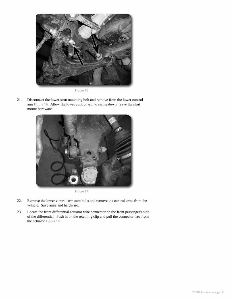
20. Loosen but do not remove the lower control arm cam bolts. On the front, loosen the bolt from the front. On the rear, loosen the nut from the front Figure 16.
T2502 Installation - pg. 11
Figure 16
21. Disconnect the lower strut mounting bolt and remove from the lower control arm Figure 16. Allow the lower control arm to swing down. Save the strut mount hardware.
Figure 17
22. Remove the lower control arm cam bolts and remove the control arms from the vehicle. Save arms and hardware.
23. Locate the front differential actuator wire connector on the front passenger's side of the differential. Push in on the retaining clip and pull the connector free from the actuator Figure 18.
T2502 Installation - pg. 12
Figure 18
24. Locate the differential vacuum and breather lines on the upper driver's side of the differential Figure 19. Disconnect the lines from the hard lines at the frame.
Figure 19
25. Disconnect the front driveshaft from the front differential by removing the four mounting nuts. Save nuts. Pull the driveshaft free from the differential input flange.
26. With the help of an assistant, support the front differential with a proper jack. Remove the outer bolt and inner nut mounting the rear differential bracket to the frame. Remove the bolt mounting the rear differential bracket to the differential and remove the bracket from the vehicle Figure 20A. Save bracket and hardware. Remove the two bolts mounting the front differential brackets to the frame Figure 20B and remove the differential from the vehicle.
T2502 Installation - pg. 13
Figure 20A
Figure 20B
27. In order to clear the differential in its new lower position the factory rear frame crossmember must be removed. On the driver's side make cut marks up the front and back faces of the crossmember that extend from the bottom inside edge of the control arm pocket Figure 21A. This line will be approximately 3-13/16" from the front outer control arm pocket edge Figure 21B and 3-3/8" from the inside of the frame on the back face Figure 21C. Connect the top of the two vertical cut lines along the top surface of the crossmember.
T2502 Installation - pg. 14
Figure 21A
Figure 21B
Figure 21C
28. On the passenger's side, measure in and mark 3" from the inside edge of the con-trol arm pocket Figure 22. Extend the line along the bottom of the crossmember (parallel to the inside edge of the control arm pocket) and up the front and back faces of the crossmember.
T2502 Installation - pg. 15
Figure 22
29. Using a reciprocating saw (highly recommended), hack saw or cut-off wheel, cut the rear crossmember out of the vehicle along the driver's and passenger's side cut lines Figure 23.
Figure 23
30. With the rear crossmember removed, clean any burrs, grease/oil and paint from the cut area. Prep the area properly for welding in the new provided metal plates.
31. Position the provided driver's and passenger's side weld-in plates up to the cut surfaces by matching up the profiles Figure 24-pass, Figure 25-drv. On the driv-er's side make sure the bottom edge of the new plate is even with the bottom-most edge of the cut. Tack weld the plates in place.
T2502 Installation - pg. 16
Figure 24-passenger's side
Figure 25-driver's side
32. Double check the weld-in plate positions and completely weld into place. Once the weld area has cooled, paint any bare metal to prevent rust.
33. Locate the (2) provided front crossmember crush sleeves (0.875 OD x 2.250 Long). Place the sleeve in the top differential mounting holes in the crossmem-ber. Take care not to drop them into the crossmember tube. Figure 26
Figure 26
Step 33 NoteFront crossmember hardware is located in hardware pack #650.
T2502 Installation - pg. 17
34. Install the new front crossmember into the front lower control arm pockets Figure 27 with the provided 7/8" x 5-1/2" bolts and (2) provided rectangle cam washers (set with large hole). Run the bolts from front to rear and loosely fasten with remaining (2) rectangle cam washers and 7/8" nylock nuts.
Figure 27
35. Locate and replace the factory vacuum and breather lines on the top of the dif-ferential Figure 28. Transfer the hose clamps from the factory breather hose to the new provided one. The vacuum line does not have clamps and just slides onto the hard line.
Figure 28
36. With the help of an assistant and an appropriate jack, raise the differential up to the new front crossmember. Align the holes in the factory differential mount brackets with the corresponding holes in the crossmember. Fasten the differen-tial Figure 29 to the front crossmember (through the holes with the crush sleeves) with 9/16" x 5-1/2" bolts, nuts and washers along with the large lower factory washer. Leave hardware loose.
Step 36 NoteAll front differential mounting hardware is located in hardware pack #652.
T2502 Installation - pg. 18
Figure 29
37. Locate the factory rear differential mount that was removed earlier. Locate the bottom outer mount surface and the cast ribs that extend close to the mounting hole. These ribs need to be ground down flush to the mounting surface back into the mount body about 1/4" to provided clearance with the new differential mount Figure 30. This can easily be done with a standard angle grinder.
Figure 30
38. Loosely install the modified factory rear differential mount to the differential with the original bolt Figure 31. The mount should be positioned as it was when removed with the captive stud to the inside and pointing down. Leave the bolt loose so the bracket can move freely.
T2502 Installation - pg. 19
Figure 31
39. Install the new rear crossmember in the rear lower control arm pockets Figure 32. When installing the crossmember, align the captive stud on the rear differential bracket with the mounting hole in the crossmember. Fasten the crossmember to the frame with the provided 18mm x 170mm bolts and (2) rectangle cam wash-ers (set with small hole). Run the bolts from rear to front. Install the remaining (2) cam washers on the bolt but do not install the nut.
Figure 32
40. With the rear crossmember installed, fasten the factory rear differential mount to the outer crossmember mount with a 9/16" x 2-1/2" bolt, nut and washers. Also, install the factory flanged high nut on the captive stud, which is accessed through the bottom of the rear crossmember Figure 33. Leave hardware loose.
Step 40 NoteAll front differential mounting hardware is located in hardware pack #652.
T2502 Installation - pg. 20
Figure 33
41. After all of the differential hardware is installed, push the differential rearward as far as possible and torque the two front differential mount bolts to 90 ft-lbs. Leave the remaining differential hardware loose at this time.
42. Connect the new differential breather and vacuum lines to the hard lines at the frame on the driver's side. Reconnect the differential wiring connector to the differential actuator.
43. Reconnect the front driveshaft to the differential with the original nuts/washer. Torque nuts to 50 ft-lbs.
44. Locate and install the factory lower control arms into the new front and rear crossmembers Figure 34. Loosely fasten the control arms with the factory cam bolts. The front cam bolts run from front to rear and the rear cam bolts run from rear to front. Thread the cam bolts just enough to seat the cams between the cam stops on the crossmembers but do not tighten.
Figure 34
45. With the lower control arms installed, go back and torque the (3) rear differential mount bolts to 90 ft-lbs (two at the crossmember, one into the differential).
46. With all the differential mount bolts tight, torque the main 7/8" front crossmem-ber bolts to 250 ft-lbs.
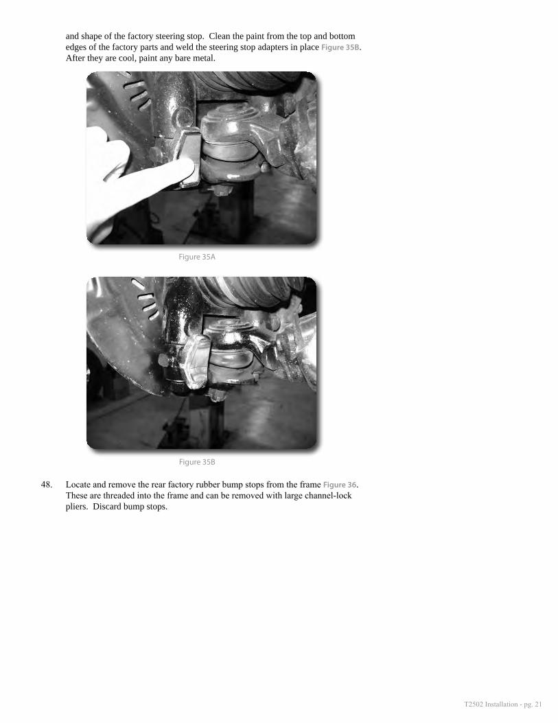
47. Locate the provided weld-on steering stop adapters. Position the adapters on the factory steering stops, located on the ball joint mounts toward the front side of the control arm Figure 35A. The adapters will roughly match the contour
T2502 Installation - pg. 21
and shape of the factory steering stop. Clean the paint from the top and bottom edges of the factory parts and weld the steering stop adapters in place Figure 35B. After they are cool, paint any bare metal.
Figure 35A
Figure 35B
48. Locate and remove the rear factory rubber bump stops from the frame Figure 36. These are threaded into the frame and can be removed with large channel-lock pliers. Discard bump stops.
T2502 Installation - pg. 22
Figure 36
49. Locate the provided driver's and passenger's side bump stop mounts and new bump stops. The new mounts are side specific. The large tab will mount to the rear crossmember bolt and the small slotted hole mounts to the frame. Install the provided bump stops Figure 37A to the new mounts with a 3/8" flanged nut. Tighten nut securely (do not overtighten, causing the bump stop to deform).
Figure 37A
50. Install the bump stop mounts to the original bump stop location on the frame with 10mm x 25mm bolts and 3/8" USS washers. Before installing the bolt make sure the rectangle cam washer is in place on the crossmember bolt Figure 37B - installed earlier and the bump stop mount is positioned over the cam washer. Leave 10mm hardware loose and fasten the mount at the crossmember with a 3/4" washer and 18mm nut. Torque the 10mm bolt to 20 ft-lbs followed by the 18mm bolt to 140 ft-lbs.
Step 49,50 NoteBump stop hardware is located in hardware pack #649.
Step 50 NoteThe 18mm nuts and 3/4" wash-ers for the crossmember bolts are located in hardware pack #650.
T2502 Installation - pg. 23
Figure 37B
Figure 37C
»loWer Strut Mount aSSeMbly
51. Locate the new lower strut extension assemblies. Install the extension on the factory strut so the pinch tabs are toward the inside of the vehicle. Slide the extension over the strut body. Figure 38
Note: 2014 models will require the use of a rubber mallet or dead blow hammer to get the strut mount over the narrow section of the strut body and will not fit bilstein equipped vehicles.
Figure 38
Step 51,52 NoteStrut mount hardware is located in hardware pack #648.
2007-2013 models only: The extension may need to be tapped on to Bilstein struts because of the slightly larger body diameter. Use a rubber mallet.
T2502 Installation - pg. 24
52. Align the mount holes with the factory strut bushing and fasten with a 5/8" x 3" bolt, nut and washers. Torque bolt to 125 ft-lbs.
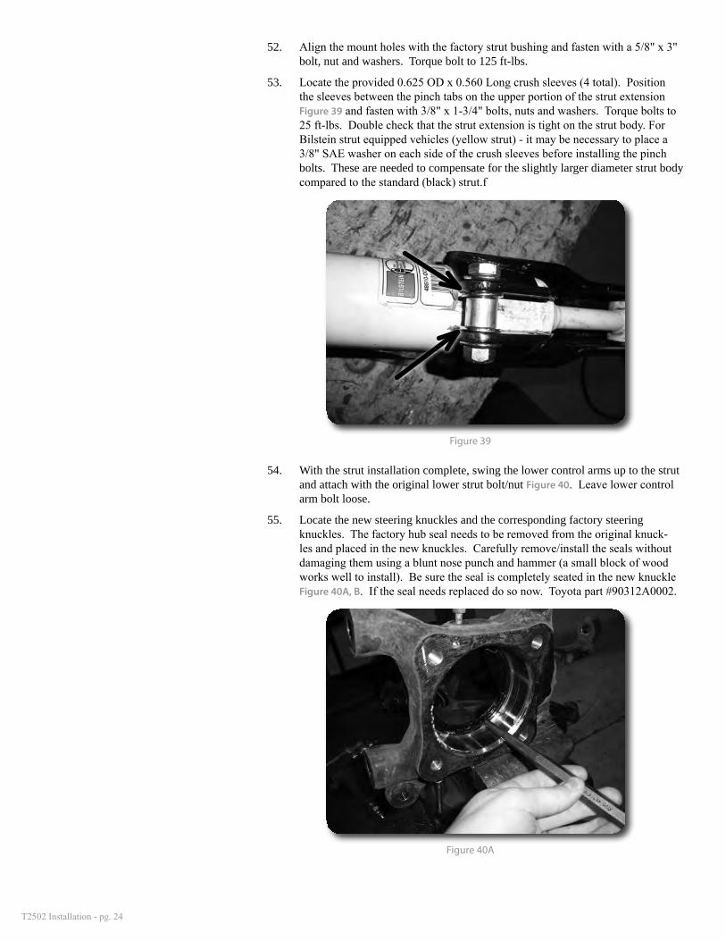
53. Locate the provided 0.625 OD x 0.560 Long crush sleeves (4 total). Position the sleeves between the pinch tabs on the upper portion of the strut extension Figure 39 and fasten with 3/8" x 1-3/4" bolts, nuts and washers. Torque bolts to 25 ft-lbs. Double check that the strut extension is tight on the strut body. For Bilstein strut equipped vehicles (yellow strut) - it may be necessary to place a 3/8" SAE washer on each side of the crush sleeves before installing the pinch bolts. These are needed to compensate for the slightly larger diameter strut body compared to the standard (black) strut.f
Figure 39
54. With the strut installation complete, swing the lower control arms up to the strut and attach with the original lower strut bolt/nut Figure 40. Leave lower control arm bolt loose.
55. Locate the new steering knuckles and the corresponding factory steering knuckles. The factory hub seal needs to be removed from the original knuck-les and placed in the new knuckles. Carefully remove/install the seals without damaging them using a blunt nose punch and hammer (a small block of wood works well to install). Be sure the seal is completely seated in the new knuckle Figure 40A, B. If the seal needs replaced do so now. Toyota part #90312A0002.
Figure 40A
T2502 Installation - pg. 25
Figure 40B
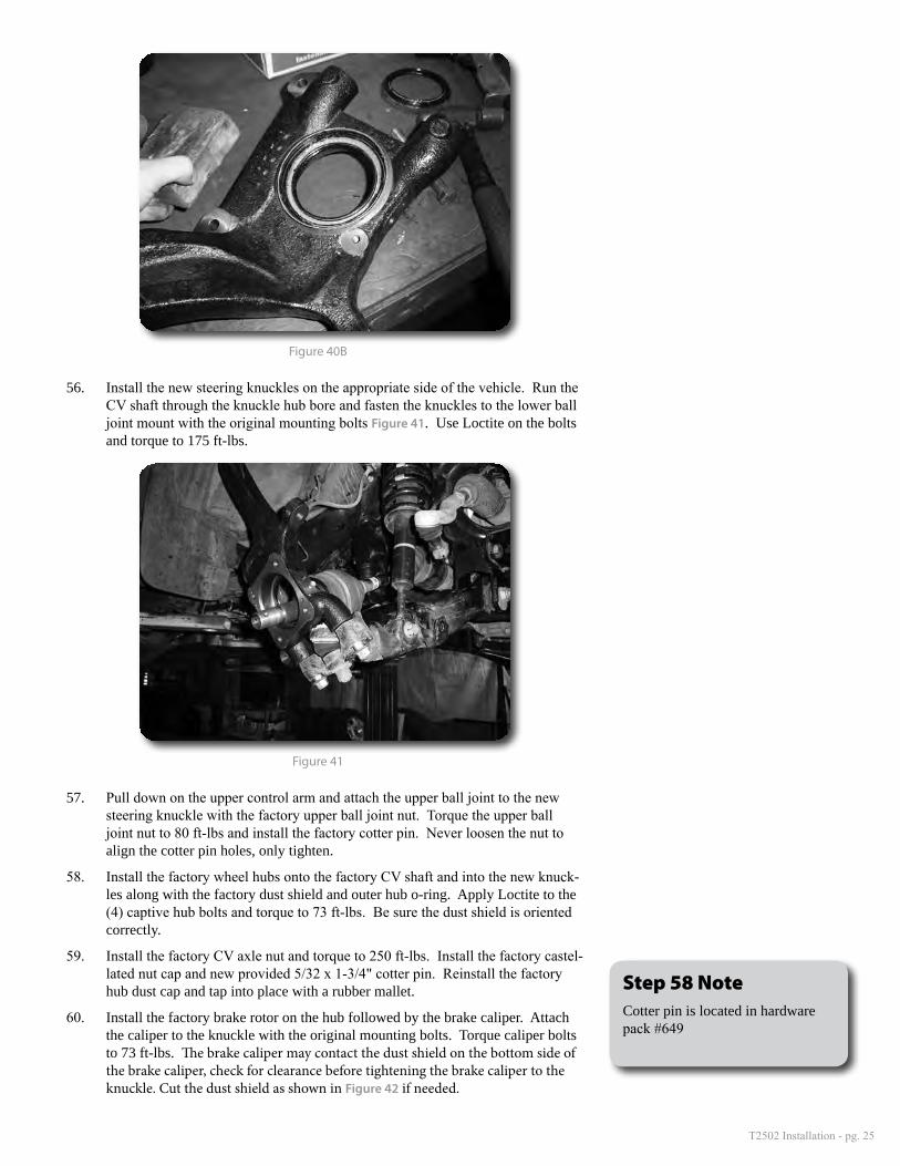
56. Install the new steering knuckles on the appropriate side of the vehicle. Run the CV shaft through the knuckle hub bore and fasten the knuckles to the lower ball joint mount with the original mounting bolts Figure 41. Use Loctite on the bolts and torque to 175 ft-lbs.
Figure 41
57. Pull down on the upper control arm and attach the upper ball joint to the new steering knuckle with the factory upper ball joint nut. Torque the upper ball joint nut to 80 ft-lbs and install the factory cotter pin. Never loosen the nut to align the cotter pin holes, only tighten.
58. Install the factory wheel hubs onto the factory CV shaft and into the new knuck-les along with the factory dust shield and outer hub o-ring. Apply Loctite to the (4) captive hub bolts and torque to 73 ft-lbs. Be sure the dust shield is oriented correctly.
59. Install the factory CV axle nut and torque to 250 ft-lbs. Install the factory castel-lated nut cap and new provided 5/32 x 1-3/4" cotter pin. Reinstall the factory hub dust cap and tap into place with a rubber mallet.
60. Install the factory brake rotor on the hub followed by the brake caliper. Attach the caliper to the knuckle with the original mounting bolts. Torque caliper bolts to 73 ft-lbs. The brake caliper may contact the dust shield on the bottom side of the brake caliper, check for clearance before tightening the brake caliper to the knuckle. Cut the dust shield as shown in Figure 42 if needed.
Step 58 NoteCotter pin is located in hardware pack #649
T2502 Installation - pg. 26
Figure 42
61. Attach the factory brake line bracket to the new steering knuckle with the original bolt. It might be necessary to carefully reform the brake hard line at the caliper in order to attach the bracket. Torque bolt to 8 ft-lbs.
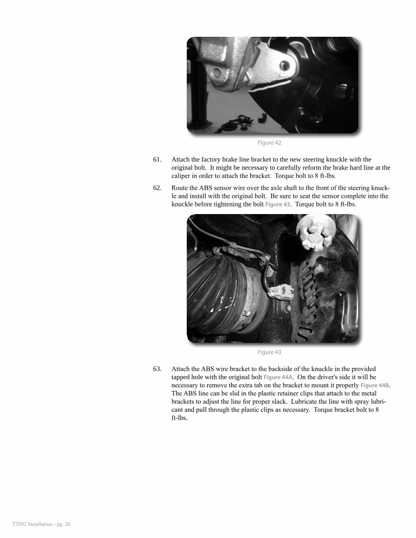
62. Route the ABS sensor wire over the axle shaft to the front of the steering knuck-le and install with the original bolt. Be sure to seat the sensor complete into the knuckle before tightening the bolt Figure 43. Torque bolt to 8 ft-lbs.
Figure 43
63. Attach the ABS wire bracket to the backside of the knuckle in the provided tapped hole with the original bolt Figure 44A. On the driver's side it will be necessary to remove the extra tab on the bracket to mount it properly Figure 44B. The ABS line can be slid in the plastic retainer clips that attach to the metal brackets to adjust the line for proper slack. Lubricate the line with spray lubri-cant and pull through the plastic clips as necessary. Torque bracket bolt to 8 ft-lbs.
T2502 Installation - pg. 27
Figure 44A
Figure 44B
64. Locate the new brake line relocation brackets. Attach the brackets to the origi-nal frame mount with the original bolt. The stud on the bracket will point out and the bracket will angle in toward the strut about 20-30 degrees from vertical Figure 45. Torque bolt to 10 ft-lbs.
Figure 45 - passenger's side view
T2502 Installation - pg. 28
65. Carefully reform the brake hard line at the frame and attach the original brake line mount bracket to the stud on the relocation bracket Figure 46A. Fasten with the provided 1/4" nut, flat washer and lock washer. Tighten hardware securely.
66. Attach the ABS line to the upper control arm with the provided wire clamp Figure 46B.
Figure 46A
Figure 46B
67. Cycle the knuckle back and forth to check for proper slack and clearance of the ABS and brake lines. Adjust where necessary.
68. Locate the new sway bar drop brackets and mount to the original sway bar mount point on the frame rails with the factory hardware. Figure 47 The open face of the brackets should be toward the inside of the vehicle. Torque bolt to 40 ft-lbs.
Step 64 NoteBrake line bracket hardware is located in hardware pack #649
T2502 Installation - pg. 29
Figure 47
69. Loosely fasten the sway bar to the new drop brackets with the provided 7/16" x 1-1/4" bolts, nuts and washers. Be sure the sway bar is oriented correctly and the factory plastic bushing spacers are in place. Figure 48
70. Attach the factory sway bar links to the lower control arms and fasten with the original bolts. Torque link bolts to 90 ft-lbs. Go back and torque the 7/16" sway bar mount bolts to 40 ft-lbs.
Figure 48
71. Remove the factory driver's and passenger's side tie rod ends. Thread the new provided tie rod ends back on up to the jam nut. Figure 49 Install the rod ends into the new steering knuckles (top down) and fasten with the factory castel-lated nut. Torque nut to 51 ft-lbs. Insert a new 5/32 x 1-1/4" cotter pin. Do not loosen the nut to align the cotter pin hole, only tighten.
Step 67 NoteSway bar drop bracket hardware is located in hardware pack #407
T2502 Installation - pg. 30
Figure 49
72. With the new tie rod ends installed, snug the jam nuts up against the tie rod ends.
73. Install the wheels and lower the vehicle to the ground. Torque lug nuts to 100 ft-lbs for aluminum wheels or 150 ft-lbs for steel wheels.
74. Bounce the front of the vehicle to settle the suspension. Torque the lower con-trol arm cam bolts to 200 ft-lbs. Torque the lower strut mount bolts to 140 ft-lbs.
75. Check all hardware for proper torque.
»oPtional front Skid Plate Modification
76. The front skid plate can be cut and mounted in front of the lowered sway bar for aesthetics as well as to provide a mount for the lower bumper plastic tabs.
77. Using a square and tape measure, measure 6-1/4" from the center of the factory front mounting holes and make a cut line across the entire skid plate. Using a plasma cutter (recommended) or reciprocating saw, cut on the line. Figure 50
Step 77 Cut in line with these edges
Step 76 Cut Line
6-1/4"
Figure 50
78. Next cut down both sides of the skid plate along the factory notch. Figure 50 Clean up the edges and paint.
79. Install the skid plate to the frame using the (2) factory bolts. Install the plastic tabs to the skid plate with the (3) factory bolts. Figure 51
T2502 Installation - pg. 31
Figure 51
80. The skid plate can be slightly formed down to be level with the sway bar by gently pulling on the end. Make sure there is enough clearance to the sway bar so interference cannot occur. Modify your cut if necessary.
»rear inStallation
1. Block the front wheels for safety. Raise the rear of the vehicle and support with jack stands under the frame rails.
2. Remove the wheels.
3. Support the rear axle with a floor jack and remove the factory rear shocks. Save the axle mount hardware, discard the upper hardware and shocks
4. Disconnect the parking brake cable brackets from the driver's and passenger's side of the axle Figure 52. Remove the brackets from the cables.
Figure 52
5. Disconnect the rear brake lines from the (3) mounting points at the center of the axle Figure 53A. Save hardware and leave the factory clamps on the hard lines. Disconnect the plastic ABS line clip from the top of the differential Figure 53B. Remove the plastic clip from the ABS line, it will not be reused.
T2502 Installation - pg. 32
Figure 53A
Figure 53B
6. Disconnect the ABS line bracket from the driver's side of the axle Figure 54. Save hardware. Carefully bend the factory ABS line bracket down at the char-coal canister located on the frame Figure 55A,B.
Figure 54
T2502 Installation - pg. 33
Figure 55A—Before
Figure 55B—After
7. With the axle still well supported, remove the passenger's side u-bolts. Lower the axle enough to place the provided lift block between the axle and leaf pack. Align the pins and pin holes in the block, leaf and axle. Raise the axle to seat all of the components. The block has a slight taper. Make sure the short end of the block is toward the front of the vehicle.
8. With the lift block installed, install the new u-bolts, nuts and washers Figure 56. Snug u-bolts but do not torque at this time. Final torque will be done with the weight of the vehicle on the suspension.
T2502 Installation - pg. 34
Figure 56
9. Repeat block installation on the driver's side.
10. With both sides complete, install the new shocks with the provided bushings, sleeves and hardware. New upper hardware is supplied and the factory axle hardware will be reused. Torque the upper shock stud nut to 20 ft-lbs. Torque axle mount bolt to 65 ft-lbs.
11. Locate the provided ABS relocation bracket (flat bracket - 3" hole-to-hole) and attach to the original axle mount with the factory bolt. Position the bracket vertical and torque bolt to 10 ft-lbs. Attach the factory ABS line bracket to the relocation bracket Figure 57 with the provided 5/16" x 1" bolt, nut and washers. Torque 5/16" hardware to 10 ft-lbs.
Figure 57
12. Locate the provided brake line relocation bracket (flat bracket - 1" hole-to-hole), provided 1/4" hardware and wire clip. Install the wire clip on the ABS wire where the factory plastic clip was removed Figure 58A, B. Remove the 1/4" x 1" bolt w/washer through the clip, into the new relocation bracket and into the front of the original ABS mount tab on the top of the differential. Fasten with a 1/4" nut and washer. Position the relocation bracket vertical and torque bolt to 8-10 ft-lbs.
Step 11-13 NoteAll rear brake line hardware is located in hardware pack #651
T2502 Installation - pg. 35
Figure 58A
Figure 58B
13. Attach the factory brake line bracket to the front of the relocation bracket with the remaining 5/16" hardware. Torque bolt to 10 ft-lbs.
14. Flip the two remaining brake hardware line clips and reattach to the original locations on the back of the axle Figure 59. The lines will now be running above the mount bolts instead of below. Torque bolts to 10 ft-lbs.
Step 13 NoteThe brake hard lines will need to be reformed slightly.
T2502 Installation - pg. 36
Figure 59
15. Install the wheels and lower the vehicle to the ground. Torque lug nuts to 100 ft-lbs for aluminum wheels or 150 ft-lbs for steel wheels.
16. Bounce the rear of the vehicle to settle the suspension. Torque the u-bolts to 100-120 ft-lbs.
17. Check all hardware for proper torque.
»PoSt-inStallation
1. Check all hardware (front and rear) for proper torque. Check hardware after 500 miles.
2. Reconnect the battery.
3. Vehicle will need a complete front end alignment.
4. Adjust headlights.
Post-Installation Warnings1. Check all fasteners for proper torque. Check to ensure for adequate clearance between all rotating, mobile, fixed, and heated members. Verify clearance between exhaust and brake lines, fuel lines, fuel tank, floor boards and wiring harness. Check steering gear for clearance. Test and inspect brake system.
2. Perform steering sweep to ensure front brake hoses have adequate slack and do not contact any rotating, mobile or heated members. Inspect rear brake hoses at full extension for adequate slack. Failure to perform hose check/ re-placement may result in component failure.
3. Perform head light check and adjustment.
4. Re-torque all fasteners after 500 miles. Always inspect fasteners and components during routine servic-ing.