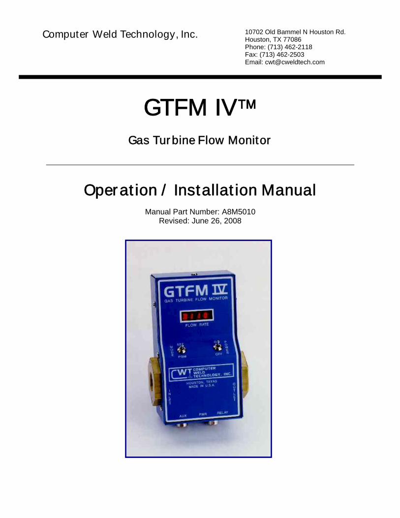
The GTFM IV™ Gas Turbine Flow Monitor, is designed to permit the user to precisely measure the flow rates of the weld shielding gases. WARNING – DO NOT USE WITH ANY FLAMMABLE GASES. The unit comes in both "portable" and "in-line" models and is available in English or Metric versions. The portable version can be used to check the gas flow rates directly at the welding torch. The unit is battery powered, which allows it to be carried throughout the shop. This version is ideal for use by maintenance personnel to correctly set and verify shielding gas flow rates at the welding torch.
1.2 Benefits
The "in-line" version is designed to be permanently installed in a welding fixture to continuously monitor the gas flow rate. When used in this manner the GTFM can provide "sure-flow" gas testing by setting upper and lower control limits for the user defined gas flow rates. An internal fault relay can be used to warn or interrupt the welding process if an out-of-limits condition is detected.
1.3 Features
Some of the features contained in the unit are the capability to limit test, provide an accumulated gas usage and peak flow rates as well as displaying on going gas flow rates. The unit also provides an analog output voltage representing measured gas flow rates.
1.4 Mechanical Specifications
Dimensions 3-1/4"W x 1-3/4"H x 5-3/8”L (85 mm W x 45 mm H x 127 mm L) Weight 23 oz. (652 gm) Pipe Fittings 3/8" NPT with 3/8" hose barb fittings
inductive Analog Sensor Output: 0 - 2.55 vdc @ 10 ma. Analog Scaling 0.01 vdc = 1 CFH (.01 V = 1 LPM) Power Requirement 10 - 28 vdc @ 100 ma. Operating Temperature 20° - 140° F (-7° - 60° C) Battery Charger 120 vac 60 hz @ 300 ma (220 VAC 50 hz @ 300 ma) Battery Life Approximately 2 hours with full charge (English / Metric units of measurement available) Note: Specifications subject to change without notification.
1.6 Models
The following models are covered in this document:
Part No. Description A0A0032 120 VAC Portable GTFM IV™ System A0A0033 240 VAC Portable GTFM IV™ System A0A0064 ADM IV™ GTFM IV™ System A0A0036 120 VAC In-Line GTFM IV™ System A0A0037 240 VAC In-Line GTFM IV™ System
2
2.0 Installation
2.1 Options
The GTFM can be used as a portable or in-line gas flow monitor. If the unit was purchased as a portable monitor, it will be equipped with a rubber gas cone. The cone is designed to fit standard torch gas cups and allows the GTFM to measure the actual gas flow at the torch. To install, simply press the GTFM gas cone onto the welding torch gas cup. Make sure that the cone is fitted snugly to the gas cup.
2.2 Gas Line Hookup
The GTFM may also be installed into the gas line and used to permanently monitor the gas-flow rate. This model is supplied with barbed 3/8 ID hose fittings. The sensor will accept any 3/8” NPT pipefitting. The user may hard plumb the sensor if desired. DO NOT USE PIPE DOPE OR TEFLON TAPE ON THE PIPE FITTINGS. The sensor should be located between the welding-gas solenoid and the torch. DO NOT INSTALL THE SENSOR ON THE INLET SIDE OF THE GAS SOLENOID. If the sensor is installed on the inlet pressure side of the gas solenoid, the maximum operating pressure (50 psi) of the transducer may be exceeded.
WARNING: Do not over tighten fittings as it may twist the sensor out of position.
2.3 Cable Hookup
The GTFM provides an analog voltage, which will represent gas flow. This analog voltage can be monitored by using the Auxiliary Cable and connecting the plug to the "AUX" connector on the bottom panel. The output voltage will have the following relationship:
2.55 volts = 255 cfh or
.01 volts/cfh
The output impedance of this signal is 100 ohms and can source 2 milliamps of current. The analog-interface cable can also be used to supply power to the GTFM. The power requirement is (10 - 28) vdc @ 100 ma.
2.4 Gas Flow Limits
The GTFM can be used to test for High/Low gas flow limits. An internal fault relay will be set (CLOSED) when the gas flow is within the programmed limits. The fault relay can be interfaced to an external weld fixture controller.
3
NOTE: THE FAULT RELAY WILL ONLY BE ACTIVE WHEN POWER IS SUPPLIED VIA THE PLUG-IN TRANSFORMER OR AN EXTERNAL POWER SOURCE CONNECTED TO "AUX" CONNECTOR.
2.5 Gas Flow Volume
The GTFM can also be used to monitor accumulated gas flow and to provide an indication when the volume in a gas cylinder has reached a programmed minimum limit. The GTFM will calculate the volume of gas used based on the measure flow rate. If the user programs the initial volume in a cylinder, and the minimum volume for safe operation, the GTFM will indicate when the estimate minimum volume has been reached. The GTFM will flash a "G" on the display when the estimated cylinder volume has decreased below the programmed minimum. Setting the starting volume “V” to 0 disables the function.
NOTE: THE LOW GAS VOLUME FAULT WILL NOT ACTIVATE THE FAULT RELAY BUT WILL INDICATE THE FAULT CONDITION BY FLASHING A "G" ON THE DISPLAY SCREEN.
4
3.0 Operation
3.1 Firmware Version
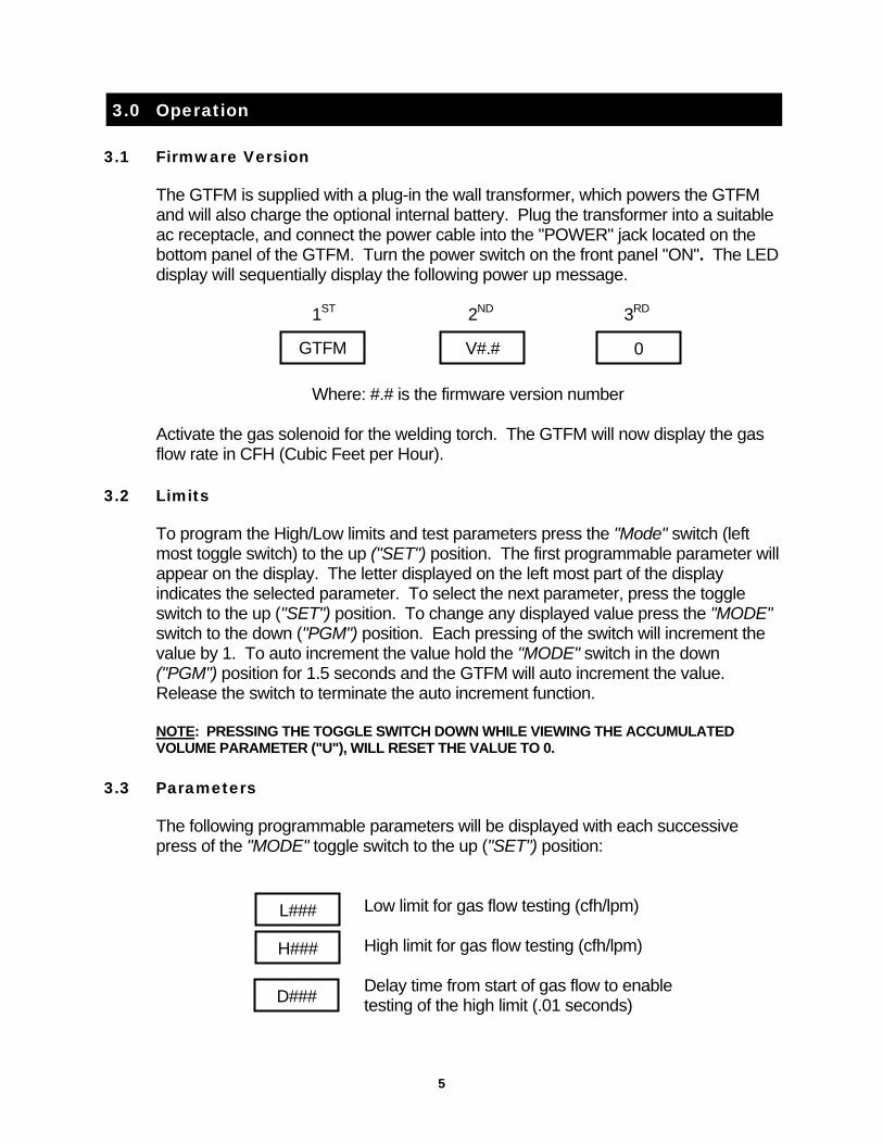
The GTFM is supplied with a plug-in the wall transformer, which powers the GTFM and will also charge the optional internal battery. Plug the transformer into a suitable ac receptacle, and connect the power cable into the "POWER" jack located on the bottom panel of the GTFM. Turn the power switch on the front panel "ON". The LED display will sequentially display the following power up message.
1ST 2ND 3RD
GTFM V#.# 0
Where: #.# is the firmware version number
Activate the gas solenoid for the welding torch. The GTFM will now display the gas flow rate in CFH (Cubic Feet per Hour).
3.2 Limits
To program the High/Low limits and test parameters press the "Mode" switch (left most toggle switch) to the up ("SET") position. The first programmable parameter will appear on the display. The letter displayed on the left most part of the display indicates the selected parameter. To select the next parameter, press the toggle switch to the up ("SET") position. To change any displayed value press the "MODE" switch to the down ("PGM") position. Each pressing of the switch will increment the value by 1. To auto increment the value hold the "MODE" switch in the down ("PGM") position for 1.5 seconds and the GTFM will auto increment the value. Release the switch to terminate the auto increment function. NOTE: PRESSING THE TOGGLE SWITCH DOWN WHILE VIEWING THE ACCUMULATED VOLUME PARAMETER ("U"), WILL RESET THE VALUE TO 0.
3.3 Parameters
The following programmable parameters will be displayed with each successive press of the "MODE" toggle switch to the up ("SET") position:
Low limit for gas flow testing (cfh/lpm) High limit for gas flow testing (cfh/lpm) H###
L###
Delay time from start of gas flow to enable
testing of the high limit (.01 seconds) D###
5
Test time that the flow must be continuously T### out of limits before activating the fault relay
(0.01 seconds).
P### The peak gas flow value detected (cfh/lpm)
The peak gas flow value detected (cfh/lpm) M### that when reached, will provide a low gas volume
The total volume of gas used based U### on actual gas flow rates and time.
(0 - 999 cubic ft/liters)
Where: ### is the current value for the selected parameter. After displaying the last parameter, the GTFM will return to the normal display mode. If a "MODE" switch function is not activated within 20 seconds, the GTFM will automatically return to the normal display mode.
3.4 Battery Specifications
The portable GTFM is supplied with an internal, rechargeable battery. The battery will operate the GTFM continuously for approximately 2 hours when fully charged. The supplied plug-in the wall transformer will recharge the battery in approximately 8-10 hours. The GTFM can be operated while charging the battery. When using the GTFM in battery powered mode the display will automatically clear and a "." will be displayed. This is used to conserve the battery when the GTFM is not measuring actual gas flow. The low power mode will be activated after approximately 25 seconds of no gas flow readings. As soon as gas flow is detected the normal display will return.
6
4.0 SETTING GAS FLOW CONTROL LIMITS
4.1 Description
To use the GTFM as a Sure-Flow gas switch, the user can set the upper ("H") and Lower ("L") limits by using the "PGM" toggle switch. The GTFM will activate the internal fault relay as long as the gas flow remains above the lower limit and below the upper limit. If the gas flow rate moves outside of the control limits the fault relay will be deactivated. The "D" parameter is used to delay the start of high limit testing. The value of this parameter will determine when the GTFM will begin testing for the upper control limit after the gas flow is initiated. The lower limit is always being check during the gas flow period. A high gas flow fault will only occur after this time period has expired. The "T" parameter is used to specify the amount of time that the gas flow rate must be continuously above or below the control limits before setting a gas fault condition.
4.2 Setup
To set the lower limit select the "L" parameter by pressing the "MODE" switch to the up ("SET") position until the "L" parameter is displayed. While viewing the "L" parameter press the "MODE" switch to the down ("PGM") position to increment to the desired value. To set the Upper limit select the "H" parameter by consecutively pressing the "MODE" switch to the up ("SET") position until the "H" parameter is displayed. While viewing the "H" parameter press the "MODE" switch to the down ("PGM") position to increment to the desired value.
NOTE: The lower limit will increment up to the value set by the upper ("H") parameter
then it will reset to the 0. The High limit will increment to 255 then reset to the lower ("L") parameter value.
7
5.0 GAS FLOW SURGE "P" MEASUREMENT
5.1 Description
The GTFM has a peak value "sample and hold" feature. This allows the user to measure the maximum gas flow rate, which occurred during the welding cycle. The maximum value is the result of a gas surge, which occurs when the gas solenoid is activated. The "MODE" switch on the front panel is used to display the maximum flow rate. The maximum value is displayed by pressing the "MODE" switch to the up position consecutively until the "P" parameter is displayed. The maximum value is reset during power up and when the GTFM first detects gas flow.
8
6.0 GAS FLOW USAGE "U" MEASUREMENT
6.1 Description
The GTFM has a gas flow accumulator, which can be used to display total gas usage. This function allows the user to measure the total cubic ft. or liters of gas used from the last time that the accumulator was reset. The maximum volume displayed is 999 cubic ft. If the usage exceeds this value the accumulator will be reset to 0 and will count up from zero as the usage increases.
NOTE: WHEN GTFM IS EMPLOYED TO MEASURE METRIC VOLUME, THE DISPLAYED USAGE NUMBER MUST BE MULTIPLIED BY TEN (10) TO OBTAIN ACCURATE READING.
6.2 Setup
The accumulated usage value is displayed by consecutively pressing the "MODE" switch to the up ("SET") position consecutively until the "U" parameter is displayed. The value can be reset to zero by pressing the "MODE" key down to the "PGM" position.
NOTE: THE GTFM PROVIDES A REASONABLE ESTIMATE OF SHIELDING GAS
USAGE. HOWEVER, THIS NUMBER CANNOT BE CONSIDERED TO BE ABSOLUTE SINCE THE GTFM DOES NOT MEASURE OR MONITOR OTHER VARIABLES, WHICH MAY HAVE AN EFFECT ON GAS USAGE, SUCH AS PRESSURE AND TEMPERATURE.
9
7.0 GAS CYLINDER LOW VOLUME MEASUREMENT
7.1 Description
The GTFM can be used to provide the user with an indication of when the volume in a cylinder of gas is reaching a low level. To use this function the user must set the starting volume in the cylinder and a minimum value for testing. When the minimum value is reached the GTFM will flash a "G" on the display. The GTFM will display the flashing "G" until the original volume is zero. To disable this function set the "V" parameter to zero.
7.2 Setup
To set the starting volume select the "V" parameter by consecutively pressing the "MODE" switch to the up ("SET") position until the "V" parameter is displayed. While viewing the "V" parameter press the "MODE" switch to the down ("PGM") position to increment to the desired value. To set the minimum limit select the "M" parameter by pressing the "MODE" switch consecutively to the up ("SET") position until the "M" parameter is displayed. While viewing the "M" parameter press the "MODE" switch to the down ("PGM") position to increment to the desired value.
10
8.0 GTFM CONNECTOR PIN ASSIGNMENT
8.1 AUX Connector
The following is the pin assignment for the "AUX" sensor connector:
Pin No. Function 1 + Power input (10 - 24 vdc @ 100ma) 2 + Analog gas flow rate output 3 - Analog gas flow rate output 4 Common power input 5 Common power input
The following is the pin assignment for the "RELAY" connector:
Pin No. Function 1 Relay common 2 N.C. - Will be open when gas flow is within programmed limits. 3 N.O. - Will be closed when gas flow is within programmed limits.
To open the unit, remove the eight (8) screws on the sides of the box. Do not remove the two socket screws in the brass fittings on each side of the box where the inlet/outlet holes are. Carefully lift the cover off. Unplug the battery from JP4. Install the new battery pack and plug the battery onto JP4. Make sure that the Red wire is toward the "RED" marking on the P.C. board and the Black Wire is toward the "BLK" marking on the P.C. board. Reinstall the cover and the eight (8) mounting screws. CWT Replacement Part - P/N X3B5008 4.8V Rechargeable Battery.
12
10.0 MODEL SPECIFICATIONS
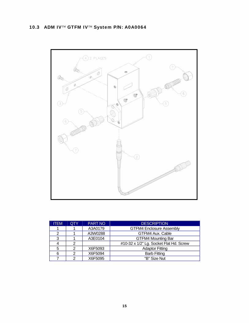
10.1 120 VAC Portable GTFM IV™ System P/N: A0A0032