PART 1 – GENERAL ............................................................................................................................. 1�1.01� SUMMARY ........................................................................................................................... 1�
2.03� FINISHES ............................................................................................................................ 22�2.04� SOURCE QUALITY CONTROL ......................................................................................... 22�
PART 3 – EXECUTION ....................................................................................................................... 23�
3.01� FIELD QUALITY CONTROL ............................................................................................. 23�3.02� DEMONSTRATION ............................................................................................................ 23�
1. Requirements for design, manufacturing, furnishing, integration, shop assembly,
inspection, factory testing, installation supervision, pre-commissioning test, commissioning tests, support up to the date of the ACP’s issuance of Taking-Over
Certificate, testing after completion, training services and maintenance of thirty-eight
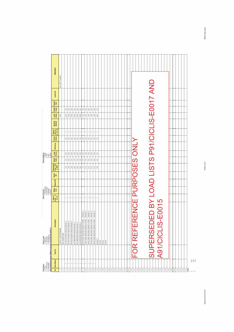
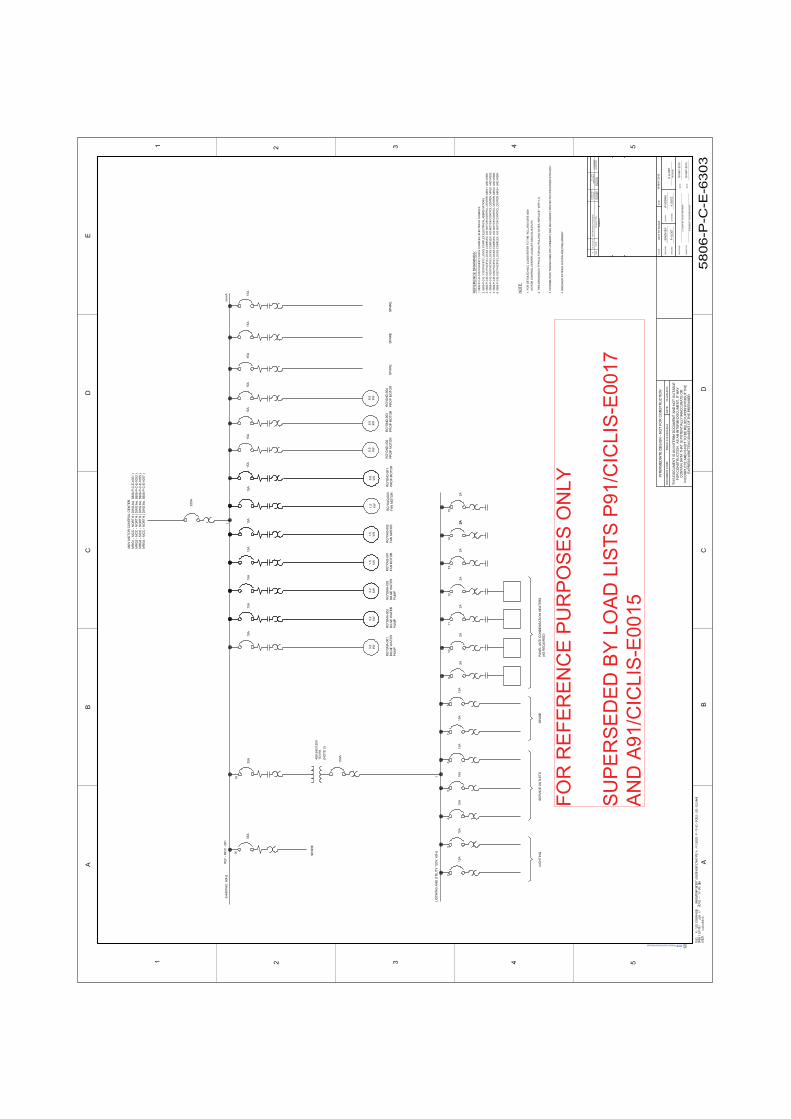
(38) 600V Motor Control Centers (MCC’s) for each of the two (2) locks, arranged as shown on the Drawings and with the load requirements as shown on the 480V
electrical load lists, complete with the required non-segregated phase bus duct
(NSPBD) tie sections and all accessories as hereinafter specified. The above MCC’s include eight (8) outdoor rated MCC’s for the rolling gate loads. The scope of supply
shall also include twelve (12) outdoor rated, NEMA 4X heavy duty disconnect
switches for the locks dewatering pumps at each of the locks, as listed in the
electrical load lists. The work shall include all necessary equipment and appurtenances for the safe, efficient, and reliable operation of the equipment within
the scope of this specification whether or not such items are specifically referred to in
the specification. Thirty MCC’s will be located indoor at the Machinery Rooms for Gates (MR-G’s), Machinery Rooms for Culvert Valves (MR-V’s), and Machinery
Rooms for Conduit Valves (MR-WSB’s) and Locks Dewatering Electrical Rooms
(LDER’s); and eight MCC’s (Rolling Gates Loads) will be located outdoors.
B. Products Supplied But Not Installed Under This Section
Table 1 - MCC Buses
MCC Bus Location (at both Locks)
MRG1-MCC-NORTH MR-G1 North
MRG1-MCC-SOUTH MR-G1 South
MRG2-MCC-NORTH MR-G2 North
MRG2-MCC-SOUTH MR-G2 South
MRG3-MCC-NORTH MR-G3 North
MRG3-MCC-SOUTH MR-G3 South
MRG4-MCC-NORTH MR-G4 North
MRG4-MCC-SOUTH MR-G4 South
MRWSB1-MCC-NORTH MR-WSB1 North
MRWSB1-MCC-SOUTH MR-WSB1 South
MRWSB2-MCC-NORTH MR-WSB2 North
MRWSB2-MCC-SOUTH MR-WSB2 South
Contract No. CMC-221428, Design and Construction of the Third Set of Locks
4. G91/CICTSP-E0008 (Section 26 29 23) Variable Frequency Drive
1.02 REFERENCES
A. The design, fabrication, and testing of all work shall be in accordance with all applicable
laws and regulations of the Republic of Panama, Autoridad del Canal de Panama and
industry standards. References to these documents are to the latest issue date of each
document, unless otherwise indicated, together with the latest additions, addenda, amendments, supplements, etc., thereto, in effect as of the date of contract for the work.
Abbreviations listed indicate the form used to identify the reference documents in the
Specification text. The specified equipment shall be designed and constructed in accordance with the Standards listed reference in this Section or the referenced sections
of the Employer’s Requirements.
B. American Society for Testing and Materials (ASTM) International Standards
1. ASTM D 3951 Standard Practice for Commercial Packaging
C. American National Standard Institute (ANSI) Standards
1. ANSI C2 The National Electrical Safety Code
2. ANSI C37.51 Metal-Enclosed Low-Voltage AC Power Circuit Breaker Switchgear Assemblies – Conformance Test Procedures
3. ANSI C37.52 Test Procedures for Low Voltage AC Power Circuit
Protectors Used in Enclosures
4. ANSI C84.1 Standard for Electric Power Systems and Equipment –
Voltage Ratings (60 Hertz)
D. Autoridad del Canal de Panamá (ACP) Employer’s Requirements:
1. Section 01 10 00 General Project Requirements
2. Section 01 33 00 Submittal Procedures
3. Section 01 40 00 Quality Requirements
4. Section 01 77 00 Taking-Over Procedures
5. Section 01 78 23 Operations Data
6. Section 01 79 00 Demonstration and Training
7. Section 01 86 13 Plant Mechanical Systems and Equipment
8. Section 01 91 00 Tests on Completion and Tests After Completion
9. Section 01 92 00 Facility Operation
10. Section 01 93 00 Maintenance Services
11. Section 09 90 00 Painting
12. Section 26 05 53 Identification for Electrical Systems
13. Section 26 20 00 Electrical Low Voltage Distribution Work
14. Section 26 43 13 Transient Voltage Surge Suppresors (TVSSs)
15. Section 26 90 00 Field Testing Electrical Systems
Contract No. CMC-221428, Design and Construction of the Third Set of Locks
a. Equipment shall be designed for indoor (MCC's and tie connections) and outdoor
(heavy duty safety disconnect switches and MCCs) installation in a high humidity coastal environment with a minimum life expectancy of 40 years under
the project conditions specified in Section 1.08.
b. Equipment and components shall be designed and constructed to resist the effects
of earthquake motions in accordance with IBC 2006 and ASCE 7-05. The following criteria shall be used to certify seismic compliance:
1) Atlantic Side:
a) Component Importance Factor, Ip = 1.5
b) Design Spectral Response Acceleration at Short Periods:
(1) SDS = 0.85g
2) Pacific Side:
a) Component Importance Factor, Ip = 1.5
b) Design Spectral Response Acceleration at Short Periods:
(1) SDS = 1.60g
2. Utility Data
Frequency 60 Hz
Voltages Available 12000V, 3-phase
480V, 3-phase 208V, 3-phase
120V, 1-phase
125 VDC 3. Motor Control Centers (MCC’s), FVNR combination local starters and disconnect
switches shall be 600 Volts class suitable for operation on a 480/277V, 60 Hz, three-
phase, four-wire, grounded-wye system. Control circuit components for main and tie
circuit breakers shall be rated for 125 VDC operation.
4. Harmonic generation equipment in the MCC’s shall comply with the latest edition of
IEEE 519 for total harmonic voltage and current distortion calculation and
measurement and meet the following distortion limits:
a. Voltage Harmonics: Not more than 3% total harmonic voltage distortion while
operating from the utility source, or not more than 5% while operating from
standby generator.
b. Current Harmonics: Maximum allowable total harmonic current distortion limits shall not exceed 5%.
5. Circuit breakers, combination starters, and auxiliary equipment of the same type and
rating shall be physically and functionally interchangeable. Like parts, when interchanged, shall perform their function equally well in every respect.
6. The indoor MCC’s shall have the following ratings:
a. Quantity of MCC's 30 per Complex
b. Voltage Class 600 Volts
Contract No. CMC-221428, Design and Construction of the Third Set of Locks
According to Article 7.2 of IEEE Std C37.23 - Separate ground bar shall
be provided.
9. Arc-Flash Protection
a. Motor control centers shall have Arc-Flash protection construction, and shall
include the supply of one (1) remote racking device per site.
10. The outdoor rated heavy duty safety disconnect switches and all components shall be designed, manufactured and tested in accordance with NEMA KS-1 and UL 98. The
safety switches shall have the following ratings:
a. Quantity 12 per Complex
b. Voltage Class 600 Volts
c. Nominal Voltage 480/277V, 60 Hz
d. Service 3-Phase, 4-Wire
e. Enclosure Type NEMA 4X, Stainless Steel
f. Fusible/Non-fusible Non-fusible
g. Continuous Current 800A
h. Minimum Fault Withstand 65kA
11. The Supplier shall meet all applicable requirements of Section 40 00 00 (Process
System Integration) of the Employer’s Requirements.
B. Performance Requirements
1. Equipment performance shall be in accordance with applicable industry standards.
2. The equipment supervision and control performance shall be in accordance with the
requirements of Section 40 00 00 (Process System Integration) of the Employer’s
Requirements.
1.05 SUBMITTALS
A. General
1. The Supplier shall comply with the Submittal requirements specified in the Employer’s
1. The Supplier shall identify and code all the supplied equipment, component and parts in
accordance with the requirements of Document G00/CICTCR-G0001 (Nomenclature and Identification Plan). All information shall be provided in electronic data base format to be
approved by the Contractor.
D. Integration
Contract No. CMC-221428, Design and Construction of the Third Set of Locks
1. The Contractor is providing a fully integrated and functional Canal transportation system
that requires full integration of electrical and mechanical support systems to meet the operation objectives of the Employer. The Supplier shall provide all the necessary
technical information, shall participate in the Integration Team and provide all the
coordination necessary to ensure that the equipment and components specified in this
Section are fully integrated.
2. The Supplier shall provide all the information; and participate in the integration team as
required in Document G80/CICDSR-E0001 (Integration Management Plan).
E. CADD Drawings
1. The Supplier shall provide three-dimensional CADD outline drawings of major
equipment items supplied, in Autodesk Revit 2010-compatible format. Supplier shall also
provide the required equipment modeling information compatible with Autodesk Revit.
2. Drawing content and format shall be in conformance with Contractor's CADD Manual,
document G00/CICCAD-G0001 (CADD Manual).
F. All electrical drawings shall be prepare and submitted in AutoCad Electrical 2010 format.
Other type of drawings shall be submitted in AutoCad 2010 format.
G. Product Data
1. The Supplier shall submit copies (hard and electronic) of the drawings and complete
technical literature (including datasheets and time-current characteristic curves for protective devices) describing the equipment to be furnished.
2. UL certification for motor control and safety switches fabrication
H. Shop Drawings
1. Detailed dimensional drawings, including equipment weight and accessories
2. Structural loading drawings and certification of compliance with seismic design
requirements for each of the sites
3. Connection diagrams and schematic diagram drawings
4. One line and three lines drawings
5. Nameplate drawing/information
I. Quality Assurance/Control Submittals
1. For submittal procedures and general requirements refer to ACP ER Section 01 33 00
(Submittal Procedures)
2. Manufacturer's Instructions
a. Installation and Field Test Procedures, including the pass/fail criteria for field tests
3. Manufacturer's Test Reports
a. Certified Factory Test Reports
J. Closeout
1. Maintenance documentation in accordance with G00/CICTSP-G0002 (Maintenance
Documentation Package)
Contract No. CMC-221428, Design and Construction of the Third Set of Locks
1. For Quality Assurance general requirements refer to document G00/UPCQMM0001
(Quality Management Manual) and ACP ER Section 01 40 00 (Quality
Requirements).
2. In the event of a conflict between the referenced standards, Project Designer drawings, and this Specification, the Supplier shall notify the Project Designer and
secure a written clarification as to what is acceptable before proceeding with the
work.
B. Qualifications
1. Manufacturer shall be a firm specialized in manufacturing motor control centers with
minimum of ten years experience.
1.07 DELIVERY STORAGE AND HANDLING
A. Packaging and Marking
1. All equipment, spare parts, tools, and inventory, shall be protected to withstand rough
handling and corrosive environments during ocean shipment. Packing shall be in accordance with ASTM D 3951.
a. Corrosion Prevention: All finished parts and surfaces that are subject to corrosion
shall be coated and protected with a corrosion-resistant compound.
b. Materials and Equipment Cleaning: The equipment, spare parts, tools, inventory,
and materials shall be clean and free of all foreign material.
c. Repainting: The surfaces of each equipment where paint has been damaged during shipment shall be cleaned and touched-up with a surface preparation and
paint matching the approved coating system.
2. Delivery
a. The Contractor shall deliver the equipment and components in accordance with these specifications. Items that, in the opinion of the Employer’s Representative,
are damaged or defective shall be replaced by the Contractor at its own cost.
Unless otherwise indicated, each lock gate shall be delivered to its designated destination, in accordance with the Contract’s delivery schedule.
1.08 PROJECT CONDITIONS
A. Existing Conditions
1. Site Data
Elevation 0 – 610 m above sea level
Ambient Temperature 10°C (50°F) – 40°C (104 °F) with an average of 30°C (86°F)
Relative Humidity From 60 to 95%, non-condensing, with an average of 88%
Vibration 5 Hz to 30 Hz with peak random vibrations of 2g
Wind Speed 130 km/hr (80 miles/hr) steady, in any direction, gust
factor of 1.3
Contract No. CMC-221428, Design and Construction of the Third Set of Locks
A. The Supplier shall comply with the Contractor’s schedule to the design of the project
Intermediate, Final and Issued-For-Construction activities and coordination with other
Suppliers.
B. The schedule shall be as stated in the Request for Proposal.
1.10 WARRANTY
A. The warranty shall be as stated in the Request for Proposal.
1.11 SYSTEM START UP, EMPLOYERS INSTRUCTIONS AND COMMISSIONING
A. Support during start-up, Employer’s Instructions and Commissioning shall be as
specified in Part 3.
1.12 MAINTENANCE
A. The Supplier shall provide as an option a 3-Year maintenance Service starting after the
issuance of the Taking Over Certificate (TOC) by Employer in full compliance with
Section 01 93 00 (Maintenance Services).
1. The work shall also include start-up spare parts and special tools required for erection.
2. Supplier shall furnish a list of recommended spare parts for 3 years of operation. The
list shall indicate which parts the Supplier recommends be carried in stock. The catalog number, lead-time and price shall be included
1.13 MAINTENANCE
A. The Supplier shall provide as an option a 3-Year maintenance Service starting after the issuance of the Taking Over Certificate (TOC) by Employer in full compliance with
Section 01 93 00 (Maintenance Services).
B. The work shall include start-up spare parts and special tools required for erection.
C. Supplier shall furnish a list of recommended spare parts for 3 years of operation. The list shall indicate which parts the Supplier recommends to be carried in stock. The catalog
number, lead-time and price shall be included.
PART 2 – PRODUCTS
2.01 MANUFACTURED UNITS
A. MCC structures shall be totally enclosed, with arc flash protection construction, NEMA
Type 1 Gasketed, dead-front and free-standing assemblies. Structures shall contain a
horizontal wireway at the top, isolated from the horizontal bus and shall be readily accessible through a hinged cover. Adequate space for conduit and wiring to enter the top
or bottom shall be provided without structural interference. Local heavy duty safety
disconnect switches shall have NEMA 4X enclosures with padlocking facilities.
B. Compartments for mounting tap feeders shall be incrementally arranged such that not
more than twelve units can be mounted within each vertical section.
Contract No. CMC-221428, Design and Construction of the Third Set of Locks
C. Each operating unit shall contain all the required equipment, mounted in an individual
cell. All units shall be draw-out type removed from the front, without rear access or disturbing other units in the control center assembly (starters and tap feeders units). All
draw-out type unit assemblies shall have positive guide rail system to ensure alignment of
connection to vertical bus. Units shall be mechanically interlocked with the door to
prevent removal while in the energized position. All ventilating openings shall be provided with corrosion resistant insect-proof screens on the inside. Draw-out units shall
have a silver-plated stab assembly for connection to the vertical bus. No wiring to these
stabs shall extend outside of the draw-out unit. All draw-out units shall be secured by a spring-loaded fastening device.
D. Each compartment shall have a hinged door with concealed or piano type hinges. No
more than six NEMA Size 2 Starters shall be mounted within each vertical section.
E. Units shall be equipped with side-mounted, positive latch pull-apart type control terminal
blocks rated 600 volts. Knockouts/provisions for the addition of future terminal blocks
shall be provided. Load terminals shall also be provided.
F. All the motors control units shall be made with a rigid steel shell, gage as required by NEMA ICS 6. The material shall receive rust inhibiting phosphatizing treatment and have
an enamel finish per ANSI standards. The rear section of the shell shall have a silver-
plated copper alloy stab assembly mounted in a glass-reinforced plastic insulation block that totally shrouds each stab and ensures positive alignment of the stabs with the vertical
bus. The stab assembly shall ensure a positive connection yet permit easy unit insertion
and withdrawal. The power wiring shall be firmly connected to the stabs and totally contained within the unit enclosure.
G. Wiring and terminations shall be Class II Type B as indicated on NEMA ICS 18.
Terminal blocks for control wiring shall be molded or fabricated type with barriers rated
not less than 600 volts. The terminals shall be washer head screw type, or of the stud type with contact and locking nuts. The terminals shall be not less than No. 10 in size and
shall have sufficient length and space for connecting at least two indented terminals for
10 AWG conductors to each terminal. Each block or group of blocks shall have not less than 10 percent spare terminals. Minimum current carrying capacity shall be 20 Amps.
Short-Circuiting Type terminal blocks shall be furnished for all current transformer
secondary leads and shall have provision for shorting together all leads from each current
transformer without first opening any circuit.
H. Each terminal block shall be marked. Terminal blocks marking shall include
corresponding wire designations.
I. Load terminal blocks shall be copper rated not less than 600 volts and of adequate capacity shall be provided. The terminals shall have length and space for at least two
indented terminals of the size required on the conductors to be terminated. For conductors
rated more than 50 amperes, screws shall have hexagonal heads. Conducting parts between connected terminals shall have adequate contact surface and cross section to
operate without overheating and rated 75°C at least. Each connected terminal shall have
the circuit designation or wire number placed on or near the terminal in permanent
contrasting color. Aluminum terminal blocks are not acceptable.
Contract No. CMC-221428, Design and Construction of the Third Set of Locks
J. All control wire shall be stranded tinned copper switchboard wire with 600-volt flame-
retardant insulation Type SIS meeting UL 44 or Type MTW meeting UL 1063, and shall pass the VW-1 flame tests included in those standards. Hinge wire shall have Class K
stranding. Current transformer secondary leads shall be not smaller than No. 10 AWG.
The minimum size of control wire shall be No. 14 AWG. Power wiring for 480-volt
circuits and below shall be of the same type as control wiring and the minimum size shall be No. 12 AWG.
K. Each unit compartment shall be provided with an individual front door and an engraved
nameplate with the lettering on black background identifying the load fed by the respective unit compartment.
L. An operating mechanism shall be mounted on the primary breaker of each starter and
circuit breaker feeder unit. It shall be mechanically interlocked with the unit door to prevent access unless the breaker is in the OFF position. If permitted by the arc-flash
construction, a defeater shall be provided to bypass this interlock. With the door open, an
interlock shall be provided to prevent inadvertent closing of the breaker. A second
interlock shall be provided to prevent removal or reinsertion of the unit while in the ON position. Padlocking facilities shall be provided to positively lock the circuit breaker in
“OFF” position with the door open or closed.
M. Supplier shall determine the number of vertical sections required based upon an economical assembly and the requirements of this specification. The number of vertical
sections and positions available for future compartments shall be documented in the
Supplier’s Proposal Data. Future compartments shall include all bus work and installed hardware required for installation of circuit breakers and/or combination starter units.
N. MCC bus phasing shall be A-B-C top to bottom, left to right and front to back as viewed
from the front of the lineup. Phase relationship of stabs in all compartments shall be the
same when facing the respective device and compartment covers.
O. Removable lifting eyes or angles shall be provided for lifting or moving the equipment to
the final location.
P. Local disconnect switches shall meet the requirements of NEMA KS 1 and shall be UL 98 listed.
Q. NSPBD shall meet the requirements of IEEE Std C37.23.
2.02 COMPONENTS
A. Bus
1. The bus system shall be designed to efficiently distribute power throughout the MCC
and provide inherent mechanical strength in the event of faults. All the bus shall be
copper and rated at 65°C temperature rise over a 40°C ambient.
2. Horizontal and vertical bus materials, mechanical bracing requirements and current
carrying capacities are specified in Article1.04A.6.
3. Bus braces shall be molded from high strength glass-reinforced polyester materials which is non-tracking and resistant to moisture and other adverse atmospheric
operating conditions.
4. Both horizontal and vertical buses shall be rated as per 1.04A.6.
Contract No. CMC-221428, Design and Construction of the Third Set of Locks
5. Bus joints shall be silver or tin-plated with at least two silicon bronze bolts on each
side of the joint.
6. Vertical buses shall be enclosed with removable fire-resistant barriers.
7. A silver or tin plated copper ground bus shall be installed in each structure and
bonded or bolted to all parts of the structure. The ground bus shall have an ampere-
carrying capacity of 500 A as a minimum.
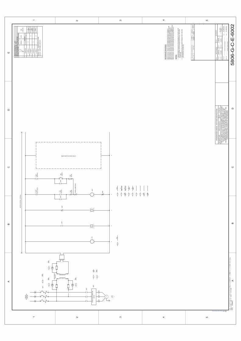
B. Combination Starters
1. Each starter within a MCC which supplies power to a motor shall be equipped with
motor circuit protectors (MCPs) and electronic overload protection in the starter to protect motors against overload. All MCC’s shall be provided with full digital
communication interface with the Locks Electrical Distribution Control System
(EDCS) for supervision purposes and if required, with the equipment controllers.
2. The MCP molded case circuit breakers shall have the withstand capacity specified in
Article 1.04 at 480 Volts for motor protection. The breaker shall provide adjustable
magnetic protection and shall be provided with pin insert to stop magnetic adjustment
at 1300% motor nameplate full load current in order to comply with NFPA 70.
3. The circuit breakers shall be manually operated, shall be quick-make, quick-break,
common trip type, and shall be of automatic-trip type. Circuit breakers shall be
Molded Case type conforming to IEEE C37.17 and shall be UL 489 listed. All poles of each breaker shall be operated simultaneously by means of a common handle. The
operating handles shall clearly indicate whether the breakers are in "On," "Off," or
"Tripped" position and shall have provisions for padlocking in the "Off" position. Personnel safety line terminal shields shall be provided for each breaker. The circuit
breakers shall be products of only one manufacturer, and shall be interchangeable.
Circuit breakers shall be provided with a push-to-test button and bell alarm contacts
that close on automatic operation only. The contacts shall be suitable for 125 VDC and shall reset when the breaker is reset.
4. Magnetic contactors shall be of the NEMA sizes as required by the load size
provided in the load list. The rating, performance and service characteristics shall conform to the requirements of NEMA ICS 2 for contactors with continuous current
ratings for the duty indicated. Contactors for motor control shall be rated for full-
voltage starting (Class A controllers). Contactors shall be suitable for at least 200,000
complete operations under rated load without more than routine maintenance. Contactors shall have air or vacuum arc extinguishing provisions. If air arc
extinguishing is provided, arc chutes and silver-to-silver contacts shall be easily
removable without dismantling other parts. The contactor shall operate without chatter or perceptible hum while energized. Coils shall be suitable for continuous
operation at +24 VDC circuits. Alternating current contactors shall be three-pole and
be insulated for 600 VAC and of the electrically operated, magnetically held type. Auxiliary contacts shall be mechanically operated by the starter contactors. The
quantity of contacts shall be as required by the Supplier’s design, plus a minimum of
two (2) normally open (N.O.) and two (2) normally closed (N.C.) contacts for the
Contractor's use.
5. The smallest starter size shall be NEMA Size 1.
Contract No. CMC-221428, Design and Construction of the Third Set of Locks
6. Overload protection shall consist of one (1) current sensor located in each phase
monitored by a microprocessor that yields a time-current curve closely paralleling that of motor heating damage boundary, accurate to 2%. Running overload
protection shall be DIP switch selectable for the specific motor full load amperes
within the starter range. Provide DIP switch selectable overload trip class of 10, 20
and 30.
7. Motor starters shall monitor current in each phase to provide phase loss and phase
unbalance protection, such that if the unbalance of any two phases is greater than
30% of the selected trip rating, a phase loss/unbalance trip occurs. Provide phase loss/unbalance protection, which requires no time delay for reset. A factory wired dry
output contact shall be provided for phase loss remote alarm indication.
8. Motor starters shall be provided with phase reversal protection and factory wired dry output contact for phase reversal remote alarm indication.
9. Motor starters shall provide ground fault protection. Ground fault protection shall be
a settable value in percent of the maximum continuous ampere rating. The ground
fault protection shall have a start delay and a run delay to prevent nuisance trip on starting.
10. Solid-state soft starters shall be provided for the loads as identified in the load list.
The solid-state soft starter shall be UL and CSA listed in the motor control center, and shall consist of an SCR-based power section, logic board and paralleling bypass
contactor. The paralleling bypass contactor shall be energized when the motor
reaches the full speed.
11. Each starter shall have an addressable communication card capable of transmitting
over an Ethernet port diagnostic/control to a communication network that shall be in
accordance with Employer's Requirements Section 01 81 26 (Communications,
Control, Safety, and Security Systems). The addition of a communication module shall not increase the size of the controller. Field buses shall be in accordance with
Employer's Requirements section 40 00 00 (Process System Integration) and all the
communication protocols shall be compatible with those of the EDCS. The starter shall be capable of transmitting the following control/diagnostic data:
a. On-Off and reset control functions
b. Status
c. Current in each phase
d. Voltage in each phase
e. Percent phase unbalance
f. Control voltage
g. Overload trip
h. Cause of trip indication
i. Trip current magnitude
j. Ground fault
Contract No. CMC-221428, Design and Construction of the Third Set of Locks
12. Buckets with starters shall be wired such that motor control cables are terminated on
two piece detachable terminal blocks to allow for easy bucket removal for maintenance purposes. Provide minimum of an additional eight installed spare
control terminals for future use.
13. All MCC starters and contactors shall have door-mounted red and green LED lights
to indicate starter and contactor status.
C. Circuit Breakers Assemblies
1. Circuit breakers shall be thermal magnetic, molded case, 480-volt, three pole, 60 Hz,
with solid state interchangeable trip units, sized to protect the supply cable and individual loads. Circuit breakers shall be built and tested in accordance with UL
489.
2. Each circuit breaker shall be provided with a trip alarm contact.
D. Incoming and Bus Tie Units and MCC Feeders
1. Incoming (main), bus tie and MCC feeder breakers shall be of the electrically
operated (EO) drawout power type constructed and tested in accordance with C37.13,
C37.17, C37.50, UL-1066 and UL-1558, rated to bus ampacity and insulation of 600V. They shall meet the following requirements:
a. Incoming breakers and feeder breakers serving as the incoming source of
downstream MCC’s (i.e, Water Saving Basin MCC’s) shall include all the characteristics of the Motor control units for wiring and communication.
Breakers shall be equipped with solid-state overcurrent trip devices with
communication capabilities and metering functions. Additionally, incoming feeders shall be provided with reverse power protection (32), equivalent to a
directional overcurrent (67) in reverse mode, with the solid state trip devices as
shown on the drawings. Feeder entrance provision shall be able to accept
multiple 500kcmil copper conductors per phase, or non-segregated phase bus duct or cable bus duct. Aluminum cable entrance terminals are not acceptable.
b. Bus tie breakers shall also be provided with solid-state overcurrent trip devices.
The tie breakers will be used as disconnecting devices; however, remote control provisions shall be provided.
c. Main and tie circuit breakers shall be provided with all provisions required for
LOCAL and REMOTE operation.
d. Current transformers (CT's) and sensors shall be provided as required for protection and metering purposes.
e. The racking mechanism shall have provisions for padlocking in the withdrawn
position.
f. Hardwired interlocks shall be provided on all MCC main and tie circuit breakers
to avoid LOCAL/REMOTE operation of the tie breakers without opening one of
the two main circuit breakers.
Contract No. CMC-221428, Design and Construction of the Third Set of Locks
2. The tie breakers shall always be on the “NORTH” MCC bus as shown on the
Drawings. The connection between each NORTH MCC tie breaker and the SOUTH MCC bus shall be using Non-Segregated Phase Bus Duct (NSPBD). Supplier shall
include within the scope of supply the required NSPBD sections which shall be
designed, manufactured and tested according to IEEE Std C37.23.
3. For the purpose of the bid, Supplier shall assume the following MCC bus tie connection lengths:
a. MCC’s in Electrical Rooms MR-G1 and MR-G4, 2000A ratings, and MR-G2
and MR-G3, 3200 A ratings (1 MCC NORTH and 1 MCC SOUTH) in each room:
1) 40 meters of straight run with 4 elbows.
b. MCC's in MR-WSB1 thru MR-WSB6, 1200A ratings in each room:
1) 10 meters of straight run and 2 elbows.
c. MCC’s in Electrical Rooms MR-V5, MR-V6, MR-V7 and MR-V8, 2000A
ratings (1 MCC NORTH and 1 MCC SOUTH) in each room:
1) 20 meters of straight run with 2 elbows.
4. Supplier shall install a circuit breaker on the bus tie section of each SOUTH MCC to
isolate the bus tie connection.
E. Power Monitoring Device
1. The devices shall comply with IEC 61000-4-30 Class A equipment, be
microprocessor based, for 3 phase circuits with configurable alarms, for use with
current transformers (CTs), potential transformers (PTs) and equipped with a power module as required for operation. CT's and PT's shall be provided with the MCC's.
2. Each main incoming breaker shall be equipped with a solid-state power monitor with
the following features:
a. Voltage: per phase, average and unbalance
b. Current: per phase, average and unbalance
c. Power: real, apparent, reactive and power factor
d. Frequency
e. Energy, 4 quadrant (bi-directional)
f. Voltage Harmonics (up to the 30th or higher)
g. Current Harmonics (up to the 30th or higher)
h. THD for voltage
i. THD for current
j. Power quality as per IEC 61000-4-30
k. Store in memory kW-hours, kVAR-hours, and kW demand (resetable)
l. kW-hour accuracy shall be 0.50% or higher
Contract No. CMC-221428, Design and Construction of the Third Set of Locks
m. Shall include an interface card to permit communication via Ethernet network for
remote monitoring and control
n. Shall have communication and protocol compatibility to the system described on
ACP ER Section 40 95 13.19 (Process Control Hardware for Electrical
Distribution Control Systems (EDCSs))
o. True rms sensing circuit shall be achieved by analyzing the secondary current signals received from the circuit breaker current sensors and display instant kVA,
kW, kVAR, power factor, voltage and current.
F. Station Service
1. Each MCC shall be furnished with a single phase, dry type, electrostatically shielded,
480-240/120V transformer. The transformer size shall be 30 kVA minimum, or as
indicated in the load list, with copper windings and shall conform to NEMA ST-20.
2. Each of the transformers shall be installed with primary and secondary thermal
magnetic circuit breaker protection, properly rated according to NFPA 70 and shall
feed a single-phase, 240/120V panelboard not located on the MCC.
G. Field Bus Communication
1. Motor Control Center assemblies shall be provided with a factory assembled field
bus communications network providing direct connectivity between MCC devices
and the Employer’s Electrical Distribution Control System (EDCS), using a network protocol to be defined upon selection of the control system supplier. MCC's shall be
provided with all the gateway devices required for the external communication.
2. The field bus network system installed in each MCC shall include a complete and tested cabling system standard. The cabling system shall include all splice and tap
connectors and terminating devices. The cabling system shall be rated for 600 Volt
insulation and include electrical shielding as per the fieldbus standard specification.
Non-standard, non-shielded flat cable will not be accepted.
3. Communications modules shall be provided at each device interfacing to the field
bus. The communications modules shall be installed in the unit device compartment
or bucket, and shall be direct-connected to the drop cable. Each device shall be provided with the appropriate factory fabricated cable for interfacing the
communications module with the associated device.
4. Port expanders shall be provided where required to permit multiple device
communications. The port expander shall be installed in the associated unit device compartment.
5. Motor control centers shall provide required 24 VDC power to adequately supply
power to all the control and communication devices in the MCC. The power supply shall be installed in an MCC unit with a disconnect switch, supplementary protection
and a cable tap box to prevent damage to/from other power supplies on the network.
Contract No. CMC-221428, Design and Construction of the Third Set of Locks
1. Space heaters with thermostatic control shall be installed to provide protection from the effects of moisture. Space heaters shall be furnished at the bottom of each
vertical section (including breaker cell and bus compartment) of the MCC's to
prevent condensation of moisture within the enclosures. The heaters shall be located
and thermally insulated such that no painted surface shall be damaged or discolored and the temperature of the heater will not burn someone if it was touched. Space
heater location shall not interfere with the normal entrance of cables in to the
sections. Space heater capacity shall be as required to maintain the compartment and section internal temperature above the dew point; however, minimum acceptable
rating is 50 watts at 120 V AC power.
I. Nameplates
1. Nameplates of laminated phenolic material (or agreed upon equivalent) with 3/16-
inch minimum height engraved letters shall be installed to designate the purpose of
all circuits, instruments, meters, relays, and fuses. Each starter, breaker or contactor
shall have a nameplate on the front of the cubicle door describing the load served.
2. Each motor control center shall have a 2-in. x 6-in. master nameplate with 3/8 in.
high engraved letters. The master nameplate shall be located at the top of the section
containing the incoming line terminals.
3. All characters shall be block type and square cut with black letters on a white
background. Contractor will furnish the required nameplate engraving list during the
detailed engineering phase.
4. Nameplates shall be fastened to the equipment with removable rustproof machine
screws.
J. Dynamic VAR Compensation
1. Supplier shall design and specify for the purchase and installation by others of the Dynamic VAR Compensation (DVC) equipment in accordance with the requirements
in Section 26 60 00 "Dynamic VAR Compensation" of the Employer's Requirements
and shall provide space in the MCC if DVC equipment is required,
K. Protection Settings
1. Contractor shall include in his offer the protection setting calculation for all
protection devices included in the MCC (i.e., trip units, 67). Fault current levels will
be provided by the Contractor.
L. Heavy Duty Safety Switches
1. Switches shall have mechanical lugs suitable for copper conductors and capable to
accept multiple 500 kcmil cables.
2. Switches shall have a handle capable to be pad-locked in the OFF position.
3. Switches shall have defeatable door interlocks that prevent door from opening when
the handle is in the ON position. Defeater mechanism shall be front accessible.
4. Switch assembly and operating handle shall be an integral part of the enclosure base.
5. Switches shall have deionizing arc chutes and line terminal shields.
Contract No. CMC-221428, Design and Construction of the Third Set of Locks
1. All interior and ferrous metal shall be cleaned and protected with corrosion protective
coating system as per IEEE C57.12.29 and Section 09 96 00 (Corrosion Control
Coatings) of the RFP.
2. The material shall receive rust inhibiting phosphatizing treatment and have an enamel finish per ANSI standards.
2.04 SOURCE QUALITY CONTROL
A. Factory Testing shall be as specified in the Employer’s requirements Section 01 40 00 (Quality Requirements), Item 1.10 (Quality Control and Verification of the Works).
B. Tests, Inspections
1. All MCC equipment shall be tested at the Supplier’s factory. The Supplier shall promptly remedy any deficiencies brought out by factory tests at no cost to the
Contractor.
2. The Contractor and Employer shall have the right to inspect all equipment covered by
this Specification and to witness any tests made on the equipment. Supplier shall make all necessary arrangements and provide all reasonable facilities and access for
inspection and observation of such tests. The assembly shall be fully assembled for
testing at factory. Equipment test at different factory locations is not acceptable.
3. The following production tests shall be performed on each motor control center
assembly in accordance with ANSI/IEEE Standard C37.20.1 and as follows:
a. Mechanical Operation Test: Mechanical operation tests shall be performed on the motor control center assemblies to ensure that all mechanical interlocks and
other mechanical parts function correctly and in accordance with this
Specification.
b. Sequence Test: Sequence test shall be performed to ensure that all devices in each particular functional sequence operate properly and in the correct order.
c. Control Wiring Continuity Test: Control wiring continuity tests shall consist of
verifying that the control wiring is in accordance with the wiring diagrams and this Specification.
d. Control Wiring Insulation Test: The control wiring shall be subjected to and
successfully withstand the tests for control wiring that are specified in this
Specification.
e. The MCC equipment and wiring shall be subjected to a one-minute test of at least
1500 VAC phase to ground at the factory after fabrication and assembly has been
completed.
f. Factory test reports shall be certified by the manufacturer or approved testing
laboratory and submitted following successful completion of the tests.
g. All MCC’s shall be UL listed and bear the UL label.
4. The non-segregated phase bus duct shall be tested in accordance with IEEE Std
C37.23.
Contract No. CMC-221428, Design and Construction of the Third Set of Locks
1. All routine and standard tests shall be in accordance with the applicable industry standards.
2. The Supplier shall furnish the Contractor with 30 days advance notification of final
assembly and testing and provide drawings documents, mill certificates, Material
Safety Data Sheets and a certificate of compliance.
PART 3 – EXECUTION
3.01 FIELD QUALITY CONTROL
A. The Supplier shall provide services of a qualified factory-trained manufacturer’s representative to assist the Contractor in installation and startup of the equipment
specified under this section. The manufacturer’s representative shall provide technical
direction and assistance to the Contractor in general assembly of the equipment, connections and adjustments, and testing of the assembly and components contained
herein. After the equipment is put in Service, Contractor will run a performance test on
the equipment under the Supervision of the Supplier to ascertain that it is performing
according to the warranty in every respect. Supplier shall promptly remedy any deficiencies brought out by this test at no cost to Contractor. The Supplier shall provide
three (3) copies of the manufacturer’s field startup report.
B. In addition to providing support during the installation, the Supplier shall provide support during the Pre-Commissioning Test and Commissioning Test up to issuance of the
Taking Over Certificate by Employer and Test After Completion two years after the date
of the Taking-Over Certificate as specified in the Employer’s Requirements Section 01 91 00 (Tests on Completion and Tests after Completion).
3.02 DEMONSTRATION
A. The Supplier shall provide training to the Employer as specified in the Employer’s
Requirements Section 01 79 00 (Demonstration and Training).
B. Upon completion of the installation, the Supplier shall instruct the Employer in the
operation and maintenance of the equipment.
END OF SECTION
THIS PAGE INTENTIONALLY LEFT BLANK
ATTACHMENT 1
THIS PAGE INTENTIONALLY LEFT BLANK
THIS PAGE INTENTIONALLY LEFT BLANK
Contract No. CMC-221428, Design and Construction of the Third Set of Locks


![24.941J / 6.543J / 9.587J / HST.727J The Lexicon …...– CV[+nas]C tend to contain just long V’s (M.Ohala 1973) – CVN tend to have short V’s, – Voiceless C shorten Vs in](https://static.documents.pub/doc/80x56/5f3b12110d0aee0b2e7e2541/24941j-6543j-9587j-hst727j-the-lexicon-a-cvnasc-tend-to-contain.jpg)


