Page 2USL, Inc. PSA-200U Instruction Manual 1st Edition. October, 2004
One Year Limited Warranty
★★★★★
USL, Inc. warrants that each product manufactured by it will be free from defects in material and workmanship under normal usage for a period of one (1) year after its purchase new from an authorized dealer. Our obligation under this warranty is limited to repairing or replacing any product or component which we are satisfied does not conform with the foregoing warranty and which is returned to our fac-tory, freight paid, or serviced by one of our authorized contractors. The foregoing warranty is exclusive and in lieu of all other warranties, whether expressed or implied. Such warranty shall not apply to any product or component (A) repaired or altered by anyone other than USL, Inc. or an authorized service contractor; (B) tampered with or altered in any way or subjected to misuse, negligence or accident or (C) which has been improperly connected, installed or adjusted other than in accordance with USL, Inc. instruction.
Page 31st Edition. October, 2004 USL, Inc. PSA-200U Instruction Manual
Page 4USL, Inc. PSA-200U Instruction Manual 1st Edition. October, 2004
Review the following safety precautions to avoid injury and prevent damage to this product. To avoid potential risk, use this product only as specified and only for the purpose described in the instruction manual.
To Avoid Fire and Personal Injury:• Use Correct Power Cable. Use only the power cable
provided. Insure that the AC power outlet is located near the product and is easily accessible.
• Use a Correctly Grounded Power Source. The Power Supply earth ground is established through the ground conductor in the power cable. To avoid the potential of electric shock, the ground conductor must be correct.
• Observe Source Ratings. To avoid risk of fire or elec-tric shock, the power source must be 110 - 240VAC, 50-60 Hz
• Do Not Operate this Product with Any Covers Opened or Removed.
• Avoid Exposed Circuitry. Do not attempt to open the Power Supply as its safety certification would be invalidated. The Power Supply is a non-repairable sealed device.
• Do Not Operate with Suspected Failures. If you suspect there is damage or malfunction with this product, call the factory.
• Do Not Attempt Repair. Only a trained factory ser-vice person is authorized to repair this product.
• Do Not Operate this Product Near Heat Sources. This product should not be located near heat sources such as radiators, heat registers, stoves, or other high temperature sources.
• Provide Proper Ventilation. The operating tempera-ture should be between 0° C and 50° C. The humidity should be <90% at +40° C or below and <60% at 41° C to 50° C. The cooling method is by convection.
• Keep Product Surfaces Clean and Dry. Disconnect the power cable from the power source before clean-ing. Do not use liquid cleaners or aerosol cleaners. Use a damp cloth for cleaning the outside of camera. Use lens cloth for lens cleaning.
• Do Not Push Objects Into Opening of this Product. Never insert objects into the product through open-ings.
• Do Not Operate In Wet or Damp Conditions.
• Do Not Operate In an Explosive Atmosphere.
• Prevent the Spilling of Liquids onto the System Components.
• Inspect the Power Cable and All Cables Prior to Use. Confirm that the power cable and other inter-connecting cables are free from damage.
• Be Especially Alert When Setting Up Product in Theaters. Establish adequate light. Position cables to avoid trip dangers. The tripod and camera box should be carefully and securely attached to each other. The tripod leg angles should be fully extended outwardly in three directions for maximum stability. The leg length extensions can be varied to accom-modate the inclination of the theater flooring.
General Safety Summary
Page 51st Edition. October, 2004 USL, Inc. PSA-200U Instruction Manual
The USL, Inc. Projection System Analyzer 200U (PSA-200U) is an advanced system for aligning and analyzing motion picture projection systems.The PSA-200U is a portable system that comes in a single, high-quality carrying case. The system primarily consists of a specialized camera, custom software, USB device and interface cables. It is designed for use with a laptop PC operating Windows 98SE, Windows ME, Windows 2000 or Win-dows XP.The PSA-200U greatly improves the qual-ity of projection system alignment and significantly reduces the time and effort involved. The PSA-200U displays the lumi-nance values for every part of the screen. It also indicates and accentuates variations in screen brightness by shading of the lap-top display. An optional feature also allows analysis and reporting of the weave, jitter and flicker components of the projected image. The PSA-200U can also be used as a spot meter. The standard luminance range is from three to 30 foot-Lamberts (10-100 candelas/square meter). With the addition of an optional ND1 neutral density filter, the range can be changed to 30 to 300 foot-Lamberts.All information measured and displayed can be saved in a report file suitable for hardcopy print out. A listing of all equipment for each theatre auditorium can be entered into the report along with any pertinent comments. The report files can be exported to a spread-sheet program such as Microsoft Excel. This makes the measurement data available for analysis of equipment performance and experimental results.
Power Cord (US: PC-USA, European: PC-EUR, Australian: PC-AUS)
Software CD ROM
Manual
OPTIONS
Weave and Jitter Software Upgrade (PS2-FWJ), includes RP-40 Test Film (SMPTE-35PA)
10-foot camera cable (PS2-C10), for use in projection booth.
Neutral Density Filter (PS2-ND1) 30-300 foot-Lamberts luminance range.
INTRODUCTION
Page 6USL, Inc. PSA-200U Instruction Manual 1st Edition. October, 2004
PSA-200U Component Identification
Page 71st Edition. October, 2004 USL, Inc. PSA-200U Instruction Manual
IMPORTANT! INSTALL SOFTWARE
BEFORE CONNECTING HARDWARE.
Before Connecting the USB Camera to the laptop PC, please install the PSA-200U software. This will insure that the correct drivers will be available for hardware con-nection.
Software Installation Software is provided on a CD-ROM with the PSA-200U.The software is compatible with Windows 98SE (second edition), Windows ME (mille-nium edition), Windows 2000 and Windows XP.
PSA-200U Application Installation:1. Insert the CD-ROM, labeled PSA200U
application into the CD drive.2. Click on the Start button then click on
the run icon. The “Run Dialog” box will appear.
3. Type in “d:/setup.exe”, then click on OK; a Welcome box will then appear.
4. Click install. A “Target Directory” dialog box will appear, along with the name of the directory where the PSA-200U program will reside. The default directory is c:\programfiles\usl\psa200.
5. Click on OK. A “Program Group” box will appear, along with the name of the program group, which will hold the icons for the PSA-200U program.
SETUP PROCEDURE
6. Click on OK. An “Installation Com-pleted” box will appear.
7. Click on OK. A window containing the PSA-200U shortcut icon and the uninstaller icon (used to remove the PSA-200U program from your laptop computer) will appear. (The PSA shortcut icon can be moved on to the desktop now.)
8. Remove the CD-ROM disk.
Connecting the Hardware After the software has been installed, plug the USB cable into an open USB port on your laptop computer. The device should be detected and installed automatically.
If you are running Windows XP, you may receive the following message.
You must choose “Continue Anyway” to allow the drivers to be installed. This will detect and install the device.
WARNING TO OWNERS OF MORE THAN ONE PSA-200U SYSTEMThe PSA-200U software contains calibration information. This information is matched to the hardware of the same serial number. For this reason, using the hardware from one system with the software from another will result in a loss of accuracy. Measurements obtained in this way are not guaranteed to be within specifications. It is recommended that users of multiple systems label the “target” and “program” directories by the serial number when installing them and run the software corresponding to the hardware being used.
Page 8USL, Inc. PSA-200U Instruction Manual 1st Edition. October, 2004
Hardware SetupThe laptop computer, the USB Interface Box and the Power Adapter are usually set up in the projection booth of the theater, while the camera may be set up in either the audi-torium or the projection booth. If the cam-era is set up in the center of the auditorium, the camera sees the movie screen exactly as the audience does. (The PSA-200U camera should be positioned at least one screen width back from the screen.) If the camera is set up in the projection booth, looking through the projection port, compensation for the vertical angle-of-view can be made in the software (see Camera on page 15).NOTE: The software must be installed be-fore the USB cable is inserted into the laptop computer.NOTE: The Power Adapter will accept any 50 or 60 Hz power source from 100 to 240 VAC. The power cord itself is specific to the region and type of outlet connector.1. The power cord of the power adapter
should be disconnected during hard-ware set-up.
2. Mount the camera on the tripod and set it either in the center of the audi-torium or in the projection booth.
3. Connect the camera cable from the camera to the USB Interface Box.
4. Connect the female DC output con-nector of the power supply to the PSA-200U USB Interface Box.
5. Connect the AC power cord of the Power Adapter to the Power Adapter and to an AC outlet.
6. Remove the lens cap from the camera lens, orient the camera and adjust the zoom control at the rear of the camera (see Fig. 1) so that the movie screen fills about 90% of the camera view-finder screen and is centered. (It may be necessary to turn on the projection lamp to provide adequate light for the camera positioning and zoom adjust-ment.)
(Fig. 1) Viewfinder Display
7. Turn on the laptop computer. 8. Access the PSA.exe program on the
laptop computer. The laptop computer display should show a 9 by 5 grid of luminance values (see Fig. 2). Across the top will be a toolbar with function key buttons which access various PSA-200U functions.
(Fig. 2) Luminance Grid (9x5)
Page 91st Edition. October, 2004 USL, Inc. PSA-200U Instruction Manual
NOTE: If the camera is not connected, an error message will be displayed. (See Troubleshooting on page 19.)9. Turn the projector on with no film
inserted. Turn the projection lamp on. Open the dowser to illuminate the screen. WARNING: Do not leave the dowser open for more than one (1) minute. Heat from the projection lamp light can damage the projector lens.
10. Press F3, or click on Camera View. The display should show the movie screen as seen by the camera (see Fig. 3). It should look centered on the laptop computer screen. The image of the movie screen should fill about 90% of the laptop computer screen and all edges of the movie screen should be visible, along with a darker border around the edges. If no border is visible, zoom out until the movie screen’s border appears. You can use the zoom control on the camera or the zoom control on the laptop computer (Camera View [F3]) screen, whichever is more convenient.
(Fig. 3) Camera View
11. Press F2, or click on Auto Align. This function automatically senses the edges of the movie screen image. It creates an artificial border for the lu-minance measurements. This border is a rectangle inset from the screen edges
by 5% of the screen dimensions. All screen luminance measurements are made within this border.
12. Press F4, or click on Luminance. The displayed grid will now show the ac-tual luminance readings for each of the 45 zones of the grid (Fig. 2). The shading of each zone should show the relative brightness with respect to the other zones, giving a good display of the light pattern for ease of lamp house adjustment.
NOTE: The PSA-200U and laptop computer require a warm-up period of at least two minutes before measurement readings are accurate.
Page 10USL, Inc. PSA-200U Instruction Manual 1st Edition. October, 2004
OPERATIONThis section describes the operation of the PSA-200U in detail. It is organized by specific activity for easy reference. These activities appear in the usual order they are performed when using the PSA-200U.
Automatic AlignmentManually adjust the camera angle and the camera zoom switch so that the theater screen appears centered in the camera’s viewfinder (see Fig. 3). Press F3, or click on Camera View. The image should appear centered in the laptop computer display. Adjust the zoom control so that the edges of the screen are visible in the laptop com-puter display. Now press F2, or click on Auto Align. The PSA-200U software will automati-cally sense the edges of the movie screen image and create an artificial border for the luminance measurements. This border is a rectangle inset from the screen edges by 5% of the screen dimensions. All screen lumi-nance measurements are made within this border. NOTE: The Camera View, Luminance and Spot Meter are the only functions that use the alignment border.
Manual AlignmentIn rare instances, when the lamphouse is severely misaligned, the automatic align-ment software will not be able to locate the screen edges. In this case, the manual alignment function must be selected. This function allows the user to manually set the borders of the screen area to be analyzed. First, press F3, or click on Camera View, then click on the “Alignment” menu, then on “Manual.” Position the mouse pointer on the top-left corner of the desired area, then click and drag the mouse pointer to the bottom-right corner of the area and click again. The manual alignment border and the previous alignment border will both remain on the screen. Now select “Camera View” again. A single alignment border, representing the manual alignment, should be present on the screen (see Fig. 4). The manual alignment border that is produced
must lie inside the image and not in the darker border surrounding it in order for a manual alignment border to work.
(Fig. 4) Manual Alignment
Measuring LuminanceFirst, use the Automatic or Manual Align-ment function. Next, press F4, or click on Luminance. The PSA-200U software breaks down the luminance of the projection screen into 45 (9 X 5) zones (see Fig. 2). A separate luminance value is measured and displayed for each zone. Each of these luminance val-ues is an average of 10 separate measure-ments taken at different places in that zone. The shading of each zone shows the relative luminance with respect to the other zones, giving a good display of the light pattern for ease of lamp-house adjustment. Zones are numbered, left to right, starting from the top, for reference. The status bar (located at the bottom of the screen) displays the zone that the mouse pointer is in, along with the average luminance and the center zone’s luminance.
Measuring IlluminationIt is possible to measure the incident light reaching the movie screen by switching from the “Luminance” mode to the “Lu-mens” mode. The screen dimensions and gain must be entered as described on page 15 (see “Lumens Mode” and Fig. 12). The Lumens mode displays the total screen il-lumination as well as the illumination for each segment of the display on a 3x3 grid or the 9x5 grid.
Page 111st Edition. October, 2004 USL, Inc. PSA-200U Instruction Manual
Using the Spot MeterThe Spot Meter function is useful in taking measurements of ambient light, reflected light and lens flare. While in Camera View (F3) or Luminance (F4), press F6, or click on the Spot Meter icon. Use the mouse to move to any part of the area being analyzed and the luminance value displays in the status bar at the bottom of the screen, along with the center luminance and the number of the zone the Spot Meter is in (see Fig. 5).
(Fig. 5) Spot Meter
Checking Weave and Jitter (Optional Feature)
The PSA-200U measures picture steadiness in terms of Weave and Jitter (or Jump). Weave is the residual horizontal motion of a projected image. Jitter is the residual vertical motion of the image. The software uses the image of the SMPTE test film RP 40 for calibration and measurements. (For information on measurements and accept-able values, please refer to SMPTE Recom-mended Practice # RP1-5-1995. The width of one square on the test pattern represents 0.5% weave. The vertical dimension of a square represents 0.94% jitter when the aspect ratio is 1.85 to 1.)
Procedure1. The loop of RP-40 test film should be
as long as practical. It is good practice to use a loop of 20 to 25 feet in length, passing the film from the projector to a platter roller and back. The minimum
practical loop length is about eight feet. Shorter lengths result in too short a time interval between splices for accurate measurements to be made. The algorithms of the weave and jit-ter measurements are iterative and averaging processes. They analyze the change in position of the squares as the film passes through the gate. The wide misalignments of a splice cause errors which must be evaluated and discarded. The longer the time between splices, the higher the per-centage of good data that is available for the analysis.
2. Use the “flat” lens of the projector, (1.85:1 for example), and enter the aspect ratio of the aperture in the “Program” set-up box of the “Settings” menu.
3. Position the camera approximately one screen-width back from the screen in the audience area of the auditorium. Center the screen image on the view-finder.
4. Run the loop of RP-40 test pattern film.
5. Press F3, or click on Camera View. Make sure that the RP40 test image is centered in the Camera View presenta-tion (see Fig. 6).
(Fig. 6) SMPTE Test Pattern
Page 12USL, Inc. PSA-200U Instruction Manual 1st Edition. October, 2004
6. Use the Camera View [F3] zoom con-trol to zoom in on the image until the wide pattern in the center of the frame fills nearly 3/4 of the Camera View in the horizontal direction. (See Fig. 7.)
(Fig. 7) SMPTE Test Pattern7. Press F7, or click on Weave & Jitter,
then press F3, or click on Camera View. A small red box will appear at the lower left of the laptop screen. This box indicates the area which the software analyzes in making the mea-surements. Two aspects of this box are important: (a) that it enclose only the checker-board-squares portion of the pattern and does not include any other graphics; and (b) the camera lens should be zoomed in far enough that the box encloses approximately three or four squares vertically.
8. Switch back to F7 to make the mea-surements. After approximately 10 to 20 seconds, the display should appear and present the initial readings (See Fig. 8). Depending on the length of the loop and the misalignment at the splice, it will take from one to four minutes for the results to reach the final values asymptotically
9. Our research has shown that the PSA will present stable, consistent read-ings within one minute from a 20-foot test loop. It can take up to four or five
minutes for final values to be reached when shorter loops are used.
10. The PSA-200U is calibrated for use with SMPTE test film RP 35-PA/ RP-40 for 35mm projectors. If measurements are made using SMPTE 70-PA film on 70mm projectors, the weave and jitter readings will be 10% higher than the actual values.
11. Press or click on the Save bar at the upper right of the screen to save the figures to the report.
(Fig. 8) Weave
Checking Flicker (Optional Feature)1. To measure flicker of the light source,
the projector should be running with-out film in the gate. The screen image should fill 90% of the raster in “Camera View” (F3).
2. Press F8, or click on Flicker (see Fig. 9). This function displays the flicker as a percentage of the amplitude of the desired component (the 48 or 72 light pulses per second component). The graph displays the frequency and am-plitude of the flicker components as a troubleshooting aid.
3. Flicker values of 1% to 3% are normal. Readings of 5% or more usually indi-cate a problem related to the Xenon bulb or lamp house.
Page 131st Edition. October, 2004 USL, Inc. PSA-200U Instruction Manual
(Fig. 9) Flicker
Report FunctionThis function allows all measurement data and equipment configuration to be sum-marized in a concise report suitable for printing or exporting to a database.
Saving Data to the ReportLuminance and other data can be saved to the report. Select the function to be saved so that the data shows on the screen, then press the S key on the keyboard or click on the Save button on the toolbar. You can also select “Save” from the “View” menu to save data to the report. To overwrite exist-ing data on the report, select the desired function and save it to the report. The old data for that function will be replaced with the new data.
Adding Text to a ReportOnce data has been saved to a report, text information about the equipment and the measurements can be added. First, press F9, or click on Report, to view the saved data (see Figs. 10a and 10b). Press F9 again, or click again on Report, to bring up the “Report Edit” dialog box (see Fig. 11). Press the tab key to move through the different text entry blocks or click on the desired text entry block with the mouse, then enter the text. When you are finished, press the enter key or click on the OK button. The Clear Data button deletes all of the text of the report. The Cancel button deletes all
of the text of the report and returns to the PSA-200U report screen.
(Fig. 10a) Report - Top
(Fig. 10b) Report - Bottom
(Fig. 11) Report Edit
Page 14USL, Inc. PSA-200U Instruction Manual 1st Edition. October, 2004
Deleting all Data and Text from a ReportTo delete all data from the report, includ-ing text, select “New” from the File menu. A message will appear which asks whether you want to save the changes made to the report. Selecting “Yes” will bring up the “Save As” dialog box, enabling you to save the current report before going to a new, blank report. Selecting “No” will delete all report contents.
Saving a Report to a FileSelect “Save As” from the File menu. Enter a name for the file. Select the drive and di-rectory. Press the enter key or click on the OK button.
Printing a ReportSelect “Print” from the File menu. A print dialog box will appear. Press the enter key or click on the OK button.
Viewing a Saved Report fileThe PSA-200U program must be running in order to view a report. Select “Open” from the File menu. Select the file name and press the enter key or click on the OK button.
Deleting a Previously Saved ReportFirst, exit the PSA-200U program. Using My Computer or Windows Explorer, double-click on the drive where the PSA-200U files are stored. Double-click on the PSA-200U folder or other directory and folder (where files are saved). Select the .rpt file to be deleted, then press the Delete key or select File, then “Delete.” WARNING: Care should be taken to insure that only the intended files are selected for deletion.
Creating a Report with the same (or similar) file name as a previously saved report
Select “Open” from the File menu. Choose the previously saved file and click on OK. Save the new data to the report, then make any necessary changes in the text. Select “Save As” from the File menu. Enter the file name for the new report, then click on OK.
Creating Multiple Reports with the same (or similar) file name
After saving the first report, be sure not to select “New” from the File menu (this clears the report contents but does not delete the last saved report file). Instead, save the new data onto the first report and make any nec-essary changes in the text. Select “Save As” from the File menu. Enter the new file name, then click on OK. (Entering the same name as the first report instead of a new one at this point will overwrite the first report.)
Menu BarFile
This menu includes all the standard func-tions as well as two specialized ones to al-low the export of report information.
SettingsThis menu allows choice of options for three sections of the software, Program, Export and Authorization. Under Program, optional settings for the display and measurements are established (see page 15).The Export section provides options for the export format of the report functions.The Authorization function allows the up-grading of software in the field. The user enters an authorization code (provided by contacting USL) into the dialog box to implement software upgrades.
AlignmentRefer to page 10.
ViewThis menu feature allows the selection of each of the main functions of the PSA-200U. It also provides an alternate way of saving data on the screen to the report.
ReportThis menu item selects the Report function.
HelpThis item displays the PSA software version number. The Help portion has not yet been implemented.
Page 151st Edition. October, 2004 USL, Inc. PSA-200U Instruction Manual
value for the center zone is displayed and the rest of the zones show the luminance value as a percentage of the center value reading. It is possible to measure the total light incident on the screen by switching to the Lumens mode. To do so, check the box la-beled “Lumens Mode” and enter the screen height, width and gain. (See Fig. 12).
(Fig. 13) Luminance Grid 9x5
(Fig. 14) Luminance Grid 3x3A check box is provided for the choice of luminance data being displayed rapidly as measured or after filtering. The filtered data is updated more slowly and is easier to read.CameraThis section sets the measurement range of the camera and display. It also will adjust the data to compensate for the vertical angle-of-view when the camera is positioned in the projection booth.The nominal measurement range of the PSA-200U is three to 30 foot-Lamberts. With the addition of an optional ND1 neutral density filter, the range can be changed to 30 to 300
ProgramThe Program section controls values for the display and measurement functions (see Fig. 12).
(Fig. 12) Program SetupDisplay Five shades of gray are used to show bright-ness differences among the zone squares. The “foot-Lamberts per gray step” value sets the number of foot-Lamberts variation between steps or displayed shades of gray. A value of one is the default value and is proper for most applications.“Fit display contrast to image contrast”: This asks the software to maximize the contrast of the display and to have it follow the camera video closely. This is normally checked.Weave and JitterIf the Weave and Jitter option is included and such measurements are to be made, the screen aspect ratio should be inserted here. Correct calculation of the results is dependant upon the aspect ratio.LuminanceThis section allows choice of display win-dow type, either 9x5=45 zones (see Fig. 13) or 3x3=9 zones (see Fig. 14). In the 9x5 dis-play, the luminance value is displayed for each zone. In the 3x3 display, the luminance
Page 16USL, Inc. PSA-200U Instruction Manual 1st Edition. October, 2004
foot-Lamberts. The PSA camera is normally set to read luminance in the audience area. If the camera is situated in the projection booth, there is a vertical angle between the audience view of the screen and the view from the projection booth. This causes the apparent centering of the light pattern on the screen to move upward. If this appar-ent centering error is not corrected, the lamphouse adjustments will be in error. The selection box in this section allows you to input the approximate vertical angle be-tween the audience view and the projection booth view so that the error can be compen-sated. The precise angle does not have to be measured. If the angle that is estimated and entered is within five or 10 degrees of the actual value, the vertical centering will be within a few percent.UnitsThis section provides a choice between English and metric units of luminance.
Exporting FilesThe PSA-200U has single and multiple report file handling features which includes the capability of combining previously saved report files and storing such combined files in an export format (suitable for import into spreadsheet programs such as Microsoft Excel). This file handling feature couples the PSA-200U cinema analyzer to the power and utility inherent in data analysis programs.
Export Features• Data export options are selected through
the “Export Options” dialog box under the main menu option, “Settings”.
• Maximum number of report files selectable for export (at one time) is 3000.
• Using the “Save As” option under “File” on the main menu to save report files will automatically add the number “1” to the end of the file name. Subsequently, each time the “Save As” option is used to save a report file the numeric value will increment by one. For example (Cinema1.rpt) would be incremented to (Cinema2.rpt) this allows
easy identification of report files needed for export into a “CSV” file format. The available export options are explained in the following paragraphs, in the order that they appear in the ‘Export Options” dialog box. (See Fig. 15 and Fig 16.)
File TypeThe “File Type” option allows you to save data from multiple reports to a single file. For example, each time a luminance data set is captured from the luminance screen, a report file with the (.rpt) extension is cre-ated. Each of these report files or data sets can then be merged into a single report. The data report file created uses the ex-tension “CSV”. The “CSV” file is a “comma separated value” file, which can be directly imported into a spreadsheet program such as Microsoft Excel, or a database program such as FileMaker Pro.
Export FormatThe format of the data file has several op-tions including:
• All information is formatted on a single row.
• All information is laid out in cells in a horizontal row.
• Luminance information in a single row.
• Field names are inserted into the data structure.
• Data laid out in rows of 45 cells instead of a 9X5 Cell matrix.
Exportable Data FieldsEach of the main data fields from the report has the option of being included in the data export file. The optional fields include:
• The report header, which in-cludes the theater name, screen name, date, technician and serial number of the PSA used to take the measurements.
• Luminance Data• Weave and Jitter measurements
Page 171st Edition. October, 2004 USL, Inc. PSA-200U Instruction Manual
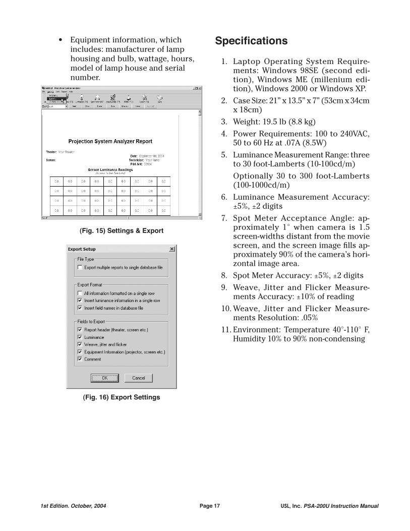
• Equipment information, which includes: manufacturer of lamp housing and bulb, wattage, hours, model of lamp house and serial number.
(Fig. 15) Settings & Export
(Fig. 16) Export Settings
Specifications
1. Laptop Operating System Require-ments: Windows 98SE (second edi-tion), Windows ME (millenium edi-tion), Windows 2000 or Windows XP.
2. Case Size: 21” x 13.5” x 7” (53cm x 34cm x 18cm)
3. Weight: 19.5 lb (8.8 kg)4. Power Requirements: 100 to 240VAC,
50 to 60 Hz at .07A (8.5W)5. Luminance Measurement Range: three
to 30 foot-Lamberts (10-100cd/m) Optionally 30 to 300 foot-Lamberts
(100-1000cd/m)6. Luminance Measurement Accuracy:
±5%, ±2 digits7. Spot Meter Acceptance Angle: ap-
proximately 1° when camera is 1.5 screen-widths distant from the movie screen, and the screen image fills ap-proximately 90% of the camera’s hori-zontal image area.
8. Spot Meter Accuracy: ±5%, ±2 digits9. Weave, Jitter and Flicker Measure-
ments Accuracy: ±10% of reading10. Weave, Jitter and Flicker Measure-
ments Resolution: .05%11. Environment: Temperature 40°-110° F,
Humidity 10% to 90% non-condensing
Page 18USL, Inc. PSA-200U Instruction Manual 1st Edition. October, 2004
PSA-200U Block Diagram
Page 191st Edition. October, 2004 USL, Inc. PSA-200U Instruction Manual
Troubleshooting The PSA-200U
Camera Not Found Error MessageIf your laptop displays the following error message (See Fig. 17), you need to...
Fig. 171. Shut the software off. 2. Disconnect power to camera and USB
cables.3. Re-connect all power and USB ca-
bles.4. Re-start the software and try again.If you still receive the error message please contact USL at (805) 549-0161 for technical support.
Luminance values are offIf the Luminance values are off, they will be off by a factor of 10. Check the Camera Range (Settings in the Program menu). Check to see if the neutral density filter is attached to the camera lens if you have a unit with the 30 - 300 foot-Lamberts (100 - 1000 cd/m2) option. (See the Program sec-tion for details on correct operation of the Camera Range settings.)
Computer message: Alignment Error!Manually adjust the camera angle and the camera zoom switch so that the image ap-pears centered in the camera’s viewfinder. Press F3, or click on Camera View. The im-age should appear centered in the computer display. Adjust the zoom switch on the cam-era or the W / T with the mouse in “Camera View” so the edges of the image are visible in the computer display. Now press F2, or click on Auto Align. If the error message in Fig. 18 appears again, try using the Manual Alignment function. If you cannot fix the problem, call us for technical support.
Fig. 18
Computer message: Weave and Jitter Warning - Screen luminance may be too high/low for accurate measurement
Verify that you have at least six to 18 foot-Lamberts of light from the lamp house. If you cannot fix the problem, call us for technical support.
Weave and Jitter measurements are not constant
The initial period that the PSA takes to sample the projected image is 30 seconds. When this occurs, the Weave and Jitter read-ings will be high or zero for a few seconds until they are updated. This is an errone-ous reading which is normal and should be ignored. The Weave and Jitter function should be left to run for two minutes in or-der to obtain enough samples of the frame to recognize samples of the film splice. The film splice samples will then be discarded automatically and will not be included in the analysis. If you are having problems that do not seem to be due to this, call us for technical support.
Weave and Jitter measurements do not seem to be accurate
Make sure the camera is zoomed in on the small squares of the RP40 test pattern (see Fig. 6). The camera should be aimed at the center of the test pattern and the Analysis Square (in the bottom left corner) should be trained only on the small black and white squares of the RP40 test pattern. Be sure that the projector is properly focused on the image. The pattern in the center of the screen, generated by the Weave and Jitter test film, cannot be used for analysis.
Page 20USL, Inc. PSA-200U Instruction Manual 1st Edition. October, 2004
Zooming in or out too far will cause errors in readings.
No power to cameraCheck power adapter connections. If there is still no power, verify that the power adapter indicator is lit. If the power adapter is working, check the camera cable con-nections, and the USB Adaptor Box cable connections. If there is still no power, the camera or camera cable may need repair. Call us for technical support.
Camera viewfinder is dark but camera power indicator light is on
Make sure the camera lens cap is removed from the camera lens. If the viewfinder is still dark, make sure the camera is receiv-ing at least five foot-Lamberts of light. If the viewfinder is still dark, the camera may need repair. Call us for technical support.