Hamilton Place, Inc. letter . . . . . . . . . . . . .17 II. MIRO INSTALLATION MRTI Inc. Rooftop Installation Specifications . . . . . .19
III. CONDUIT SUPPORTS (Conduit and Condensate) 1. Model 2.5-Conduit Support-2 Model 2.5-Conduit Support-5 Model 2.5-Conduit Support-7 and Model 2.5-Conduit Support-12 . . . . . .20 2. Model 12-Base Strut-7 (SS or HDG) Model 16-Base Strut-7 (P, SS or HDG) Model 16-Base Strut-12 (P) Model 20-Base Strut-7 (P) and Model 20-Base Strut-12 (P) . . . . . . . .25 IV. PIPE SUPPORTS (Gas and Mechanical) Polycarbonate: 1. Model 1.5 . . . . . . . . . . . . . . . . . . . . . .34 2. Model 3-R-2 and Model 3-R-4 . . . . . .36 3. Model 3-RAH-7 and 3-RAH-12 . . . . .39 4. Model 4-R, 4-RAH-7 and 4-RAH-12 . . . .42 5. Model 5-R, 5-RAH-7 and 5-RAH-12 . . . .46 6. Model 6-RAH-7 and 6-RAH-12 . . . . .50
Steel: 1. Model 3-RAH-7 (SS or HDG) . . . . . . .53 2. Model 4-RAH-7 (SS or HDG) . . . . . . .56 3. Model 6-RAH-7 (SS or HDG) . . . . . .59 4. Model 6-RAH-RS (SS or HDG) . . . . .62
DUCT, CABLE TRAY AND MECHANICAL SUPPORTTYPICAL DUCT CONFIGURATION
Pg. 90
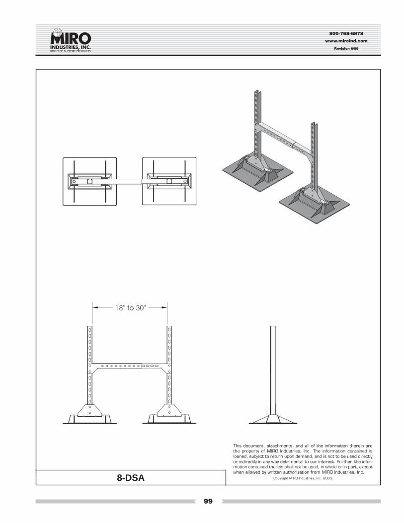
8-DSA
Pg. 99
CROSSOVER, WALKWAY, RAMP, & PLATFORM SYSTEMS
CROSSOVER
Pg. 106
WALKWAY & PLATFORM
Pg. 107
Square Duct Rectangle Duct Round Duct
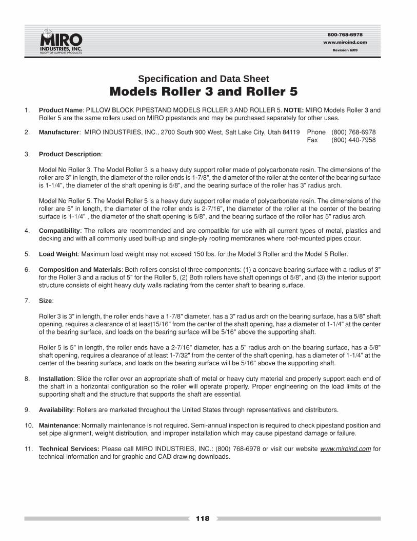
ACCESSORIESROLLERS
Pg. 119
1.5 PIPESTRAP
Pg. 121
3-R-2 PIPESTRAP
Pg. 122
4-RAH PIPESTRAP
Pg. 124
6-RAH PIPESTRAP
Pg. 125
UNI-FLEX SUPPORTSM-SS
Pg. 131
M-CB
Pg. 131
PAN HEADSCREW
Pg. 129
OCTAGONWASHER
Pg. 129
M-RBS
Pg. 129
3/8"ALL THREAD
Pg. 130
UNI STRUT
Pg. 130
M8UFS
Pg. 127
SUPPORT PAD & DECK PLATES
SUPPORTPAD
Pg. 109
DECKPLATES
Pg. 111
1.5 SPACER
Pg. 113
3-R SPACER
Pg. 116
3-R BRACKET
Pg. 126
RAMP
Pg. 107
3-R-4 PIPESTRAP
Pg. 123
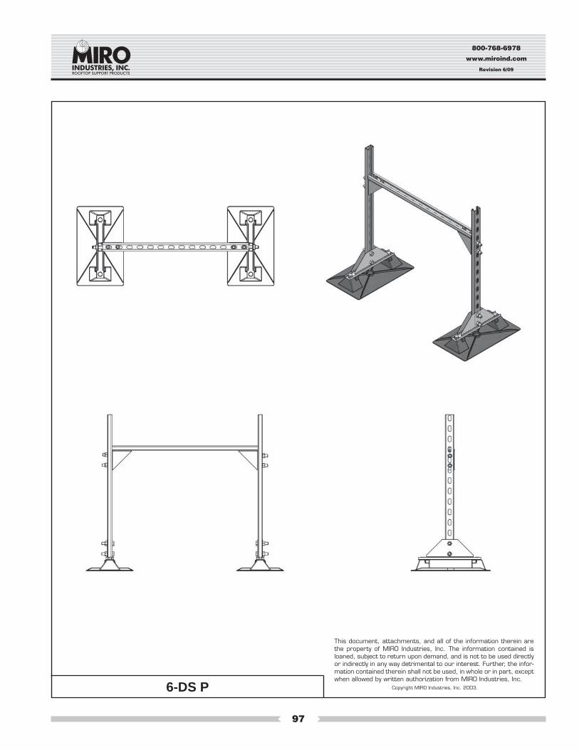
6-DS HDG & SS
Pg. 98
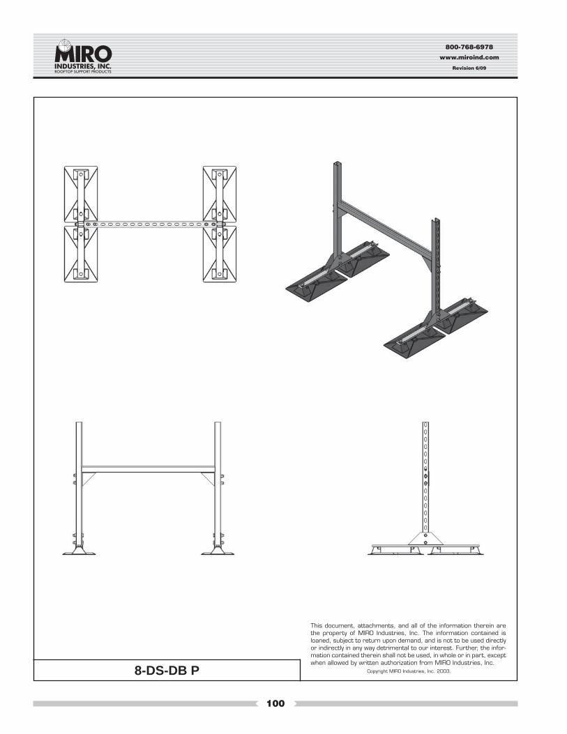
8-DS-DB P
Pg. 100
MECHANICALSUPPORTS
Pg. 104
Light Duty Heavy Duty
8-DS-SB P
Pg. 101
8-DS HDG & SS
Pg. 102
4-DSA 12x12
Pg. 93
6-DSA
Pg. 96
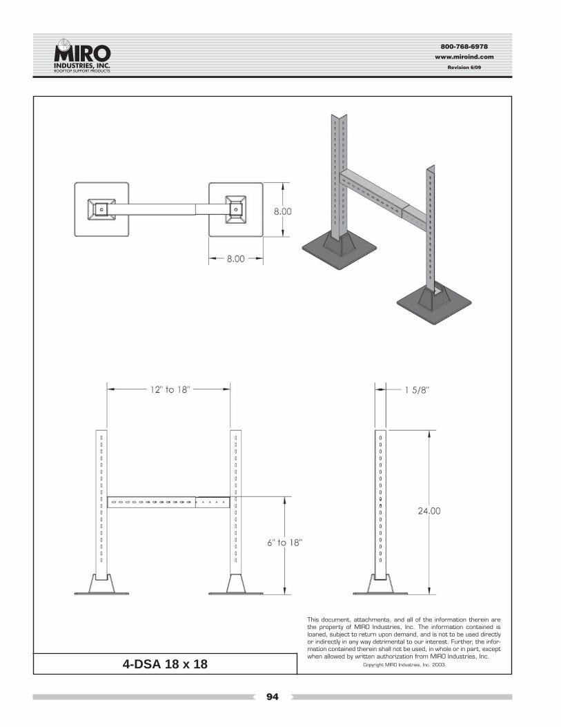
4-DSA 18x18
Pg. 94
800-768-6978
www.miroind.com
Revision 6/09
20
Maximum Pipe Size:2.5" Inside diameter3" Outside diameter
Specification and Data SheetModel No. 2.5-Conduit Support-2Model No. 2.5-Conduit Support-5Model No. 2.5-Conduit Support-7Model No. 2.5-Conduit Support-12
1. Product Name: PILLOW BLOCK PIPESTAND MODELS 2.5-Conduit Support-2, 2.5-Conduit Support-5, 2.5-Conduit Support-7and 2.5-Conduit Support-12. NOTE: Pillowblock pipestand model numbers correspond to usual pipe names. Pipe that is called2.5" pipe has a 2.5" inside diameter and a larger outside diameter. Model 2.5-Conduit Supports will hold all usual and customary2.5" and smaller pipe sizes, referring to the inside diameter. The maximum outside dimension of the pipe or conduit the Model 2.5Conduit Support will hold is 3" diameter.
2. Manufacturer: MIRO INDUSTRIES, INC., 2700 South 900 West, Salt Lake City, Utah 84119 Phone (800) 768-6978Fax (800) 440-7958
3. Product Description: A pipe support with “strut” used to support roof-mounted electrical conduit, solar piping, gas pipes, and othermechanical piping. Unique design absorbs thermal expansion and contraction of pipes thus preventing damage to the roof mem-brane. Pipes rest on a strut system which is made of hot-dip galvanized steel. The pipe support base is made of polycarbonateresin, and all other metal parts are made of hot-dip galvanized or stainless steel. Pipestand will accommodate up to 2.5 pipe (insidediameter) or up to 3" outside diameter pipes.
4. Product Performance: This strut and shape of the supporting base serve to keep the pipestand roller system directly beneath thepipe without binding and allows for some lateral expansion of the piping system. The base is gently rounded to allow movementupon the roof to prevent gouging the roof membrane. Clearance above the roof for the 2.5-Conduit Support-2 is 2.5 inches, the 2.5-Conduit Support-5 is adjustable from 3.25 inches to 5 inches. Clearance for the 2.5-Conduit Support-7 is adjustable from 3.25 to7.50 inches. Clearance for the 2.5-Conduit Support-12 is adjustable from 5.5 to 12 inches. More than one conduit or pipe may beganged on the pipe support and attached with typical pipe clamps or clips so long as the total load weight per support does notexceed 100 pounds.
5. Compatibility: Pillow Block Pipestands are recommended for use on and are compatible with all current types of decking and withall commonly used built-up and single-ply roofing membranes where roof-mounted pipes occur.
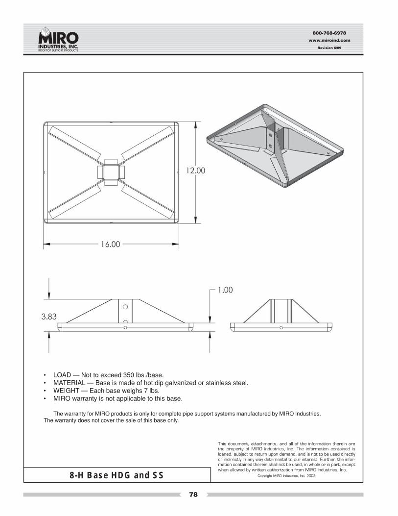
6. Load Weight: Maximum load weight may not to exceed 100 lbs. per pipestand.
7. Composition and Materials: The pipestand consists of two major components: (1) A one-piece polycarbonate roof deck basehousing and, for the 2.5-Conduit Support, 3/8" diameter all thread are connected to the base to adjust the height of the strut, and (2)a 12" by 5/8" by 13/16" hot-dip galvanized strut to support the attached conduit or pipe. Carbon black is added to the polycarbonateresin for UV resistance and protection.
8. Size: The deck base is 7.50" by 10" or the 2.5-CS-12 is 9" by 15.25" and the strut is 1-5/8" by 13/16" and 12 inches long. 2.5-Conduit Support has a maximum pipe clearance of 2.5", 5", 7" and 12" from bottom of pipe support.
9. Installation: (1) Center the pipestand beneath the pipe so that the strut allows the pipe to be squarely over the pipestand. (2) Adjustthe pipestand to the desired height and even load with other pipestands. Make certain the strut is level. (3) Set the pipe in thepipestand without dropping or causing undue impact. An additional sheet of roofing material, a traffic pad, or a MIRO Deck Plateshould be installed beneath the pipestand. For built-up roofs, all loose aggregate from an area 15" square should be removed fromthe area directly beneath the pipestand and then follow the installation directions set forth above. Care should be taken to installeach pipestand so it supports a proportional and equal amount of weight at each pipestand.
OPTIONAL METHOD OF INSTALLATION (Not recommended): Where code requires or as desired, the pipestands may be at-tached to the roof by appropriate and compatible rooftop fasteners.
10. Spacing: Manufacturer’s recommended spacing is not to exceed 10 foot centers depending upon the load. Do not exceed 100 lbs.load weight and make certain each pipestand is adjusted in height to even load.
11. Availability: Pillow Block pipestands are marketed throughout the United States through representatives and distributors.
12. Maintenance: Normally maintenance is not required. Semi-annual inspection is required to check pipestand position and set pipealignment, weight distribution and improper installation which may cause pipestand damage or failure.
13. Technical Services: Please call MIRO INDUSTRIES, INC.: (800) 768-6978 or visit our website www.miroind.com for technicalinformation and for graphic and CAD drawing downloads.
800-768-6978
www.miroind.com
Revision 6/09
21
2.5-Conduit Support-2
This document, attachments, and all of the information therein arethe property of MIRO Industries, Inc. The information contained isloaned, subject to return upon demand, and is not to be used directlyor indirectly in any way detrimental to our interest. Further, the infor-mation contained therein shall not be used, in whole or in part, exceptwhen allowed by written authorization from MIRO Industries, Inc.
Copyright MIRO Industries, Inc. 2003.
800-768-6978
www.miroind.com
Revision 6/09
22
2.5-Conduit Support-5
This document, attachments, and all of the information therein arethe property of MIRO Industries, Inc. The information contained isloaned, subject to return upon demand, and is not to be used directlyor indirectly in any way detrimental to our interest. Further, the infor-mation contained therein shall not be used, in whole or in part, exceptwhen allowed by written authorization from MIRO Industries, Inc.
Copyright MIRO Industries, Inc. 2003.
800-768-6978
www.miroind.com
Revision 6/09
23
2.5-Conduit Support-7
This document, attachments, and all of the information therein arethe property of MIRO Industries, Inc. The information contained isloaned, subject to return upon demand, and is not to be used directlyor indirectly in any way detrimental to our interest. Further, the infor-mation contained therein shall not be used, in whole or in part, exceptwhen allowed by written authorization from MIRO Industries, Inc.
Copyright MIRO Industries, Inc. 2003.
800-768-6978
www.miroind.com
Revision 6/09
24
2.5-Conduit Support-12
This document, attachments, and all of the information therein arethe property of MIRO Industries, Inc. The information contained isloaned, subject to return upon demand, and is not to be used directlyor indirectly in any way detrimental to our interest. Further, the infor-mation contained therein shall not be used, in whole or in part, exceptwhen allowed by written authorization from MIRO Industries, Inc.
Copyright MIRO Industries, Inc. 2003.
800-768-6978
www.miroind.com
Revision 6/09
25
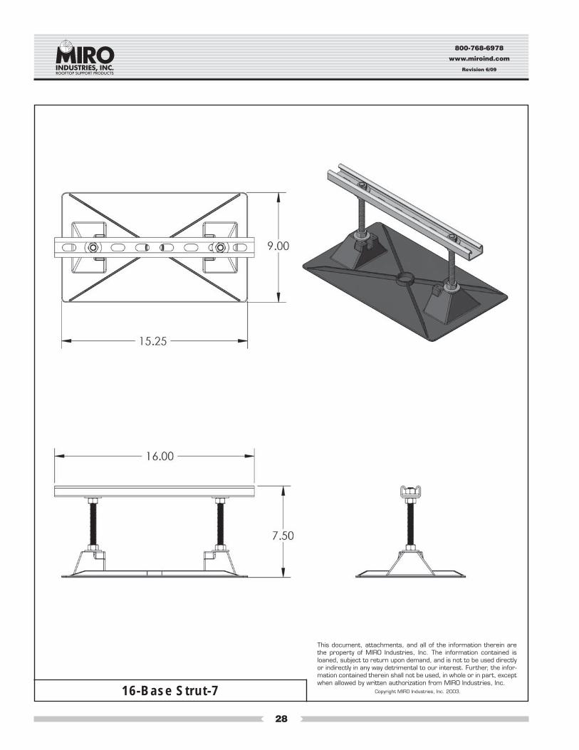
Specification and Data SheetModel Nos. 12, 16 and 20 Base Strut-7
Model Nos. 16 and 20 Base Strut-12(Numbers 12, 16 and 20 designate length of strut on support)
2. Manufacturer: MIRO INDUSTRIES, INC., 2700 South 900 West, Salt Lake City, Utah 84119 Phone (800) 768-6978Fax (800) 440-7958
3. Product Description: A pipestand with a strut and clamp pipe support system used for ganging roof mounted gas pipes, electricalconduit, solar piping and other mechanical piping. Unique design absorbs thermal expansion and contraction of pipes thus preventingdamage to the roof membrane. Pipes rest on a 12"or 16" length of strut which is mounted on the base. The pipes can then be fastenedby using typical clamps locked to the strut. The pipe support base is made of stainless steel, hot-dip galvanized steel, or polycarbonateresin; and the strut and hardware are made out of hot-dip galvanized or stainless steel.
4. Product Performance: As daytime temperatures warm the roof membrane and the mechanical pipe network found on the roof, the pipenetwork expands and moves over the roof. When the roofing membrane and pipe network cools, the process is reversed. With adifference of 20 degrees F. between nighttime and daytime temperatures, 100 ft. of 1" steel pipe may move as much as .25 inches perday. The base to which the strut and supported pipe are affixed is gently rounded to allow movement upon the roof to prevent gougingthe roof membrane. The base strut allows for movement without damaging the roof membrane.
5. Compatibility: Pillow Block Pipestands are recommended for use on and are compatible with all current types of decking and with allcommonly used built-up and single-ply roofing membranes where roof-mounted pipes occur.
6. Load Weight: Maximum load weight not to exceed 150 lbs. per steel pipestand, and 125 lbs. per 16-Base Strut-7 and 16-Base Strut-12 and 250 lbs. per 20-Base Strut-7 and 20-Base Strut-12.
7. Composition and Materials: The pipestand consists of two major components: (1) A one-piece stainless steel, hot-dip galvanized steelor polycarbonate resin support base, and (2) a single or double 12", 16" or 20" piece of galvanized, steel, strut connected with stainlesssteel 1/2" or 3/8" diameter all thread to each base. Carbon black is added to the polycarbonate resin for UV resistance and protection.
8. Size: The Pillow Block Pipestand Base Strut Models (Adjustable Height) are made as follows:
Polycarbonate:16-Base Strut-7: The deck base is 9" by 15.25", has a maximum bar length of 16", and can adjust in height from a low of 4" to a highof 7.5" in elevation above the roof membrane. The 16-Base Strut-12" has a deck base of 9" by 15.25" and is adjustable up to 12".20-Base Strut-7: The deck base is 16" by 18", has a maximum bar length of 20", and can adjust in height from a low of 4.5" to a highof 7.5" in elevation from bottom of pipe support. The 20-Base Strut-12" has a deck base of 16" by 18" and is adjustable up to 12".Steel:12-Base Strut-7: The deck base is 12" by 16" , has a maximum bar length of 12", and can adjust in height from a low of 3.5" to ahigh of 7.5" in elevation from bottom of pipe support.16-Base Strut-7: The deck base is 12" by 16" , has a maximum bar length of 16", and can adjust in height from a low of 3.5" to ahigh of 7.5" in elevation from bottom of pipe support.
9. Installation: (1) Center the pipestand beneath the pipe so that the strut is squarely over or under all lines of pipe. If more than one pipeis being supported, adjust for even distribution of weight. (2) Adjust the pipestand to the desired height and even load with otherpipestands. Make certain the strut bar is level. (3) Set the pipe in the pipestand without dropping or causing undue impact. If desired, anadditional sheet of roofing material, a traffic pad, or a MIRO Deck Plate can be installed beneath the pipestand. For built up roofs, allloose aggregate from an area 20" square should be removed from the area directly beneath the pipestand and then follow the installa-tion directions set forth above. Care should be taken to install each pipestand so it supports a proportional and equal amount of weight.
OPTIONAL METHOD OF INSTALLATION (Not Recommended): Where code requires or as desired, the pipestands may be attached tothe roof by appropriate and compatible rooftop fasteners through holes then drilled in the bottom of the pipestand pitchpan at the time ofinstallation.
10. Spacing: Manufacturer’s recommended spacing should not exceed 10 foot centers depending upon the load. Do not exceed loadweights designated above and make certain each pipestand is adjusted to even load at each pipestand throughout the roof system.
11. Availability: Pillow Block Pipestands are marketed throughout the United States through representatives and distributors.
12. Maintenance: Normally maintenance is not required. Semi-annual inspection is required to check pipestand position and set pipealignment, weight distribution and improper installation which may cause pipestand damage or failure.
13. Technical Services: Please call MIRO INDUSTRIES, INC.: (800) 768-6978 or visit our website www.miroind.com for technical informa-tion and for graphic and CAD drawing downloads.
12" long strut16" long strut20" long strut
800-768-6978
www.miroind.com
Revision 6/09
26
12-Base Strut-7 SS
This document, attachments, and all of the information therein arethe property of MIRO Industries, Inc. The information contained isloaned, subject to return upon demand, and is not to be used directlyor indirectly in any way detrimental to our interest. Further, the infor-mation contained therein shall not be used, in whole or in part, exceptwhen allowed by written authorization from MIRO Industries, Inc.
Copyright MIRO Industries, Inc. 2003.
800-768-6978
www.miroind.com
Revision 6/09
27
12-Base Strut-7 HDG
This document, attachments, and all of the information therein arethe property of MIRO Industries, Inc. The information contained isloaned, subject to return upon demand, and is not to be used directlyor indirectly in any way detrimental to our interest. Further, the infor-mation contained therein shall not be used, in whole or in part, exceptwhen allowed by written authorization from MIRO Industries, Inc.
Copyright MIRO Industries, Inc. 2003.
800-768-6978
www.miroind.com
Revision 6/09
28
16-Base Strut-7
This document, attachments, and all of the information therein arethe property of MIRO Industries, Inc. The information contained isloaned, subject to return upon demand, and is not to be used directlyor indirectly in any way detrimental to our interest. Further, the infor-mation contained therein shall not be used, in whole or in part, exceptwhen allowed by written authorization from MIRO Industries, Inc.
Copyright MIRO Industries, Inc. 2003.
800-768-6978
www.miroind.com
Revision 6/09
29
16-Base Strut-7 SS
This document, attachments, and all of the information therein arethe property of MIRO Industries, Inc. The information contained isloaned, subject to return upon demand, and is not to be used directlyor indirectly in any way detrimental to our interest. Further, the infor-mation contained therein shall not be used, in whole or in part, exceptwhen allowed by written authorization from MIRO Industries, Inc.
Copyright MIRO Industries, Inc. 2003.
800-768-6978
www.miroind.com
Revision 6/09
30
16-Base Strut-7 HDG
This document, attachments, and all of the information therein arethe property of MIRO Industries, Inc. The information contained isloaned, subject to return upon demand, and is not to be used directlyor indirectly in any way detrimental to our interest. Further, the infor-mation contained therein shall not be used, in whole or in part, exceptwhen allowed by written authorization from MIRO Industries, Inc.
Copyright MIRO Industries, Inc. 2003.
800-768-6978
www.miroind.com
Revision 6/09
31
16-Base Strut-12
This document, attachments, and all of the information therein arethe property of MIRO Industries, Inc. The information contained isloaned, subject to return upon demand, and is not to be used directlyor indirectly in any way detrimental to our interest. Further, the infor-mation contained therein shall not be used, in whole or in part, exceptwhen allowed by written authorization from MIRO Industries, Inc.
Copyright MIRO Industries, Inc. 2003.
800-768-6978
www.miroind.com
Revision 6/09
32
20-Base Strut-7
This document, attachments, and all of the information therein arethe property of MIRO Industries, Inc. The information contained isloaned, subject to return upon demand, and is not to be used directlyor indirectly in any way detrimental to our interest. Further, the infor-mation contained therein shall not be used, in whole or in part, exceptwhen allowed by written authorization from MIRO Industries, Inc.
Copyright MIRO Industries, Inc. 2003.
800-768-6978
www.miroind.com
Revision 6/09
33
20-Base Strut-12
This document, attachments, and all of the information therein arethe property of MIRO Industries, Inc. The information contained isloaned, subject to return upon demand, and is not to be used directlyor indirectly in any way detrimental to our interest. Further, the infor-mation contained therein shall not be used, in whole or in part, exceptwhen allowed by written authorization from MIRO Industries, Inc.
Copyright MIRO Industries, Inc. 2003.
800-768-6978
www.miroind.com
Revision 6/09
34
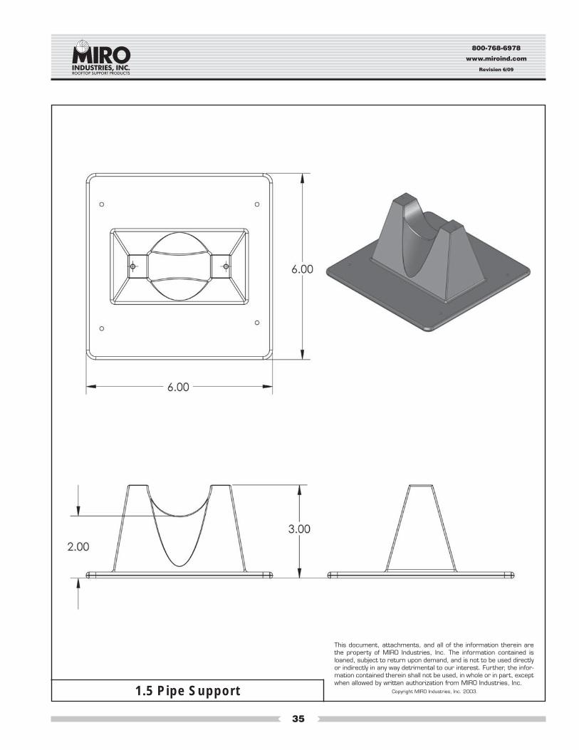
Maximum Pipe Size:1-1/2" Inside diameter1-9/10" Outside diameter
Specification and Data Sheet
MODEL NO. 1.51. Product Name: PILLOW BLOCK PIPESTAND MODEL NO. 1.5 NOTE: Pillowblock pipestand model numbers correspond to
usual pipe names. Pipe that is called “inch and one-half” or 1-1/2" pipe has a 1.5" inside diameter and a larger outside diameter.Model 1.5 will hold all usual and customary 1-1/2" and smaller pipe sizes, referring to the inside diameter. The maximum outsidedimension of the pipe or conduit the model 1.5 will hold is 1.90" diameter.
2. Manufacturer: MIRO INDUSTRIES, INC., 2700 South 900 West, Salt Lake City, Utah 84119 Phone (800) 768-6978Fax (800) 440-7958
3. Product Description: A pipe support used to support roof mounted gas pipes, electrical conduit, solar piping and other me-chanical piping. Unique design absorbs thermal expansion and contraction of pipes thus preventing damage to the roof mem-brane. Pipes rest in a “U” shaped cradle situated in a polycarbonate resin seat. Each pipe stand will accommodate up to 1.5"inside diameter pipes. The maximum outside diameter of pipe which can be cradled in the Model 1.5 support is 1.9 inches.
4. Product Performance: The design of the cradle serves to keep the pipestand system directly beneath the pipe without binding.Guide holes are provided at the top of the cradle for any desired loose installation of a MIRO Pipe Strap using 1/2" #8 screws toprevent separation of the pipe from the support. The base is gently rounded to prevent gouging the roof membrane.
5. Compatibility: Pillow Block Pipestands are recommended and are compatible for use with all current types of decking and withall commonly used builtup and single-ply roofing membranes where roof-mounted pipes occur.
6. Load Weight: Maximum load weight may not exceed 80 lbs. per pipestand.
7. Composition and Materials: A one-piece roof deck base and “U” shaped housing. The pipestand is composed of rigid polycar-bonate resin with carbon black added for UV resistance and protection.
8. Size: The Pillow Block Pipestand Model 1.5 is made in one standard size. The deck base is 6" square, the top of the “U” cradleis 3" high, and the maximum inside width of the cradle is 1.95". Pipes supported one pipestand high will have a clearance of 2"from bottom of pipe support. Model 1.5 Spacer can be stacked 2 or 3 high, to give greater height to pipe or conduit. Each stackinglayer increases the clearance by 1.5".
9. Installation: To install the pillow block pipestands, (1) center the pipestand beneath the pipe so that the cradle allows the pipe tobe squarely over and through the cradle of the pipestand. (2) Set the pipe in the pipestand without dropping or causing undueimpact. If desired, an additional sheet of roofing material, a MIRO Support Pad, or a MIRO Deck Plate can be installed beneaththe pipestand. For builtup roofs, all loose aggregate from an area 10" square should be removed from the area directly beneaththe pipestand and then follow the installation directions set forth above. Care should be taken to install each pipestand so itsupports a proportional and equal amount of weight with all other pipestands.
OPTIONAL METHOD OF INSTALLATION (Not recommended): Where code requires or as desired, the pipestands may beattached to the roof by appropriate and compatible rooftop fasteners through holes then drilled in the bottom of the pipestandpitchpan.
In addition, the pipe may be secured to the pipestand by using a MIRO Pipe Strap and #8 stainless steel screws in the guideholes at the top of each pipestand. Note: allow sufficient room between the pipe and the strap to provide for free movement of thepipe without binding.
10. Spacing: Manufacturer’s recommended spacing is not to exceed 10 feet centers depending upon the load. Make certain eachpipestand is properly elevated to even load weight at all pipestands.
11. Availability: Pillow Block Pipestands are marketed throughout the United States through representatives and distributors.
12. Maintenance: Normally maintenance is not required. Semi-annual inspection is required to check pipestand position and setpipe alignment, weight distribution, and improper installation which may cause pipestand damage or failure.
13. Technical Services: Please call MIRO INDUSTRIES, INC.: (800) 768-6978 or visit our website www.miroind.com for technicalinformation and for graphic and CAD drawing downloads.
800-768-6978
www.miroind.com
Revision 6/09
35
This document, attachments, and all of the information therein arethe property of MIRO Industries, Inc. The information contained isloaned, subject to return upon demand, and is not to be used directlyor indirectly in any way detrimental to our interest. Further, the infor-mation contained therein shall not be used, in whole or in part, exceptwhen allowed by written authorization from MIRO Industries, Inc.
Copyright MIRO Industries, Inc. 2003.1.5 Pipe Support
800-768-6978
www.miroind.com
Revision 6/09
36
Maximum Pipe Size:3" Inside diameter3-3/4" Outside diameter
Specification and Data Sheet
MODEL NO. 3-R-2 and 3-R-41. Product Name: PILLOW BLOCK PIPESTAND MODEL NO. 3-R NOTE: Pillowblock pipestand model numbers correspond to
usual pipe names. Pipe that is called “three inch” or 3" pipe has a 3" inside diameter and a larger outside diameter. Model 3-R-2 and3-R-4 will hold all usual and customary 3" and smaller pipe sizes, referring to the inside diameter. The maximum outsidedimension of the pipe or conduit the Model 3-R-2 and 3-R-4 will hold is 3-3/4" diameter.
2. Manufacturer: MIRO INDUSTRIES, INC., 2700 South 900 West, Salt Lake City, Utah 84119 Phone (800) 768-6978Fax (800) 440-7958
3. Product Description: A “roller-bearing” pipe support used to support roof mounted gas pipes, electrical conduit, solar pipingand other mechanical piping. Unique design absorbs thermal expansion and contraction of pipes thus preventing damage to theroof membrane. Pipes rest on a polycarbonate resin roller and a polycarbonate rod situated in a polycarbonate resin seat. Eachpipestand will accommodate up to 3-3/4" outside diameter pipes.
4. Product Performance: The “U” shaped roller serves to keep the pipestand roller system directly beneath the pipe withoutbinding. It also allows for some lateral expansion of the pipe system. Guide holes are provided at the top of the cradle for anydesired installation of a MIRO Pipe Strap using 1/2" #8 screws to prevent separation of the pipe from the support. The base isgently rounded to prevent gouging the roof membrane and increased elevations may be achieved by stacking the 3-R-2 and3-R-4 on one or two spacers, each with a height of 2".
5. Compatibility: Pillow Block Pipestands are recommended and are compatible for use with all current types of decking and withall commonly used built-up and single-ply roofing membranes where roof-mounted pipes occur.
6. Load Weight: Maximum load weight may not exceed 100 lbs. per pipestand.
7. Composition and Materials: A one-piece roof deck base, a roller housing support composed of rigid polycarbonate resin withcarbon black added for UV resistance and protection, and a roller made of polycarbonate resin which rests on a polycarbonaterod of 9/16" diameter.
8. Size: The Pillow Block Pipestand Model 3-R-2 and 3-R-4 have a deck base of 7.75" square, the top of the cradle is 4" high, andthe maximum width of the interior of the cradle is 3.875". Rod and pipes supported on the 3-R-2 pipestand will have a clearanceof 2.15". Rod and pipes supported on the 3-R-4 pipestand will have a clearance of 4". Each 3-R spacer increases the clearanceof the pipe by 2".
9. Installation: To install the pillow block pipestands, (1) center the pipestand beneath the pipe so that the cradle allows the pipe tobe squarely over and through the cradle of the pipestand. (2) Set the pipe in the pipestand without dropping or causing undueimpact. If desired, an additional sheet of roofing material, a MIRO Support Pad, or a MIRO Deck Plate can be installed beneaththe pipestand. For built-up roofs, all loose aggregate from an area 12" square should be removed from the area directly beneaththe pipestand and then follow the installation directions set forth above.
OPTIONAL METHOD OF INSTALLATION (Not recommended): Where code requires or as desired, the pipestands may beattached to the roof by appropriate and compatible rooftop fasteners through holes provided in the bottom of the pipestandpitchpan.
In addition, the pipe may be secured to the pipestand by using a MIRO Pipe Strap and #8 stainless steel screws in the guideholesat the top of each pipestand. Note: allow sufficient room between the pipe and the strap to provide for free movement of the pipewithout binding.
10. Spacing: Manufacturer’s recommended spacing is not to exceed 10 feet centers depending upon the load. Make certain eachpipestand is properly elevated to even load weight at all pipestands.
11. Availability: Pillow Block Pipestands are marketed throughout the United States through representatives and distributors.
12. Maintenance: Normally maintenance is not required. Semi-annual inspection is required to check pipestand position and setpipe alignment, weight distribution, and improper installation which may cause pipestand damage or failure.
13. Technical Services: Please call MIRO INDUSTRIES, INC.: (800) 768-6978 or visit our website www.miroind.com for technicalinformation and for graphic and CAD drawing downloads.
800-768-6978
www.miroind.com
Revision 6/09
37
This document, attachments, and all of the information therein arethe property of MIRO Industries, Inc. The information contained isloaned, subject to return upon demand, and is not to be used directlyor indirectly in any way detrimental to our interest. Further, the infor-mation contained therein shall not be used, in whole or in part, exceptwhen allowed by written authorization from MIRO Industries, Inc.
Copyright MIRO Industries, Inc. 2003.3-R-2 Pipe Support
800-768-6978
www.miroind.com
Revision 6/09
38
This document, attachments, and all of the information therein arethe property of MIRO Industries, Inc. The information contained isloaned, subject to return upon demand, and is not to be used directlyor indirectly in any way detrimental to our interest. Further, the infor-mation contained therein shall not be used, in whole or in part, exceptwhen allowed by written authorization from MIRO Industries, Inc.
Copyright MIRO Industries, Inc. 2003.3-R-4 Pipe Support
800-768-6978
www.miroind.com
Revision 6/09
39
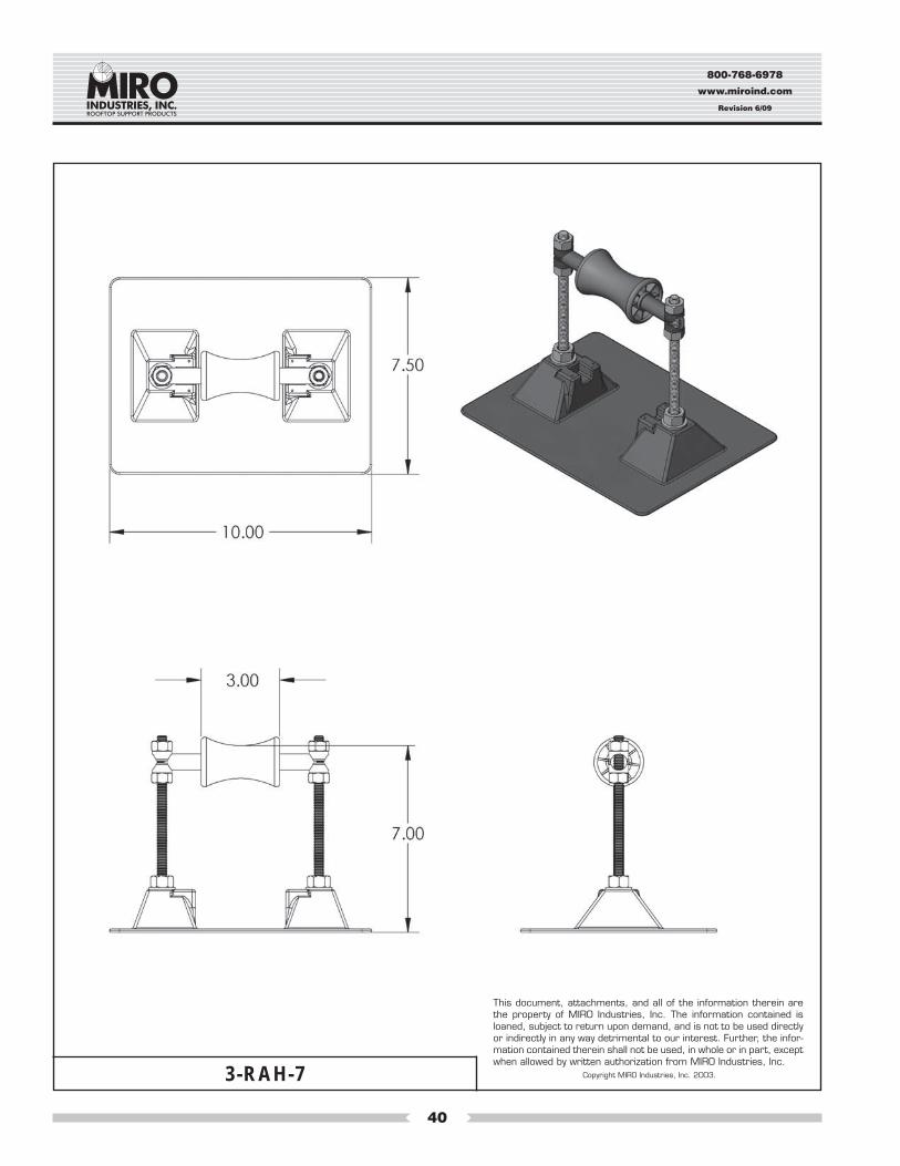
Maximum Pipe Size:3" Inside diameter3.75" Outside diameter
1. Product Name: PILLOW BLOCK PIPESTAND MODEL 3-RAH-7 and 3-RAH-12. NOTE: Pillowblock pipestand modelnumbers correspond to usual pipe names. Pipe that is called “three inch” or 3" pipe has a 3" inside diameter and a largeroutside diameter. Model 3-RAH-7 and 3-RAH-12 will hold up to all usual and customary 3" and smaller pipe sizes, refer-ring to the inside diameter. The maximum outside dimension of the pipe or conduit the Model 3-RAH-7 and 3-RAH-12 willhold is 3.75" diameter.
2. Manufacturer: MIRO INDUSTRIES, INC., 2700 South 900 West, Salt Lake City, Utah 84119 Phone (800) 768-6978Fax (800) 440-7958
3. Product Description: A “roller-bearing” pipe support used to support roof mounted gas pipes, electrical conduit, solarpiping and other mechanical piping. Unique design absorbs thermal expansion and contraction of pipes thus preventingdamage to the roof membrane. Pipes rest on a self-lubricating roller polycarbonate resin rod and roller. The pipe supportbase, roller and rod are made of sturdy polycarbonate resin, and all metal parts are made of stainless steel. Pipestand willaccommodate up to 3" inside diameter pipe or up to 3-7/8" outside diameter pipes.
4. Product Performance: The “U” shaped roller serves to keep the pipestand roller system directly beneath the pipe withoutbinding and allows for some lateral expansion of the piping system. The base is gently rounded to prevent gouging theroof membrane.
5. Compatibility: Pillow Block Pipestands are recommended for use on and are compatible with all current types of deckingwith all commonly used built-up and single-ply roofing membranes where roof-mounted pipes occur.
6. Load Weight: Maximum load weight may not exceed 100 lbs. per pipestand.
7. Composition and Materials: The pipestand consists of two major components: (1) A one-piece polycarbonate resinroof deck base, pipe support, and adjustable roller housing, (2) A roller and rod made of polycarbonate resin connectedwith 3/8" diameter all thread designed for adjustable height. Carbon black is added to the polycarbonate resin for UVresistance and protection.
8. Size: Pillow Block Pipestand Model 3-RAH-7 has a deck base that is 7.50" by 10.00". Model 3-RAH-12 has a deck baseof 9" x 15.25", and has a maximum cradle width of 4". The 3-RAH-7 can adjust in height from a low of 3.5" to a high of 7"from bottom of pipe support. The 3-RAH-12 can adjust in height from a low of 5.5" to a high of 12".
9. Installation: (1) Center the pipestand beneath the pipe so that the cradle allows the pipe to be squarely over and throughthe roller of the pipestand. (2) Adjust the pipestand to the desired height and to even load with other pipestands. Makecertain the strut or roller is level. (3) Set the pipe in the pipestand without dropping or causing undue impact. If desired, anadditional sheet of roofing material, a MIRO Support Pad, or a MIRO Deck Plate can be installed beneath the pipestand.For built-up roofs, all loose aggregate from an area 15" square should be removed from the area directly beneath thepipestand and then follow the installation directions set forth above. Care should be taken to install each pipestand so itsupports a proportional and equal amount of weight at each pipestand.
10. Spacing: Manufacturer’s recommended spacing is not to exceed 10 foot centers depending upon the load. Do not ex-ceed 100 lbs. load weight and make certain each pipestand is adjusted in height to even load.
11. Availability: Pillow Block pipestands are marketed throughout the United States through representatives and distribu-tors.
12. Maintenance: Normally maintenance is not required. Semi-annual inspection is required to check pipestand position andset pipe alignment, weight distribution and improper installation which may cause pipestand damage or failure.
13. Technical Services: Please call MIRO INDUSTRIES, INC.: (800) 768-6978 or visit our website www.miroind.com fortechnical information and for graphic and CAD drawing downloads.
Specification and Data Sheet
MODEL NO. 3-RAH-7 and 3-RAH-12
800-768-6978
www.miroind.com
Revision 6/09
40
3-RAH-7
This document, attachments, and all of the information therein arethe property of MIRO Industries, Inc. The information contained isloaned, subject to return upon demand, and is not to be used directlyor indirectly in any way detrimental to our interest. Further, the infor-mation contained therein shall not be used, in whole or in part, exceptwhen allowed by written authorization from MIRO Industries, Inc.
Copyright MIRO Industries, Inc. 2003.
800-768-6978
www.miroind.com
Revision 6/09
41
3-RAH-12
This document, attachments, and all of the information therein arethe property of MIRO Industries, Inc. The information contained isloaned, subject to return upon demand, and is not to be used directlyor indirectly in any way detrimental to our interest. Further, the infor-mation contained therein shall not be used, in whole or in part, exceptwhen allowed by written authorization from MIRO Industries, Inc.
Copyright MIRO Industries, Inc. 2003.
800-768-6978
www.miroind.com
Revision 6/09
42
Maximum Pipe Size:4" Inside diameter5" Outside diameter
Specification and Data SheetMODEL NO. 4-R, 4-RAH-7 and 4-RAH-12
1. Product Name: PILLOW BLOCK PIPESTAND MODELS 4-R and 4-RAH-7 and 4-RAH-12. NOTE: Pillowblock pipestands model num-bers correspond to usual pipe names. Pipe that is called “four inch” or 4" pipe has a 4" inside diameter and a larger outside diameter.Model 4-R, 4-RAH-7 and 4-RAH-12 will hold all usual and customary 4" and smaller pipe sizes, referring to the inside diameter. Themaximum outside dimension of the pipe or conduit the Model 4-R will hold is 5" diameter.
2. Manufacturer: MIRO INDUSTRIES, INC., 2700 South 900 West, Salt Lake City, Utah 84119 Phone (800) 768-6978Fax (800) 440-7958
3. Product Description: A “roller-bearing” pipe support used to support roof-mounted gas pipes, electrical conduit, solar piping and othermechanical piping. Unique design absorbs thermal expansion and contraction of pipes thus preventing damage to the roof membrane.Pipes rest on a self-lubricating roller system which is made of a polycarbonate resin rod and a sturdy polycarbonate resin roller. The pipesupport base and roller rod are made of polycarbonate resin, and all metal parts are made of stainless steel. Pipestand will accommo-date up to 4" inside diameter pipe or up to 5" outside diameter pipes.
4. Product Performance: As daytime temperatures warm the roof membrane and the mechanical pipe network found on the roof, causingthem to expand, the roller bearing in the pipestand rolls beneath the pipe it supports. This reduces or eliminates the friction that wouldotherwise occur between the pipe and the roof membrane. When the roofing membrane and pipe network cools, the process is re-versed, and the pipes roll back on the roller bearing as they contract. With a difference of 20 degrees F. between nighttime and daytimetemperatures, 100 ft. of 1" steel pipe may move as much as .25 inches per day. The “U” shaped roller serves to keep the pipestand rollersystem directly beneath the pipe without binding and allows for some lateral expansion of the piping system. The base is gently roundedto prevent gouging the roof membrane.
5. Compatibility: Pillow Block Pipestands are recommended for use on and are compatible with all current types of decking and with allcommonly used built-up and single-ply roofing membranes where roof-mounted pipes occur.
6. Load Weight: Maximum load weight may not exceed 125 lbs. per pipestand.
7. Composition and Materials: The pipestand consists of two major components: (1) A one-piece polycarbonate roof deck base, pipesupport, and adjustable roller housing, (2) A roller and rod made of polycarbonate resin rod which rests in a fixed saddle on the 4-R oran adjustable height roller housing connected with 3/8" diameter all thread on the 4-RAH-7 or 4-RAH-12. Carbon black is added to thepolycarbonate for UV resistance and protection.
8. Size: Pillow Block Pipestand Models 4-R and 4-RAH-7 are made with a deck base that is 7.50" by 10.00". The 4-RAH-12 has a deckbase of 9" by 15.25" and has a maximum cradle width of 5".
4-R has a maximum pipe clearance of 2.15".4-RAH-7 can adjust in height from a low of 3.5" to a high of 7.5" from bottom of pipe support.4-RAH-12 can adjust in height from a low of 5.5" to a high of 12.0" from bottom of pipe support.
9. Installation: (1) Center the pipestand beneath the pipe so that the cradle allows the pipe to be squarely over and through the roller of thepipestand. (2) Adjust the pipestand to the desired height and even load with other pipestands. Make certain the strut or roller is level. (3)Set the pipe in the pipestand without dropping or causing undue impact. If desired, an additional sheet of roofing material, a MIROSupport Pad, or a MIRO Deck Plate can be installed beneath the pipestand. For built-up roofs, all loose aggregate from an area 15"square should be removed from the area directly beneath the pipestand and then follow the installation directions set forth above. Careshould be taken to install each pipestand so it supports a proportional and equal amount of weight at each pipestand.
OPTIONAL METHOD OF INSTALLATION (Not recommended): Where code requires or as desired, the pipestands may be attached tothe roof by appropriate and compatible rooftop fasteners through holes then drilled in the bottom of the pipestand pitchpan at the time ofinstallation.
10. Spacing: Manufacturer’s recommended spacing is not to exceed 10 foot centers depending upon the load. Do not exceed 125 lbs. loadweight and make certain each pipestand is adjusted in height to even load.
11. Availability: Pillow Block Pipestands are marketed throughout the United States through representatives and distributors.
12. Maintenance: Normally maintenance is not required. Semi-annual inspection is required to check pipestand position and set pipealignment, weight distribution and improper installation which may cause pipestand damage or failure.
13. Technical Services: Please call MIRO INDUSTRIES, INC.: (800) 768-6978 or visit our website www.miroind.com for technical informa-tion and for graphic and CAD drawing downloads.
800-768-6978
www.miroind.com
Revision 6/09
43
4-R Pipe Support
This document, attachments, and all of the information therein arethe property of MIRO Industries, Inc. The information contained isloaned, subject to return upon demand, and is not to be used directlyor indirectly in any way detrimental to our interest. Further, the infor-mation contained therein shall not be used, in whole or in part, exceptwhen allowed by written authorization from MIRO Industries, Inc.
Copyright MIRO Industries, Inc. 2003.
800-768-6978
www.miroind.com
Revision 6/09
44
4-RAH-7
This document, attachments, and all of the information therein arethe property of MIRO Industries, Inc. The information contained isloaned, subject to return upon demand, and is not to be used directlyor indirectly in any way detrimental to our interest. Further, the infor-mation contained therein shall not be used, in whole or in part, exceptwhen allowed by written authorization from MIRO Industries, Inc.
Copyright MIRO Industries, Inc. 2003.
800-768-6978
www.miroind.com
Revision 6/09
45
4-RAH-12
This document, attachments, and all of the information therein arethe property of MIRO Industries, Inc. The information contained isloaned, subject to return upon demand, and is not to be used directlyor indirectly in any way detrimental to our interest. Further, the infor-mation contained therein shall not be used, in whole or in part, exceptwhen allowed by written authorization from MIRO Industries, Inc.
Copyright MIRO Industries, Inc. 2003.
800-768-6978
www.miroind.com
Revision 6/09
46
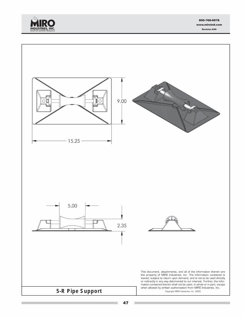
Specification and Data SheetMODEL NO. 5-R, 5-RAH-7 and 5-RAH-12
Maximum Pipe Size:5" Inside diameter6" Outside diameter
1. Product Name: PILLOW BLOCK PIPESTAND MODELS 5-R and 5-RAH-7 and 5-RAH-12. NOTE: Pillowblock pipestands are givenmodel numbers which correspond to usual pipe names. Pipe that is called “five inch” or 5" pipe has a 5" inside diameter and a largeroutside diameter. All usual and customary 5" and smaller pipe sizes, referring to the inside diameter. The maximum outside dimensionof the pipe or conduit the Models 5-R, 5-RAH-7, and 5-RAH-12 will hold is 6" diameter.
2. Manufacturer: MIRO INDUSTRIES, INC., 2700 South 900 West, Salt Lake City, Utah 84119 Phone (800) 768-6978Fax (800) 440-7958
3. Product Description: A “roller-bearing” pipe support used to support roof-mounted gas pipes, electrical conduit, solar piping and othermechanical piping. Unique design absorbs thermal expansion and contraction of pipes thus preventing damage to the roof membrane.Pipes rest on a self-lubricating roller which is made of a stainless steel rod and a sturdy polycarbonate resin roller. The pipe support baseis made of polycarbonate plastic and all metal parts are made of stainless steel. Pipestand will accommodate up to 5" inside diameterpipe and up to 6" outside diameter pipes.
4. Product Performance: As daytime temperatures warm the roof membrane and the mechanical pipe network found on the roof, causingthem to expand, the roller bearing in the pipestand rolls beneath the pipe it supports. This reduces or eliminates the friction that wouldotherwise occur between the pipe and the roof membrane. When the roofing membrane and pipe network cools, the process is re-versed, and the pipes roll back on the roller bearing as they contract. With a difference of 20 degrees F. between nighttime and daytimetemperatures, 100 ft. of 1" steel pipe may move as much as .25 inches per day. The “U” shaped roller serves to keep the pipestand rollersystem directly beneath the pipe without binding and allows for some lateral expansion of the piping system. The base is gently roundedto prevent gouging the roof membrane.
5. Compatibility: Pillow Block Pipestands are recommended for use on and compatible with all current types of decking and with allcommonly used built-up and single-ply roofing membranes where roof-mounted pipes occur.
6. Load Weight: Maximum load weight may not exceed 150 lbs. per pipestand.
7. Composition and Materials: The pipestand consists of two major components: (1) A one-piece polycarbonate resin roof deck base, pipesupport, adjustable roller housing, and (2) A stainless steel rod and polycarbonate resin roller which rest in a fixed saddle on the 5-R or anadjustable height roller housing connected with 1/2" diameter all thread on the 5-RAH-7 or 5-RAH-12. Carbon black is added to thepolycarbonate resin for UV resistance and protection.
8. Size: Pillow Block Pipestand Models 5-R, 5-RAH-7 and 5-RAH-12 are made in one standard size. The deck base is 9" by 15.25" and hasa maximum cradle width of 9", but is designed to hold a maximum of 5" inside or a maximum of 6" outside diameter pipe.
5-R has a maximum pipe clearance of 2.35". 5-RAH-7 can adjust in height from a low of 3.5" to a high of 7" from bottom of pipe support. 5-RAH-12 can adjust in height from a low of 3.5" to a high of 12" from bottom of pipe support.
9. Installation: (1) Center the pipestand beneath the pipe so that the cradle allows the pipe to be squarely over and through the roller of thepipestand. (2) Adjust the pipestand to the desired height and even load with other pipestands. Make certain the roller or strut is level. (3)Set the pipe in the pipestand without dropping or causing undue impact. If desired, an additional sheet of roofing material, a MIROSupport Pad, or a MIRO Deck Plate can be installed beneath the pipestand. For built-up roofs, all loose aggregate from an area 20"square should be removed from the area directly beneath the pipestand and then follow the installation directions set forth above. Careshould be taken to install each pipestand so it supports a proportional and equal amount of weight with all other pipestands.
OPTIONAL METHOD OF INSTALLATION (Not recommended): Where code requires or as desired, the pipestands may be attached tothe roof by appropriate and compatible rooftop fasteners through holes then drilled in the bottom of the pipestand pitchpan at the time ofinstallation.
10. Spacing: Manufacturer’s recommended spacing is not to exceed 10 foot centers depending upon the load. Do not exceed 150 lbs. loadweight and make certain each pipestand is adjusted to even load with all other pipestands.
11. Availability: Pillow Block Pipestands are marketed throughout the United States through representatives and distributors.
12. Maintenance: Normally maintenance is not required. Semi-annual inspection is required to check pipestand position and set pipealignment, weight distribution and improper installation which may cause pipestand damage or failure.
13. Technical Services: Please call MIRO INDUSTRIES, INC.: (800) 768-6978 or visit our website www.miroind.com for technical informa-tion and for graphic and CAD drawing downloads.
800-768-6978
www.miroind.com
Revision 6/09
47
5-R Pipe Support
This document, attachments, and all of the information therein arethe property of MIRO Industries, Inc. The information contained isloaned, subject to return upon demand, and is not to be used directlyor indirectly in any way detrimental to our interest. Further, the infor-mation contained therein shall not be used, in whole or in part, exceptwhen allowed by written authorization from MIRO Industries, Inc.
Copyright MIRO Industries, Inc. 2003.
800-768-6978
www.miroind.com
Revision 6/09
48
5-RAH-7
This document, attachments, and all of the information therein arethe property of MIRO Industries, Inc. The information contained isloaned, subject to return upon demand, and is not to be used directlyor indirectly in any way detrimental to our interest. Further, the infor-mation contained therein shall not be used, in whole or in part, exceptwhen allowed by written authorization from MIRO Industries, Inc.
Copyright MIRO Industries, Inc. 2003.
800-768-6978
www.miroind.com
Revision 6/09
49
5-RAH-12
This document, attachments, and all of the information therein arethe property of MIRO Industries, Inc. The information contained isloaned, subject to return upon demand, and is not to be used directlyor indirectly in any way detrimental to our interest. Further, the infor-mation contained therein shall not be used, in whole or in part, exceptwhen allowed by written authorization from MIRO Industries, Inc.
Copyright MIRO Industries, Inc. 2003.
800-768-6978
www.miroind.com
Revision 6/09
50
Maximum Pipe Size:6" Inside diameter8.5" Outside diameter
1. Product Name: PILLOW BLOCK PIPESTAND MODEL 6-RAH-7 AND 6-RAH-12 NOTE: Pillowblock pipestand modelnumbers correspond to usual pipe names. Pipe that is called “six inch” or 6" pipe has a 6" inside diameter and a largeroutside diameter. Model 6-RAH-7 and 6-RAH-12 will hold up to all usual and customary 6" and smaller pipe sizes, refer-ring to the inside diameter. The maximum outside dimension of the pipe or conduit the Model 6-RAH-7 and 6-RAH-12 willhold is 8.5" diameter.
2. Manufacturer: MIRO INDUSTRIES, INC., 2700 South 900 West, Salt Lake City, Utah 84119 Phone (800) 768-6978Fax (800) 440-7958
3. Product Description: A “roller-bearing” pipe support used to support roof mounted gas pipes, electrical conduit, solarpiping and other mechanical piping. Unique design absorbs thermal expansion and contraction of pipes thus preventingdamage to the roof membrane. Pipes rest on a self-lubricating roller which is a 304 stainless steel rod and a polycarbon-ate resin roller. The pipe support base is made of sturdy polycarbonate resin, the roller is polycarbonate and all metal partsare made of stainless steel. Pipestand will accommodate up to 6" inside diameter pipe or up to 8.5" outside diameterpipes.
4. Product Performance: The “U” shaped roller serves to keep the pipestand roller system directly beneath the pipe withoutbinding and allows for some lateral expansion of the piping system. The base is gently rounded to prevent gouging.
5. Compatibility: Pillow Block Pipestands are recommended for use on and are compatible with all current types of deckingwith all commonly used built-up and single-ply roofing membranes where roof-mounted pipes occur.
6. Load Weight: Maximum load weight may not exceed 250 lbs. per pipestand.
7. Composition and Materials: The pipestand consists of two major components: (1) A one-piece polycarbonate resin roofdeck base, pipe support, and adjustable roller housing, (2) A roller made of polycarbonate resin and a stainless steel rodwhich rests in an adjustable height roller housing connected with 1/2" diameter all thread on the 6-RAH. Carbon black isadded to the polycarbonate resin for UV resistance and protection.
8. Size: Pillow Block Pipestand Model 6-RAH-7 and 6-RAH-12 is made in one standard size. The deck is 16" x 18" and hasa maximum cradle width of 8.5". The 6-RAH-7 can adjust in height from a low of 4.5" to a high of 7.5" from bottom of pipesupport. The 6-RAH-12 can adjust in height from a low of 4.5" to a high of 12".
9. Installation: (1) Center the pipestand beneath the pipe so that the cradle allows the pipe to be squarely over and throughthe roller of the pipestand. (2) Adjust the pipestand to the desired height and to even load with other pipestands. Makecertain the strut or roller is level. (3) Set the pipe in the pipestand without dropping or causing undue impact. If desired, anadditional sheet of roofing material, a MIRO Support Pad, or a MIRO Deck Plate can be installed beneath the pipestand.For built-up roofs, all loose aggregate from an area 20" square should be removed from the area directly beneath thepipestand and then follow the installation directions set forth above. Care should be taken to install each pipestand so itsupports a proportional and equal amount of weight at each pipestand.
10. Spacing: Manufacturer’s recommended spacing is not to exceed 10 foot centers depending upon the load. Do not ex-ceed 250 lbs. load weight and make certain each pipestand is adjusted in height to even load.
11. Availability: Pillow Block pipestands are marketed throughout the United States through representatives and distribu-tors.
12. Maintenance: Normally maintenance is not required. Semi-annual inspection is required to check pipestand position andset pipe alignment, weight distribution and improper installation which may cause pipestand damage or failure.
13. Technical Services: Please call MIRO INDUSTRIES, INC.: (800) 768-6978 or visit our website www.miroind.com fortechnical information and for graphic and CAD drawing downloads.
Specification and Data Sheet
MODEL NO. 6-RAH-7 and 6-RAH-12
800-768-6978
www.miroind.com
Revision 6/09
51
6-RAH-7
This document, attachments, and all of the information therein arethe property of MIRO Industries, Inc. The information contained isloaned, subject to return upon demand, and is not to be used directlyor indirectly in any way detrimental to our interest. Further, the infor-mation contained therein shall not be used, in whole or in part, exceptwhen allowed by written authorization from MIRO Industries, Inc.
Copyright MIRO Industries, Inc. 2003.
800-768-6978
www.miroind.com
Revision 6/09
52
6-RAH-12
This document, attachments, and all of the information therein arethe property of MIRO Industries, Inc. The information contained isloaned, subject to return upon demand, and is not to be used directlyor indirectly in any way detrimental to our interest. Further, the infor-mation contained therein shall not be used, in whole or in part, exceptwhen allowed by written authorization from MIRO Industries, Inc.
Copyright MIRO Industries, Inc. 2003.
800-768-6978
www.miroind.com
Revision 6/09
53
Specification and Data SheetMODEL NO. 3-RAH-7 (SS or HDG)
Maximum Pipe Size:3" Inside diameter3.75" Outside diameter
1. Product Name: PILLOW BLOCK PIPESTAND MODEL NO. 3-RAH-7 (SS or HDG). NOTE: Pillowblock pipestands are givenmodel numbers which correspond to usual pipe names. Pipe that is called “three inch” or 3" pipe has a 3" inside diameter and alarger outside diameter. Model 3-RAH-7 (SS or HDG) will hold all usual and customary 3" and smaller pipe sizes, referring to theinside diameter. The maximum outside dimension of the pipe or conduit the Model 3-RAH-7 (SS or HDG) will hold is 3.75" diameter.
2. Manufacturer: MIRO INDUSTRIES, INC., 2700 South 900 West, Salt Lake City, Utah 84119 Phone (800) 768-6978Fax (800) 440-7958
3. Product Description: A “roller-bearing” pipe support used to support roof-mounted gas pipes, electrical conduit, solar piping andother mechanical piping. Unique design absorbs thermal expansion and contraction of pipes thus preventing damage to the roofmembrane. Pipes rest on a self-lubricating roller which is made of a stainless steel rod and a polycarbonate resin roller. The pipesupport base is made of stainless steel or hot-dip galvanized steel and all other metal parts are made of stainless steel. Pipestandwill accommodate up to 3" inside diameter pipe or up to 3.75" outside diameter pipes.
4. Product Performance: The “U” shaped cradle serves to keep the pipestand roller system directly beneath the pipe withoutbinding and allows for some lateral expansion of the piping system. The base is gently rounded to prevent gouging with edgesraised 1". Drainage ports are provided to prevent ponding within the device.
5. Compatibility: Pillow Block Pipestands are recommended for use and are compatible with all current types of decking and withall commonly used built-up and single-ply roofing membranes where roof-mounted pipes occur.
6. Load Weight: Maximum load weight may not exceed 100 lbs. per pipestand.
7. Composition and Materials: The pipestand consists of two major components: (1) A one-piece stainless or hot-dip galvanizedsteel roof deck base, pipe support, and adjustable roller housing, and (2) A roller made of polycarbonate resin and a stainlesssteel rod which rests upon the adjustable height roller housing connected with 3/8" diameter all thread. Carbon black is added tothe polycarbonate resin for UV resistance and protection.
8. Size: Pillow Block Pipestand Models 3-RAH-7 (SS or HDG) is made in one standard size. The deck base is 8" by 14", has amaximum cradle width of 4", and can adjust in height from a low of 3.5" to a high of 7" from bottom of pipe support.
9. Installation: (1) Center the pipestand beneath the pipe so that the cradle allows the pipe to be squarely over and through theroller of the pipestand. (2) Adjust the pipestand to the desired height and even load with other pipestands. Make certain the rollerand horizontal rod is level. (3) Set the pipe in the pipestand without dropping or causing undue impact. If desired, an additionalsheet of roofing material, a MIRO Support Pad, or a MIRO Deck Plate can be installed beneath the pipestand. For built-up roofs,all loose aggregate from an area 15" square should be removed from the area directly beneath the pipestand and then follow theinstallation directions set forth above. Care should be taken to install each pipestand so it supports a proportional and equalamount of weight at each pipestand.
OPTIONAL METHOD OF INSTALLATION (Not recommended): Where code requires or as desired, the pipestands may beattached to the roof by appropriate and compatible rooftop fasteners through holes then drilled in the bottom of the pipestandpitchpan at the time of installation.
10. Spacing: Manufacturer’s recommended spacing should not exceed 10 foot centers depending upon the load. Do not exceed100 lbs. load weight and make certain each pipestand is adjusted in height to even load with all other pipestands.
11. Availability: Pillow Block Pipestands are marketed throughout the United States through representatives and distributors.
12. Maintenance: Normally maintenance is not required. Semi-annual inspection is required to check pipestand position and setpipe alignment, weight distribution and improper installation which may cause pipestand damage or failure.
13. Technical Services: Please call MIRO INDUSTRIES, INC.: (800) 768-6978 or visit our website www.miroind.com for technicalinformation and for graphic and CAD drawing downloads.
800-768-6978
www.miroind.com
Revision 6/09
54
3-RAH-7 SS
This document, attachments, and all of the information therein arethe property of MIRO Industries, Inc. The information contained isloaned, subject to return upon demand, and is not to be used directlyor indirectly in any way detrimental to our interest. Further, the infor-mation contained therein shall not be used, in whole or in part, exceptwhen allowed by written authorization from MIRO Industries, Inc.
Copyright MIRO Industries, Inc. 2003.
800-768-6978
www.miroind.com
Revision 6/09
55
3-RAH-7 HDG
This document, attachments, and all of the information therein arethe property of MIRO Industries, Inc. The information contained isloaned, subject to return upon demand, and is not to be used directlyor indirectly in any way detrimental to our interest. Further, the infor-mation contained therein shall not be used, in whole or in part, exceptwhen allowed by written authorization from MIRO Industries, Inc.
Copyright MIRO Industries, Inc. 2003.
800-768-6978
www.miroind.com
Revision 6/09
56
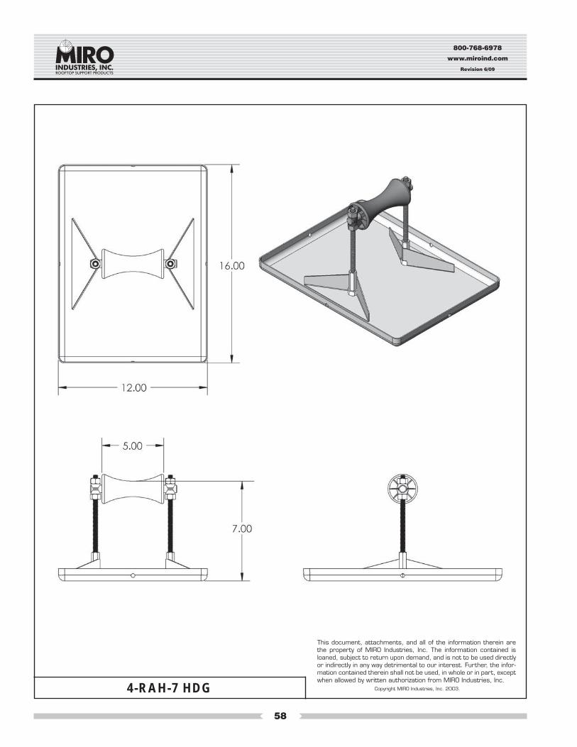
Specification and Data SheetMODEL NO. 4-RAH-7 (SS or HDG)
Maximum Pipe Size:4" Inside diameter5" Outside diameter
1. Product Name: PILLOW BLOCK PIPESTAND MODEL NO. 4-RAH-7 (SS or HDG) NOTE: Pillowblock pipestands are givenmodel numbers which correspond to usual pipe names. Pipe that is called “four inch” or 4" pipe has a 4" inside diameter and alarger outside diameter. Model 4-RAH-7 (SS or HDG) will hold all usual and customary 4" and smaller pipe sizes, referring to theinside diameter. The maximum outside dimension of the pipe or conduit the Model 4-RAH-7 (SS or HDG) will hold is 5" diameter.
2. Manufacturer: MIRO INDUSTRIES, INC., 2700 South 900 West, Salt Lake City, Utah 84119 Phone (800) 768-6978Fax (800) 440-7958
3. Product Description: A “roller-bearing” pipe support used to support roof-mounted gas pipes, electrical conduit, solar piping andother mechanical piping. Unique design absorbs thermal expansion and contraction of pipes thus preventing damage to the roofmembrane. Pipes rest on a self-lubricating roller which is made of a stainless steel rod and a polycarbonate resin roller. The pipesupport base is made of stainless steel or hot-dip galvanized steel and all other metal parts are made of stainless steel. Pipestandwill accommodate up to 4" inside diameter pipe or up to 5" outside diameter pipes.
4. Product Performance: The “U” shaped cradle serves to keep the pipestand roller system directly beneath the pipe withoutbinding and allows for some lateral expansion of the piping system. The base is gently rounded to prevent gouging with edgesraised 1". Drainage ports are provided to prevent ponding within the device.
5. Compatibility: Pillow Block Pipestands are recommended for use and are compatible with all current types of decking and withall commonly used built-up and single-ply roofing membranes where roof-mounted pipes occur.
6. Load Weight: Maximum load weight may not exceed 150 lbs. per pipestand.
7. Composition and Materials: The pipestand consists of two major components: (1) A one-piece stainless or hot-dip galvanizedsteel roof deck base, pipe support, and adjustable roller housing, and (2) A roller made of polycarbonate resin and a stainlesssteel rod which rests upon the adjustable height roller housing connected with 3/8" diameter all thread. Carbon black is added tothe polycarbonate resin for UV resistance and protection.
8. Size: Pillow Block Pipestand Models 4-RAH-7 (SS or HDG) is made in one standard size. The deck base is 12" by 16", has amaximum cradle width of 5.5", and can adjust in height from a low of 3.5" to a high of 7" from bottom of pipe support.
9. Installation: (1) Center the pipestand beneath the pipe so that the cradle allows the pipe to be squarely over and through theroller of the pipestand. (2) Adjust the pipestand to the desired height and even load with other pipestands. Make certain the rollerand horizontal rod is level. (3) Set the pipe in the pipestand without dropping or causing undue impact. If desired, an additionalsheet of roofing material, a MIRO Support Pad, or a MIRO Deck Plate can be installed beneath the pipestand. For built-up roofs,all loose aggregate from an area 20" square should be removed from the area directly beneath the pipestand and then follow theinstallation directions set forth above. Care should be taken to install each pipestand so it supports a proportional and equalamount of weight at each pipestand.
OPTIONAL METHOD OF INSTALLATION (Not recommended): Where code requires or as desired, the pipestands may beattached to the roof by appropriate and compatible rooftop fasteners through holes then drilled in the bottom of the pipestandpitchpan at the time of installation.
10. Spacing: Manufacturer’s recommended spacing should not exceed 10 foot centers depending upon the load. Do not exceed150 lbs. load weight and make certain each pipestand is adjusted in height to even load with all other pipestands.
11. Availability: Pillow Block Pipestands are marketed throughout the United States through representatives and distributors.
12. Maintenance: Normally maintenance is not required. Semi-annual inspection is required to check pipestand position and setpipe alignment, weight distribution and improper installation which may cause pipestand damage or failure.
13. Technical Services: Please call MIRO INDUSTRIES, INC.: (800) 768-6978 or visit our website www.miroind.com for technicalinformation and for graphic and CAD drawing downloads.
800-768-6978
www.miroind.com
Revision 6/09
57
4-RAH-7 SS
This document, attachments, and all of the information therein arethe property of MIRO Industries, Inc. The information contained isloaned, subject to return upon demand, and is not to be used directlyor indirectly in any way detrimental to our interest. Further, the infor-mation contained therein shall not be used, in whole or in part, exceptwhen allowed by written authorization from MIRO Industries, Inc.
Copyright MIRO Industries, Inc. 2003.
800-768-6978
www.miroind.com
Revision 6/09
58
4-RAH-7 HDG
This document, attachments, and all of the information therein arethe property of MIRO Industries, Inc. The information contained isloaned, subject to return upon demand, and is not to be used directlyor indirectly in any way detrimental to our interest. Further, the infor-mation contained therein shall not be used, in whole or in part, exceptwhen allowed by written authorization from MIRO Industries, Inc.
Copyright MIRO Industries, Inc. 2003.
800-768-6978
www.miroind.com
Revision 6/09
59
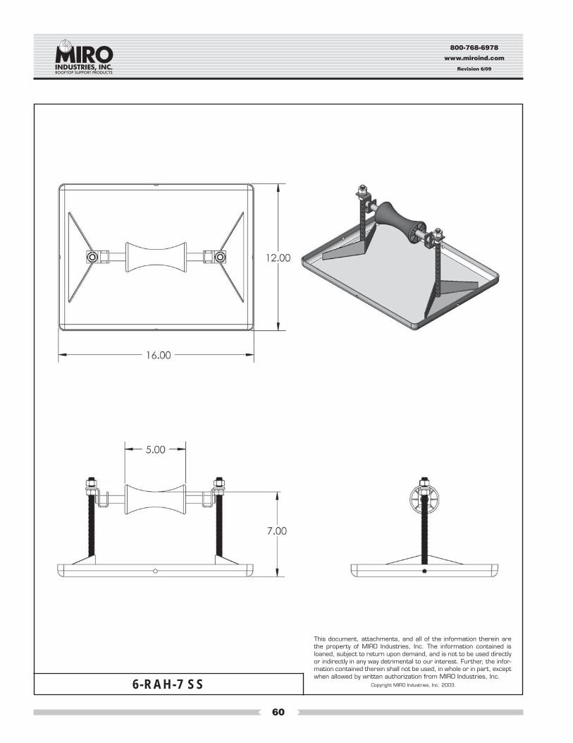
Maximum Pipe Size:6" Inside diameter8-1/2" Outside diameter
Specification and Data SheetMODEL NO. 6-RAH-7 (SS or HDG)
1. Product Name: PILLOW BLOCK PIPESTAND MODEL NO. 6-RAH-7 (SS or HDG). NOTE: Pillowblock pipestands are givenmodel numbers which correspond to usual pipe names. Pipe that is called “six-inch” or 6" pipe has a 6” inside diameter and a largeroutside diameter. Model 6-RAH-7 (SS or HDG). will hold all usual and customary 6" and smaller pipe sizes, referring to the insidediameter. The maximum outside dimension of the pipe or conduit the model 6-RAH-7 (SS or HDG) will hold is 8-1/2" diameter.
2. Manufacturer: MIRO INDUSTRIES, INC., 2700 South 900 West, Salt Lake City, Utah 84119 Phone (800) 768-6978Fax (800) 440-7958
3. Product Description: A “roller-bearing” pipe support used to support roof mounted gas pipes, electrical conduit, solar pipingand other mechanical piping. Unique design absorbs thermal expansion and contraction of pipes thus preventing damage tothe roof membrane. Pipes rest on a self-lubricating roller which is made of a stainless steel rod and a polycarbonate resinroller. The pipe support base is made of stainless steel or hot-dip galvanized steel and all other metal parts are made ofstainless steel. Pipestand will accommodate up to a 6" inside diameter pipe or up to 8-1/2" outside diameter pipes.
4. Product Performance: The “U” shaped cradle serves to keep the pipestand roller system directly beneath the pipe withoutbinding and allows for some lateral expansion of the piping system. The base is gently rounded to prevent gouging with edgesraised 1". Drainage ports are provided to prevent ponding within the device.
5. Compatibility: Pillow Block Pipestands are recommended for use on and compatible with all current types of decking andwith all commonly used built-up and single-ply roofing membranes where roof-mounted pipes occur.
6. Load Weight: Maximum load weight not to exceed 150 lbs. per pipestand.
7. Composition and Materials: The pipestand consists of two major components: (1) A one-piece stainless or hot-dip galva-nized steel roof deck base, pipe support and adjustable roller housing, and (2) A rod made of stainless steel and polycarbon-ate roller which rests upon the adjustable height roller housing connected with 1/2" diameter all thread. Carbon black is addedto the polycarbonate resin for UV resistance and protection.
8. Size: The Pillow Block Pipe Stand Model 6-RAH-7 (SS or HDG) is made in one standard size. The deck base is 12" x 16", has amaximum cradle width of 8-1/2", and can adjust in height from a low of 3.5" to a high of 7" from bottom of pipe support.
9. Installation: (1) Center the pipestand beneath the pipe so that the cradle allows the pipe to be squarely over and through theroller of the pipestand. (2) Adjust the pipestand to the desired height and even load with other pipestands. Make certain theroller and horizontal rod is level. (3) Set the pipe in the pipestand without dropping or causing undue impact. If desired, anadditional sheet of roofing material, a MIRO Support Pad, or a MIRO Deck Plate can be installed beneath the pipestand. Forbuilt up roofs, all loose aggregate from an area 20" square should be removed from the area directly beneath the pipestandand then follow the installation directions set forth above. Care should be taken to install each pipestand so it supports aproportional and equal amount of weight at each pipestand.
OPTIONAL METHOD OF INSTALLATION (Not Recommended): Where code requires or as desired, the pipestands may beattached to the roof by appropriate and compatible rooftop fasteners through holes then drilled in the bottom of the pipestandpitchpan at the time of installation.
10. Spacing: Manufacturer’s recommended spacing is not to exceed 10 foot centers depending upon the load. Do not exceed150 lbs. load weight and make certain each pipestand is adjusted in height to even load at all pipestands.
11. Availability: Pillow Block Pipestands are marketed throughout the United States through representatives and distributors.
12. Maintenance: Normally maintenance is not required. Semi-annual inspection is required to check pipestand position and setpipe alignment, weight distribution and improper installation which may cause pipestand damage or failure.
13. Technical Services: Please call MIRO INDUSTRIES, INC.: (800) 768-6978 or visit our website www.miroind.com for techni-cal information and for graphic and CAD drawing downloads.
800-768-6978
www.miroind.com
Revision 6/09
60
6-RAH-7 SS
This document, attachments, and all of the information therein arethe property of MIRO Industries, Inc. The information contained isloaned, subject to return upon demand, and is not to be used directlyor indirectly in any way detrimental to our interest. Further, the infor-mation contained therein shall not be used, in whole or in part, exceptwhen allowed by written authorization from MIRO Industries, Inc.
Copyright MIRO Industries, Inc. 2003.
800-768-6978
www.miroind.com
Revision 6/09
61
6-RAH-7 HDG
This document, attachments, and all of the information therein arethe property of MIRO Industries, Inc. The information contained isloaned, subject to return upon demand, and is not to be used directlyor indirectly in any way detrimental to our interest. Further, the infor-mation contained therein shall not be used, in whole or in part, exceptwhen allowed by written authorization from MIRO Industries, Inc.
Copyright MIRO Industries, Inc. 2003.
800-768-6978
www.miroind.com
Revision 6/09
62
Maximum Pipe Size:6" Inside diameter8-1/2" Outside diameter
Specification and Data SheetMODEL NO. 6-RAH-RS (SS or HDG)
1. Product Name: MODEL NO. 6-RAH Restraint Support corresponds to the largest pipe this support will hold. Pipe that is called 6" has an insidediameter of 6" and an outside diameter of 8.5".
2. Manufacturer: MIRO INDUSTRIES, INC., 2700 South 900 West, Salt Lake City, Utah 84119 Phone (800) 768-6978Fax (800) 440-7958
3. Product Performance: Products were designed to restrain piping where codes require. This system is designed for pipe carrying water, steam, or gas.
4. Product Description: Support frame is designed for a maximum of 6" diameter schedule 40 (std. weight) carbon steel pipes with MIRO Industriessupports (sleepers) as a maximum of 10'-0" o/c and restraint frames at a maximum of 40'-0" o/c.
5. Compatibility: MIRO Supports are recommended and are compatible for use with all current types of decking and with all commonly used buildupand single-ply roofing membranes where roof-mounted pipes occur.
6. Load Weight: Weight load should be evenly distributed, on both restraint support and non-penetrating supports.
7. Composition and Materials: Each support consists of three components: A steel frame which includes a plate for the rooftop and bracket for underthe roofing substructure, typical pipe clamps, and two sided Eternabond tape.
8. Size: 6-RAH-RS is suited to carry all 6" piping and smaller. The deck base size is 12" by 16" and has a maximum cradle width of 8.5". The 6-RAH-RS can adjust in height from a low of 2" to a high of 7" on 1/2" all thread from bottom of pipe support. For units requiring a 12" in height, pleasecontact MIRO Industries.
9. Installation: To install the support frame: (1) Align the support over structural steel or (attachment locations should be approved by engineer). Usebolts to fasten frame to structural steel. (2) Fasten typical pipe clamps to pipe (fasten to pipe per manufacturer recommendations). (3) Place Ashlandbutyl tape down on rooftop material and adhere to base.
Miro will not be responsible for installation or workmanship or roof penetrations.
10. Spacing:A. It is recommended that a structural analysis of the restraint support(s) based upon proposed project layouts be performed to accurately deter-
mine the code level site-specific frame reactions. This will generally significantly reduce the magnitude of frame loads to the supporting struc-ture, and minimize the need for reinforcement or additional framing.
B. Maximum restraint support spacing indicated are based upon support capacity, and not upon the supported component capacity. Supportspacing must be determined by the specifier to meet the requirements of the supported component code standard maximum longitudinal andlateral supports spacings.
C. The capacity of the supporting structure and method of restraint support attachment (i.e.: bolting) must be verified by the structural engineer ofrecord. Additional structural framing and/or local reinforcement may be required in order to support the restraint frame base reactions.
11. Availability: MIRO rooftop support products are marketed throughout the United States through representatives and distributors. Warranty avail-able from MIRO after installation inspection on each roof.
12. Limited Warranty: All products sold are subject to the following warranty. MIRO warrants for a period of one year from date of delivery the productis free from defects in materials and workmanship. MIRO makes no other express representation or warranty of any kind, express or implied, in factor in law, including without limitation, the warranty of merchantability or the warranty of fitness for a particular purpose, other than the limited warrantyset forth above. Every claim under this warranty shall be deemed waived unless made in writing and received by MIRO within thirty (30) days of thedate the defect to which each claim relates is discovered or should have been discovered.
13. Maintenance: Normally maintenance is not required. Semi-annual inspection is required to check pipestand position and set pipe alignment, weightdistribution, and improper installation which may cause pipestand damage or failure.
14. Technical Services: Please call MIRO INDUSTRIES, INC.: (800) 768-6978 or visit our website www.miroind.com for technical information and forgraphic and CAD drawing downloads.
800-768-6978
www.miroind.com
Revision 6/09
63
6-RAH-RS
This document, attachments, and all of the information therein arethe property of MIRO Industries, Inc. The information contained isloaned, subject to return upon demand, and is not to be used directlyor indirectly in any way detrimental to our interest. Further, the infor-mation contained therein shall not be used, in whole or in part, exceptwhen allowed by written authorization from MIRO Industries, Inc.
Copyright MIRO Industries, Inc. 2003.
800-768-6978
www.miroind.com
Revision 6/09
64
6-RAH-RS SS
This document, attachments, and all of the information therein arethe property of MIRO Industries, Inc. The information contained isloaned, subject to return upon demand, and is not to be used directlyor indirectly in any way detrimental to our interest. Further, the infor-mation contained therein shall not be used, in whole or in part, exceptwhen allowed by written authorization from MIRO Industries, Inc.
Copyright MIRO Industries, Inc. 2003.
800-768-6978
www.miroind.com
Revision 6/09
65
6-RAH-RS HDG
This document, attachments, and all of the information therein arethe property of MIRO Industries, Inc. The information contained isloaned, subject to return upon demand, and is not to be used directlyor indirectly in any way detrimental to our interest. Further, the infor-mation contained therein shall not be used, in whole or in part, exceptwhen allowed by written authorization from MIRO Industries, Inc.
Copyright MIRO Industries, Inc. 2003.
800-768-6978
www.miroind.com
Revision 6/09
66
Maximum Pipe Size:2.5" Inside diameter2.8" Outside diameter
1. Product Name: PILLOW BLOCK PIPESTAND MODEL NO. 2.5-SB-H NOTE: Pillowblock pipestands are given model numberswhich correspond to usual or nominal pipe names. Pipe that is called “two and one-half inch” or 2.5" pipe has a 2.5" inside diameterand a larger outside diameter. Model 2.5-SB-H will hold up to all usual and customary 2.5" and smaller pipe sizes, referring to theinside diameter. The maximum outside dimension of the pipe or conduit the Model 2.5-SB-H will hold is 2.8" diameter.
2. Design Emphasis: The Model 2.5-SB-H and related hangers have been designed specifically for .5" to 2.5" gas piping, conduit andwater piping of the same size. The versatility of the design for this product enables it to expand to hold any number of pipe runningalong the roof for maximum efficiency at various heights for a cost savings to customers, contractors, and owners. Thus, this pipehangerproduct can be used to hold one or more pipes across and at varying heights above the roof. See below.
3. Manufacturer: MIRO INDUSTRIES, INC., 2700 South 900 West, Salt Lake City, Utah 84119 Phone (800) 768-6978Fax (800) 440-7958
4. Product Description: A “roller-bearing”, “clevis hanger”, or “band hanger” pipe support hanger, used to support roof mounted gaspipes, HVAC piping, electrical conduit, solar piping and other mechanical piping. Unique design absorbs thermal expansion andcontraction of pipes thus preventing damage to the roof membrane. Pipes rest on a polycarbonate, or steel roller, clevis hanger or bandhanger. The pipe support base is made of sturdy polycarbonate resin and all metal parts are made of stainless steel or hot-dipgalvanized steel. Pipestand will accommodate up to 2.5" inside diameter pipe or up to 2.8" outside diameter pipes.
5. Product Performance: The roller or clevis hanger system serves to keep the pipestand hanger system directly over and beneath thepipe without binding and allows for some lateral expansion of the piping system. The base is gently rounded to prevent gouging theroof membrane.
6. Compatibility: Pillow Block Pipestands are recommended for use on and compatible with all current types of decking and with allcommonly used built-up and single-ply roofing membranes where roof-mounted pipes occur. With heavier loads it is prudent to use aMIRO Support Pad or other traffic pad to further protect the roof membrane.
7. Load Weight: Maximum load weight may not to exceed 125 lbs. per pipestand.
8. Composition and Materials: The pipestand consists of four major components: (1) One roof deck base of polycarbonate resin whichsets upon the roof membrane, (2) All-thread vertical supports of 1/2" diameter which rest upon and are connected to the one base; (3)A top strut supported by the all-thread which is 1-5/8" by 13/16"; and (4) A hanger system consisting of a hot-dip galvanized steel clevisor band hanger or roller system suspended from the all-thread and strut assembly.
9. Size: The Pillow Block Pipe Stand Model 2.5-SB-H is made as follows: The deck base is 9" by 15.25", has a cradle width which allowsup to 10" between the all-thread assembly, and can adjust in height to support pipe from a low of 5" to a high of 18" from bottom of pipesupport.
10. Adjustable Height: The Model 2.5-SB-H and its related configurations allow adjustable height as desired or required by the code orroof system. Each model can be configured to allow plus or minus height above the roof up to 18". Purchasers should specify desiredheights upon ordering the pillowblock hangers.
11. Installation: (1) Center the pipestand beneath the pipe so that the cradle allows the pipe to be squarely over and through the rollerstructure or clevis hanger of the pipestand. (2) Adjust the pipestand to the desired height and to even load with other pipestands. Makecertain the horizontal support strut is level. (3) Set the pipe in the clevis hanger without dropping or causing undue impact. If desired,an additional sheet of roofing material, a MIRO Support Pad, a MIRO Deck Plate, or MIRO Support Pad can be installed beneath thepipestand. For built-up roofs, all loose aggregate from an area 2" larger in width and length than the base should be removed from thearea directly beneath the pipestand and then follow the installation directions set forth above. Care should be taken to install eachpipestand so it supports a proportional and equal amount of weight at each pipestand.
12. Spacing: Manufacturer’s recommended spacing is not to exceed 10 foot centers depending upon the load. Do not exceed 125 lbs.load weight and make certain each pipestand is adjusted in height to even load at all pipestands.
13. Availability: Pillow Block pipestands are marketed throughout the United States through representatives and distributors.
14. Maintenance: Normally maintenance is not required. Semi-annual inspection is required to check pipestand position and set pipealignment, weight distribution and improper installation which may cause pipestand damage or failure.
15. Technical Services: Please call MIRO INDUSTRIES, INC.: (800) 768-6978 or visit our website www.miroind.com for technical infor-mation and for graphic and CAD drawing downloads.
Specification and Data Sheet
MODEL NO. 2.5-SB-H
800-768-6978
www.miroind.com
Revision 6/09
67
2.5-SB-H P
This document, attachments, and all of the information therein arethe property of MIRO Industries, Inc. The information contained isloaned, subject to return upon demand, and is not to be used directlyor indirectly in any way detrimental to our interest. Further, the infor-mation contained therein shall not be used, in whole or in part, exceptwhen allowed by written authorization from MIRO Industries, Inc.
Copyright MIRO Industries, Inc. 2003.
800-768-6978
www.miroind.com
Revision 6/09
68
Maximum Pipe Size:5" Inside diameter6" Outside diameter
Specification and Data Sheet
MODEL NO. 5-SB-H1. Product Name: PILLOW BLOCK PIPESTAND MODEL NO. 5-SB-H NOTE: Pillowblock pipestands are given model numbers which
correspond to usual or nominal pipe names. Pipe that is called “five-inch” or 5" pipe has a 5" inside diameter and a larger outsidediameter. Model 5-SB-H will hold up to all usual and customary 5" and smaller pipe sizes, referring to the inside diameter. The maximumoutside dimension of the pipe or conduit the model 5-SB-H will hold is 6" diameter.
2. Design Emphasis: The 5-SB-H hand related hangers have been designed specifically for 1" to 5" gas piping, conduit and water pipingof the same size. The versatility of the design for this product enables it to expand to hold any number of pipe running along the roof formaximum efficiency and cost savings to customers, contractors, and owners. Thus, this pipehanger product can be used to hold onepipe across and at varying heights above the roof. See below.
3. Manufacturer: MIRO INDUSTRIES, INC., 2700 South 900 West, Salt Lake City, Utah 84119 Phone (800) 768-6978Fax (800) 440-7958
4. Product Description: A “roller-bearing”, “clevis hanger”, or “band hanger” pipe support hanger, used to support roof mounted gaspipes, HVAC piping, electrical conduit, solar piping and other mechanical piping. Unique design absorbs thermal expansion and con-traction of pipes thus preventing damage to the roof membrane. Pipes rest on a polycarbonate, or steel roller, clevis hanger or bandhanger. The pipe support base and all metal parts are made of stainless steel or hot-dip galvanized steel. Pipestand will accommodateup to a 5" inside diameter pipe or up to 6" outside diameter pipes.
5. Product Performance: The roller or clevis hanger system serves to keep the pipestand hanger system directly over and beneath thepipe without binding and allows for some lateral expansion of the piping system. The base is gently rounded to prevent gouging the roofmembrane.
6. Compatibility: Pillow Block Pipestands are recommended for use on and compatible with all current types of decking and with allcommonly used built-up and single-ply roofing membranes where roof-mounted pipes occur. With heavier loads it is prudent to use aMIRO support pad or traffic pad to further protect the roof membrane.
7. Load Weight: Maximum load weight not to exceed 170 lbs. per hot-dip galvanized pipestand and 250 lbs. per polycarbonate pipestand.
8. Composition and Materials: The pipestand consists of four major components: (1) Either one roof deck base made of 16-gauge metalor a polycarbonate base which sets upon the roof membrane; (2) All-thread vertical supports of 1/2" diameter which rest upon and areconnected to the one base; (3) A top strut supported by the all-thread which is 1 5/8 inches square or 1 5/8 inches by 13/16 inches; and(4) A hanger system consisting of a steel clevis or band hanger or roller system suspended from the all-thread and strut assembly.
9. Size: The Pillow Block Pipe Stand Model 5-SB-H is made as follows: The deck base is 12" by 16" (HDG) or 16" by 18 (P), has a cradlewidth which allows up to 10 3/4" between the all-thread assembly, and can adjust in height to support pipe from a low of 5 inches to ahigh of 18 inches from bottom of pipe support.
10. Adjustable Height: The model 5-SB-H and its related configurations allow adjustable height as desired or required by the code or roofsystem. Each model can be configured to allow plus or minus height above the roof up to 18". Purchasers should specify desired heightsupon ordering the pillowblock hangers.
11. Installation: (1) Center the pipestand beneath the pipe so that the cradle allows the pipe to be squarely over and through the roller orclevis hanger of the pipestand. (2) Adjust the pipestand to the desired height and to even load with other pipestands. Make certain thehorizontal support strut is level. (3) Set the pipe in the clevis hanger without dropping or causing undue impact. If desired, an additionalsheet of roofing material, a MIRO Deck Plate or MIRO Support Pad can be installed beneath the pipestand. For built up roofs, all looseaggregate from an area 2" larger in width and length than the base should be removed from the area directly beneath the pipestand andthen follow the installation directions set forth above. Care should be taken to install each pipestand so it supports a proportional andequal amount of weight at each pipestand.
OPTIONAL METHOD OF INSTALLATION (Not Recommended): Where code requires or as desired, the pipestands may be attached tothe roof structure by appropriate and compatible rooftop fasteners through holes then drilled in the bases.
12. Spacing: Manufacturer’s recommended spacing is not to exceed 10 foot centers depending upon the load. Do not exceed 170 lbs. loadweight and make certain each pipestand is adjusted in height to even load at all pipestands.
13. Availability: Pillow Block Pipestands are marketed throughout the United States through representatives and distributors.
14. Maintenance: Normally maintenance is not required. Semi-annual inspection is required to check pipestand position and set pipealignment, weight distribution and improper installation which may cause pipestand damage or failure.
15. Technical Services: Please call MIRO INDUSTRIES, INC.: (800) 768-6978 or visit our website www.miroind.com for technical informa-tion and for graphic and CAD drawing downloads.
800-768-6978
www.miroind.com
Revision 6/09
69
This document, attachments, and all of the information therein arethe property of MIRO Industries, Inc. The information contained isloaned, subject to return upon demand, and is not to be used directlyor indirectly in any way detrimental to our interest. Further, the infor-mation contained therein shall not be used, in whole or in part, exceptwhen allowed by written authorization from MIRO Industries, Inc.
Copyright MIRO Industries, Inc. 2003.5-SB-H P
800-768-6978
www.miroind.com
Revision 6/09
70
This document, attachments, and all of the information therein arethe property of MIRO Industries, Inc. The information contained isloaned, subject to return upon demand, and is not to be used directlyor indirectly in any way detrimental to our interest. Further, the infor-mation contained therein shall not be used, in whole or in part, exceptwhen allowed by written authorization from MIRO Industries, Inc.
Copyright MIRO Industries, Inc. 2003.5-SB-H HDG
800-768-6978
www.miroind.com
Revision 6/09
71
Maximum Pipe Size:6" Inside diameter7.25" Outside diameter
Specification and Data SheetMODEL NO. 6-H
1. Product Name: PILLOW BLOCK PIPESTAND MODEL NO. 6-H NOTE: Pillowblock pipestands are given model numbers which corre-spond to usual or nominal pipe names. Pipe that is called “six-inch” or 6" pipe has a 6” inside diameter and a larger outside diameter.Model 6-H will hold up to all usual and customary 6" and smaller pipe sizes, referring to the inside diameter. The maximum outsidedimension of the pipe or conduit the model 6-H will hold is 7.25" diameter.
2. Design Emphasis: The Model 6-H has been designed specifically for 4", 5", and 6" gas piping and especially for chilled water and returndrain piping of the same size. The versatility of the design for this product enables it to expand to hold any number of pipe running alongthe roof for maximum efficiency and cost savings to customers, contractors, and owners. Thus, this pipehanger product can be used tohold ganged piping 2, 3, 4 or more across and at varying heights above the roof. See below.
3. Manufacturer: MIRO INDUSTRIES, INC., 2700 South 900 West, Salt Lake City, Utah 84119 Phone (800) 768-6978Fax (800) 440-7958
4. Product Description: A “roller-bearing” or “clevis hanger” pipe support hanger used to support roof mounted gas pipes, HVAC piping,electrical conduit, solar piping and other mechanical piping. Unique design absorbs thermal expansion and contraction of pipes thuspreventing damage to the roof membrane. Pipes rest on a polycarbonate or steel roller or clevis hanger. The pipe support base is madeof stainless steel, polycarbonate or is hot-dip galvanized and all other metal parts are hot-dip galvanized steel. Pipestand will accommo-date up to a 6" inside diameter pipe or up to 7.25" outside diameter pipes.
5. Product Performance: The roller or clevis hanger system serves to keep the pipestand hanger system directly over and beneath the pipewithout binding and allows for some lateral expansion of the piping system. The base is gently rounded to prevent gouging the roofmembrane.
6. Compatibility: Pillow Block Pipestands are recommended for use on and compatible with all current types of decking and with allcommonly used built-up and single-ply roofing membranes where roof-mounted pipes occur. With heavier loads it is prudent to use aMIRO Support Pad or other traffic pad to further protect the roof membrane.
7. Load Weight: Maximum load weight not to exceed 300 lbs. per pipestand or 150 lbs. on each base.
8. Composition and Materials: The pipestand consists of three major components: (1) Two roof deck bases of stainless steel, polycarbon-ate or hot-dip galvanized steel which set upon the roof membrane, (2) A braced strut assembly of hot-dip galvanized steel which issupported by, rests upon, and is connected to the two bases, and (3) a hanger system supported by the strut consisting of a stainless steelall-thread rod which suspends a clevis hanger or a steel or polycarbonate resin roller system all suspended from the strut assembly.
9. Size: The Pillow Block Pipestand Model 6-H is made as follows: Each of the two deck bases are 8" by 14" (SS or HDG) or 9" by 15.25" (P),has a cradle width which allows at least 12" between the strut assembly, and can be built to adjust in height to support pipe from a low of2" to a custom height. The strut is 1-5/8" by 13/16", the strut assembly is constructed at various heights to give pipe clearance adjustmentabove the roof.
10. Adjustable Height: The model 6-H and its related configurations allow adjustable height as desired or required by the code or roofsystem. Cross-bracing two pipestands every 3rd or 4th pipestand is recommended and required for elevations 36" and higher. Purchasersshould specify desired heights upon quote requests and ordering of the pillowblock hangers.
11. Installation Process: (1) Center the pipestand beneath the pipe so that the cradle allows the pipe to be squarely over and through theroller structure or clevis hanger of the pipestand. (2) Adjust the pipestand to the desired height and to even load with other pipestands.Make certain the horizontal support strut is level. (3) Set the pipe in the clevis hanger without dropping or causing undue impact. If desired,an additional sheet of roofing material, a MIRO Deck Plate, or MIRO Support Pad can be installed beneath the pipestand. For built uproofs, all loose aggregate from an area 20" square should be removed from the area directly beneath the pipestand and then follow theinstallation directions set forth above. Care should be taken to install each pipestand so it supports a proportional and equal amount ofweight at each pipestand.
OPTIONAL METHOD OF INSTALLATION (Not Recommended): Where code requires or as desired, the pipestands may be attached tothe roof structure by appropriate and compatible rooftop fasteners through holes then drilled in the bases pitchpan at the time of installa-tion.
12. Spacing: Manufacturer’s recommended spacing is not to exceed 10 foot centers depending upon the load. Do not exceed 300 lbs. loadweight (150 lbs. on each base) and make certain each pipestand is adjusted in height to even load at all pipestands.
13. Availability: Pillow Block Pipestands are marketed throughout the United States through representatives and distributors.
14. Maintenance: Normally maintenance is not required. Semi-annual inspection is required to check pipestand position and set pipe align-ment, weight distribution and improper installation which may cause pipestand damage or failure.
15. Technical Services: Please call MIRO INDUSTRIES, INC.: (800) 768-6978 or visit our website www.miroind.com for technical informa-tion and for graphic and CAD drawing downloads.
800-768-6978
www.miroind.com
Revision 6/09
72
6-H HDG and SS
This document, attachments, and all of the information therein arethe property of MIRO Industries, Inc. The information contained isloaned, subject to return upon demand, and is not to be used directlyor indirectly in any way detrimental to our interest. Further, the infor-mation contained therein shall not be used, in whole or in part, exceptwhen allowed by written authorization from MIRO Industries, Inc.
Copyright MIRO Industries, Inc. 2003.
800-768-6978
www.miroind.com
Revision 6/09
73
6-H Base HDG and SS
This document, attachments, and all of the information therein arethe property of MIRO Industries, Inc. The information contained isloaned, subject to return upon demand, and is not to be used directlyor indirectly in any way detrimental to our interest. Further, the infor-mation contained therein shall not be used, in whole or in part, exceptwhen allowed by written authorization from MIRO Industries, Inc.
Copyright MIRO Industries, Inc. 2003.
• LOAD — Not to exceed 150 lbs./base.• MATERIAL — Base is made of hot dip galvanized or stainless steel.• WEIGHT — Each base weighs 4-1/2 lbs.• MIRO warranty is not applicable to this base.
The warranty for MIRO products is only for complete pipe support systems manufactured by MIRO Industries.The warranty does not cover the sale of this base only.
800-768-6978
www.miroind.com
Revision 6/09
74
6-H P
This document, attachments, and all of the information therein arethe property of MIRO Industries, Inc. The information contained isloaned, subject to return upon demand, and is not to be used directlyor indirectly in any way detrimental to our interest. Further, the infor-mation contained therein shall not be used, in whole or in part, exceptwhen allowed by written authorization from MIRO Industries, Inc.
Copyright MIRO Industries, Inc. 2003.
800-768-6978
www.miroind.com
Revision 6/09
75
6-H Base P
This document, attachments, and all of the information therein arethe property of MIRO Industries, Inc. The information contained isloaned, subject to return upon demand, and is not to be used directlyor indirectly in any way detrimental to our interest. Further, the infor-mation contained therein shall not be used, in whole or in part, exceptwhen allowed by written authorization from MIRO Industries, Inc.
Copyright MIRO Industries, Inc. 2003.
• LOAD — Not to exceed 150 lbs./base.• MATERIAL — Base is made of polycarbonate plastic and components are hot dip galvanized steel.• WEIGHT — Each base weighs 2-1/2 lbs.• MIRO warranty is not applicable to this base.
The warranty for MIRO products is only for complete pipe support systems manufactured by MIRO Industries. Thewarranty does not cover the sale of this base only.
800-768-6978
www.miroind.com
Revision 6/09
76
Maximum Pipe Size:8" Inside diameter10" Outside diameter
Specification and Data SheetMODEL NO. 8-H
1. Product Name: PILLOW BLOCK PIPESTAND MODEL NO. 8-H NOTE: Pillowblock pipestands are given model numbers which corre-spond to usual or nominal pipe names. Pipe that is called “eight inch” or 8" pipe has an 8” inside diameter and a larger outside diameter.Model 8-H will hold up to all usual and customary 8" and smaller pipe sizes, referring to the inside diameter. The maximum outsidedimension of the pipe or conduit the model 8-H will hold is 10" diameter.
2. Design Emphasis: The 8-H has been designed specifically for 4", 5", 6" and 8" gas piping and especially for chilled water and return drainpiping of the same size. The versatility of the design for this product enables it to expand to hold any number of pipe running along the rooffor maximum efficiency and cost savings to customers, contractors, and owners. Thus, this pipehanger product can be used to hold gangedpiping 2, 3, 4 or more across and at varying heights above the roof. See below.
3. Manufacturer: MIRO INDUSTRIES, INC., 2700 South 900 West, Salt Lake City, Utah 84119 Phone (800) 768-6978Fax (800) 440-7958
4. Product Description: A “roller-bearing” chair or “clevis hanger” pipe support hanger used to support roof mounted gas pipes, HVAC piping,electrical conduit, solar piping and other mechanical piping. Unique design absorbs thermal expansion and contraction of pipes thus preventingdamage to the roof membrane. Pipes rest on a polycarbonate or steel roller or clevis hanger. The pipe support base is made of stainless steel,hot-dip galvanized steel or sturdy polycaronate plastic and all other metal parts are made of hot-dip galvanized steel. Pipestand will accommo-date up to a 8" inside diameter pipe or up to 10" outside diameter pipes.
5. Product Performance: The roller chair or clevis hanger system serves to keep the pipestand system directly over and beneath the pipewithout binding and allows for some lateral expansion of the piping system. The base is gently rounded to prevent gouging the roofmembrane. Drainage ports are provided to prevent ponding within the device.
6. Compatibility: Pillow Block Pipestands are recommended for use on and compatible with all current types of decking and with all com-monly used built-up and single-ply roofing membranes where roof-mounted pipes occur. With heavier loads it is prudent to use a MIROSupport Pad or other traffic pad to further protect the roof membrane.
7. Load Weight: Maximum load weight not to exceed 700 lbs. per pipestand or 350 lbs. on each base.
8. Composition and Materials: The pipestand consists of three major components: (1) Two roof deck bases of stainless, hot-dip galvanizedsteel or polycarbonate plastic bases which set upon the roof membrane, (2) A braced strut assembly which is supported by, rests upon, andis connected to the two bases, and (3) a hanger or chair system supported by the strut consisting of a stainless steel all-thread supportingrod which suspends a clevis hanger or a steel or polycarbonate resin roller system all suspended from the strut assembly, or all thread thatsupports a roller and roller rod which mount to the strut support structure.
9. Size: The Pillow Block Pipestand Model 8-H is made as follows: Each of the two deck bases is 12" by 16" (hot-dip galvanized steel)(stainlesssteel), 16" by 18" SB, 9" by 31.69" DB (Polycarbonate), has a cradle width which allows at least 12" between the strut assembly, and can bebuilt to adjust in height to support pipe from a low of 2" to a desired custom height. The strut is 1-5/8" square, the strut assembly isconstructed at various heights to give pipe clearance adjustment above the roof.
10. Adjustable Height: The model 8-H and its related configurations allow adjustable height as desired or required by the code or roof system.Each model can be configured to allow plus or minus height above the roof. Cross-bracing two pipestands every 3rd or 4th pipestand isrecommended and required for elevations 36" and higher. Purchasers should specify desired heights upon quote request and ordering of thepillowblock hangers.
11. Installation Process: (1) Center the pipestand beneath the pipe so that the cradle allows the pipe to be squarely over and through the rolleror clevis hanger of the pipestand. (2) Adjust the pipestand to the desired height and to even load with other pipestands. Make certain thehorizontal support strut is level. (3) Set the pipe in the clevis hanger without dropping or causing undue impact. For heavier loads it isprudent to install an additional sheet of roofing material, a MIRO Deck Plate, or MIRO Support Pad beneath the pipestand. For built uproofs, all loose aggregate from an area 20" square should be removed from the area directly beneath the pipestand and then follow theinstallation directions set forth above. Care should be taken to install each pipestand so it supports a proportional and equal amount ofweight at each pipestand.
OPTIONAL METHOD OF INSTALLATION (Not Recommended): Where code requires or as desired, the pipestands may be attached to theroof structure by appropriate and compatible rooftop fasteners through holes then drilled in the bases pitchpan at the time of installation.
12. Spacing: Manufacturer’s recommended spacing is not to exceed 10 foot centers depending upon the load. Do not exceed 700 lbs. loadweight (350 lbs. on each base) and make certain each pipestand is adjusted in height to even load at all pipestands.
13. Availability: Pillow Block Pipestands are marketed throughout the United States through representatives and distributors.
14. Maintenance: Normally maintenance is not required. Semi-annual inspection is required to check pipestand position and set pipe align-ment, weight distribution and improper installation which may cause pipestand damage or failure.
15. Technical Services: Please call MIRO INDUSTRIES, INC.: (800) 768-6978 or visit our website www.miroind.com for technical informationand for graphic and CAD drawing downloads.
800-768-6978
www.miroind.com
Revision 6/09
77
8-H HDG and SS
This document, attachments, and all of the information therein arethe property of MIRO Industries, Inc. The information contained isloaned, subject to return upon demand, and is not to be used directlyor indirectly in any way detrimental to our interest. Further, the infor-mation contained therein shall not be used, in whole or in part, exceptwhen allowed by written authorization from MIRO Industries, Inc.
Copyright MIRO Industries, Inc. 2003.
800-768-6978
www.miroind.com
Revision 6/09
78
8-H Base HDG and SS
This document, attachments, and all of the information therein arethe property of MIRO Industries, Inc. The information contained isloaned, subject to return upon demand, and is not to be used directlyor indirectly in any way detrimental to our interest. Further, the infor-mation contained therein shall not be used, in whole or in part, exceptwhen allowed by written authorization from MIRO Industries, Inc.
Copyright MIRO Industries, Inc. 2003.
• LOAD — Not to exceed 350 lbs./base.• MATERIAL — Base is made of hot dip galvanized or stainless steel.• WEIGHT — Each base weighs 7 lbs.• MIRO warranty is not applicable to this base.
The warranty for MIRO products is only for complete pipe support systems manufactured by MIRO Industries.The warranty does not cover the sale of this base only.
800-768-6978
www.miroind.com
Revision 6/09
79
8-H-DB P
This document, attachments, and all of the information therein arethe property of MIRO Industries, Inc. The information contained isloaned, subject to return upon demand, and is not to be used directlyor indirectly in any way detrimental to our interest. Further, the infor-mation contained therein shall not be used, in whole or in part, exceptwhen allowed by written authorization from MIRO Industries, Inc.
Copyright MIRO Industries, Inc. 2003.
800-768-6978
www.miroind.com
Revision 6/09
80
8-H-DB Base P
This document, attachments, and all of the information therein arethe property of MIRO Industries, Inc. The information contained isloaned, subject to return upon demand, and is not to be used directlyor indirectly in any way detrimental to our interest. Further, the infor-mation contained therein shall not be used, in whole or in part, exceptwhen allowed by written authorization from MIRO Industries, Inc.
Copyright MIRO Industries, Inc. 2003.
• LOAD — Not to exceed 350 lbs./base.• MATERIAL — Base is made of polycarbonate plastic and components are hot dip galvanized steel.• WEIGHT — Each base weighs 4-1/2 lbs.• MIRO warranty is not applicable to this base.
The warranty for MIRO products is only for complete pipe support systems manufactured by MIRO Industries. Thewarranty does not cover the sale of this base only.
800-768-6978
www.miroind.com
Revision 6/09
81
8-H-SB P
This document, attachments, and all of the information therein arethe property of MIRO Industries, Inc. The information contained isloaned, subject to return upon demand, and is not to be used directlyor indirectly in any way detrimental to our interest. Further, the infor-mation contained therein shall not be used, in whole or in part, exceptwhen allowed by written authorization from MIRO Industries, Inc.
Copyright MIRO Industries, Inc. 2003.
800-768-6978
www.miroind.com
Revision 6/09
82
8-H-SB Base P
This document, attachments, and all of the information therein arethe property of MIRO Industries, Inc. The information contained isloaned, subject to return upon demand, and is not to be used directlyor indirectly in any way detrimental to our interest. Further, the infor-mation contained therein shall not be used, in whole or in part, exceptwhen allowed by written authorization from MIRO Industries, Inc.
Copyright MIRO Industries, Inc. 2003.
• LOAD — Not to exceed 350 lbs./base.• MATERIAL — Base is made of polycarbonate plastic and components are hot dip galvanized steel.• WEIGHT — Each base weighs 5.5 lbs.• MIRO warranty is not applicable to this base.
The warranty for MIRO products is only for complete pipe support systems manufactured by MIRO Industries. Thewarranty does not cover the sale of this base only.
800-768-6978
www.miroind.com
Revision 6/09
83
Specification and Data SheetMODEL NO. 16-H
Maximum Pipe Size:16" Inside diameter18" Outside diameter
1. Product Name: PILLOW BLOCK PIPESTAND MODEL NO. 16-H NOTE: Pillowblock pipestands are given model numbers which corre-spond to usual or nominal pipe names. Pipe that is called “sixteen-inch” or 16" pipe has a 16” inside diameter and a larger outside diameter.Model 16-H will hold up to all usual and customary 16" and smaller pipe sizes, referring to the inside diameter. The maximum outsidedimension of the pipe or conduit the model 16-H will hold is 18" diameter.
2. Design Emphasis: The 16-H and related hangers have been designed specifically for 8" to 16" gas piping, conduit and especially forchilled water and return drain piping of the same size. The versatility of the design for this product enables it to expand to hold any numberof pipe running along the roof for maximum efficiency and cost savings to customers, contractors, and owners. Thus, this pipehangerproduct can be used to hold ganged piping 2, 3, 4 or more across and at varying heights above the roof. See below.
3. Manufacturer: MIRO INDUSTRIES, INC., 2700 South 900 West, Salt Lake City, Utah 84119 Phone (800) 768-6978Fax (800) 440-7958
4. Product Description: A “roller-bearing” or “clevis hanger” pipe support hanger used to support roof mounted gas pipes, HVAC piping,electrical conduit, solar piping and other mechanical piping. Unique design absorbs thermal expansion and contraction of pipes thuspreventing damage to the roof membrane. Pipes rest on a polycarbonate or steel roller or clevis hanger. The pipe support base is made ofpolycarbonate resin, stainless steel or hot-dip galvanized steel and all other metal parts are hot-dip galvanized. Pipestand will accommo-date up to a 16" inside diameter pipe or up to 18" outside diameter pipes.
5. Product Performance: The roller or clevis hanger system serves to keep the pipestand hanger system directly over and beneath the pipewithout binding and allows for some lateral expansion of the piping system. The base is gently rounded to prevent gouging the roofmembrane. Drainage ports are provided in the metal bases to prevent ponding within the device.
6. Compatibility: Pillow Block Pipestands are recommended for use on and compatible with all current types of decking and with all com-monly used built-up and single-ply roofing membranes where roof-mounted pipes occur. With heavier loads it is prudent to use a MIROsupport pad or traffic pad to further protect the roof membrane.
7. Load Weight: Maximum load weight not to exceed 1,600 lbs. per pipestand or 800 lbs. on each base.
8. Composition and Materials: The pipestand consists of three major components: (1) Two roof deck bases made of 11-gauge stainless orhot-dip galvanized steel or sturdy polycarbonate bases which set upon the roof membrane, (2) A braced strut assembly of 3" square strutmade of 11-gauge hot-dip galvanized steel which is supported by, rests upon, and is connected to the two or four bases, and (3) a hangersystem supported by the strut consisting of a stainless steel all-thread supporting rod which suspends a clevis hanger or a steel or polycar-bonate resin roller system all suspended from the strut assembly.
9. Size: The Pillow Block Pipestand Model 16-H is made as follows: Each of the two deck bases is 20" by 20" (Stainless Steel or Hot-dipGalvanized), or 39" by 16" (Polycarbonate), has a cradle width which allows a minimum of 24" between the strut assembly, and can be builtto adjust in height to support pipe from a low of 2 inches to a desired custom height. The strut is 3" square, the strut assembly is constructedat various heights to give pipe clearance adjustment above the roof.
10. Adjustable Height: The model 16-H and its related configurations allow adjustable height as desired or required by the code or roof system.Each model can be configured to allow plus or minus height above the roof. Cross-bracing two pipestands every 4th or 5th pipestand isrecommended and required for elevations 24" and higher. Purchasers should specify desired heights upon ordering the pillowblock hangers.
11. Installation Process: (1) Center the pipestand beneath the pipe so that the cradle allows the pipe to be squarely over and through the rolleror clevis hanger of the pipestand. (2) Adjust the pipestand to the desired height and to even load with other pipestands. Make certain thehorizontal support strut is level. (3) Set the pipe in the clevis hanger without dropping or causing undue impact. For heavier loads, it isprudent to install an additional sheet of roofing material, a MIRO Deck Plate or MIRO Support Pad beneath the pipestand. For built up roofs,all loose aggregate from an area 24" square should be removed from the area directly beneath the pipestand and then follow the installationdirections set forth above. Care should be taken to install each pipestand so it supports a proportional and equal amount of weight at eachpipestand.
OPTIONAL METHOD OF INSTALLATION (Not Recommended): Where code requires or as desired, the pipestands may be attached to theroof structure by appropriate and compatible rooftop fasteners through holes then drilled in the bases.
12. Spacing: Manufacturer’s recommended spacing is not to exceed 10 foot centers depending upon the load. Do not exceed 1,600 lbs. loadweight (800 lbs. on each base) and make certain each pipestand is adjusted in height to even load at all pipestands.
13. Availability: Pillow Block Pipestands are marketed throughout the United States through representatives and distributors.
14. Maintenance: Normally maintenance is not required. Semi-annual inspection is required to check pipestand position and set pipe align-ment, weight distribution and improper installation which may cause pipestand damage or failure.
15. Technical Services: Please call MIRO INDUSTRIES, INC.: (800) 768-6978 or visit our website www.miroind.com for technical informationand for graphic and CAD drawing downloads.
800-768-6978
www.miroind.com
Revision 6/09
84
16-H HDG and SS
This document, attachments, and all of the information therein arethe property of MIRO Industries, Inc. The information contained isloaned, subject to return upon demand, and is not to be used directlyor indirectly in any way detrimental to our interest. Further, the infor-mation contained therein shall not be used, in whole or in part, exceptwhen allowed by written authorization from MIRO Industries, Inc.
Copyright MIRO Industries, Inc. 2003.
800-768-6978
www.miroind.com
Revision 6/09
85
16-H Base HDG
This document, attachments, and all of the information therein arethe property of MIRO Industries, Inc. The information contained isloaned, subject to return upon demand, and is not to be used directlyor indirectly in any way detrimental to our interest. Further, the infor-mation contained therein shall not be used, in whole or in part, exceptwhen allowed by written authorization from MIRO Industries, Inc.
Copyright MIRO Industries, Inc. 2003.
20"
20"
• LOAD — Not to exceed 800 lbs./base.• MATERIAL — Base is made of hot dip galvanized steel or stainless steel.• WEIGHT — Each base weighs 22 lbs.• MIRO warranty is not applicable to this base.
The warranty for MIRO products is only for complete pipe support systems manufactured by MIRO Industries.The warranty does not cover the sale of this base only.
3"
800-768-6978
www.miroind.com
Revision 6/09
86
16-H P
This document, attachments, and all of the information therein arethe property of MIRO Industries, Inc. The information contained isloaned, subject to return upon demand, and is not to be used directlyor indirectly in any way detrimental to our interest. Further, the infor-mation contained therein shall not be used, in whole or in part, exceptwhen allowed by written authorization from MIRO Industries, Inc.
Copyright MIRO Industries, Inc. 2003.
800-768-6978
www.miroind.com
Revision 6/09
87
16-H Base P
This document, attachments, and all of the information therein arethe property of MIRO Industries, Inc. The information contained isloaned, subject to return upon demand, and is not to be used directlyor indirectly in any way detrimental to our interest. Further, the infor-mation contained therein shall not be used, in whole or in part, exceptwhen allowed by written authorization from MIRO Industries, Inc.
Copyright MIRO Industries, Inc. 2003.
• LOAD — Not to exceed 800 lbs./base.• MATERIAL — Base is made of polycarbonate plastic and components are hot dip galvanized steel.• WEIGHT — Each base weighs 18.5 lbs.• MIRO warranty is not applicable to this base.
The warranty for MIRO products is only for complete pipe support systems manufactured by MIRO Industries. Thewarranty does not cover the sale of this base only.
800-768-6978
www.miroind.com
Revision 6/09
88
INSTALLATION OF MODELS6-H, 8-H, AND 16-H
1. Hanger or trapeze structure is shipped assembledwith two or more leg supports, one top support, twoor more gusset flanges with hardware, and the all-thread support with nuts and washers.
2. The bases are not attached to the hanger systemfor convenience and ease of shipping, and areshipped with nuts, washers, and bolts for each base.
3. Insert the legs of the hanger structure into both basesand tighten all bolts provided so bolts and gussetstructure are tight on hanger legs. Required torqueis 8 foot pounds. Eight pounds of torque should beapplied to each bolt for correct tightness.
4. Clear all gravel and aggregate away from wherebase plates are to be positioned upon the roofmembrane.
5. Install a MIRO Support Pad or an appropriate roofpad upon roof membrane. Pad must be compatiblewith the roof system. Comply with all MIRO and roofmanufacturer loading and other requirements.
6. Position bases on pad.
7. Make sure to adjust all-thread fastened to the hangerin order to create positive and equal load on eachsupport.
8. After installation is complete, check all bases to seethat all rest upon the roof. Reinspect again threemonths later and every six months thereafter.
800-768-6978
www.miroind.com
Revision 6/09
89
INSTALACION DE MODELOS6-H, 8-H AND 16-H
1. La estructura del colgador es enviada asenbladacon dos o mas piezas. Un soperte de arriba, doso más gasetas y los tornillos estan encluyidos.
2. Las bases no estan pegadas con al colgador porsu conveniensa y estan enviados con las tuercaspara cada base.
3. Agreda las piernas en el colgador de cada base yaprieta cada tornillo parn que quede firme. Se ledebe de aplicar ocho libras a cada uno de lostornillos para que apriete corectamente.
4. Recoje la basura o manten limpio el lugar dondetrabajas para que siente bien el colgador.
5. Instala un MIRO Support Pad arriba del techo delcolgador. El parche debe de estar compatible conel systema. Sigue las instruciones del MIRO.
6. Posisiona las bases con el parche.
7. Ya que tengas todo completo revisa que las basesse sotengan sobre el techo.
8. As todo los agregamentos necesarios con elcolgador y que el nivel este anivelado igual concada soporte.
9. Vuelve a inspectar en tres meses y despues ensies mesca.
800-768-6978
www.miroind.com
Revision 6/09
90
TYPICAL DUCTCONFIGURATION
MIRO CUSTOM DESIGNThe design staff at MIRO can help you
with layout, design and installation for allyour rooftop support needs.
Square Duct Rectangle Duct Round Duct
800-768-6978
www.miroind.com
Revision 6/09
91
CUSTOM PRODUCTS PRICING
When quoting custom products, the following questionsneed to be answered:
PIPE1. Quantity of supports required (or total footage of pipe)2. Type of pipe3. Size of pipe and number of pipes per support4. Pipe contents5. Clearance height above roof6. Thickness of any insulation around pipe
DUCT & CABLE TRAYS1. Dimension of duct2. Clearance height above roof3. Total footage of duct4. Thickness of insulation, if any
CROSSOVER, WALKWAY, RAMPAND PLATFORM SYSTEMS
1. Width and length desired2. Height off roof3. Specify if railing is needed4. Type of roof
MECHANICAL SUPPORTS1. Width and length desired2. Height off roof3. Weight of unit
*Call MIRO with information listed above. MIRO will provideCAD drawings and pricing in a timely manner.
800-768-6978
www.miroind.com
Revision 6/09
4
MIRO INDUSTRIESWARRANTY CARD
1. Owner Name and Address:
_________________________________________________
_________________________________________________
_________________________________________________
2. Building Address:
_________________________________________________
_________________________________________________
_________________________________________________
3. Date of Purchase and MIRO invoice number:
_________________________________________________
4. Distributor Name:
_________________________________________________
5. Date of Installation:
_________________________________________________
6. Number and Model of MIRO supports installed:
_________________________________________________
_________________________________________________
_________________________________________________
7. MIRO Representative:
_________________________________________________
I attest that I have read the installation and specifications for MIROproducts and installed the supports as directed using only MIROproducts.
_________________________________________________Authorized Signature of Installer/Contractor
20-Year Limited WarrantyWhen installed in accordance with MIRO Industries specificationsinstructions using only MIRO materials, MIRO will warrant its sup-port systems for 20 years from the date of installation to operateproperly and against damaging the roof membrane. Any substitu-tion or use of other material other than MIRO products will voidthe warranty.
MIRO’s liability under this warranty and buyer’s sole and exclusive rem-edy will be to provide replacement product free of charge. MIRO’s totalliability for sale of this product shall in no event exceed the original costof the product. MIRO shall not be liable for costs of labor to installproduct.
LIMITATIONS: This warranty is not a maintenance agreement or aninsurance policy, and does not obligate MIRO to repair leaks if deter-mined to be a result of the following:
• Building design, installation, or construction error.
• Damage to the roofing system by any natural disaster includ-ing, but not limited to, floods, lightning, hail, earthquakes, hur-ricane rated winds, etc.
• Structural movement below the roof membrane and flashings.
• Misuse of roof services, abuse, vandalism, civil disobedience,acts of war, exposure to damaged chemicals including, but notlimited to, solvents, oils and acids.
• Failure of the owner to promptly notify MIRO in writing of theclaim, which prevents reasonable inspection and verification,and the failure of written approval from MIRO for change inbuilding usage, modification or additions of items to the exist-ing roof.
• Failure to properly inspect, adjust and maintain the supportsand pads on an annual basis.
MIRO hereby disclaims and assumes no responsibility for incidental orconsequential damage to the structure, its contents, loss of time, prof-its, energy or any inconvenience from any type of roof leak or damage.
OWNER’S RESPONSIBILITY
In the event of a damage or leak in the roofing system caused by MIROpipe supports, the building owner must promptly notify MIRO in writingwithin ten (10) days after discovery of the leak or damage and no longerthan one (1) year after the onset of actual damage. Regular mainte-nance is required to keep this warranty in full force and effective. (SeeMIRO Industries specification sheets.)
MIRO does not practice professional engineering or architecture; there-fore, neither the issuance off this warranty or any review of the building’sconstruction by our representatives shall constitute any additional war-ranty, inspection or approval.
This warranty becomes effective only upon full payment to MIRO for allMIRO products and services, a complete installation and inspection ofMIRO products, and MIRO’s authorized signature below.
Transfer of Warranty: This warranty may only be transferred by thebuilding owner to a subsequent purchaser of the property by giving notless than ten (10) days written notice to MIRO of such transfer, MIROhas opportunity to inspect and recertify the roofing system, and re-spond to the building owner and the purchaser.
1.2 RELATED SECTIONSA. 07 70 00 Roof and Wall Specialties and AccessoriesB. 22 05 29 Hangers and Supports for Plumbing Piping and EquipmentC. 22 05 48 Vibration and Seismic Controls for Plumbing Piping and EquipmentD. 26 05 29 Hangers and Supports for Electrical SystemsE. 26 05 48 Vibration and Seismic Controls for Electrical Systems
1.3 SUBMITTALSA. Product Data: Provide specification and data sheet for each type of support to be used.B. Shop Drawings: Show installation layout, indicating product type and spacing.C. Verification Samples: Actual samples of bases, each type of support, hanger, and fasteners.
1.4 QUALIFICATIONSA. Manufacturer Qualifications: Company specializing in the manufacturing of pipe support systems.B. Installer Qualifications: Company approved by manufacturer and with not less than 5 years of experience in
installation of piping support systems.C. Pre-Installation Meeting: After approval of submittals, but before beginning installation, conduct a meeting at
project site attended by Architect, Contractor, installers of roofing, and mechanical and electrical piping to beinstalled in pipe support system.1. Purpose of meeting is to describe in detail the installation process and to establish agreement, coordina-
tion, and responsibilities.2. Prepare detailed meeting report and distribute copies to Architect and all attendees.
1.5 DELIVERY, STORAGE, AND HANDLINGA. Deliver materials to project site in manufacturer’s original packaging, marked with manufacturer’s name,
product model names and catalog numbers, identification numbers and other related information.B. Store materials under cover until needed.
PART 2 PRODUCTS
2.1 MANUFACTURERSA. Acceptable Manufacturer: Miro Industries Inc; 2700 South 900 West, Salt Lake City, Utah 84119. ASD.
For best results, display hidden notes to specifier.
800-768-6978
www.miroind.com
Revision 6/09
6
2.2 SUPPORTS AND HANGERSA. Supports and Hangers - General: Provide with bases that rest on the roof membrane and that have:
1. Gently rounded edges to prevent damage to roof membrane.2. Drainage ports to prevent ponding.3. Carbon black additive in polycarbonate, when used, for UV stabilization.
B. Fixed Height Pipe Stands: Polycarbonate resin bases.1. 1-1/2-Inch Nominal Pipe: “U”-shaped cradle; 1-1/2 inch (38.1 mm) ID maximum pipe capacity, 1-9/10 inch (48.3
mm) OD maximum pipe capacity; 1-1/2 inch (38.1 mm) additional height per spacer, maximum 3 spacers; totalload up to 80 lb (36 kg); 6 by 6 inch (152.4 by 152.4 mm) base (Model 1.5 and Model 1.5 Spacer).
2. 3-Inch Nominal Pipe: Self-lubricating polycarbonate roller supported by a polycarbonate roller rod in “U”-shapedcradle; 3 inch (76.2 mm) ID maximum pipe capacity, 3-3/4 inch (95.25 mm) OD maximum pipe capacity; 2 inch(50.8 mm) additional pipe clearance per spacer, maximum 3 spacers; total load up to 100 lb (45 kg); 7-3/4 by 7-3/4 inch (196.8 by 196.8 mm) base (Model 3-R-2 or 3-R-4 and Model 3-R Spacer).
3. 4-Inch Nominal Pipe: Self-lubricating polycarbonate roller supported by a polycarbonate rod; 4 inch (101.6 mm)maximum pipe capacity, 5 inch (127 mm) OD maximum pipe capacity; total load up to 125 lb (57 kg); 7-1/2 by 10inch (183.5 by 250 mm) base (Model 4-R).
4. 5-Inch Nominal Pipe: Self-lubricating polycarbonate roller supported by stainless steel rod; 5 inch (127 mm) IDmaximum pipe capacity, 6 inch (152.4 mm) OD maximum pipe capacity; total load up to 150 lb ( 68 kg); 9 by15.25 inch (228.6 by 387.3 mm) base (Model 5-R).
C. Adjustable Height Pipe Stands: Self-lubricating polycarbonate roller mounted on stainless steel or polycarbonateroller rod supported by two stainless steel threaded rods, with height adjustment up to 7-1/2 inches (183.5 mm) or12 inches (304.8 mm) above roof surface.1. 3-Inch Nominal Pipe: 3 inch (76.2 mm) ID maximum pipe capacity, 3-3/4 inch (95.25 mm) OD maximum pipe capacity.
a. Base Material: Polycarbonate resin; total load up to 100 lb (45 kg); 7-1/2 by 10 inch (183.5 by 254 mm) or 9by 15.25 (228.6 by 387.3 mm) base (Model 3-RAH-7 or 3-RAH-12).
b. Base Material: Stainless steel; total load up to 100lb (45 kg); 8 by 14 inch (203.2 by 355.6 mm) base (Model3-RAH-7 SS).
c. Base Material: Hot-dip galvanized steel; total load up to 100 lb (45 kg); 8 by 14 inch (203.2 by 355.6 mm)base (3-RAH-7 HDG).
2. 4-Inch Nominal Pipe: 4 inch (101.6 mm) ID maximum pipe capacity, 5 inch (127 mm) OD maximum pipe capacity.a. Base Material: Polycarbonate resin; total load up to 125 lb (57 kg); 7-1/2 by 10 inch (183.5 by 254 mm) base
(Model 4-RAH-7 or Model 4-RAH-12).b. Base Material: Stainless steel; total load up to 150 lb (68 kg); 12 by 16 inch (304.8 by 406.4 mm) base
(Model 4-RAH-7 SS).c. Base Material: Hot-dip galvanized steel; total load up to 150 lb (68 kg); 12 by 16 inch (304.8 by 406.4 mm)
base (Model 4-RAH-7 HDG).3. 5-Inch Nominal Pipe: 5 inch (127 mm) ID maximum pipe capacity, 6 inch (152.4 mm) OD maximum pipe capac-
ity; polycarbonate resin base; total load up to 150 lb; 9 by 15.25 inch (228.6 by 387.3 mm) base (Model 5-RAH-7or Model 5-RAH-12).
4. 6-Inch Nominal Pipe: 6 inch (152.4 mm) ID maximum pipe capacity, 8-1/2 inch (215.9 mm) OD maximum pipecapacity.a. Base Material: Polycarbonate resin; total load up to 250 lb (113.3 kg); 16 by 18 inch (406.4 by 457.2 mm)
base (Model 6-RAH-7 or 6-RAH-12).b. Base Material: Stainless steel; total load up to 150 lb (68 kg); 12 by 16 inch (304.8 by 406.4 mm) base
(Model 6-RAH-7 SS).c. Base Material: Hot-dip galvanized steel; total load up to 150 lb (68 kg); 12 by 16 inch (304.8 by 406.4 mm)
base (Model 6-RAH-7 HDG).
D. Pipe Hangers: H-frame assembly with horizontal channel strut supporting threaded rod and hanger; see drawingsfor specific hanger types and sizes required.1. 2-1/2 Inch Nominal Pipe: Single polycarbonate resin base, stainless steel or hot-dip galvanized steel vertical
rods, cross strut and hanger rod; polycarbonate or steel roller, clevis hanger or band hanger; 2-1/2 inch (63.5mm) ID maximum pipe capacity, 3-1/2 inch (88.9 mm) OD maximum pipe capacity; total load up to 125 lb (57kg); 9 by 15.25 inch (228.6 by 387.3 mm) base (Model 2.5-SB-H).
800-768-6978
www.miroind.com
Revision 6/09
7
2. 5-Inch Nominal Pipe: Vertical rods, cross strut and hanger rod; polycarbonate or steel roller, clevis hanger orband hanger; 5 inch (127 mm) ID maximum pipe capacity, 6 inch (152.4 mm) OD maximum pipe capacity.a. Base: Polycarbonate; total load up to 250 lbs. (113.3 kg); 16 by 18 inch (406.4 by 457.2 mm) bases (Model
5-SB-H P).b. Base: Hot-dip galvanized steel; total load up to 170 lbs. (77 kg); 12 by 16 inch (304.8 by 406.4 mm) bases
and hanger rod; polycarbonate or steel roller, clevis hanger or band hanger; 6 inch (152.4 mm) ID maximum pipecapacity, 7.25 inch (184.2 mm) OD maximum pipe capacity; total load up to 310 lb (140 kg), 155 lb (70.2 kg) oneach base; 8 by 14 inch (203.2 by 355.6 mm) or 9 by 15.25 inch (228.6 by 387.3 mm) bases (Model 6-H).
4. 8-Inch Nominal Pipe: Dual polycarbonate resin, stainless steel or hot-dip galvanized steel bases, rigid frameand hanger rod; steel roller, band or clevis hanger; 8 inch (203.2 mm) ID maximum pipe capacity, 10 inch (254mm) OD maximum pipe capacity; total load up to 700 lb (317.1 kg), 350 lb (158.6 kg) on each base; 12 by 16inch (304.8 by 406.4 mm), 9 by 31.69 inch (228.6 by 804.92 mm) or 16 by 18 inch (406.4 by 457.2 mm) bases(Model 8-H).
5. 16-Inch Nominal Pipe: Dual polycarbonate resin base or 11 gage stainless steel or hot-dip galvanized bases,rigid frame and hanger rod, 11 gage hot-dip galvanized steel; hot-dip galvanized clevis hanger; 16 inch (406.4mm) ID maximum pipe capacity, 18 inch (457.2 mm) OD maximum pipe capacity; total load up to 1600 lb (724.8kg), 800 lb (362.4 kg) on each base; 16 by 18 inch (406.4 by 457.2 mm) or 20 by 20 inch (508 by 508 mm)bases (Model 16-H).
E. Conduit Hangers: Single base with two threaded rods supported by 1-5/8 by 13/16 inch (41.3 by 28.6 mm) hot-dipgalvanized horizontal channel strut.1. For 2-1/2 inch (63.5 mm) Clearance Above Roof: Fixed height; 2-1/2 inch (63.5 mm) ID maximum pipe capacity,
3 inch (76.2 mm) OD maximum pipe capacity; total load up to 100 lb (45.3 kg); 7-1/2 by 10 inch (183.5 by 254mm) base (Model 2.5-Conduit Support-2).
2. For 5 inch (127 mm) Clearance Above Roof: Adjustable height type with two stainless steel threaded rods; 2-1/2inch (63.5 mm) ID maximum pipe capacity, 3 inch (76.2 mm) OD maximum pipe capacity; total load up to 100 lb(45.3 kg); 7-1/2 by 10 inch (183.5 by 254 mm) base (Model 2.5-Conduit Support-5).
3. For 7-1/2 inch (183.5 mm) Clearance Above Roof: Adjustable height type with two stainless steel threaded rods;2-1/2 inch (63.5 mm) ID maximum pipe capacity, 3 inch (76.2 mm) OD maximum pipe capacity; total load up to100 lb (45.3 kg); 7-1/2 by 10 inch (183.5 by 254 mm) base (Model 2.5-Conduit Support-7).
4. For 12 inch (304.8 mm) Clearance Above Roof: Adjustable height type with two stainless steel threaded rods; 2-1/2 inch (63.5 mm) ID maximum pipe capacity, 3 inch (76.2 mm) OD maximum pipe capacity; total load up to 100lb (45.3 kg); 9 by 15.25 inch (228.6 by 387.3 mm) base (Model 2.5-Conduit Support-12).
F. Strut-Type Supports: Single base with two threaded rods supporting hot-dip galvanized horizontal channel strut.1. Size: 12 inch (304.8 mm) strut 1-5/8 by 13/16 inch (41.3 by 28.6 mm), pipe clearance variable up to 7 inch
(177.8 mm) above the roof membrane.a. Base: Stainless steel; total load up to 150 lb (68 kg.); 12 by 16 inch (304.8 by 406.4 mm) base (Model 12
Base Strut-7 SS).b. Base: Hot-dip galvanized steel; total load up to 150 lb (68 kg.); 12 by 16 inch (304.8 by 406.4 mm) base
(Model 12-Base Strut-7 HDG)2. Size: 16 inch (406.4 mm) strut 1-5/8 by 13/16 inch (41.3 by 28.6 mm), pipe clearance variable up to 7 inch
(177.8 mm) or 12 inch (304.8 mm) above the roof membrane.a. Base: Polycarbonate resin; total load up to 125 lb (56.6 kg.); 9 by 15.25 inch (228.6 by 387.3 mm) base
(Model 16-Base Strut-7 or 16-Base Strut-12).b. Base: Polycarbonate resin; total load up to 125 lb (56.6 kg.); 9 by 15.25 inch (228.6 by 387.3 mm) base
(Model 16-Base Strut-7 SS).c. Base: Polycarbonate resin; total load up to 125 lb (56.6 kg.); 9 by 15.25 inch (228.6 by 387.3 mm) base
(Model 16-Base Strut-7 HDG).3. Size: 20 inch (507.9 mm) strut 1-5/8 by 13/16 inch (41.3 by 28.6 mm), pipe clearance variable up to 7 inch
(177.8 mm) or 12 inch (304.8 mm) above the roof membrane.a. Base: Polycarbonate resin; total load up to 250 lb (113.3 kg.); 16 by 18 inch (406.4 by 457.2 mm) base
(Model 20-Base Strut-7 or 20-Base Strut-12).
800-768-6978
www.miroind.com
Revision 6/09
8
G. Duct Supports and Cable Trays: Dual bases supporting “H” frame strut assembly to support duct.1. Size as required; see drawings.2. Strut Material: Hot-dip galvanized steel.3. Stainless steel bases and hot-dip galvanized steel struts.4. Base Material: Polycarbonate resin, stainless steel or hot-dip galvanized5. Base Size: 8 by 8 inches (203.2 by 203.2 mm) (Model 4-DSA 12 x 12 and 4-DSA 18 x 18).6. Base Size: 8 by 14 inches (203.2 by 355.6 mm) or 9 by 15.25 inches (228.6 by 387.3 mm) (Model 6-DS or Model
6-DSA).7. Base Size: 12 by 16 inches (304.8 by 406.4 mm) or 16 by 18 inches (406.4 by 457.2 mm) or 9 by 31.69 (228.6
by 804.92 mm) (Model 8-DS or Model 8-DSA).
H. Mechanical Equipment Supports: Bases supporting; hot-dip galvanized grating to spread weight across roof mem-brane.1. Light Duty: Base Material Polycarbonate resin; total load up to 2 lb (0.9 kg) per square inch, 7-1/2 by 10 inch
(183.5 by 254 mm) (Model Mechanical Support-LD).2. Heavy Duty: Base Material Polycarbonate resin, Stainless Steel, or hot-dip galvanized total load up to 2 lb (0.9
kg) per square inch, 12 by 16 inches (304.8 by 406.4 mm) (Model Mechanical Support-HD).
I. Crossover, Walkway, Ramp and Platform Systems: Base supporting; hot-dip galvanized steel vertical struts with hot-dip galvanized steel horizontal grating, hot-dip galvanized corner and side brackets.1. With cross bracing.2. Base Material: Polycarbonate resin, stainless steel or hot-dip galvanized steel; total load up to 200 lb (90.7 kg)
per support footprint.3. Base Size: 9 by 31.69 inches (228.6 by 804.92 mm) or 12 by 16 inches (304.8 by 406.4 mm) or 16 by 18 inches
(406.4 by 457.2 mm).
2.3 ACCESSORIESA. Support Pads: 15-3/4 by 19-3/4 inch (400 x 501.7 mm) square, 1/8 inch (3 mm) thick, flexible PVC with carbon black
additive for UV stabilization.
B. Deck Plates: Square metal deck plate with curved up edges, to spread load and protect roof membrane.1. Thickness: 16 gauge (1.5 mm).2. Thickness: 18 gauge (1.2 mm).3. Thickness: 20 gauge (0.9 mm).4. Material: Stainless steel.5. Material: Hot-dip galvanized.6. Size: 12 x 12 inch (304.8 x 304.8 mm) square; total load up to 200 lb (90.6 kg) (Model DP-12).7. Size: 18 x 18 inch (457.2 x 457.2 mm) square; total load up to 400 lb (181.2 kg) (Model DP-18).8. Size: 24 x 24 inch (609.6 x 609.6 mm) square; total load up to 800 lb (361.4 kg) (Model DP-24).9. Sizes: As indicated on drawings.10. Application: Provide under each support, hanger, and duct base unit.11. Application: __________.
C. Rollers:1. Roller 3: 3 inch (76.2 mm) sturdy polycarbonate roller, shaft 5/8 inches (15.9 mm), end diameter 1-7/8 inches (47.6
mm). Roller surface has a 3 inch (76.2 mm) radius arch. Maximum load capacity may not exceed 150 lbs. (68 kg).2. Roller 5: 5 inch (127 mm) sturdy polycarbonate roller, shaft 5/8 inches (15.9 mm), end diameter 2-7/16 inches
(61.9 mm) Roller surface has a 5 inch (127 mm) radius arch. Maximum load capacity may not exceed 150 lbs.(68 kg).
PART 3 EXECUTION
3.1 TAKE-OFFA. Provide a certified technician to do a physical on-site take-off.
1.Measure 2. Design 3. Lay-out 4. Tag
800-768-6978
www.miroind.com
Revision 6/09
9
3.2 CONSULTINGA. Provide consulting on new and existing projects which will require pipe supports.
1. Quantities of supports.2. Type of supports.
B. Provide consulting on existing systems.1. Check condition of existing supports.2. Recommend improvements or changes.
3.3 TECHNICAL SERVICEA. Provide a trained technician to evaluate an installation to assure it meets specs and manufactures requirements.
3.4 INSTALLATIONA. Determine that roof structure, roof insulation, and roof membrane are structurally adequate to support weight of
pipe, duct, conduit, and supports and hangers.B. Install supports and hangers in accordance with manufacturer’s recommendations.C. Install supports at maximum spacing of 10 feet (3 m) unless closer spacing is required due to weight of pipe or
conduit contents or greater spacing is specifically allowed by manufacturer; space and adjust to support an equalamount of weight; do not exceed manufacturer’s recommended load limits.
D. Remove roofing aggregate from area 2 inches (50.8 mm) larger than support base; comply with roofingmanufacturer’s requirements to maintain roofing warranty.
E. Install an additional sheet of roofing material, support pad, or deck plate beneath each support base.F. Support Pads:
1. Remove rock, aggregate, dirt and excess dust from area to be covered by pad.2. Apply support pad on cleaned area.3. Center bases on top of support pads.
G. Deck Plates:1. Locate center under bases of pipe supports and hangers.2. Remove rock, aggregate, dirt and excess dust from an area 2 inches (50.8 mm) larger than deck plate.3. Install with curved edges up.
H. Pipe Supports: Center beneath pipe so that pipe is located squarely over and through cradle or hanger. Set pipe insupport without dropping or causing undue impact.
I. Adjustable Supports: Adjust height of each support to achieve proper height and level before installing supporteditem.1. Level rollers or struts before installing pipe.2. Make final height adjustments to provide even distribution of load on all supports.
J. Fixed Anchor Supports: Prior to installation of roof decking, insulation and roof membrane, attach support to roofstructure as indicated on drawings.1. After installation of roof decking, insulation and membrane, install pipe or roof top mechanical supports used in
connection with fixed anchor supports.2. Install piping or mechanical units on each support.
3.5 FIELD QUALITY CONTROLA. When requested by Architect, provide a factory-trained representative of manufacturer to visit site while work is in
progress to assure that installation complies with design requirements and manufacturer’s installation requirements.
B. After system startup, correct any deficiencies that arise, including but not limited to, improper location or position,improper seating or level on the roof, lack of roof pads or deck plates, inadequate operation, and as directed byArchitect.
*Care should be taken to properly engineer the roof design so as to not overload the actual limits or manufacturer’s recommendedlimits for each pipe support, the roof membrane, the roof top insulation, or the roof structure.
*MIRO has set the above load limits for each base to come within usual and customary roof structure, roof insulation, and roofmembrane load limits. MIRO’s manufacturing recommendations do not replace actual engineering required for each specific job.
Base Model OutsideDimension in
Inches at RoofContact
Roof ContactArea in Inches
Squared
AllowableLoading in
Pounds
PSI on Rooffor Each Base
UnderMaximum Load
Compositionof Material
of Base
1.5 6 X 6 24.42 80 3.27 P1.5 SPACER 6 X 6 33.06 80 2.41 P3-R-2 7.75 X 7.75 39.64 100 2.52 P3-R-4 7.75 X 7.75 39.64 100 2.52 P3-R SPACER 7.25 X 7.25 52.56 100 1.90 P3-RAH-7 7.5 X 10 57.50 100 1.73 P3-RAH-12 9 X 15.25 111.75 100 1.11 P3-RAH-7 HDG / SS 8 X 14 96.06 100 1.04 HDG / SS4-R 7.5 X 10 57.50 125 2.17 P4-RAH-7 7.5 X 10 57.50 125 2.17 P4-RAH-12 9 X 15.25 111.75 125 1.11 P4-RAH-7 HDG / SS 12 X 16 174.89 150 0.85 HDG / SS5-R 9 X 15.25 111.75 150 1.34 P5-RAH-7 9 X 15.25 111.75 150 1.34 P5-RAH-12 9 X 15.25 111.75 150 1.34 P6-RAH-7 16 X 18 220.32 250 1.13 P6-RAH-12 16 X 18 220.32 250 1.13 P6-RAH-7 HDG / SS 12 X 16 174.89 150 0.85 HDG / SS6-RAH-RS HDG / SS 12 X 16 174.89 150 0.85 HDG / SS2.5-CS-2 7.5 X 10 57.50 100 1.73 P2.5-CS-5 7.5 X 10 57.50 100 1.73 P2.5-CS-7 7.5 X 10 57.50 100 1.73 P2.5-CS-12 9 X 15.25 111.75 100 0.89 P12-Base Strut-7 HDG / SS 12 X 16 174.89 150 0.85 HDG / SS16-Base Strut-7 9 X 15.25 111.75 125 1.11 P16-Base Strut-12 9 X 15.25 111.75 125 1.11 P16-Base Strut-7 HDG / SS 12 X 16 174.89 150 0.85 HDG / SS20-Base Strut-7 16 X 18 220.32 250 1.13 P20-Base Strut-12 16 X 18 220.32 250 1.13 P2.5-SB-H P 9 X 15.25 111.75 125 1.11 P5-SB-H HDG 12 X 16 174.89 170 0.97 HDG / SS5-SB-H P 16 X 18 220.32 250 1.13 P6-H (2 Bases) P 9 X 15.25 223.50 310 1.38 P6-H (2 Bases) HDG / SS 8 X 14 192.12 310 1.61 HDG / SS8-H-SB (2 Bases) P 16 X 18 440.64 700 1.58 P8-H-DB (2 Bases) P 9 X 31.69 447.00 700 1.56 P8-H (2 Bases) HDG / SS 12 X 16 349.78 700 2.00 HDG / SS16-H (2 Bases) P 16 X 39 881.28 1600 1.81 P16-H (2 Bases) HDG / SS 20 X 20 800.00 1600 2.00 HDG / SS
800-768-6978
www.miroind.com
Revision 6/09
11
CHART OF USUALPIPE DIAMETERS
800-768-6978
www.miroind.com
Revision 6/09
12
TYPICAL STEEL PIPE WEIGHTSPIPESTAND LOADING
For Schedule 40 Steel Pipe. (ASTM A53-86)
Pipe Size
Poundsper Footof PipeEmpty
Pounds perFoot
ContainingGas
Pounds perFoot
ContainingWater
PSI per Footon Model6-RAH-7
BASE
5 FeetSpacing
7.5 FeetSpacing
10 feetSpacing
3" 7.575
4" 10.790
5" 14.620
6" 18.970
8" 28.55
10" 40.48
7.578 .02
13.4 .04
37.89 lbs..13 psi
56.84 lbs..20 psi
75.78 lbs..26 psi
67.00 lbs..23 psi
100.50 lbs..35 psi
134.00 lbs..47 psi
10.794 .03
16.3 .05
53.97 lbs..19 psi
80.96 lbs..28 psi
107.94 lbs..37 psi
81.50 lbs..28 psi
122.25 lbs..42 psi
163.00 lbs..57 psi
14.627 .04
23.2 .07
73.14 lbs..25 psi
109.7 lbs..38 psi
146.27 lbs..51 psi
116.00 lbs..40 psi
174.00 lbs..60 psi
232.00 lbs..80 psi
18.98 .05
31.5 .09
94.49 lbs..33 psi
142.35 lbs..49 psi
189.80 lbs..66 psi
157.50 lbs..55 psi
236.25 lbs..82 psi
315.00 lbs.1.09 psi
28.567 .08
50.1 .14
142.84 lbs..50 psi
214.25 lbs..74 psi
285.67 lbs..99 psi
250.00 lbs..87 psi
375.75 lbs.1.30 psi
501.00 lbs.1.74 psi
40.507 .12
74.6 .21
202.54 lbs..70 psi
303.80 lbs.1.05 psi
405.07 lbs.1.41 psi
373.00 lbs.1.30 psi
559.50 lbs.1.94 psi
746.00 lbs.2.60 psi
PSI is in pounds per square inch on models 6-RAH-7 BASE, which contain 2 bases for a total of 288square inches of roof contact area support.
800-768-6978
www.miroind.com
Revision 6/09
13
STANDARD TERMS AND CONDITIONSOF PURCHASE AND SALE
PRICESAll prices are net and applicable only within the Continental United States. Prices are subject tochange without notice.
CREDITInvoices are due upon receipt and are past due after 30 days. A charge of 1 1/2% per month of suchmaximum lesser amounts as is authorized by law, will be made on overdue accounts. Purchaser agreesto be subject to the jurisdiction of state and federal courts of Utah in any dispute over invoices and topay reasonable attorney fees.
MINIMUM ITEM ORDER QUANTITIESStandard box quantities
FREIGHT POLICYShipment is FOB Salt Lake City, Utah, freight will be prepaid, is the obligation of buyer, and will beadded to invoice.
DELIVERYImmediate on maintained stock
MIRO Industries, Inc. reserves the right to change product design, standard packages, prices and termswithout notice.
SPECIAL NOTEThe following abbreviations are used when ordering:SS - Stainless SteelHDG - Hot-dip GalvanizedOD - Outside DiameterID - Inside DiameterP - Polycarbonate Resin
RETURN POLICY(1) If a reasonable error in purchase designation has occurred by purchaser; (2) if MIRO productshave not been used, damaged, or placed upon the roof; and (3) if such stock is marketable; purchasermay request such product be returned; but only if purchaser meets the above three requirements, paysall return shipping charges, and pays a 25% restocking return charge. Custom orders of speciallymanufactured items are not returnable. No returns are allowed at distributor discount sales, brokencase quantity sales or without a return number.
MIRO Industries, Inc.
800-768-6978
www.miroind.com
Revision 6/09
14
INSTALLATION AND MAINTENANCE
TYPICAL INSTALLATION:(1) Center the pipestand beneath the pipe so that the cradle allows the pipe to be squarely over and through
the roller of the pipestand. (2) Adjust the pipestand to the desired height and even load with other pipestands.Make certain the strut or roller is level. (3) Set the pipe in the pipestand without dropping or causing undueimpact. If desired, an additional sheet of roofing material, a traffic pad, or a MIRO Deck Plate can be installedbeneath the pipestand. For built-up roofs, all loose aggregate from an area 15" square should be removed fromthe area directly beneath the pipestand and then follow the installation directions set forth above. Care shouldbe taken to install each pipestand so it supports a proportional and equal amount of weight at each pipestand.
OPTIONAL METHOD OF INSTALLATION (Not recommended): Where code requires or as desired, thepipestands may be attached to the roof by appropriate and compatible rooftop fasteners through holes thendrilled in the bottom of the pipestand pitchpan at the time of installation.
MAINTENANCE:Normally maintenance is not required. Semi-annual inspection is required to check pipestand position and
set pipe alignment, weight distribution and improper installation which may cause pipestand damage or failure.
SPECIAL INSPECTION AND MAINTENANCE FOLLOWING INSTALLATION:MIRO has found that contractors may not properly install the pipe supports.Because of the necessity to check installation methods of contractors and because of the dynamic move-
ment of pipes on the roof, installation inspection following job site installation is a critical factor in the successof supporting pipe and protecting the roof membrane. Movement of pipe on the roof, especially heavier pipe,as the pipe settles into its final operating position may result in significant changes in position, requiring someadjustment following installation with built in forces and leverage requiring significant movement.
Therefore, following installation the following inspection should take place:
1. Determine that the pipe is still resting in a position centered over the pipestand base, centered between thetwo bases, or centered properly in the pipestand cradle, rollers, or clevis hanger.
2. Determine that the pipe is running at a perpendicular angle to the cradle, roller, or the pipe base housing orsystem.
3. Determine that the base is still resting upon a traffic pad, support pad, or deck plate.
4. Determine that each support is resting flat upon the roof and not angled in any manner. For example, alateral force on the pipestand as pipe settles into its final resting position may cause enough force to pushthe pipestand base upon a side or corner, which is an improper functioning position and could damage theroof.
5. Determine that the pipestand system and each pipestand is functioning properly. Determine if any otherreason or foreign object may be impeding the proper function of the pipestand system and each individualpipe support.
800-768-6978
www.miroind.com
Revision 6/09
15
*Used in Models 2.5-Conduit Support-2, 2.5-Conduit Support-5, 2.5-Conduit Support-7, 2.5-ConduitSupport-12, 1.5, 3-R-2, 3-R-4, 1.5 and 3-R Spacers, 3-RAH-7, 3-RAH-12, 4-R, 4-RAH-7, 4-RAH-12, 5-R,5-RAH-7, 5-RAH-12, 6-RAH-7, 6-RAH-12, 16-Base Strut-7, 16-Base Strut-12, 2.5-SB-H, 6-H P, 8-H P,16-H P, 4-DSA, 6-DSA, 6-DS P, 8-DSA, 8-DS P and all Rollers.
Technical Properties For
POLYCARBONATE RESINASTM
PROPERTY TEST METHOD VALUE
PHYSICAL
ASTMPROPERTY TEST METHOD VALUE
THERMAL
MECHANICAL
PHYSICAL
Specific Gravity D792 1.20Specific Volume, in 3/lb (am3/lb) — 23.1 (0.83)Weight/Volume, lbs/in3 (g/cm3) — 0.043 (1.20)Water Absorption % D570
This letter is to confirm that the Polycarbonate regrind Reaction Polymers, Inc., has been, and currently isproviding Utah Plastics Group, Inc. is medical grade Polycarbonate regrind. The brand name may varyfrom each vendor but the Polycarbonates' physical properties are within the parameters of your require-ments. Reaction Polymers, Inc. cannot certify the material for categories such as FDS, UL, etc. in theregrind form. Reaction Polymers can state that the material is Polycarbonate and has been tested for con-tamination at our facility prior to being shipped to Utah Plastics Group, Inc.
Please feel free to contact me if you have any questions or concerns.
Sincerely,
Rodney D. HaunVice PresidentReaction Polymers, Inc.
REACTION POLYMERS, INC.3984 South 500 West • Salt Lake City, Utah 84123
MIRO Industries, Inc.170 West College AvenueSandy, UT 84070
Re: Metallurgical Opinion
Dear Mr. Neider:
You have requested an opinion regarding your use of stainless steel and hot-dip galvanized steel on rooftops underconditions where such metal is exposed to weather conditions including wide temperature changes, rain, snow, salt,humidity, and salt humidity.
This letter contains my research and opinion regarding the issues as I have set forth herein and assumptions maderegarding the conditions and use of your steel products. Specifically, you have requested an opinion, which is basedupon the following facts and assumptions.
1. Your products are made of 304 stainless steel ASTM A666, including flat surfaces, all threads, nuts, washers,and smooth rods.
2. Your products are made of hot-dip galvanized steel ASTM A123, including 16 gauge and thicker material.3. Weather conditions will consist of temperatures ranging from -45F to a high of 115F with accompanying roof top
temperatures which may vary according to circumstances upon the roof to as much as 200F.4. Weather conditions, which include intense rain, hot direct sunlight, snow, sleet, intense wind, humidity salt air
humidity, and blowing water, which may contain salt water.5. You have stated you guarantee your products for the life of the roof membrane, which, in some cases, may be
as long as 25 years.
You have also requested an opinion regarding other activities on the roof which include what kind of supervening eventsmay degrade the metal such as (1) metal filing or other pieces of metal in contact with or resting upon the metal surfaceof the metal products, (2) scraping or mechanically damaging the surface of metal products, or (3) damage fromenvironmental sources other than weather.
My conclusions are as follows:
1. It is my opinion that if you use stainless steel (ASTM A666) and hot-dip galvanized steel (ASTM A123) undernormal conditions, you can expect the metal features of your products to function upon the roof for at least 25years with no degradation, no loss of function or operation.
2. It is my opinion that wile hot-dip galvanized parts will perform adequately for normal conditions, parts that aremechanically damaged by scraping or scratching the surface to the point that the zinc coating is removed orreduced significantly in thickness will deteriorate over time. If damage does occur, the resulting rust can beremoved and the area painted with a zinc dust based paint.
Hamilton Place, Inc.
(Continued on next page)
800-768-6978
www.miroind.com
Revision 6/09
18
3. It is my opinion that a salt air humidity, which is found along the seacoast or in a damp heavy industrialarea, can over time cause deterioration of the galvanized coating. This is due to the presence of chloridesin both the salt water and some industrial environments. The chlorides are able to react with the zinccoating to form an oxide coating. The oxide which is formed does not impair the usefulness of the partuntil such time as the zinc is completely removed and the base metal has oxidized. If the product is to beused in a heavy industrial area with unknown pollutants present, the 304 stainless steel should be used.
4. It is my opinion that galvanic action will not cause deterioration of the galvanized product. If bare ferrousmaterial is placed in contact with the galvanized material of the products, the bare metal will showincreased oxidation due to galvanic attack.
5. It is my opinion that in the case of 304 stainless steel (ASTM A666), particles on the pipe stands,weather conditions, scraping or scratching will not reduce the life expectancy or the performance orsuch material in your pipe stands for roof top support and the conditions existing there.
6. It is my opinion that the direct sunlight will be reflected rather than absorbed. Galvanized parts reflectninety percent of the sunlight reaching them as do stainless steel. This mean that very little heat will beabsorbed which could damage the roof membrane. If there are any concerns about temperature, a roofpad or traffic pad under the metal support will relieve any concern about heat pick up.
Very truly yours,
James F. HamiltonMetallurgical Engineer
800-768-6978
www.miroind.com
Revision 6/09
19
TAKE-OFFA. Provide a certified technician to do a physical on-site take-off.
1.Measure 2. Design 3. Lay-out 4. Tag
CONSULTINGA. Provide consulting on new and existing projects which will require pipe supports.
1. Quantities of supports.2. Type of supports.
B. Provide consulting on existing systems.1. Check condition of existing supports.2. Recommend improvements or changes.
INSTALLATIONA. Determine that roof structure, roof insulation, and roof membrane are structurally adequate to support weight
of pipe, duct, conduit, and supports and hangers.B. Install supports and hangers in accordance with manufacturer’s recommendations.C. Install supports at maximum spacing of 10 feet (3 m) unless closer spacing is required due to weight of pipe
or conduit contents or greater spacing is specifically allowed by manufacturer; space and adjust to supportan equal amount of weight; do not exceed manufacturer’s recommended load limits.
D. Remove roofing aggregate from area 2 inches (50.8 mm) larger than support base; comply with roofingmanufacturer’s requirements to maintain roofing warranty.
E. Install an additional sheet of roofing material, support pad, or deck plate beneath each support base.F. Support Pads:
1. Remove rock, aggregate, dirt and excess dust from area to be covered by pad.2. Apply support pad on cleaned area.3. Center bases on top of support pads.
G. Deck Plates:1. Locate centered under bases of pipe supports and hangers.2. Remove rock, aggregate, dirt and excess dust from an area 2 inches (50.8 mm) larger than deck plate.3. Install with curved edges up.
H. Pipe Supports: Center beneath pipe so that pipe is located squarely over and through cradle or hanger. Setpipe in support without dropping or causing undue impact.
I. Adjustable Supports: Adjust height of each support to achieve proper height and level before installingsupported item.1. Level rollers or struts before installing pipe.2. Make final height adjustments to provide even distribution of load on all supports.
J. Fixed Anchor Supports: Prior to installation of roof decking, insulation and roof membrane attach support toroof structure as indicated on drawings.1. After installation of roof decking, insulation and membrane, install pipe or roof top mechanical supports
used in connection with fixed anchor supports.2. Install piping or mechanical units on each support.
TECHNICAL SERVICEA. Provide a trained technician to evaluate an installation to assure it meets specs and manufactures require-
www.miroind.com for technical information and for graphic and for CAD drawing downloads.
MIRO INSTALLATIONSMRTI Inc.
800-768-6978
www.miroind.com
Revision 6/09
92
1. Product Name: DUCT SUPPORT MODEL NO. 4-DSA 12 x 12 and 4-DSA 18 x 18. NOTE: The 4-DSA are sold as kits only.
2. Design Emphasis: The 4-DSA duct support has been designed specifically for square and round duct work. The versatility of the designfor this product enables it to expand vertically and horizontally to hold small duct and cable trays running along the roof for maximumefficiency and cost savings to customers, contractors, and owners.
3. Manufacturer: MIRO INDUSTRIES, INC., 2700 South 900 West, Salt Lake City, Utah 84119 Phone (800) 768-6978Fax (800) 440-7958
4. Product Description: A frame constructed of strut and MIRO’s patented bases are used to support duct on flat roofs. Unique designallows a sturdy support without penetrating or causing damage to the roof membrane. Ducts rest on a pre-galvanixed gauge channeland are adjustable in height and width. All 4-DSA models are manufactured in a 16 or 14 gauge pre-galvanized telescoping design formaximum adjustability in length and height. The bases are made out of polycarbonate plastic.
5. Product Performance: The frame system serves to keep the duct system directly over and beneath the frame without binding andallows for some lateral expansion of the duct system. The base is gently rounded to prevent gouging.
6. Compatibility: MIRO Duct Supports are recommended for use on and compatible with all current types of decking and with all com-monly used built-up and single-ply roofing membranes where room-mounted ducts occur. With heavier loads it is prudent to use a MIROSupport Pad or other traffic pad to further protect the roof membrane.
7. Load Weight: 4-DSA 12 x 12: Maximum load weight not to exceed 50 lbs. per duct support or 25 lbs. on each base or 10" spiral duct4-DSA 18 x 18: Maximum load weight not to exceed 100 lbs. per duct support or 50 lbs. on each base or 16" spiral duct
8. Composition and Materials: The pipestand consists of two major components: (1) Two roof deck bases of polycarbonate plastic whichset upon the roof membrane, (2) Telescoping assembly which is supported by, rests upon, and is connected to the two bases.
9. Size: Both 4-DSA models have two deck bases 8" x 8". The 4-DSA 12 x 12 has 16 gauge telescoping and has a maximum 12" heightand width. The 4-DSA 18 x 18 has 14 gauge telescoping and has a maximum 18" height and width.
10. Installation Process: (1) Center the duct support beneath the duct so that the frame allows the duct to be squarely over and through thehorizontal bar. (2) Adjust the duct support to the desired height and to even load with other duct supports. Make certain the horizontalsupport strut is level. (3) Set the duct in the horizontal bar without dropping or causing undue impact. For heavier loads it is prudent toinstall an additional sheet of roofing material, a MIRO Deck Plate, or MIRO Support Pad beneath the duct support. For built-up roofs, allloose aggregate from an area 2" larger than each base should be removed from the area directly beneath the duct support and thenfollow the installation directions set forth above. Care should be taken to install each duct support so it supports a proportional and equalamount of weight at each duct support.
OPTIONAL METHOD OF INSTALLATION (Not Recommended): Where code requires or as desired, the duct supports may be attachedto the roof structure by appropriate and compatible rooftop fasteners through holes then drilled in the bases’ pitchpan at the time ofinstallation. After attachment has been made to the roof, the pitchpan may be filled with asphalt material or cement to help seal the areasaround the fasteners.
11. Spacing: Manufacturer’s recommended spacing is not to exceed 8 foot centers depending upon the load. Do not exceed load weightand make certain each duct support is adjusted in height to even load at all duct supports.
12. Availability: Duct Supports are marketed throughout the United States through representatives and distributors.
13. Maintenance: Normally maintenance is not required. Semi-annual inspection is required to check duct support position and set ductalignment, weight distribution and improper installation which may cause duct support damage or failure.
14. Technical Services: Please call MIRO INDUSTRIES, INC.: (800) 768-6978 or visit our website www.miroind.com for technical informa-tion and for graphic and CAD drawing downloads.
Specification and Data SheetMODEL NO. 4-DSA 12 x 12MODEL NO. 4-DSA 18 x 18
800-768-6978
www.miroind.com
Revision 6/09
93
4-DSA 12 x 12
This document, attachments, and all of the information therein arethe property of MIRO Industries, Inc. The information contained isloaned, subject to return upon demand, and is not to be used directlyor indirectly in any way detrimental to our interest. Further, the infor-mation contained therein shall not be used, in whole or in part, exceptwhen allowed by written authorization from MIRO Industries, Inc.
Copyright MIRO Industries, Inc. 2003.
800-768-6978
www.miroind.com
Revision 6/09
94
4-DSA 18 x 18
This document, attachments, and all of the information therein arethe property of MIRO Industries, Inc. The information contained isloaned, subject to return upon demand, and is not to be used directlyor indirectly in any way detrimental to our interest. Further, the infor-mation contained therein shall not be used, in whole or in part, exceptwhen allowed by written authorization from MIRO Industries, Inc.
Copyright MIRO Industries, Inc. 2003.
800-768-6978
www.miroind.com
Revision 6/09
95
1. Product Name: DUCT SUPPORTS MODEL NO. 6-DS, 6-DSA, 8-DS AND 8-DSA. NOTE: Duct Supports are given model numbers which correspond to theallowable loads. 6-DS and the 6-DSA are used for lighter, smaller duct and 8-DS and the 8-DSA are for heavier, larger duct. All duct supports are manufac-tured custom at the MIRO Industries plant.
2. Design Emphasis: The 6-DS, 6-DSA, 8-DS and 8-DSA duct support has been designed specifically for square and round duct work. The versatility of thedesign for this product enables it to expand to hold any number of duct running along the roof for maximum efficiency and cost savings to customers,contractors, and owners. Thus, this duct support product can be used to hold ganged duct or stacked duct across and at varying heights above the roof. Seebelow.
3. Manufacturer: MIRO INDUSTRIES, INC., 2700 South 900 West, Salt Lake City, Utah 84119 Phone (800) 768-6978Fax (800) 440-7958
4. Product Description: A frame constructed of strut and MIRO’s patented bases are used to support duct on flat roofs. Unique design allows a sturdy supportwithout penetrating or causing damage to the roof membrane. Ducts rest on a 1 5/8" x 1 5/8" or 1 5/8" x 7/8" strut and are adjustable in height. All 6-DSA and8-DSA models are manufactured in a 12 gauge telescoping design for maximum adjustability in length and height. The duct support base is made ofstainless steel, hot-dip galvanized steel or polycarbonate plastic and all other metal parts are made of hot-dip galvanized steel.
5. Product Performance: The frame system serves to keep the duct system directly over and beneath the frame without binding and allows for some lateralexpansion of the duct system. The base is gently rounded to prevent gouging. Drainage ports are provided to prevent ponding within the device.
6. Compatibility: MIRO Duct Supports are recommended for use on and are compatible with all current types of decking and with all commonly used built-upand single-ply roofing membranes where roof-mounted ducts occur. With heavier loads it is prudent to use a MIRO Support Pad or other traffic pad to furtherprotect the roof membrane.
7. Load Weight: 6-DS: Maximum load weight not to exceed 300 lbs. per duct support or 150 lbs. on each base6-DSA: Maximum load weight not to exceed 150 lbs. per duct support or 75 lbs. on each base or 20" spiral duct8-DS: Maximum load weight not to exceed 700 lbs. per duct support or 350 lbs. on each base8-DSA: Maximum load weight not to exceed 300 lbs. per duct support or 150 lbs. on each base or 26" spiral duct
8. Composition and Materials: The pipestand consists of two major components: (1) Two roof deck bases of stainless, hot-dip galvanized steel or polycar-bonate plastic which set upon the roof membrane, (2) A braced strut or telescoping assembly which is supported by, rests upon, and is connected to the twobases.
9. Size: Duct Support Models 6-DS, 6-DSA, 8-DS and 8-DSA are made as follows: Each of the two deck bases 12" x 16", 9" x 15.25", 12.07" x 16", 9" x 31.69"or 18" x 16". The 6-DS and 8-DS-DB have a bar width which allows at least 12" between the strut assembly, the 6-DSA and 8-DS-SB allows at least 16" andthe 8-DSA allows 20". Each model can adjust in height to support duct from a low of 12" to a desired height. The strut is 1-5/8" x 7/8" or 1 5/8" square, thetelescoping is 1 5/8" and is constructed at various heights to give duct clearance adjustment above the roof plus or minus. The 6-DSA and the 8-DSA are alsoadjustable by width.
10. Adjustable Height: The Models 6-DS, 6-DSA, 8-DS and 8-DSA and its related configurations allow adjustable height as desired or required by the code orroof system. Each model can be configured to allow plus or minus height above the roof. Cross-bracing two pipestands every 4th or 5th pipestand isrecommended and required for elevations 36" and higher. Purchasers should specify desired heights upon ordering the duct supports.
11. Installation Process: (1) Center the duct support beneath the duct so that the frame allows the duct to be squarely over and through the horizontal bar. (2)Adjust the duct support to the desired height and to even load with other duct supports. Make certain the horizontal support strut is level. (3) Set the duct inthe horizontal bar without dropping or causing undue impact. For heavier loads it is prudent to install an additional sheet of roofing material, a MIRO DeckPlate, or MIRO Support Pad beneath the duct support. For built-up roofs, all loose aggregate from an area 2" larger than each base should be removed fromthe area directly beneath the duct support and then follow the installation directions set forth above. Care should be taken to install each duct support so itsupports a proportional and equal amount of weight at each duct support.
OPTIONAL METHOD OF INSTALLATION (Not Recommended): Where code requires or as desired, the duct supports may be attached to the roof structureby appropriate and compatible rooftop fasteners through holes then drilled in the bases’ pitchpan at the time of installation. After attachment has been madeto the roof, the pitchpan may be filled with asphalt material or cement to help seal the areas around the fasteners.
12. Spacing: Manufacturer’s recommended spacing is not to exceed 8 foot centers depending upon the load. Do not exceed load weight and make certain eachduct support is adjusted in height to even load at all duct supports.
13. Availability: Duct Supports are marketed throughout the United States through representatives and distributors.
14. Maintenance: Normally maintenance is not required. Semi-annual inspection is required to check duct support position and set duct alignment, weightdistribution and improper installation which may cause duct support damage or failure.
15. Technical Services: Please call MIRO INDUSTRIES, INC.: (800) 768-6978 or visit our website www.miroind.com for technical information and for graphicand CAD drawing downloads.
Specification and Data SheetMODEL NO. 6-DS and 8-DS
MODEL NO. 6-DSA and 8-DSA
800-768-6978
www.miroind.com
Revision 6/09
96
6-DSA
This document, attachments, and all of the information therein arethe property of MIRO Industries, Inc. The information contained isloaned, subject to return upon demand, and is not to be used directlyor indirectly in any way detrimental to our interest. Further, the infor-mation contained therein shall not be used, in whole or in part, exceptwhen allowed by written authorization from MIRO Industries, Inc.
Copyright MIRO Industries, Inc. 2003.
800-768-6978
www.miroind.com
Revision 6/09
97
6-DS P
This document, attachments, and all of the information therein arethe property of MIRO Industries, Inc. The information contained isloaned, subject to return upon demand, and is not to be used directlyor indirectly in any way detrimental to our interest. Further, the infor-mation contained therein shall not be used, in whole or in part, exceptwhen allowed by written authorization from MIRO Industries, Inc.
Copyright MIRO Industries, Inc. 2003.
800-768-6978
www.miroind.com
Revision 6/09
98
6-DS HDG and SS
This document, attachments, and all of the information therein arethe property of MIRO Industries, Inc. The information contained isloaned, subject to return upon demand, and is not to be used directlyor indirectly in any way detrimental to our interest. Further, the infor-mation contained therein shall not be used, in whole or in part, exceptwhen allowed by written authorization from MIRO Industries, Inc.
Copyright MIRO Industries, Inc. 2003.
800-768-6978
www.miroind.com
Revision 6/09
99
8-DSA
This document, attachments, and all of the information therein arethe property of MIRO Industries, Inc. The information contained isloaned, subject to return upon demand, and is not to be used directlyor indirectly in any way detrimental to our interest. Further, the infor-mation contained therein shall not be used, in whole or in part, exceptwhen allowed by written authorization from MIRO Industries, Inc.
Copyright MIRO Industries, Inc. 2003.
800-768-6978
www.miroind.com
Revision 6/09
100
8-DS-DB P
This document, attachments, and all of the information therein arethe property of MIRO Industries, Inc. The information contained isloaned, subject to return upon demand, and is not to be used directlyor indirectly in any way detrimental to our interest. Further, the infor-mation contained therein shall not be used, in whole or in part, exceptwhen allowed by written authorization from MIRO Industries, Inc.
Copyright MIRO Industries, Inc. 2003.
800-768-6978
www.miroind.com
Revision 6/09
101
8-DS-SB P
This document, attachments, and all of the information therein arethe property of MIRO Industries, Inc. The information contained isloaned, subject to return upon demand, and is not to be used directlyor indirectly in any way detrimental to our interest. Further, the infor-mation contained therein shall not be used, in whole or in part, exceptwhen allowed by written authorization from MIRO Industries, Inc.
Copyright MIRO Industries, Inc. 2003.
800-768-6978
www.miroind.com
Revision 6/09
102
8-DS HDG and SS
This document, attachments, and all of the information therein arethe property of MIRO Industries, Inc. The information contained isloaned, subject to return upon demand, and is not to be used directlyor indirectly in any way detrimental to our interest. Further, the infor-mation contained therein shall not be used, in whole or in part, exceptwhen allowed by written authorization from MIRO Industries, Inc.
Copyright MIRO Industries, Inc. 2003.
800-768-6978
www.miroind.com
Revision 6/09
103
1. Product Name: MIRO HD AND LD MECHANICAL UNIT SUPPORTS
2. Manufacturer: MIRO INDUSTRIES, INC., 2700 South 900 West, Salt Lake City, Utah 84119 Phone (800) 768-6978Fax (800) 440-7958
3. Product Description: MIRO Mechanical Unit Supports are supports to elevate rooftop mechanical units such as airconditioning or other devices. The Mechanical Unit Supports are designed so that the mechanical units rest in heavy-dutygrate plank system supports which are connected to bases designed with MIRO technology to protect the roof membrane.The Mechanical Unit Supports are adjustable in that the strut or all-thread can be selected to the appropriate height tolevel the rooftop units. All metal pieces are made out of hot-dip galvanized steel or stainless steel for outdoor weatheringprotection. The MIRO Mechanical Unit Support consists of (1) a MIRO designed base with gently curved edges to protectthe roof membrane and to distribute the weight over the maximum roof surface, (2) hot-dip galvanized steel strut, and (3)hot-dip galvanized plank that fits the supported mechanical unit.
4. Product Performance: MIRO Mechanical Unit Supports can be used to support mechanical devices which are set uponthe roof, and MIRO recommends that such devices not be attached to the roof membrane or the roof structure, but floatfreely upon the roof. As units operate and as daytime temperatures warm and cool, the roof environment and the me-chanical pipe network upon the roof to which a mechanical device may be connected expands and contracts with thetemperature changes. The MIRO Mechanical Unit Supports are designed to support such devices and absorb suchmovement in a way that protects the roof. Vibration eliminators can be added to units if necessary.
5. Compatibility: The Mechanical Unit Support is recommended for use on and is compatible with all current types ofdecking and with all commonly used built-up and single-ply roofing membranes where roof-mounted pipes and devicesare installed.
6. Load Weight: Maximum load weight is equivalent to and is part of the maximum roof top bearing load which MIRO hasdesigned for its bases. MIRO recommends such loading not exceed 2.5 lbs per square inch.
7. Composition and Materials: The Mechanical Unit Support is made of hot-dip galvanized steel or can be made of stain-less steel or polycarbonate.
8. Size: The Mechanical Unit Support is manufactured to adjust in height to the specifications and dimensions required byeach roof top application. Light duty unit sizes include 18" by 18", 24" by 24", 24" by 30", 30" by 30" and 36" by 36".Custom units can be provided.
9. Installation: (1) Determine the dimension and location of the supported unit upon the roof and the desired height, (2) placethe Mechanical Unit Supports in the approximate positions so as to allow the mechanical unit or device to fit down in andupon the side support, (3) take final measurements and adjust the Mechanical Unit Support to fit properly allowing an evenload to be distributed throughout the grading system to ensure that an even amount of load is placed upon each leg and basesupport, (4) adjustment in height can be obtained by moving the framing system up and down the leg of the support byadjusting the brackets. Care should be taken to adjust each Mechanical Unit Support to make sure equal weight and load isresting upon each leg and that no support carries more weight than two pounds per square inch.
10. Spacing: The Mechanical Unit Support should be spaced at intervals so as to allow proper installation of the mechanicalunits or devices and so as not to exceed recommended weight bearing upon rooftop materials which MIRO recommendsnot exceed two pounds per square inch.
11. Availability: Mechanical Unit Supports are marketed throughout the United States through representatives and distribu-tors.
12. Maintenance: Normally maintenance is not required. Semi-annual inspection is required to check support position, pipealignment, weight distribution, and improper installation which may cause system failure or damage.
13. Technical Services: Please call MIRO INDUSTRIES, INC.: (800) 768-6978 or visit our website www.miroind.com fortechnical information and for graphic and CAD drawing downloads.
Specification and Data SheetMECHANICAL UNIT SUPPORTS
800-768-6978
www.miroind.com
Revision 6/09
104
Mechanical Supports
Light Duty
Heavy Duty
This document, attachments, and all of the information therein arethe property of MIRO Industries, Inc. The information contained isloaned, subject to return upon demand, and is not to be used directlyor indirectly in any way detrimental to our interest. Further, the infor-mation contained therein shall not be used, in whole or in part, exceptwhen allowed by written authorization from MIRO Industries, Inc.
Copyright MIRO Industries, Inc. 2003.
800-768-6978
www.miroind.com
Revision 6/09
105
Specification and Data SheetMIRO CROSSOVER, WALKWAY, RAMP
AND PLATFORM SYSTEMS
MIRO Crossoverand Walkway
BASE MATERIALPolycarbonate Plastic (UV Resistant), Hot-DipGalvanized, or Stainless Steel.
SIZEThe deck base (P) is 9" by 31.69" or 16" by18" SB, the (HDG) and (SS) is 12" by 16".Structural housing accepts max 1-5/8" by 1-5/8" UNISTRUT. For strut specification seepage 25.
DESCRIPTIONThe MIRO Crossover and Walkway aredesigned to provide access over piping, duct,equipment, or high or lower areas of a roofsurface.
MAX LOAD WEIGHTLoad weight may not exceed200 lbs. per support footprint.
SPACING AND LOADINGManufacturer’s recommended spacing shouldnot exceed drawing specifications. Do notexceed 200 lbs. load weight per footprint andmake certain each support platform and stepis adjusted to even the load with all othersupports.
INSTALLATION PROCEDURES
1. All MIRO Crossover and Walkway systems are shipped un-assembled (field assembly required).
2. Remove hardware from box and use all other necessary components to build a suitablesupport per manufacturer drawing.
3. Clear all loose gravel and aggregate away from roof-top support site.
4. Place Miro Base on a walk pad or slip pad for added protection.
5. Make sure to center each unit, and make necessary adjustments so that each foot carries aneven load. Load not to exceed 200 lbs. per unit.
800-768-6978
www.miroind.com
Revision 6/09
106
MIRO Crossover
This document, attachments, and all of the information therein arethe property of MIRO Industries, Inc. The information contained isloaned, subject to return upon demand, and is not to be used directlyor indirectly in any way detrimental to our interest. Further, the infor-mation contained therein shall not be used, in whole or in part, exceptwhen allowed by written authorization from MIRO Industries, Inc.
Copyright MIRO Industries, Inc. 2003.
800-768-6978
www.miroind.com
Revision 6/09
107
MIRO Walkway, Ramp and Platform
This document, attachments, and all of the information therein arethe property of MIRO Industries, Inc. The information contained isloaned, subject to return upon demand, and is not to be used directlyor indirectly in any way detrimental to our interest. Further, the infor-mation contained therein shall not be used, in whole or in part, exceptwhen allowed by written authorization from MIRO Industries, Inc.
Copyright MIRO Industries, Inc. 2003.
800-768-6978
www.miroind.com
Revision 6/09
108
Specification and Data SheetSUPPORT PAD
Pad Size: 15 3/4" x 19"
1. Product Name and Use: The MIRO Industries Support Pad is made of injection molded FPVC. MIRO Support Pads are designed to provide abarrier between the roof membrane and rooftop equipment or traffic. The support pad is 1/8" thick,15 3/4" wide, and 19 3/4" long. MIRO Industries suggests the use of support pads in the following areas:a. Support pads should be installed under all MIRO Industries pipe supports and may be used for other reasonable rooftop or other purposes.Installation requires that each pipe support be properly placed evenly over each support pad.b. Support pads can also be installed at high traffic points or where regular maintenance is necessary to service rooftop equipment.
2. Manufacturer: MIRO INDUSTRIES, INC., 2700 South 900 West, Salt Lake City, Utah 84119 Phone (800) 768-6978Fax (800) 440-7958
3. Compatibility: MIRO Support Pads are recommended and are compatible for use with all current types of decking and with all commonly usedbuilt-up and single-ply roof membranes.
4. Material Specifications and Composition: FPVC
PROPERTIES TEST METHOD VALUE UNITS
Physical PropertiesSpecific Gravity ASTM D792 1.40Durometer Hardness - Shore A, Instantaneous ASTM D2240 80Durometer Hardness - Shore A, 15 sec. ASTM D2240 72
Thermal PropertiesBrittleness Temperature ASTM D746 -36/-38 °F/°C
5. Installation:a. Remove all rock, aggregate, dirt and excess dust from an area of the roof membrane which is 16" by 20".b. Apply the support pad on the cleaned area. Then center the MIRO Industries pipe support or other unit on top of the support pad.
7. Availability: Support Pads are marketed throughout the United States through representatives and distributors.
8. Load Weight: Maximum roof top load weight may not exceed 5 PSI. Though the pad can withstand loading greater than 5 PSI, typical roof topsupport on the roof membrane and insulation is not to exceed 5 PSI.
9. Limited Warranty: All products sold are subject to the following warranty. MIRO warrants for a period of one year from date of delivery theproduct is free from defects in material and workmanship. MIRO makes no other express representation or warranty of any kind, in fact or in law,including without limitation, the warranty of merchantability or the warranty of fitness for a particular purpose, other than the limited warranty setforth above. Every claim under this warranty shall be deemed waived unless made in writing and received by MIRO within thirty (30) days of thedate the defect to which each claim relates is discovered or should have been discovered.LIMITATIONS OF LIABILITY: It is expressly understood and agreed that the limit of MIRO's liability shall be resupply of a like quality of nondefectiveproduct and that MIRO shall have no such liability except where the damage or claim results solely from breach of MIRO's warranty. MIRO shallnot be liable for any incidental, consequential, or other damages, for any alleged negligence, breach of warranty, strict liability, or any othertheory, other than the limited liability set forth above. Likewise, MIRO's warranties will not apply if the supported structure is not the type of deviceor object for which MIRO pipestands are designed, intended or constructed to support.
10. Maintenance: Normally maintenance is not required. Semi-annual inspection is required to check pad position, pipe alignment, weight distribu-tion, and improper installation which may cause roof damage or failure.
11. Technical Services: Please call MIRO INDUSTRIES, INC.: (800) 768-6978 or visit our website www.miroind.com for technical information andfor graphic and CAD drawing downloads.
800-768-6978
www.miroind.com
Revision 6/09
109
Miro Support Pad
This document, attachments, and all of the information therein arethe property of MIRO Industries, Inc. The information contained isloaned, subject to return upon demand, and is not to be used directlyor indirectly in any way detrimental to our interest. Further, the infor-mation contained therein shall not be used, in whole or in part, exceptwhen allowed by written authorization from MIRO Industries, Inc.
Copyright MIRO Industries, Inc. 2003.
800-768-6978
www.miroind.com
Revision 6/09
110
Specification and Data SheetMODELS DP-12, DP-18 and DP-24
2. Manufacturer: MIRO INDUSTRIES, INC., 2700 South 900 West, Salt Lake City, Utah 84119 Phone (800) 768-6978Fax (800) 440-7958
3. Product Description: A rigid plate which supports other mechanical devices, pedestals or pipe supports by providing a flatsmooth surface upon which supporting devices may rest to protect roof-top membranes and to further distribute roof top weightto protect submembrane insulation and decking material. The design of the deck plate allows rooftop pipe supports, pedestalsand other supporting devices to be installed without penetrating the roof membrane and further allows the daily movement of apiping system to properly carry the load being borne by the supporting devices as thermal expansion and contraction moves theroof system of pipes or devices supported by the deck plate. The deck plate is made of 16, 18 or 20 gauge stainless or hot-dipgalvanized steel plate which prevents rusting, enhances the longevity of the roof, and provides maximum operational efficiencyfor other rooftop pipestands, pedestals and support devices.
4. Product Performance: As daytime temperatures warm the roof membrane and the roof environment, the mechanical pipenetwork found on the roof and other mechanical devices located thereon expand. As temperature cools, the process reverses.This movement of the rooftop piping system and other devices causes friction upon such supporting devices, the roof membraneand the insulation and decking material below the roof membrane. The MIRO deck plate provides a smooth surface for suchsupporting devices to further absorb the friction of the rooftop movement and distributes the weight of the piping and pipe supportover a larger area of the roof. The result is that roof membrane material is not pushed or pulled, does not adhere to the support-ing pipestand or device, and when properly installed the Deck Plate prevents the insulation or deck material beneath the roofmembrane from being damaged or crushed.
5. Compatibility: The deck plate is recommended for use on and is compatible with all current types of decking and with allcommonly used built-up and single-ply roofing membranes where roof-mounted pipes and devices are installed.
6. Spacing: Maximum load weight not to exceed 200 pounds per plate for the 12" by 12" size, 400 pounds per plate for the 18" by18" size, and 800 pounds per plate for the 24" x 24" size, nor should the load weight be confined to unusually small areas of thedeck plate.
7. Composition and Materials: The deck plate is made of 18 gauge stainless steel and is gently curved at the edges to preventgouging or ripping of the roof membrane.
8. Size: The MIRO deck plate is manufactured in 12" x 12", 18" x 18" and 24" x 24" sizes, or custom if needed.
9. Installation: (1) Determine the spacing for the pedestals, pipe supports or other rooftop devices and center the deck plate at thecenter point requiring support. (2) Install the mechanical unit or pipe support as required by the manufacturer specifications andinstallation requirements. (3) Set the pipe in the pipe support or other supporting device without dropping or causing undueimpact. If desired, the installation of an additional sheet of roofing material or traffic pad beneath the deck plate can be installed.For built-up roofs, all loose aggregate from an area 2" beyond the edge of each deck plate should be removed from the areadirectly beneath the plate and then follow the installation directions set forth above. Care should be taken to install each deckplate, pedestal, pipe support or other device so as to support a proportional and equal amount of weight. MIRO suggests that theplate and other supporting device upon it be installed unattached to allow the supporting device to move in the small incrementsrequired as expansion and contraction of the piping system occurs each day.
10. Spacing: The deck plate should be set upon the roof at spacing centers as recommended by the manufacturer’s specificationsfor the supporting device which is to rest upon the deck plate.
11. Availability: Deck plates are marketed throughout the United States through representatives and distributors.
12. Maintenance: Normally maintenance is not required. Semi-annual inspection is required to check deck plate position and pipealignment, weight distribution and improper installation which may cause system failure or damage.
13. Technical Services: Please call MIRO INDUSTRIES, INC.: (800) 768-6978 or visit our website www.miroind.com for technicalinformation and for graphic and CAD drawing downloads.
800-768-6978
www.miroind.com
Revision 6/09
111
Deck Plates
This document, attachments, and all of the information therein arethe property of MIRO Industries, Inc. The information contained isloaned, subject to return upon demand, and is not to be used directlyor indirectly in any way detrimental to our interest. Further, the infor-mation contained therein shall not be used, in whole or in part, exceptwhen allowed by written authorization from MIRO Industries, Inc.
Copyright MIRO Industries, Inc. 2003.
800-768-6978
www.miroind.com
Revision 6/09
112
Specification and Data SheetModels 1.5 Spacer
1. Product Name: PILLOW BLOCK PIPESTAND MODEL 1.5 SPACER NOTE: Pillowblock pipestand Model 1.5 Spacer isonly used to stack under the Models 1.5 to increase the height of the 1.5 and the clearance of the pipe above the roof.
2. Manufacturer: MIRO INDUSTRIES, INC., 2700 South 900 West, Salt Lake City, Utah 84119 Phone (800) 768-6978Fax (800) 440-7958
3. Product Description: Model 1.5 Spacer: The Model 1.5 Spacer is 6" square and the base is gently rounded to preventgouging the roof. The outer edges are raised 1-1/2" and increased elevations may be achieved by stacking Model 1.5 on1or 2 spacers, each with a height of 1-1/2". Four drainage ports are provided to prevent ponding within the device. Thedimensional area resting on the roof is 5-7/8 inches square and 34.52 square inches exist of contact roof support.
4. Compatibility: Pillow Block Pipe stands are recommended and are compatible for use with all current types of deckingand with all commonly used built-up and single-ply roofing membranes where roof-mounted pipes occur.
5. Load Weight: Maximum load weight may not exceed 80 lbs. for the 1.5 pipestand.
6. Composition and Materials: The 1.5 Spacer consists of three components: (1) A one-piece roof deck base made ofpolycarbonate resin with carbon black added for UV resistance and protection, (2) stacking pins, and (3) interior crosshatch support structure.
7. Size: The 1.5 Spacer is made in one standard size. The deck base is 6" square with a height of 1.5". Each 1.5 spacerincreases the clearance of the pipe by an additional 1.5".
8. Installation: To install the spacers locate the stacking pins on the spacers and the corresponding holes in the bottom ofthe 1.5 pipestand. Set the pipestands on the spacers making sure that the four pins are snug in the stacking holes andalso follow the installation directions for pipestands below.
To install the pillow block pipestands, (1) center the spacer and pipestand beneath the pipe so that the cradle allows thepipe to be squarely over and through the cradle of the pipestand. (2) Set the pipe in the pipestand without dropping orcausing undue impact. If desired, an additional sheet of roofing material, a MIRO Support Pad, or a MIRO Deck Plate canbe installed beneath the pipestand. For built-up roofs, all loose aggregate from an area 12" square should be removedfrom the area directly beneath the pipestand and then follow the installation directions set forth above.
OPTIONAL METHOD OF INSTALLATION (Not recommended): Where code requires or as desired, the pipestands maybe attached to the roof by appropriate and compatible rooftop fasteners through holes provided in the bottom of thepipestand pitchpan.
9. Spacing: Manufacturer’s recommended spacing is not to exceed 10 feet centers depending upon the load. Make certaineach pipestand is properly elevated to even load weight at all pipestands.
10. Availability: Pillow Block Pipestands are marketed throughout the United States through representatives and distributors.
11. Maintenance: Normally maintenance is not required. Semi-annual inspection is required to check pipestand position andset pipe alignment, weight distribution, and improper installation which may cause pipestand damage or failure.
12. Technical Services: Please call MIRO INDUSTRIES, INC.: (800) 768-6978 or visit our website www.miroind.com fortechnical information and for graphic and CAD drawing downloads.
800-768-6978
www.miroind.com
Revision 6/09
113
1.5 Spacer
This document, attachments, and all of the information therein arethe property of MIRO Industries, Inc. The information contained isloaned, subject to return upon demand, and is not to be used directlyor indirectly in any way detrimental to our interest. Further, the infor-mation contained therein shall not be used, in whole or in part, exceptwhen allowed by written authorization from MIRO Industries, Inc.
Copyright MIRO Industries, Inc. 2003.
800-768-6978
www.miroind.com
Revision 6/09
114
1.5 Spacer
This document, attachments, and all of the information therein arethe property of MIRO Industries, Inc. The information contained isloaned, subject to return upon demand, and is not to be used directlyor indirectly in any way detrimental to our interest. Further, the infor-mation contained therein shall not be used, in whole or in part, exceptwhen allowed by written authorization from MIRO Industries, Inc.
Copyright MIRO Industries, Inc. 2003.
800-768-6978
www.miroind.com
Revision 6/09
115
Specification and Data SheetModel 3-R Spacer
1. Product Name: PILLOW BLOCK PIPESTAND MODEL 3-R SPACER NOTE: Pillowblock pipestand Model 3-R Spacer isonly used to stack under the Model 3-R respectively to increase the height of the 3-R and the clearance of the pipe abovethe roof.
2. Manufacturer: MIRO INDUSTRIES, INC., 2700 South 900 West, Salt Lake City, Utah 84119 Phone (800) 768-6978Fax (800) 440-7958
3. Product Description: Model No. 3-R Spacer: The Model 3-R Spacer is 7.5" square and the base is gently rounded toprevent gouging the roof. The outer edges are raised 2" and increased elevations may be achieved by stacking the 3-R-2 or 3-R-4 on one or two spacers, each with a height of 2". Two drainage ports are provided to prevent ponding within thedevice. The dimensional area resting on the roof is 7.25 inches square and 52.56 square inches exist of contact roofsupport.
4. Compatibility: Pillow Block Pipe stands are recommended and are compatible for use with all current types of deckingand with all commonly used built-up and single-ply roofing membranes where roof-mounted pipes occur.
5. Load Weight: Maximum load weight may not exceed 100 lbs. for the 3-R-2 and 3-R-4 pipestands.
6. Composition and Materials: The 3-R Spacer consists of three components: (1) A one-piece roof deck base made ofpolycarbonate resin with carbon black added for UV resistance and protection, (2) stacking pins, and (3) interior crosshatch support structure.
7. Size: The 3-R Spacer is made in one standard size. The deck base is 7.5" square with a height of 2", the top of the spaceris 2" high. Each 3-R spacer increases the clearance of the pipe by an additional 2".
8. Installation: To install the spacers locate the stacking pins on the spacers and the corresponding holes in the bottom ofthe 3-R pipestands. Set the pipestands on the spacers making sure that the four pins are snug in the stacking holes andalso follow the installation directions for pipestands below.
To install the pillow block pipestands, (1) center the spacer and pipestand beneath the pipe so that the cradle allows thepipe to be squarely over and through the cradle of the pipestand, (2) set the pipe in the pipestand without dropping orcausing undue impact. If desired, an additional sheet of roofing material, a MIRO Support Pad, or a MIRO Deck Plate canbe installed beneath the pipestand. For built-up roofs, all loose aggregate from an area 12" square should be removedfrom the area directly beneath the pipestand and then follow the installation directions set forth above.
OPTIONAL METHOD OF INSTALLATION (Not recommended): Where code requires or as desired, the pipestands maybe attached to the roof by appropriate and compatible rooftop fasteners through holes provided in the bottom of thepipestand pitchpan.
9. Spacing: Manufacturer’s recommended spacing is not to exceed 10 feet centers depending upon the load. Make certaineach pipestand is properly elevated to even load weight at all pipestands.
10. Availability: Pillow Block Pipestands are marketed throughout the United States through representatives and distribu-tors.
11. Maintenance: Normally maintenance is not required. Semi-annual inspection is required to check pipestand position andset pipe alignment, weight distribution, and improper installation which may cause pipestand damage or failure.
12. Technical Services: Please call MIRO INDUSTRIES, INC.: (800) 768-6978 or visit our website www.miroind.com fortechnical information and for graphic and CAD drawing downloads.
800-768-6978
www.miroind.com
Revision 6/09
116
3-R Spacer
This document, attachments, and all of the information therein arethe property of MIRO Industries, Inc. The information contained isloaned, subject to return upon demand, and is not to be used directlyor indirectly in any way detrimental to our interest. Further, the infor-mation contained therein shall not be used, in whole or in part, exceptwhen allowed by written authorization from MIRO Industries, Inc.
Copyright MIRO Industries, Inc. 2003.
800-768-6978
www.miroind.com
Revision 6/09
117
3-R Spacer
This document, attachments, and all of the information therein arethe property of MIRO Industries, Inc. The information contained isloaned, subject to return upon demand, and is not to be used directlyor indirectly in any way detrimental to our interest. Further, the infor-mation contained therein shall not be used, in whole or in part, exceptwhen allowed by written authorization from MIRO Industries, Inc.
Copyright MIRO Industries, Inc. 2003.
800-768-6978
www.miroind.com
Revision 6/09
118
Specification and Data SheetModels Roller 3 and Roller 5
1. Product Name: PILLOW BLOCK PIPESTAND MODELS ROLLER 3 AND ROLLER 5. NOTE: MIRO Models Roller 3 andRoller 5 are the same rollers used on MIRO pipestands and may be purchased separately for other uses.
2. Manufacturer: MIRO INDUSTRIES, INC., 2700 South 900 West, Salt Lake City, Utah 84119 Phone (800) 768-6978Fax (800) 440-7958
3. Product Description:
Model No Roller 3. The Model Roller 3 is a heavy duty support roller made of polycarbonate resin. The dimensions of theroller are 3" in length, the diameter of the roller ends is 1-7/8", the diameter of the roller at the center of the bearing surfaceis 1-1/4", the diameter of the shaft opening is 5/8", and the bearing surface of the roller has 3" radius arch.
Model No Roller 5. The Model Roller 5 is a heavy duty support roller made of polycarbonate resin. The dimensions of theroller are 5" in length, the diameter of the roller ends is 2-7/16", the diameter of the roller at the center of the bearingsurface is 1-1/4" , the diameter of the shaft opening is 5/8", and the bearing surface of the roller has 5" radius arch.
4. Compatibility: The rollers are recommended and are compatible for use with all current types of metal, plastics anddecking and with all commonly used built-up and single-ply roofing membranes where roof-mounted pipes occur.
5. Load Weight: Maximum load weight may not exceed 150 lbs. for the Model 3 Roller and the Model 5 Roller.
6. Composition and Materials: Both rollers consist of three components: (1) a concave bearing surface with a radius of 3"for the Roller 3 and a radius of 5" for the Roller 5, (2) Both rollers have shaft openings of 5/8", and (3) the interior supportstructure consists of eight heavy duty walls radiating from the center shaft to bearing surface.
7. Size:
Roller 3 is 3" in length, the roller ends have a 1-7/8" diameter, has a 3" radius arch on the bearing surface, has a 5/8" shaftopening, requires a clearance of at least15/16" from the center of the shaft opening, has a diameter of 1-1/4" at the centerof the bearing surface, and loads on the bearing surface will be 5/16" above the supporting shaft.
Roller 5 is 5" in length, the roller ends have a 2-7/16" diameter, has a 5" radius arch on the bearing surface, has a 5/8"shaft opening, requires a clearance of at least 1-7/32" from the center of the shaft opening, has a diameter of 1-1/4" at thecenter of the bearing surface, and loads on the bearing surface will be 5/16" above the supporting shaft.
8. Installation: Slide the roller over an appropriate shaft of metal or heavy duty material and properly support each end ofthe shaft in a horizontal configuration so the roller will operate properly. Proper engineering on the load limits of thesupporting shaft and the structure that supports the shaft are essential.
9. Availability: Rollers are marketed throughout the United States through representatives and distributors.
10. Maintenance: Normally maintenance is not required. Semi-annual inspection is required to check pipestand position andset pipe alignment, weight distribution, and improper installation which may cause pipestand damage or failure.
11. Technical Services: Please call MIRO INDUSTRIES, INC.: (800) 768-6978 or visit our website www.miroind.com fortechnical information and for graphic and CAD drawing downloads.
800-768-6978
www.miroind.com
Revision 6/09
119
This document, attachments, and all of the information therein arethe property of MIRO Industries, Inc. The information contained isloaned, subject to return upon demand, and is not to be used directlyor indirectly in any way detrimental to our interest. Further, the infor-mation contained therein shall not be used, in whole or in part, exceptwhen allowed by written authorization from MIRO Industries, Inc.
Copyright MIRO Industries, Inc. 2003.Rollers
800-768-6978
www.miroind.com
Revision 6/09
120
Specification and Data SheetPIPE STRAPS
Manufacturer: MIRO Industries, Inc., 2700 South 900 West, Salt Lake City, Utah 84119 Phone (800) 768-6978Fax (800) 440-7958
Product Performance: MIRO Industries pipe straps are designed to attach to MIRO Industries pipe supports so as to not allow pipe tocome out of or be displaced from the pipestand. All pipe straps will ship separately and need to be installed on site. It is important tonote that pipe straps should not be rigidly attached to the actual pipe that is placed in the pipestand, thus allowing for expansion andcontraction to occur within the pipestand.
1.5 Pipe Strap
Strap material is a .040 aluminum 5052 allow temper H32ASTM B-209-01
3-R-2 Pipe Strap
Strap material is a .040 aluminum 5052 allow temper H32ASTM B-209-01
3-R-4 Pipe Strap
Strap material is a .040 aluminum 5052 allow temper H32ASTM B-209-01
4-RAH Pipe Strap
Strap material is a .125 aluminum 5052 allow temper H32ASTM B-209-01
6-RAH Pipe Strap
Strap material is a .125 aluminum 5052 allow temper H32ASTM B-209-01
4-RAH pipe straps can also be used for the 4-R by mounting a 3/8" bolt down through the pre-punched holes in the strap into the 4-R base.6-RAH pipe straps can also be used for 5-RAH pipe supports and 5-R pipe supports. A 1/2" bolt can be used for the 5-R pipe strap that can bemounted through the pre-punched holes through the strapping into the 5-R base.
Please call MIRO INDUSTRIES, INC.: (800) 768-6978.www.miroind.com for technical information and for graphic and CAD drawing downloads.
Included with 1.5, 3-R-2 and 3-R-4 pipe straps are #8 stainless steel screws that are tobe used to mount through pre-punched holds in the strap down into the polycarbonatepipe supports. This can be done by using a phillips head screwdriver.
800-768-6978
www.miroind.com
Revision 6/09
121
1.5 Pipe Strap
This document, attachments, and all of the information therein arethe property of MIRO Industries, Inc. The information contained isloaned, subject to return upon demand, and is not to be used directlyor indirectly in any way detrimental to our interest. Further, the infor-mation contained therein shall not be used, in whole or in part, exceptwhen allowed by written authorization from MIRO Industries, Inc.
Copyright MIRO Industries, Inc. 2003.
800-768-6978
www.miroind.com
Revision 6/09
122
3-R-2 Pipe Strap
This document, attachments, and all of the information therein arethe property of MIRO Industries, Inc. The information contained isloaned, subject to return upon demand, and is not to be used directlyor indirectly in any way detrimental to our interest. Further, the infor-mation contained therein shall not be used, in whole or in part, exceptwhen allowed by written authorization from MIRO Industries, Inc.
Copyright MIRO Industries, Inc. 2003.
800-768-6978
www.miroind.com
Revision 6/09
123
3-R-4 Pipe Strap
This document, attachments, and all of the information therein arethe property of MIRO Industries, Inc. The information contained isloaned, subject to return upon demand, and is not to be used directlyor indirectly in any way detrimental to our interest. Further, the infor-mation contained therein shall not be used, in whole or in part, exceptwhen allowed by written authorization from MIRO Industries, Inc.
Copyright MIRO Industries, Inc. 2003.
800-768-6978
www.miroind.com
Revision 6/09
124
4-RAH Pipe Strap
This document, attachments, and all of the information therein arethe property of MIRO Industries, Inc. The information contained isloaned, subject to return upon demand, and is not to be used directlyor indirectly in any way detrimental to our interest. Further, the infor-mation contained therein shall not be used, in whole or in part, exceptwhen allowed by written authorization from MIRO Industries, Inc.
Copyright MIRO Industries, Inc. 2003.
800-768-6978
www.miroind.com
Revision 6/09
125
6-RAH Pipe Strap
This document, attachments, and all of the information therein arethe property of MIRO Industries, Inc. The information contained isloaned, subject to return upon demand, and is not to be used directlyor indirectly in any way detrimental to our interest. Further, the infor-mation contained therein shall not be used, in whole or in part, exceptwhen allowed by written authorization from MIRO Industries, Inc.
Copyright MIRO Industries, Inc. 2003.
800-768-6978
www.miroind.com
Revision 6/09
126
Specification and Data Sheet3-R Bracket
1. Product Name: Model 3-R Bracket.
2. Manufacturer: MIRO INDUSTRIES, INC., 2700 South 900 West, Salt Lake City, Utah 84119 Phone (800) 768-6978Fax (800) 440-7958
3. Product Description: MIRO Industries 3-R Bracket is designed to be inserted into the Model 3-R-2 to raise the roller togive a height clearance of 4". The 3-R Brackets are sold individually to be inserted into existing 3-R-2 roof supports or youcan buy the Model 3-R-4 with the 3-R Bracket already inserted by the manufacturer.
4. Installation: Pull polycarbonate roller and rod out of the 3-R-2 and insert one 3-R Bracket into each slot. The 3-R Bracketshould be flush with the inner wall dimension and bottom trough. Replace the polycarbonate roller and rod to fit on top ofthe new inserts.
5. Availability: The 3-R Brackets are marketed throughout the United States and Canada through representatives anddistributors.
6. Maintenance: Normally maintenance is not required. Semi-annual inspection is required to check pipestand position andset pipe alignment, weight distribution, and improper installation which may cause pipestand damage or failure.
11. Technical Services: Please call MIRO INDUSTRIES, INC.: (800) 768-6978 or visit our website www.miroind.com fortechnical information and for graphic and CAD drawing downloads.
Insert 3-R Brackettightly into 3-R-2 slot
800-768-6978
www.miroind.com
Revision 6/09
127
M8UFS
This document, attachments, and all of the information therein arethe property of MIRO Industries, Inc. The information contained isloaned, subject to return upon demand, and is not to be used directlyor indirectly in any way detrimental to our interest. Further, the infor-mation contained therein shall not be used, in whole or in part, exceptwhen allowed by written authorization from MIRO Industries, Inc.
Copyright MIRO Industries, Inc. 2003.
BASE MATERIALPolycarbonate Plastic (UV Resistant)
SIZEThe deck base is 8" x 8" with a height of 3".Coupler housing accepts 3/8" – 16"all-thread. Structural housing acceptsmax 1-5/8" x 1-5/8" UNI STRUT®.
MAX PIPE CLEARANCEM8UFS elevates pipe above the roofmembrane from a low of 2" up to 12".
MAX LOAD WEIGHTMaximum load weight may not exceed200 lbs. per support.
SPACINGManufacturer’s recommended spacing shouldnot exceed 10 foot centers depending uponthe load. Do not exceed 200 lbs. load weightand make certain each support is adjusted toeven the load with all other supports.
INSTALLATION PROCEDURES1. All Uni-Flex systems are shipped un-assembled (field assembly required).
2. Remove hardware from box and use all other necessary components to build a suitable support.
3. Clear all loose gravel and aggregate away from roof top support site.
4. Place Uni-Flex base on a walk pad or slip pad for added protection.
5. Make sure to center each unit, and make necessary adjustments so that each unit carries aneven load. Load not to exceed 200 lbs per unit.
Specification and Data SheetM8UFS
Pipe SupportModel No. M8UFS
800-768-6978
www.miroind.com
Revision 6/09
128
8-Uni Flex Support
This document, attachments, and all of the information therein arethe property of MIRO Industries, Inc. The information contained isloaned, subject to return upon demand, and is not to be used directlyor indirectly in any way detrimental to our interest. Further, the infor-mation contained therein shall not be used, in whole or in part, exceptwhen allowed by written authorization from MIRO Industries, Inc.
Copyright MIRO Industries, Inc. 2003.
800-768-6978
www.miroind.com
Revision 6/09
129
MODEL M-RBS
This document, attachments, and all of the information therein arethe property of MIRO Industries, Inc. The information contained isloaned, subject to return upon demand, and is not to be used directlyor indirectly in any way detrimental to our interest. Further, the infor-mation contained therein shall not be used, in whole or in part, exceptwhen allowed by written authorization from MIRO Industries, Inc.
Copyright MIRO Industries, Inc. 2003.
MODEL PAN HEAD SCREW
NAMEPAN HEAD SCREW (SS)3/8" – 16
MATERIAL304 Stainless Steel-ASTM #240/480
ASSEMBLY REQUIREMENTSAll hardware requires 8 foot pounds of torquewhen tightening.
NAMEMIRO ROLLER BRACKET SUPPORT
MATERIALThe 3" roller is made of polycarbonate plastic.The roller rod is a 6/6 nylon. All other metal is.125 AL 5052-H32 ASTM #B209/QQ-A-25018
MAX LOADMaximum load not to exceed 100 lbs. and12" above roof.
ASSEMBLY REQUIREMENTSAll hardware requires 8 foot pounds of torquewhen tightening.
MODEL OCTAGON WASHER
NAMEOCTAGON WASHER (SS)
MATERIAL14ga-304 Stainless Steel-ASTM #240/480Hole is 3/8" O.D.
*This washer is required when assembling UNI STRUT® tothe UNI FLEX base.
800-768-6978
www.miroind.com
Revision 6/09
130
MODEL Uni Strut®
This document, attachments, and all of the information therein arethe property of MIRO Industries, Inc. The information contained isloaned, subject to return upon demand, and is not to be used directlyor indirectly in any way detrimental to our interest. Further, the infor-mation contained therein shall not be used, in whole or in part, exceptwhen allowed by written authorization from MIRO Industries, Inc.
MAX LOADRefer to load calculations atwww.miroind or www.unistrut.com
800-768-6978
www.miroind.com
Revision 6/09
131
MODEL M-CB
This document, attachments, and all of the information therein arethe property of MIRO Industries, Inc. The information contained isloaned, subject to return upon demand, and is not to be used directlyor indirectly in any way detrimental to our interest. Further, the infor-mation contained therein shall not be used, in whole or in part, exceptwhen allowed by written authorization from MIRO Industries, Inc.
Copyright MIRO Industries, Inc. 2003.
MODEL M-SS
NAMEMIRO STRUT SUPPORT
MATERIAL14ga CRS-ASTM #A-108
SIZEBoth horizontal and vertical bracketsaccept a maximum 1-5/8" UNI STRUT.Holes are 3/8" O.D.
MAX LOADMaximum load not to exceed 400 lbs.per unit.
ASSEMBLY REQUIREMENTSAll hardware requires 8 foot pounds oftorque when tightening. Ensure that allstrut is aligned in bracket properly.
NAMEMIRO CORNER BRACKET
MATERIAL14ga CRS-ASTM #A-108
SIZEBracket accepts 1-5/8" UNI STRUT.Holes are 3/8" O.D.
MAX LOADMaximum load not to exceed 400 lbs.per unit.
ASSEMBLY REQUIREMENTSAll hardware requires 8 foot pounds oftorque when tightening. Ensure that allstrut is aligned with corner bracket.