20
08.22.17 N49251 Rev. B Takeuchi TL12V2/R2 Oil Cooler Cab Mount Kit Installation Instructions

08.22.17N49251 Rev. B
Takeuchi TL12V2/R2Oil Cooler Cab Mount Kit
Installation Instructions


Universal Oil Cooler Installation Instructions
Table of Contents
Table of Contents
IntroductionDealer Information . . . . . . . . . . . . . . . . . . . . . . . . . . . . . . . . . . . . . . . . . . . . . . . . . . . . . . . . . . . .1Dealer Responsibility . . . . . . . . . . . . . . . . . . . . . . . . . . . . . . . . . . . . . . . . . . . . . . . . . . . . . . . . . .1
Safety InstructionsSafety First . . . . . . . . . . . . . . . . . . . . . . . . . . . . . . . . . . . . . . . . . . . . . . . . . . . . . . . . . . . . . . . . . .2Safety Rules . . . . . . . . . . . . . . . . . . . . . . . . . . . . . . . . . . . . . . . . . . . . . . . . . . . . . . . . . . . . . . . . .2
Set-up Safety . . . . . . . . . . . . . . . . . . . . . . . . . . . . . . . . . . . . . . . . . . . . . . . . . . . . . . . . . . . . .2Hoist (Lifting) Safety . . . . . . . . . . . . . . . . . . . . . . . . . . . . . . . . . . . . . . . . . . . . . . . . . . . . . . . .3Hydraulic Safety . . . . . . . . . . . . . . . . . . . . . . . . . . . . . . . . . . . . . . . . . . . . . . . . . . . . . . . . . . .3
OptionsUniversal Oil Cooler Kit (Takeuchi TL12V2/R2) Options . . . . . . . . . . . . . . . . . . . . . . . . . . . . . . .4
Installation InstructionsSet-up . . . . . . . . . . . . . . . . . . . . . . . . . . . . . . . . . . . . . . . . . . . . . . . . . . . . . . . . . . . . . . . . . . . . .5
Disconnect Battery . . . . . . . . . . . . . . . . . . . . . . . . . . . . . . . . . . . . . . . . . . . . . . . . . . . . . . . . .5Mounting the Frame and Oil Cooler . . . . . . . . . . . . . . . . . . . . . . . . . . . . . . . . . . . . . . . . . . . .5Connecting Hydraulic Hoses . . . . . . . . . . . . . . . . . . . . . . . . . . . . . . . . . . . . . . . . . . . . . . . . .6Electrical Connections . . . . . . . . . . . . . . . . . . . . . . . . . . . . . . . . . . . . . . . . . . . . . . . . . . . . . .7 12 Volt Power Source Connection . . . . . . . . . . . . . . . . . . . . . . . . . . . . . . . . . . . . . . . . .10Securing Hoses and Wiring Harness . . . . . . . . . . . . . . . . . . . . . . . . . . . . . . . . . . . . . . . . . .12Check Hydraulic Oil Level . . . . . . . . . . . . . . . . . . . . . . . . . . . . . . . . . . . . . . . . . . . . . . . . . .12
AppendixTorque Specifications . . . . . . . . . . . . . . . . . . . . . . . . . . . . . . . . . . . . . . . . . . . . . . . . . . . . . . . .13
Inches Hardware and Lock Nuts . . . . . . . . . . . . . . . . . . . . . . . . . . . . . . . . . . . . . . . . . . . . .13Metric Hardware and Lock Nuts . . . . . . . . . . . . . . . . . . . . . . . . . . . . . . . . . . . . . . . . . . . . .14

Universal Oil Cooler Installation Instructions
1Universal Oil Cooler Installation Instructions
Dealer Information
Some components of the Universal Hydraulic Oil Cooler Cab Mount Kit for the Takeuchi TL12V2/R2 are shipped disassembled and need to be removed from their shipping positions, assembled, and secured in their operating position before being delivered to the owner.
To ensure safe and proper set-up of the oil cooler cab mount kit, it is mandatory that you thoroughly study this manual and follow its recommendations and information. Proper assembly is essential to prevent injury or damage and to maximize the life of the oil cooler.
For specific operating and maintenance instructions, specifications, and serviceable parts for the Loftness Universal Oil Cooler, refer to the Owner's Manual (N14882) that is shipped with each cooler, or visit www.loftness.com for an electronic file of the manual.
Continuous improvement and advancement of Loftness products may result in changes to this equipment that may not be reflected in this publication. Loftness reserves the right to make product improvements to the oil cooler cab mount kit at any time. Although great care has been taken to ensure the accuracy of this publication, Loftness does not assume any liability for errors or omissions.
Dealer Responsibility
Assemble and set up the oil cooler cab mount kit in a safe manner and in accordance with all applicable local, state, and federal codes, regulations and/or laws, and in compliance with on-product labeling and these instructions.
Make sure that all personnel employed to set up and assemble the oil cooler cab mount kit:
- has read this manual and thoroughly understands safe and correct installation procedures.
- is familiar with the oil cooler and track loader.
- has a full understanding of the tools and/or equipment used to set up the oil cooler cab mount kit, such as hoists, power tools, etc.
Make sure the oil cooler cab mount kit is installed correctly before being placed into service.
Fulfill and assist the owner with all warranty obligations so as not to void the warranties. The warranty policy included in the Owner's Manual for the oil cooler outlines the warranty policy of Loftness.
Introduction

2 Universal Oil Cooler Installation Instructions
Safety First
Accidents can be prevented by recognizing the causes or hazards before an accident occurs and doing something about them. Regardless of the care used in the design and construction of the oil cooler cab mount kit, there are some areas that cannot be safeguarded without interfering with accessibility and efficient operation.
In this manual and on decals used on the oil cooler the words DANGER, WARNING, CAUTION, IMPORTANT, and NOTE are used to indicate the following:
DANGER: This word warns of immediate hazards which, if not avoided, will result in severe personal injury or death. The color associated with Danger is RED.
WARNING: This word refers to a potentially hazardous situation which, if not avoided, could result in severe personal injury or death. The color associated with Warning is ORANGE.
CAUTION: This word refers to a potentially hazardous or unsafe situation that, if not avoided, may result in minor or moderate injury. It may also be used to alert against unsafe practices. The color associated with Caution is YELLOW.
IMPORTANT: Highlights information that must be heeded.
NOTE: A reminder of other related information that needs to be considered.
Safety Alert Symbol
This message alert symbol identifies important safety messages on the product and in this manual. When you see this symbol, be alert to the possibility of personal injury and carefully read the message that follows.
If Safety Decals on the oil cooler are ISO two panel pictorial, decals are defined as follows:
• The first panel indicates the nature of the hazard.
• The second panel indicates the appropriate avoidance of the hazard.
• Background color is YELLOW.
• Prohibition symbols such as and STOP if used, are RED.
Be certain all assemblers are aware of the dangers indicated by safety decals applied to the oil cooler, and be certain they follow all safety decal instructions. Contact Loftness for safety decal replacement.
Loftness cannot anticipate every possible circumstance that may involve a potential hazard. The warnings in this manual are not all inclusive.
Safety Rules
These are general safety considerations. Additional precautions may be necessary to set up the oil cooler cab mount kit in a safe manner. Be certain you are operating your equipment and tools in accordance with all safety codes, OSHA rules and regulations, insurance requirements and local, state, and federal laws while setting up this Loftness unit.
Set-up Safety
• Disconnect battery connections before beginning the installation.
• Do not allow anyone to set up and/or assemble the oil cooler cab mount kit until he or she has read the dealer set-up manual and is completely familiar with all safety precautions.
• Become familiar with the safety decals on the oil cooler.
• Do not allow inexperienced persons unfamiliar with the track loader, or the tools/equipment used to set up the oil cooler cab mount kit, to perform any set up procedures.
• Do not allow persons under the influence of alcohol, medications, or other drugs that can impair judgment or cause drowsiness to set up the oil cooler cab mount kit.
• Make sure the set-up area is clear of any distracting objects. Keep work areas clean and free of grease and oil to avoid slipping or falling.
Safety Instructions

3Universal Oil Cooler Installation Instructions
Safety Instructions
Safety Rules (Cont’d)
Set-up Safety (Cont’d)
• Keep children, bystanders and other workers away from the unit while being set up.
• Wear safety glasses, ear protection, respirators, gloves, hard hats, safety shoes and other protective clothing when required.
• It is the dealer's responsibility to be aware of work area hazards when assembling the oil cooler cab mount kit.
• Do not replace components or parts with other than factory-supplied parts. To do so may decrease the effectiveness of the oil cooler. If you notice any missing or damaged parts contact Loftness immediately.
• Never attempt to make any adjustments to the oil cooler cab mount kit if the engine is running or the key is in the “ON” position in the track loader. Before leaving the operator’s position, disengage power to the track loader and remove ignition key.
Hoist (Lifting) Safety
During maneuvering and set-up, it is recommended that a power hoist, or lift, be used to lift the cooler cab mount kit assembly into the operating position.
• Make sure the lifting device (hoist or heavy equipment) is capable of lifting the specified parts and/or assemblies.
• All personnel must be properly trained and experienced lift operators.
Hydraulic Safety
• The hydraulic system is under high pressure. Make sure all lines and fittings are tight and in good condition. These fluids escaping under high pressure can have sufficient force to penetrate skin and cause serious injury.
• Never check for leaks by using any part of your body to feel for escaping fluid.
• Always use a piece of wood to check for leaks.
WARNING: Contact with high pressure fluids may cause fluid penetration and burn hazards. Fluid that is under pressure can penetrate body tissue. Fluid penetration can cause serious injury and possible death. If fluid is injected into the skin, seek medical attention immediately!

4 Universal Oil Cooler Installation Instructions
Options
Universal Oil Cooler Kit (Takeuchi TL12V2/R2) Options
# QTY. PART # DESCRIPTION
1 1 N40141 UNIVERSAL OIL COOLER2* 2 N19270 ELBOW, 90 DEG - 16MJC - 16F JC3* 1 N123746 86" HOSE (OUTLET)4* 1 N123748 116" HOSE (INLET)5† 1 N49240 TAKEUCHI TL12 V2 COOLER WLDMT6† 8 N18360 BOLT,1/2-13 X 1-1/4 SER FLG7† 8 3183 WASHER, FLAT 1/4"8† 8 N31435 SCREW, BHCS M8 X 25 GRADE 10.99† 1 N26742 NUT, LOCK 5/16" SER FLG
10† 1 N49250 WELD-MOUNT CLAMP 1.5"11† 1 4004 BOLT, 5/16" X 3" GRADE 5
* Items 2, 3, and 4 are included in the hose kit, Loftness part number N49247.
† Items 5 through 11 are included in the cooler cab mount kit, Loftness part number N49248.

5Universal Oil Cooler Installation Instructions
Set-up
Disconnect Battery
CAUTION: Disconnect battery connections before beginning the cab kit installation. Failure to do so could result in electric shock, fire, or damage to the oil cooler.
Mounting the Frame and Oil Cooler
1
Remove four screws (1) on each side of the cab.
WARNING: The cooler mounting frame and the oil cooler are heavy. It is recommended that a power hoist be used to lift and place them into position.
Cooler Mounting Frame
1
Lift the cooler mounting frame and place into position on top of the track loader cab. Use eight M8 x 25 bolts with 1/4 in. flat washers (1) (four on each side) supplied with the kit to secure the frame.
Installation Instructions
1
AB
Cooler Bracket
While the oil cooler is still on the ground, remove the back cover (1). This allows for easier access to the hydraulic fittings when connecting the hydraulic hoses.
Insert bolts into the lower set of holes (hole set B) on the cooler brackets when mounting to the oil cooler. Make sure all bolts are tightened.
12
Using a hoist, lift the oil cooler and place on top of the cooler mounting frame. Align the slotted holes (1) in the mounting brackets to the holes (2) in the mounting frame.
Secure using 1/2"-13 x 1-1/4" bolts supplied with the kit. Two bolts at each bracket (8 total).

6 Universal Oil Cooler Installation Instructions
Installation Instructions
Connecting Hydraulic Hoses
Open the engine compartment at rear of the track loader.
1 2
Remove hose guide (1) (four bolts total).
Remove existing track loader cooler hose (2).
2
1Inlet Outlet
NOTE: Make sure the two elbow fittings are inserted and positioned into the oil cooler as shown.
Connect one end of the long hose (1) supplied with the kit to the INLET on the oil cooler. Tighten.
Connect one end of the short hose (2) supplied with the kit to the OUTLET on the oil cooler. Tighten.
NOTE: Keep hoses to the left-rear corner of the cab. They will need to be routed through the hose guide that has been temporarily removed.
1
Connect the opposite end of the long hose (1) to the track loader cooler. Tighten.
2
Connect the opposite end of the short hose to the manifold on track loader. Tighten.
1
Position the hose clamp (1) where shown, place both oil cooler hoses into the clamp and secure using the provided hardware.
(Procedure continued on following page.)

7Universal Oil Cooler Installation Instructions
Connecting Hydraulic Hoses (Cont’d)
1
3
2
Replace hose guide (1). The two oil cooler hoses (2) should be routed through the guide as shown.
Secure hoses going to tracked loader cooler with tie-wraps (3).
Remove the shipping tie-wraps securing the wiring harness to the cooler and put the rear cover back and oil cooler. Tighten the hardware.
Electrical Connections
Route the oil cooler harness down through the hose guide, following the same path as the oil cooler hydraulic hoses.
1
2
Cut the loop of the inline fuse holder (1) at the half-way mark, keeping an equal length of wire on either side of the fuse holder. Strip both ends of the wire.
Connect one end to the red positive (+) 8 AWG wire of the harness using a butt connector (2).
Strip the end of the white negative (—) wire and attach a ring terminal (3).
(Procedure continued on following page.)
Installation Instructions
8 Universal Oil Cooler Installation Instructions
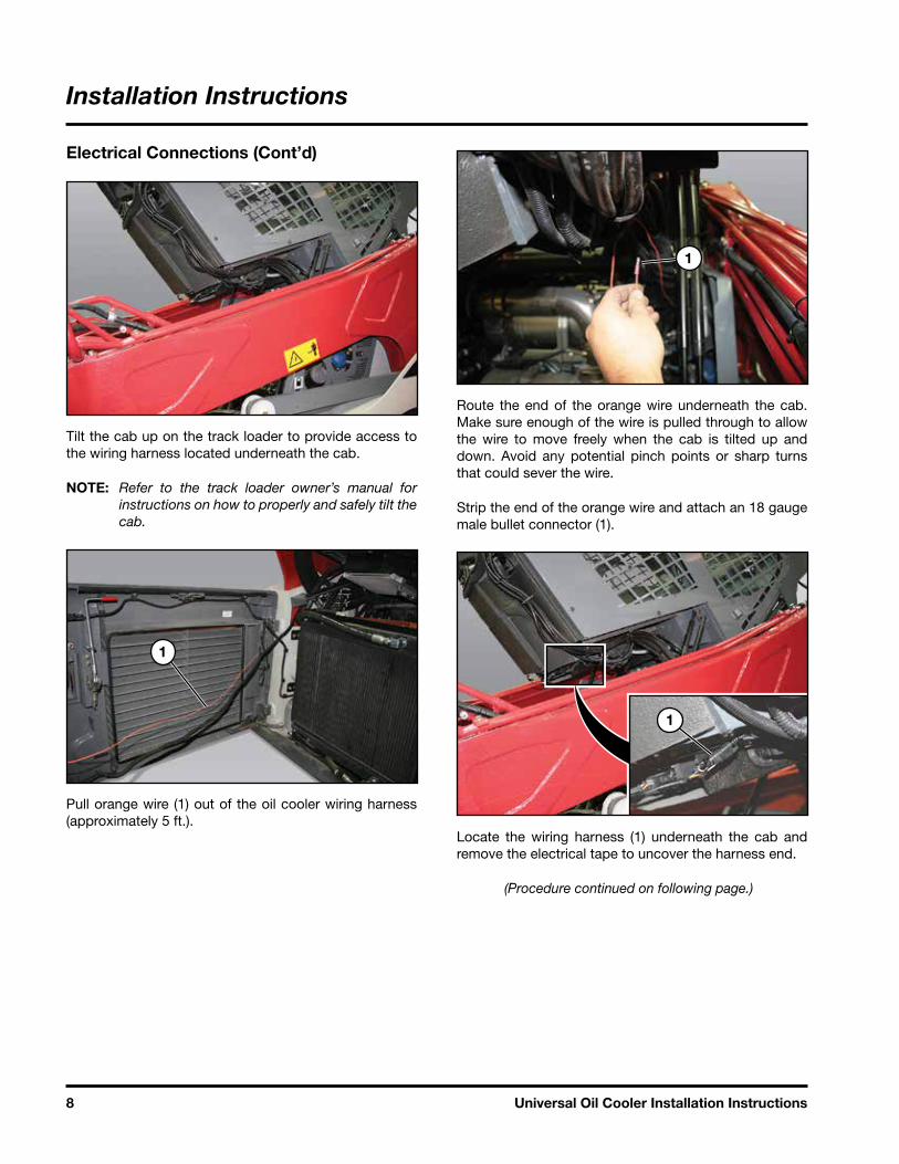
Electrical Connections (Cont’d)
Tilt the cab up on the track loader to provide access to the wiring harness located underneath the cab.
NOTE: Refer to the track loader owner’s manual for instructions on how to properly and safely tilt the cab.
1
Pull orange wire (1) out of the oil cooler wiring harness (approximately 5 ft.).
1
Route the end of the orange wire underneath the cab. Make sure enough of the wire is pulled through to allow the wire to move freely when the cab is tilted up and down. Avoid any potential pinch points or sharp turns that could sever the wire.
Strip the end of the orange wire and attach an 18 gauge male bullet connector (1).
1
Locate the wiring harness (1) underneath the cab and remove the electrical tape to uncover the harness end.
(Procedure continued on following page.)
Installation Instructions

9Universal Oil Cooler Installation Instructions
Electrical Connections (Cont’d)
1
2
Connect the orange wire (1) to the white keyed power wire (2). The white wire is equipped with a female bullet connector. Use electrical tape to secure the harness/connection back to its original position.
1
2
Secure the orange wire (1) to the track loader control wiring using tie-wraps (2).
Tilt cab on track loader back down.
1
Unfasten the three bolts and remove the battery access panel (1).
Connect the white negative (—) 8 AWG and 18 AWG wire of the oil cooler harness to the negative terminal on the battery.
Reconnect track loader's battery connection.
Place the battery access panel back into position. Reinsert the bolts and tighten.
(Procedure continued on following page.)
Installation Instructions

10 Universal Oil Cooler Installation Instructions
Electrical Connections (Cont’d)
12 Volt Power Source Connection
The 12 volt power source is accessed via the left side of the rear engine compartment.
Remove the four bolts and cover to gain access. Use a 13 mm wrench to remove the top bolts (1) and a 10 mm wrench to remove the lower bolts (2).
NOTE: The fuse block does not need to be removed from the mount to add wire.
(Procedure continued on following page.)
Installation Instructions

11Universal Oil Cooler Installation Instructions
Electrical Connections (Cont’d)
12 Volt Power Source Connection (Cont’d)
Remove the screw (1) on the wire labeled “3-OUT”.
Pull 24 in. of the red 8 AWG wire from the braided harness. Add a ring connector to the wire end.
Connect the wire (2) to the terminal (ensure wire labeled “3-OUT” is connected as well). Reinsert screw and tighten.
(Procedure continued on following page.)
Installation Instructions

12 Universal Oil Cooler Installation Instructions
Installation Instructions
Electrical Connections (Cont’d)
1
Secure the cooler wiring harness (1) to the oil cooler hydraulic hoses with tie-wraps.
Securing Hoses and Wiring Harness
Make sure the oil cooler hydraulic hoses and wiring harness are secure. Use tie-wraps where needed.
Avoid any potential pinch points or sharp turns that could cut or wear on the hoses or wires.
Provide slack in the hoses and wires to allow them to move freely when the cab is tilted up and down.
Check Hydraulic Oil Level
The oil cooler cab mount kit is shipped without hydraulic oil present. Also, some hydraulic oil may have been lost during the installation, especially when the track loader's original hoses were disconnected.
After the oil cooler cab mount kit installation, check the hydraulic oil level in the track loader. Add as needed.
NOTE: Refer to your Takeuchi TL12V2/R2 Owner's Manual for checking and adding hydraulic oil.

13Universal Oil Cooler Installation Instructions
TORQUE CHARTSMinimum Hardware Tightening Torques
Normal Assembly Applications(Standard Hardware and Lock Nuts)
STUN KCOL8 edarG EAS5 edarG EAS2 .rG EAS
Nominal Size
Unplatedor
Plated Silver
PlatedW / ZnCr
Gold
Unplatedor
Plated Silver
PlatedW / ZnCr
Gold
Unplatedor
Plated Silver
PlatedW / ZnCr
Gold
GradeW / Gr. 5
Bolt
GradeW / Gr. 8
Bolt
1/4 55 in.-lb.(6.2 N•m)
72 in.-lb.(8.1 N•m)
86 in.-lb.(9.7 N•m)
112 in.-lb.(12.6 N•m)
121 in.-lb.(13.6 N•m)
157 in.-lb.(17.7 N•m)
61 in.-lb.(6.9 N•m)
86 in.-lb.(9.8 N•m)
5/16 115 in.-lb.(13 N•m)
149 in.-lb.(17 N•m)
178 in.-lb.(20 N•m)
229 in.-lb.(26 N•m)
250 in.-lb.(28 N•m)
324 in.-lb.(37 N•m)
125 in.-lb.(14 N•m)
176 in.-lb.(20 N•m)
3/8 17 ft.-lb.(23 N•m)
22 ft.-lb.(30 N•m)
26 ft.-lb.(35 N•m)
34 ft.-lb.(46 N•m)
37 ft.-lb.(50 N•m)
48 ft.-lb.(65 N•m)
19 ft.-lb. (26 N•m)
26 ft.-lb.(35 N•m)
7/16 27 ft.-lb.(37 N•m)
35 ft.-lb.(47 N•m)
42 ft.-lb.(57 N•m)
54 ft.-lb.(73 N•m)
59 ft.-lb.(80 N•m)
77 ft.-lb.(104 N•m)
30 ft.-lb.(41 N•m)
42 ft.-lb.(57 N•m)
1/2 42 ft.-lb.(57 N•m)
54 ft.-lb.(73 N•m)
64 ft.-lb.(87 N•m)
83 ft.-lb.(113 N•m)
91 ft.-lb.(123 N•m)
117 ft.-lb.(159 N•m)
45 ft.-lb.(61 N•m)
64 ft.-lb.(88 N•m)
9/16 60 ft.-lb.(81 N•m)
77 ft.-lb.(104 N•m)
92 ft.-lb.(125 N•m)
120 ft.-lb.(163 N•m)
130 ft.-lb.(176) N•m
169 ft.-lb.(229 N•m)
65 ft.-lb.(88 N•m)
92 ft.-lb.(125 N•m)
5/8 83 ft.-lb.(112 N•m)
107 ft.-lb.(145 N•m)
128 ft.-lb.(174 N•m)
165 ft.-lb.(224 N•m)
180 ft.-lb.(244) N•m
233 ft.-lb.(316 N•m)
90 ft.-lb.(122 N•m)
127 ft.-lb.(172 N•m)
3/4 146 ft.-lb.(198 N•m)
189 ft.-lb.(256 N•m)
226 ft.-lb.(306 N•m)
293 ft.-lb.(397 N•m)
319 ft.-lb.(432 N•m)
413 ft.-lb.(560 N•m)
160 ft.-lb.(217 N•m)
226 ft.-lb.(306 N•m)
7/8 142 ft.-lb.(193 N•m)
183 ft.-lb.(248 N•m)
365 ft.-lb.(495 N•m)
473 ft.-lb.(641 N•m)
515 ft.-lb.(698 N•m)
667 ft.-lb.(904 N•m)
258 ft.-lb.(350 N•m)
364 ft.-lb.(494 N•m)
1 213 ft.-lb.(289 N•m)
275 ft.-lb.(373 N•m)
547 ft.-lb.(742 N•m)
708 ft.-lb.(960 N•m)
773 ft.-lb.(1048 N•m)
1000 ft.-lb.(1356 N•m)
386 ft.-lb.(523 N•m)
545 ft.-lb.(739 N•m)
Appendix
Torque Specifications
Inches Hardware and Lock Nuts

14 Universal Oil Cooler Installation Instructions
Appendix
Torque Specifications (Cont’d)
Metric Hardware and Lock Nuts
TORQUE CHARTSMinimum Hardware Tightening Torques
Normal Assembly Applications(Metric Hardware and Lock Nuts)
Class 5,8 Class 8,8 Class 10,9 Lock nuts
Nominal Size
Unplatedor
Plated Silver
PlatedW / ZnCr
Gold
Unplatedor
Plated Silver
PlatedW / ZnCr
Gold
Unplatedor
Plated Silver
PlatedW / ZnCr
Gold
Class 8W / CL. 8,8
Bolt
M4 1.7 N•m(15 in.-lb.)
2.2 N•m(19 in.-lb.)
2.6 N•m(23 in.-lb.)
3.4 N•m(30 in.-lb.)
3.7 N•m(33 in.-lb.)
4.8 N•m(42 in.-lb.)
1.8 N•m(16 in.-lb.)
M6 5.8 N•m(51 in.-lb.)
7.6 N•m(67 in.-lb.)
8.9 N•m(79 in.-lb.)
12 N•m(102 in.-lb.)
13 N•m(115 in.-lb.)
17 N•m(150 in.-lb.)
6.3 N•m(56 in.-lb.)
M8 14 N•m(124 in.-lb.)
18 N•m(159 in.-lb.)
22 N•m(195 in.-lb.)
28 N•m(248 in.-lb.)
31 N•m(274 in.-lb.)
40 N•m(354 in.-lb.)
15 N•m(133 in.-lb.)
M10 28 N•m(21 ft.-lb.)
36 N•m(27 ft.-lb.)
43 N•m(32 ft.-lb.)
56 N•m(41 ft.-lb.)
61 N•m(45 ft.-lb.)
79 N•m(58 ft.-lb.)
30 N•m(22 ft.-lb.)
M12 49 N•m(36 ft.-lb.)
63 N•m(46 ft.-lb.)
75 N•m(55 ft.-lb.)
97 N•m(72 ft.-lb.)
107 N•m(79 ft.-lb.)
138 N•m(102 ft.-lb.)
53 N•m(39 ft.-lb.)
M16 121 N•m(89 ft.-lb.)
158 N•m(117 ft.-lb.)
186 N•m(137 ft.-lb.)
240 N•m(177 ft.-lb.)
266 N•m(196 ft.-lb.)
344 N•m(254 ft.-lb.)
131N•m(97 ft.-lb.)
M20 237 N•m(175 ft.-lb.)
307 N•m(226 ft.-lb.)
375 N•m(277 ft.-lb.)
485 N•m(358 ft.-lb.)
519 N•m(383 ft.-lb.)
671 N•m(495 ft.-lb.)
265 N•m(195 ft.-lb.)
M24 411 N•m(303 ft.-lb.)
531 N•m(392 ft.-lb.)
648 N•m(478 ft.-lb.)
839 N•m(619 ft.-lb.)
897 N•m(662 ft.-lb.)
1160 N•m(855 ft.-lb.)
458 N•m(338 ft.-lb.)


www.loftness.com
Loftness Specialized Equipment, Inc.650 So. Main Street • PO Box 337 • Hector, MN 55342Tel: 320.848.6266 • Fax: 320.848.6269 • Toll Free: 1.800.828.7624
Printed in USA© Loftness 2017


