90
Tank Container Inspection Handbook Page | 0 Tank Container Inspection Handbook 2011Rev 1
| Date post: | 08-Jan-2016 |
| Category: |
Documents |
| Upload: | sreeram4160 |
| View: | 14 times |
| Download: | 0 times |
7/17/2019 Tank Container HandBook-2011
http://slidepdf.com/reader/full/tank-container-handbook-2011 1/90
Tank Container Inspection Handbook
Page | 0
TankContainerInspection
Handbook2011Rev 1
7/17/2019 Tank Container HandBook-2011
http://slidepdf.com/reader/full/tank-container-handbook-2011 2/90
Tank Container Inspection Handbook
Page | 1
CONTENTS
Section 1 Safety (3)
Section 2 Definiti ons and Cleaning Terminology (5)
Section 3 Completion of Tank Container Repair Estimate (14)
Appendix 3.1a ITCO Internal Shell Chart –
Surface Condition (18)
Appendix 3.1b ITCO Internal Shell Chart –
Mapping Chart (21)
Appendix 3.2 ISO Damage Location Code System (22)
Appendix 3.3 ISO Component Codes (25)
Appendix 3.4 Damage Code Description (32)
Appendix 3.5 Repair Code Description (36)
Appendix 3.6 Cost Allocation (40)
Section 4 Inspection Procedures (42)
A. Pre Repair Inspection (44)
B. Joint Survey (44)
C. Post Repair (46)
D. Combined Post-Repair & On-Hire (46)
E. Supplementary Estimate (47)
F. On-Hire Survey (47)
G. Pre-Delivery Inspection (48)
Appendix 4.1 Lessee Refuse Cost Report (49)
Section 5 Identif ication of Manufacturers' Defects (50)
Appendix 5.1 Warranty Report for New Defects (54)
Section 6 Identif ication of Frequent Misuse of Tank Containers (55)
Section 7 Improper Repairs (58)
Section 8 Inspection Guidelines for Tank Containers (ACC) (60)
Section 9 Convention for Safe Containers (CSC) (86)
Appendix 9.1 Data Plate (88)Revisions (89)
For further information please contact:
Engineering Maintenance Services (EMS)Seaco SRL80 Anson Road#29-01 Fuji Xerox Towers
Singapore 079907Tel: +65 65951900Fax: +65 56951968
7/17/2019 Tank Container HandBook-2011
http://slidepdf.com/reader/full/tank-container-handbook-2011 3/90
Tank Container Inspection Handbook
Page | 2
Section 1
SAFETY

7/17/2019 Tank Container HandBook-2011
http://slidepdf.com/reader/full/tank-container-handbook-2011 4/90
Tank Container Inspection Handbook
Page | 3
Section 1: SAFETY
Contents of Section
Safe Inspection Procedures and Practice (4)
Specific Inspection Hazards (4)
DO NOT OPERATE ANY VALVES/FITTINGS OR ENTER ANY TANK CONTAINER WHICH DOES NOTPOSSESS A VALID SAFETY DOCUMENT.
SEE SECTION 2 FOR DEFINITION OF A VALID SAFETY DOCUMENT.
INTRODUCTION
Inspections and works should be carried out in compliance with international, regional and local laws including
health and safety regulations and regulations appertaining to working in confined spaces, fire and explosions.The following is for guidance only.
SAFE INSPECTION PROCEDURES AND PRACTICE
Tank containers are designed to transport cargoes which may be dangerous. Characteristics and safetyhazards associated with specific cargoes are available from the manufacturers Material Safety Data Sheet(MSDS).
Cargoes might be transported under a blanket layer of inert gas such as nitrogen. An inert gas cannot supporthuman life; breathing any gas mixture possessing less than 19.5% of oxygen is likely to cause suffocation(asphyxiation). Prior to a thorough cleaning and ventilation, tank containers may not possess adequate oxygento sustain life or may contain harmful or explosive vapours hazardous to one's health.
Do not operate any valves/fittings or enter any tank container which does not possess a valid safety document.Comply with the MSDS.
Personnel must not enter any tank container until a tank container entry permit has been completed. Entry permits are designed to help ensure compliance with confined space entry laws and regulations of allgovernments having jurisdiction (nation, state/province, locality, etc).
Before entering a tank container the inspector must:
− Check the last cargo and safety data (MSDS) and take appropriate action.
− Check that the container has been cleaned and cleaning document issued.
− Check that the container has been adequately ventilated with fresh air to ensure a minimum oxygen content
of 19.5%.− Check the container atmosphere to determine the absence of explosive or flammable vapour or gas.
− Check that an attendant who has full knowledge of the time of entry is stationed outside the container in theimmediate vicinity and that the inspector and attendant are equipped with all safety and rescue equipment required by all applicable laws and regulations.

7/17/2019 Tank Container HandBook-2011
http://slidepdf.com/reader/full/tank-container-handbook-2011 5/90
Tank Container Inspection Handbook
Page | 4
SPECIFIC INSPECTION HAZARDS
Personnel must be mindful of certain specific hazards which could potentially arise when inspections or testing
of tank containers are performed. These include but are not limited to:− Asphyxiat ion or poison ing upon entry into an unclean container or a container possessing insufficient
oxygen.
− Sudden release of pressure from discharge valves or manlid if opened while container is under pressure. Avoid standing in front of fittings, openings or over the manlid if the possibility of sudden pressure dischargeexists. Personnel should depressurise the container vessel by carefully operating the airline valve. Do notdepressurise the container vessel by attempting to open the manlid.
− Always face away from the manlid opening when final ly crack ing and li ft ing the manlid to avo idinhalation of any potentially hazardous escaping fumes or unanticipated pressure release. Ensurethe body is not in direct line with the valve opening.
− Sudden release of steam or test pressure from steam tubes. Avoid standing in front of steam tubeopenings or quick release valves if the possibility of sudden pressure discharge exists, or when
depressurising the steam heating system. Do not rely upon steam dust caps to hold pressure.− Jamming of fingers in open valves during inspection. Do not place fingers into open valves as sudden
closure could crush fingers.
− Falling from damaged ladder or walkway. Ensure repairs to damaged sections of ladder or walkway priorto treading on them if condition is unsafe to proceed. Ensure that there is no contamination on the ladder,walkway or footwear which may cause loss of grip. Access the top of the tank via a gantry.
NOTE: ALL PERSONNEL HAVE A RESPONSIBILITY FOR THEIR OWN HEALTH AND SAFETY AND MUSTTAKE CARE TO REDUCE ANY RISKS TO AN ABSOLUTE MINIMUM.

7/17/2019 Tank Container HandBook-2011
http://slidepdf.com/reader/full/tank-container-handbook-2011 6/90
Tank Container Inspection Handbook
Page | 5
Section 2
DEFINITIONS AND CLEANING TERMINOLOGY

7/17/2019 Tank Container HandBook-2011
http://slidepdf.com/reader/full/tank-container-handbook-2011 7/90
Tank Container Inspection Handbook
Page | 6
Section 2: Definit ions and CleaningTerminology
Contents of Section
Definitions (8)
1. Damage (8)
2. Wear and Tear (8)
3. Improper Repairs (8)
4. Full Refurbishment (8)
5. Partial Refurbishment (8)
6. Re-Manufacture (8)
7. Tank (8)
8. Hazardous Tank (8)
9. Statutory Test Date (9)
10. Detachable Parts (9)11. Consequential Damage (9)
12. Cleaning Terminology (9)
a) Evidence of last cargo (9)
b) Material Safety Data Sheet (MSDS) (9)
c) Cleanliness Certificate (9)
d) Cleaning Receipt (10)
e) Entry Permit (or Safety Certificate) (10)
f) Cleaning Document (10)
g) Qualified Person (11)
h) Specialist Cleaning Contractor (11)i) Transferable Stain (11)
13. Seaco Surveyor (11)
Appendix 2.1: Cleanliness Certificate (11)
Appendix 2.2: Cleaning Receipt (12)
Appendix 2.3: EFTCO Cleaning Receipt (13)
Appendix 2.4: Entry Permit (14)

7/17/2019 Tank Container HandBook-2011
http://slidepdf.com/reader/full/tank-container-handbook-2011 8/90
Tank Container Inspection Handbook
Page | 7
DEFINITIONS
The following definitions are used in this manual:
1 Damage
Damage is one or more physical defects in a container caused by a single event or a series of events such asimpact, abrasion contamination, cargo attack, etc which exceeds the acceptable limits as defined in Section 8entitled Inspection Guidelines for Tank Containers of this handbook. This includes corrosion, pitting or gougesto the interior or exterior of the container, shell, fittings or accessories.
2 Wear and Tear
Wear and tear also referred to as Age Related Deterioration (ARD) is one or more physical defects resultinginevitably from exposure of the container to conditions for which it was designed. It precludes the existence ofany physical defect which is considered unacceptable in accordance with Seaco's Inspection Guidelines forTank Containers, as defined in Section 8 of this handbook and which may have led to the deteriorated condition. Any deterioration resulting from improper use, improper maintenance or lack of maintenance is not fair wear andtear.
3 Improper Repairs
An improper repair is any repair performed where any one of the following defects is present:
− The repair has not been performed in strict accordance with Seaco guidelines
− The repair is of a quality or condition which could still be defined as damage according to Seaco guidelines
− The repair has an adverse affect on the original ISO dimensions of the container
− The repair affects the structural integrity of the container
− Use of incorrect materials
− Sub standard preparation or painting− Poor quality welding or workmanship
− Sub-standard cleaning or polishing of the tank container or fittings
4 Full Refurb ishment
Full refurbishment is the process of removing all the paint coating and any corrosion from the container frame byabrasive blasting followed by repainting and replacing the cladding and insulation.
The insulation and cladding may be refurbished as part of a full refurbishment process. However, it is notessential for the cladding to be included in a full refurbishment process.
5 Partial Refurb ishment
Partial refurbishment is the process of renovating areas of the container to an extent less than that defined asFull Refurbishment.
6 Re-manufacture
Re-manufacture is the process of removing the frame and insulation and re-using the original tank shellin a new frame and new insulation.
7 Tank
Tank Container in its entirety (Not just the tank shell)
8 U.N. Portable Tank
Tank container designed and approved for the carriage of dangerous goods (as defined by U.N. DangerousGoods List).
7/17/2019 Tank Container HandBook-2011
http://slidepdf.com/reader/full/tank-container-handbook-2011 9/90
Tank Container Inspection Handbook
Page | 8
9 Statutory Test Date
This is the date when a periodic inspection and pressure test of the tank container was carried out to complywith the regulations of the governmental approving agencies.
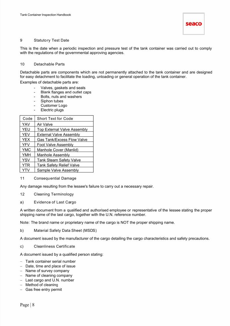
10 Detachable Parts
Detachable parts are components which are not permanently attached to the tank container and are designedfor easy detachment to facilitate the loading, unloading or general operation of the tank container.
Examples of detachable parts are:
- Valves, gaskets and seals- Blank flanges and outlet caps- Bolts, nuts and washers- Siphon tubes- Customer Logo- Electric plugs
Code Short Text for Code
YAV Air Valve
YEU Top External Valve Assembly
YEV External Valve Assembly
YEX Gas Tank/Excess Flow Valve
YFV Foot Valve Assembly
YMC Manhole Cover (Manlid)
YMH Manhole Assembly
YSV Tank Steam Safety Valve
YTR Tank Safety Relief Valve
YTV Sample Valve Assembly
11 Consequential Damage
Any damage resulting from the lessee's failure to carry out a necessary repair.
12 Cleaning Terminology
a) Evidence of Last Cargo
A written document from a qualified and authorised employee or representative of the lessee stating the propershipping name of the last cargo, together with the U.N. reference number.
Note: The brand name or proprietary name of the cargo is NOT the proper shipping name.
b) Material Safety Data Sheet (MSDS)
A document issued by the manufacturer of the cargo detailing the cargo characteristics and safety precautions.
c) Cleanliness Certificate
A document issued by a qualified person stating:
− Tank container serial number
− Date, time and place of issue
− Name of survey company
− Name of cleaning company
− Last cargo and U.N. number
−
Method of cleaning− Gas free entry permit
7/17/2019 Tank Container HandBook-2011
http://slidepdf.com/reader/full/tank-container-handbook-2011 10/90
Tank Container Inspection Handbook
Page | 9
− A thorough visual examination has been carried out and the interior of the tank container, valves and fittingsare free of pitting, corrosion, contamination, particles of previous cargo and odour
− The tank container is clean and dry
See Appendix 2.1 for an example of a cleanliness certificate.
Cleanliness Certificate Validity Date
The cleanliness certificate date of issue should be recent. An evaluation of the circumstances and the issuedate should be undertaken to ensure that the tank container has not been used since the time of issue. Forexample, allowance should be made for the transit time between the point of cleaning and the off-hire depot.Circumstances may vary and it is not possible to set a specific validity date. For certain cargo and or regulationsan entry permit/safety certificate will be necessary.
d) Cleaning Receipt (Wash Ticket)
A document issued by the qualified person of a specialist cleaning contractor responsible for the tank containercleaning stating that:
A thorough visual examination has been carried out and the interior of the tank container, valves and fittings arefree of contamination, particles of previous cargo and odour .
See Appendix 2.2 for an example of a cleaning receipt.
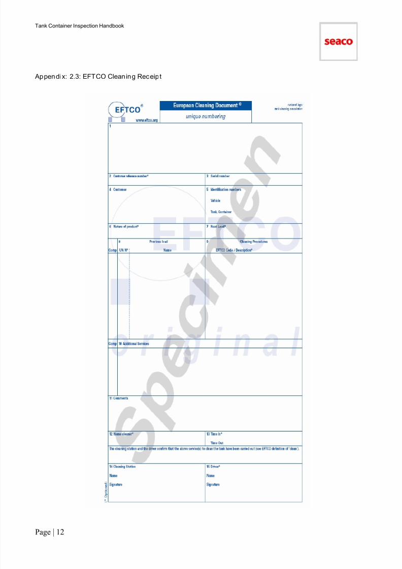
See Appendix 2.3 for an example of an EFTCO cleaning receipt.
e) Entry Permit (or Safety Certificate)
A document issued by a qualified person of the repair depot, or surveyor undertaking a risk assessment, inorder that personnel may safely carry out prescribed tasks. The document should state:
−
Tank container serial number− Date, time and place of issue
− Name of survey company
− Name of person issuing certificate
− Last cargo and U.N. number
− MSDS reference
− Period of validity of the permit
− Tests carried out (as applicable)
− Oxygen reading (gas free)
− Purpose of tank container entry
− All necessary precautions have been taken to make the tank container safe for entering and carrying outprescribed work during the specified time
See Appendix 2.4 for an example of an entry permit.
The validity of the entry permit is strictly on a limited time basis; it must be current. Any delays in carrying outsubsequent repair work may necessitate the issue of a further entry permit.f) Cleaning Document
The cleaning document is a written declaration that the tank container has been cleaned. Depending on thecircumstances a cleaning document may be the:
− Cleanliness receipt
− Cleanliness certificate
− Entry permit (safety certificate)
7/17/2019 Tank Container HandBook-2011
http://slidepdf.com/reader/full/tank-container-handbook-2011 11/90
Tank Container Inspection Handbook
Page | 10
g) Qualified Person (e.g. Surveyor, Quality Controller)
A responsible person that is properly trained, competent and experienced and is authorised by the employer orgovernmental body as is appropriate, to undertake the task.
h) Specialist Cleaning Contractor
A company of high-standing reputation skilled in tank container cleaning and licensed by appropriategovernmental agencies and a member of applicable trade organisations.
i) Transferable Stain
A stain or discoloration that can be removed from the surface of the tank shell or fittings by normal cleaningmethods including the use of a nylon abrasive Scotchbrite pad. Conversely a non transferable stain is a stainthat cannot be removed.
13 Seaco Surveyor
Any Seaco engineer or any engineer authorised by Seaco to carry out tank container inspections or surveys.
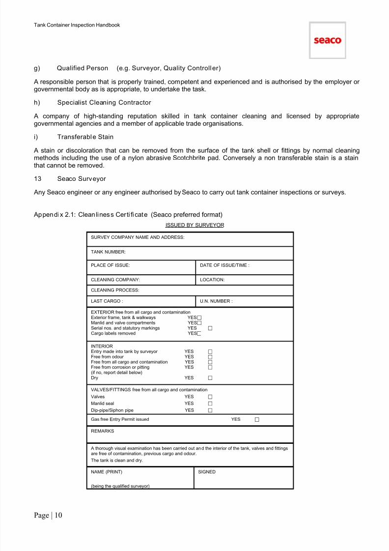
Appendi x 2.1: Cleanliness Certi fi cate (Seaco preferred format)
ISSUED BY SURVEYOR
SURVEY COMPANY NAME AND ADDRESS:
TANK NUMBER:
PLACE OF ISSUE: DATE OF ISSUE/TIME :
CLEANING COMPANY: LOCATION:
CLEANING PROCESS:
LAST CARGO : U.N. NUMBER :
EXTERIOR free from all cargo and contaminationExterior frame, tank & walkways YESManlid and valve compartments YESSerial nos. and statutory markings YES
Cargo labels removed YES
INTERIOR Entry made into tank by surveyor YES
Free from odour YES
Free from all cargo and contamination YES
Free from corrosion or pitting YES
(if no, report detail below)Dry YES
VALVES/FITTINGS free from all cargo and contamination
Valves YES
Manlid seal YES
Dip-pipe/Siphon pipe YES
Gas free Entry Permit issued YES
REMARKS
A thorough visual examination has been carried out and the interior of the tank, valves and fittingsare free of contamination, previous cargo and odour.
The tank is clean and dry.
NAME (PRINT)
(being the qualified surveyor)
SIGNED

7/17/2019 Tank Container HandBook-2011
http://slidepdf.com/reader/full/tank-container-handbook-2011 12/90
Tank Container Inspection Handbook
Page | 11
Appendix: 2.2: Cleaning Receipt
(Wash Ticket)
ISSUED BY CLEANING COMPANY
CLEANING COMPANY NAME AND ADDRESS:
*
* TANK NO:
* PLACE OF ISSUE:
* DATE OF ISSUE/TIME :
* CLEANING PROCESS:
* LAST CARGO :
* U.N. NO. :
Gas free Entry Permit issued YES
REMARKS
* A thorough visual examination has been carried out and the interior of the tank, valves andfittings are free of contamination, previous cargo and odour.
The tank is clean and dry. YES
* NAME (PRINT) SIGNED
(being the qualified surveyor)
The cleaning receipt as a minimum must contain the details marked *.
7/17/2019 Tank Container HandBook-2011
http://slidepdf.com/reader/full/tank-container-handbook-2011 13/90
Tank Container Inspection Handbook
Page | 12
Appendix: 2.3: EFTCO Cleaning Receipt

7/17/2019 Tank Container HandBook-2011
http://slidepdf.com/reader/full/tank-container-handbook-2011 14/90
Tank Container Inspection Handbook
Page | 13
Appendix 2.4: Ent ry Perm it
(Safety Certificate)
ISSUED BY DEPOT/SURVEYOR
ISSUED BY DEPOT - NAME AND ADDRESS:
ISSUED BY SURVEYOR – SURVEY COMPANY NAME AND ADDRESS:
TANK NO:
PLACE OF ISSUE: DATE OF ISSUE/TIME :
CLEANING PROCESS:
LAST CARGO : U.N. NO. :
VALID FROM:
TO:
DATE
DATE
TIME
TIME
PURPOSE OF TANK ENTRY
TESTS OF CONTAMINATES AND ATMOSPHERE IN THE TANK
TEST TYPE RESULT SATISFACTORY
YES/NO
Safety equipment to be worn by person making entry into tank
A full examination of the hazard of the tank has been carried ou t and the appropriate safety testscompleted with acceptable results.
The tank is safe to enter.
NAME (PRINT)
(being the qualified surveyor)
SIGNED
7/17/2019 Tank Container HandBook-2011
http://slidepdf.com/reader/full/tank-container-handbook-2011 15/90
Tank Container Inspection Handbook
Page | 14
Section 3
COMPLETION OF TANK CONTAINERREPAIR ESTIMATE
AND
COMPLETION OF INTERNAL SHELL CONDITION CHART
7/17/2019 Tank Container HandBook-2011
http://slidepdf.com/reader/full/tank-container-handbook-2011 16/90
Tank Container Inspection Handbook
Page | 15
Contents of Section
Completion of Tank Container RepairEstimate (17)
1. Last Cargo (17)
2. Test Date (17)
3. Container Grading (17)
4. Component (17)
5. Damage Codes (17)
6. Repair Codes (19)
7. Damage/Dimensions – Remarks (19)
Internal Shell Condition Chart (19)
Appendix 3.1a: ITCO Internal Shell Chart –
Surface Condition (21)
Appendix 3.1b: ITCO Internal Shell Chart –Mapping Chart (22)
Appendix 3.2: ISO Damage Location Code (23)
Appendix 3.3: ISO Component Codes (26)
Appendix 3.4: Damage Code Description (33)
Appendix 3.5: Repair Code Description (37)
Appendix 3.6: Cost Allocation (41)
Section 3: Completion of Tank ContainerRepair Estimate andCompletion of Internal Shell
Condition Chart

7/17/2019 Tank Container HandBook-2011
http://slidepdf.com/reader/full/tank-container-handbook-2011 17/90
Tank Container Inspection Handbook
Page | 16
COMPLETION OF TANK CONTAINER REPAIR ESTIMATE
The following instructions are for the benefit of depots that prepare manual repair estimates (RE).
Introduction
A repair estimate (RE) (which performs the function of off-hire damage report) must be completed by the depotfor every tank container entering the depot off lease or unavailable condition.
Freemove units moved in status ‘AVLB’ condition or new units ex manufacturer must be checked to ensure theyhave not suffered transit damage. If such units have transit damage then a repair estimate must be completedfor that unit.
Listed below are descriptions of the entries that must be made in each section.
* Depots should , if possible, report the repair estimate via EDI using their depot management system.
1. Last Cargo
Enter the proper shipping name and U.N. number of the last cargo carried.
Note: Abbreviations o f the cargo name, brand name or propr ietary name are not acceptable.
The depot must be in receipt of a safety document stating the proper name of the last cargo, together with theU.N. reference number, prior to carrying out the inspection. Additionally, information concerning last cargo will have already been advised in writing by the local SeacoOperations Centre prior to redelivery.
It is vital, both for the safety of personnel and in order to convey last cargo data to the next user of the tankcontainer, that the last cargo data is accurate in every detail.
If the information is missing or incomplete for any reason, the depot must contact the last lessee or SeacoCustomer Service Centre.
Do not enter incorrect or incomplete information.
2. Test Date
This refers to the last 2.5/5 year statutory pressure test. Enter date of last test shown on the tank container dataplate.
Note: Refer to Section 8.13c to determine when the statutory testing must be performed.
3. Container Grading
Unlike other SEGU equipment types there are no grading procedures applicable for tank containers.
4. Component
If estimating with the ISO coding system use the 3 digit alpha codes to denote the component.
Enter the 3 digit alpha code shown on the component list for any item which is damaged.
Appendix 3.3 shows a list of tank container components.
5. Damage Codes
Use the 2 digit alpha codes ISO coding system to denote the damage.
Only note damages that exceed the acceptable limits, as defined in Section 8 (Inspection Guidelines for TankContainers)
See Appendix 3.4 for the full description of all damages codes applicable to tank containers.
Depending upon the location submitting the estimate the damage code used to describe any particular damagemay automatically allocate the costs of the repair. Therefore, the damage code system has important
operational as well as technical implications.
Where automatic cost allocation does not take place then the depot will assign the damage responsibility.

7/17/2019 Tank Container HandBook-2011
http://slidepdf.com/reader/full/tank-container-handbook-2011 18/90
Tank Container Inspection Handbook
Page | 17
Notes on the use of damage codes:
(i) Damage codes must always be used as a single code. A combination of two or more codes to describedamage to any individual item is not permitted.
(ii) Improper Repairs (Codes IO & IR)
There are two possible codes which can be used:
IO: Improper Repair - Old
IR: Improper Repair - New
The inspector must decide by reference to the on-hire date whether the improper repair was carried outduring the most recent lease (Code IR), or before it (Code IO).
(iii) Damage caused by Rust(Code CO)
Code (CO) must be used only in clearly defined circumstances as follows:
(a) It must be used as a single code in any line of the repair estimate to describe damage caused by rustwhich is not a result of a manufacturer's defect or cargo attack or contamination. The nature of the damagewill be sufficiently implied in the appropriate repair code(s) which are entered in the adjoining column. (b) It must be used in any line of the repair estimate to describe rust, as defined in (a) above, whichrequires rectification, by partial refurbishment.
(c) In the case of a full refurbishment of a tank container damage code CO can only be used for tankcontainers which are more than 5 years old or which are subject to a refurbishment Tank Technical Bulletin(TTB).
For tank containers less than 5 years old use damage code MN (New Manufacturing Defect) or CD
(Consequential Damage).
(iv) Consequential Damage – (Code CD)
Must be used for any damage resulting from the Lessee's failure to carry out a necessary repair. See Appendix 3.4 below for a full description of the use of damage code CD.
(v) Manufacturers' Defects(Codes ME and MN)
There are two possible codes which can be used:
ME: Manufacturers' Defect - ExistingMN: Manufacturers' Defect - New
(a) Code ME must be used to describe damage caused by a manufacturers' defect which is subject to a TTB.The TTB identifies the series of tank containers affected and gives instructions on repair method andreporting procedure.
(b) Code MN must be entered to describe 'new' defects i.e. not yet identified by TTB.
See Section 5 regarding the procedure for reporting both existing and new manufacturers' defects.
7/17/2019 Tank Container HandBook-2011
http://slidepdf.com/reader/full/tank-container-handbook-2011 19/90
Tank Container Inspection Handbook
Page | 18
(vi) Allocation of Costs
The allocation of repair costs between the two principal account categories, Lessee and Seaco, is determined bythe damage code or by the depot assigning responsibility, depending upon how the depot is set-up.
Appendix 3.4 shows the damage codes which must be used in each of the circumstances defined.
The first heading entitled ANY ITEM covers all components of the tank container.
6. Repair Codes
ISO Codes
See Appendix 3.5 for the full list of repair codes.7. Damage/Dimensions - Remarks
Specify the quantity and extent of repair requirement against each damaged component.The type of damage and repair method proposed should have already been noted in the damage and repaircodes. Therefore, no description of the damage and repair methods is required except in the case of damagesor repair methods that cannot be adequately described by use of the coding system.Note: - All dimentions to be metric.
INTERNAL SHELL CONDITION CHART Introduction
Whenever there is evidence of interior tank stains, shell pitting, rust, scoring, scratches, gouges or any otherunsatisfactory internal condition, this must be documented on the Tank Container Interior Shell Chart. See
Appendix 3.1 for an example of form.The Inspector enters the following information when completing the form:
1. Standing Data
Tank Container Serial NumberEnter tank container prefix, serial number and check digit
Depot/Location
Enter depot name, or preferably, Seaco depot code for depot location at which inspection is performed
DateEnter date of inspection
Report ByEnter inspector's name
Inspector SignatureEnter inspector's signature (at bottom of form)
Tank Container Unit TypeEnter Seaco tank unit type code
Tank Container Material
Enter barrel material, i.e. AISI Type 316 steel, or if lined tank container, identify lining material
Last CargoEnter the proper name of the last cargo
U.N. Number
Enter U.N. reference number
7/17/2019 Tank Container HandBook-2011
http://slidepdf.com/reader/full/tank-container-handbook-2011 20/90
Tank Container Inspection Handbook
Page | 19
2. Shell Condition
Complete the chart using the surface condition key provided. Show measurements for affected areas whenever
feasible.
Pitting Shape
Indicate most prevalent shape of pits seen, when pits are present. Tick flat bottom, pin hole, crater or cavity asappropriate.
Approx imate Pi tt ing Size
Provide pit measurement size for depth and diameter (in mm), or if pit size varies, identify size as appropriate onthe map.
Area of Shel l Affected
For any condition indicate the percentage of area of the shell interior affected and remark whether the areaaffected follows any pattern e.g. above/below cargo ullage line, heated area only, dished ends and weld-inflanges equally pitted etc.
Discoloration / Stains
Indicate the colour of any discoloration, and notate transferable or non transferable.
Condition of Fittings
Indicate if any of the condition(s) shown in the surface condition key are present on the siphon tube, weld-inflanges, manlid neck ring, manlid or valves; indicate the extent, location, and specific characteristics of thecondition(s) found.
Addi tional Remarks
Use the space for additional comments as needed.

7/17/2019 Tank Container HandBook-2011
http://slidepdf.com/reader/full/tank-container-handbook-2011 21/90
Tank Container Inspection Handbook
Page | 20
Appendix 3.1a: ITCO Interior Shel l Chart - Surface Condi tion
7/17/2019 Tank Container HandBook-2011
http://slidepdf.com/reader/full/tank-container-handbook-2011 22/90
Tank Container Inspection Handbook
Page | 21
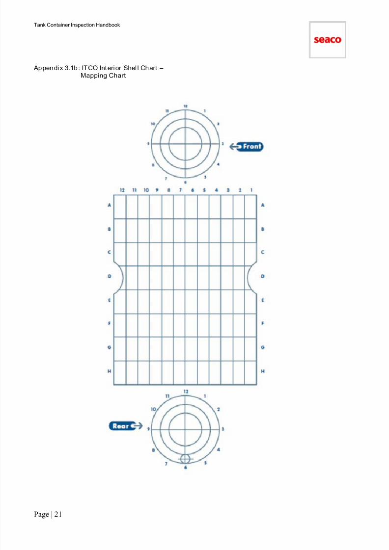
Appendix 3.1b : ITCO Interior Shel l Chart –Mapping Chart

7/17/2019 Tank Container HandBook-2011
http://slidepdf.com/reader/full/tank-container-handbook-2011 23/90
Tank Container Inspection Handbook
Page | 22
Appendix 3.2: ISO Damage Locat ion Code System
Tank container components have their location identified by alpha codes (up to 4 characters in length).
Appendix 3.3 below notes the components by section. The location code for each component is notedalongside the component. Only location codes noted alongside the component may be used.
Damages will be located by panel(s). For the purpose of locating damages, the tank container is dividednominally into 4ft x 4ft (120cm x 120cm) segments.
A tank container frame locat ion code consists of four characters depending upon the area contain ingthe entire vertical and horizontal length of the damage.
Location Code 1
1. The first character is selected to identify the appropriate face of the tank container as follows:
• R Right Side• L Left Side
• T Top
• B Bottom (Floor)
• F Front End
• D Ladder & Data Plate End
• U Understructure
• X Whole Container
• I Container Interior
• E
Container Exterior
Location Code 2
2. The second character is selected to identify the appropriate part of the tank container face where thedamage is contained. To do this the vertical faces of the tank container are divided into the top and bottomhalves and upper and lower main components; the horizontal faces of the tank container (roof or top andfloor or bottom and understructure) are divided into right and left halves when viewed from the rear end.
The relevant codes are:
• H Upper (Higher) Component
• T Top Half
• B Bottom (Lower) Component
• G Lower Component (Ground)
• L Left Half
• R Right Half
• X Both Halves (i.e. Top/Bottom,Left/Right, Centre)

7/17/2019 Tank Container HandBook-2011
http://slidepdf.com/reader/full/tank-container-handbook-2011 24/90
Tank Container Inspection Handbook
Page | 23
Location Code 3
3. The third and fourth characters are selected to identify the section of the tank container in which the damageis contained.
a) On all containers the front and rear ends are divided into the vertical section numbered, when viewedfrom the rear end from left to right.
1 - For the left hand side corner post2 - for the left half3 - for the right half4 - for the right hand side corner post
b) On all containers the right and left sides, the roof, the floor and the understructure are divided into equalsections as follows: 5 sections - 1 through 5
c) When the damage covers one section only, the third character indicates the appropriate section number
and the fourth character shall be filled in with ‘N’.
d) When the damage covers several adjacent sections the first and last section shall be employed.
e) When the damage covers several non-adjacent sections or if the damage/ repair details are not thesame, then separate line items must be used.
f) When the damage covers the entire length of the container face, the third and fourth characters are filledin with ‘X’.
Location Code 4
4. Numbering system for multiple components.
a) In addition to the above described location code some components are more precisely identified innumerical order.
b) The particular components of the rear and front end are numbered consecutively from left to right whenviewed from the rear end.
c) The particular components contained in all other faces such as side posts, crossmembers arenumbered consecutively from the rear end.
d) When the damage covers several faces of the inside of the container such as steam cleaning, polishingthe code IXXX shall be used.
e) When the damage covers several faces of the outside of the container such as refurbishment, refixing orsealing cladding panels removal of cargo stickers the code EXXX shall be used.
7/17/2019 Tank Container HandBook-2011
http://slidepdf.com/reader/full/tank-container-handbook-2011 25/90
Tank Container Inspection Handbook
Page | 24
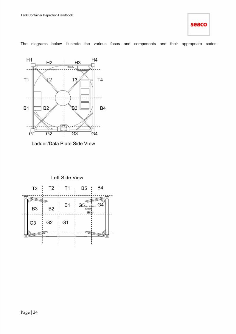
The diagrams below illustrate the various faces and components and their appropriate codes:
Ladder/Data Plate Side View
H2 H3 H4 H1
T2 T3 T4 T1
B2 B3 B4 B1
G2 G3 G4 G1
Left Side View
G1 G2 G3
G4 G5 B1 B2 B3
B4 B5 T1 T2 T3

7/17/2019 Tank Container HandBook-2011
http://slidepdf.com/reader/full/tank-container-handbook-2011 26/90
Tank Container Inspection Handbook
Page | 25
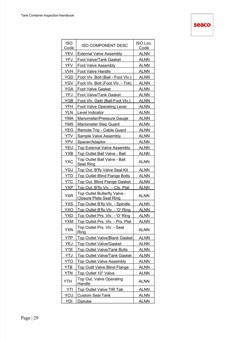
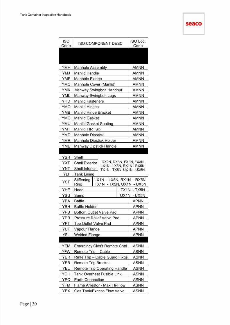
Appendix 3.3: ISO Component Codes
ISO
Code
ISO COMPONENT DESCISO Loc.
CodeTank Rails (Location = AANN)
YLA Ladder AANN
YLG Ladder Handle AANN
KWL Ladder Landing (Tank) AANN
YHA Hand Rail Assembly AANN
YWA Walkway AANN
YWF Walkway Fittings AANN
YWM Walkway Mount Bracket AANN
Tank Spill Box (Location = ABNN)
YVC Btm Valve Compartment ABNN
YVL Btm Valve Compartment Cover ABNN
YVH Btm Valve Compartment Hinge ABNN
YDC Tank Drain Tube X-Wire ABNN
YDT Tank Draining Tube ABNN
YSP Tank Spill Box ABNN
YBC Tank Spill Box Cover ABNN
YSB Tank Spill Box Hinge ABNN
YSQ Tank Spill Box TIR Tab ABNN
YLO Spill Box Lock ABNN
Tank Markings (Location = ADNN)
YAA AAR Markings
LNNN,RNNN, ADNN
LNNN,
RNNN, ADNN
YBM BAM Marking
YCT CTC Markings
MCA Caution Marking
YPM Product Marking
YPP Product Plate Holder
YRI RID/ADR Markings
YRT RTMD Markings
MST Size Marking
YUI UIC Markings
MCU Operator Marking
YFR FRA Markings
MHT Height Marking
YDO DOT Markings
MMI Weight Marking DNNN, ADNN
MCC Country Code LNNN, RNNN, DNNN,FNNN, ADNNMOL Owner’s Logo
MIS ID SetLNNN, RNNN, DNNN,FNNN, TX1N, TX5N,
ADNN
MSD Markings Digit
MFS Markings Set
MOC Owner’s Code
MPL Cargo Plate ADNN
MPD Consolidated Data Plate ADNN

7/17/2019 Tank Container HandBook-2011
http://slidepdf.com/reader/full/tank-container-handbook-2011 27/90
Tank Container Inspection Handbook
Page | 26
ISOCode
ISO COMPONENT DESCISO Loc.
Code
MPS CSC Plate ADNN
MCE ACEP Marking ADNNMPC Customs Plate ADNN
YEA Earth Connection Marking ADNN
YEW Electrical Wiring Marking ADNN
YFU FLA Plate ADNN
MPO Owner’s Plate ADNN
YTA Tank Plate ADNN
YCC Calibration Chart ADNN
MPM Manufacturer’s Plate ADNN
MRU Markings Other ADNN
Tank Frame (Location = AFNN)YWA Walkway AFNN
YWB Walkway/Replace Large AFNN
YWC Walkway/Replace Med AFNN
YWD Walkway/Replace Small AFNN
YWF Walkway Fittings AFNN
YWM Walkway Mount Bracket AFNN
YTF Tank Frame AFNN
YVP Vertical post AFNN
RLA Side Rail
LH1N - LH5N, LG1N - LG5N,RH1N - RH5N, RG1N - RG5N.
LH12 - LH45, LG12 - LG45,RH12 - RH45, RG12 - RG45,LH13 - LH35, LG13 - LG35,
RH13 - RH35, RG13 - RG35,LH14 - LH25, LG14 - LG25,
RH14 - RH25, RG14 - RG25,LH15, LG15, RH15, RG15,
DG2N, DG3N, DG23, DH2N,DH3N, DH23, FG2N, FG3N,FG23, FH2N, FH3N, FH23.
RLCSide RailConsani
YHRHorizontalRail
RLG Rail Gusset
DB2N, DB3N, DT2N, DT3N,FB2N, FB3N, FT2N, FT3N,LB1N, LB5N, LT1N, LT5N,
RB1N, RB5N, RT1N, RT5N,TL1N, TL5N, TR1N, TR5N,UL1N, UL5N, UR1N, UR5N.
CFG Corner FittingDG1N, DG4N, DH1N,DH4N, FG1N, FG4N,
FH1N, FH4N
CPA Corner Post
DB1N, DT1N, DX1N,DB4N, DT4N, DX4N,FB1N, FT1N, FX1N,FB4N, FT4N, FX4N.
YDH Document Holder AFNN
YDG Doc. Holder Cap & Chain AFNN
YDF Doc. Holder Fixing Bolts AFNNYDR Diagonal Brace/bearer D*,L* ,R*,
F*, T*, U*,YFF Frame Fasteners

7/17/2019 Tank Container HandBook-2011
http://slidepdf.com/reader/full/tank-container-handbook-2011 28/90
Tank Container Inspection Handbook
Page | 27
ISOCode
ISO COMPONENT DESCISO Loc.
Code
YTG Frame Gusset/Stiffener AFNN
YMP Frame Strap Mount PadYFS Frame Strap
YEC Earth Connection AFNN
RCI Rail cone protector recess AFNN
YLT Load Transfer Area AFNN
KGD Rear Beam Guide (Tank) AFNN
YSA Saddle AFNN
YSK Skirt D*, F*, AFNN
Tank Heating (Location = AHNN)
TMT Cargo Thermostat AHNN
CBB Circuit Breaker 2 Amp AHNNCBR Circuit Breaker 20 Amp AHNN
SMN Elec.On/Off Switch AHNN
SVS Elec. Volt. Switch AHNN
LIT Electric Lamp AHNN
BEA Electrical Control Box AHNN
YEH Electrical Heating Element AHNN
YID Electrical Instruction Decal AHNN
WIR Electrical Wiring AHNN
BEG Control Box Door Gasket AHNN
YHC Heating Element Cap AHNNYET Heating Terminal Block AHNN
ECB Mains Cable 460 Volt AHNN
EPL Mains Plug 460 Volt AHNN
YSI Steam Inlet/Outlet AHNN
YDV Steam Trap AHNN
YSE Steam Tubes AHNN
YSV Tank Steam Safety Valve AHNN
YSL Tank Steam Line Cap AHNN
YTM Tank Thermometer AHNN
YTW Thermometer Receptacle AHNN
Tank Insulation (= AINN)
YIG Cladding - GRP
DX2N, DX3N,FX2N, FX3N,LX1N - LX5N,RX1N - RX5N,TX1N - TX5N,UX1N - UX5N,
AINN
YIZ Cladding - Stainl. Steel
YIC Cladding - Aluminum
YIN Insulation - Foam
PRV Cladding Rivets
YCD Cladding Support
YCS Tank Cladding Strap
YCR Cladding Strap Rivets
YSN Sun Shield AINN
YTS Sun Shield Support AINN
YTM Tank Thermometer AINN
Tank Loading /Unloading (= ALNN)

7/17/2019 Tank Container HandBook-2011
http://slidepdf.com/reader/full/tank-container-handbook-2011 29/90
Tank Container Inspection Handbook
Page | 28
ISOCode
ISO COMPONENT DESCISO Loc.
Code
YAV Air Valve ALNN
YAP Airline Pipe ALNNYAB Airline Valve – Ball ALNN
YAS Airline Valve - Ball Seating ALNN
YAE Airline Valve (1.5") Flange ALNN
YAT Airline Valve (1.5") Screw ALNN
YAF Airline Valve (2") Flanged ALNN
YAU Airline Valve (2") Screwed ALNN
YAG Airline Valve/Tank Gasket ALNN
YCA Airline Valve Cap ALNN
YAC Airline Valve Cap (1.5”) ALNN
YCG Airline Valve Cap Seal ALNNYAD Airline Valve Cap (2") ALNN
YAW Weld-in Flange/Airline Valve ALNN
YXW Weld-in Flange/3” Valve ALNN
YZW Weld-in Flange/2” Valve ALNN
YYW Weld-in Flange/1.5” Valve ALNN
YBF Blind Flange ALNN
YGH Bolts (Bottom/Foot Valve) ALNN
YBD Btm Outlet Ball Valve - Ball ALNN
YBR Btm Out. Vlv. - Ball Seat Ring ALNN
YBP Btm Outlet B’fly Vlv. -Clos Plt ALNN
YBKBtm Outlet Butterfly Valve -Closure Plate Seat Ring
ALNN
YBO Btm Out. B’fly Vlv. - 'O' Ring ALNN
YBS Btm Out. B’fly Vlv.- Spindle ALNN
YFC Btm Outlet Cap and Chain ALNN
YFG Btm Outlet Cap Seal ALNN
YFO Btm Outlet Foot Vlv. - 'O' Ring ALNN
YFP Btm Outlet Foot Vlv. – Prs. Plat ALNN
YFKBtm Outlet Foot Vlv. - SeatRing
ALNN
YFN Btm Outlet Foot Vlv. - Spring ALNN
YFD Btm Outlet Valve/Blank Bolts ALNN
YFE Btm Outlet Valve/Blank Gasket ALNN
YBB Btm Outlet Valve/Foot Bolts ALNN
YBG Btm Outlet Valve/Foot Gasket ALNN
YBV Btm Outlet Valve Assembly ALNN
YFB Btm Outlet Valve Blind Flange ALNN
YBL Btm Outlet Valve Handle ALNN
YFABtm Outlet Valve SpigotFlange
ALNN
YBT Btm Outlet Valve TIR Tab ALNNYBW Weld-in Flange/Btm Outlet Vlv. ALNN
YCO Coupling ALNN
7/17/2019 Tank Container HandBook-2011
http://slidepdf.com/reader/full/tank-container-handbook-2011 30/90
Tank Container Inspection Handbook
Page | 29
ISOCode
ISO COMPONENT DESCISO Loc.
Code
YEV External Valve Assembly ALNN
YFJ Foot Valve/Tank Gasket ALNNYFV Foot Valve Assembly ALNN
VVH Foot Valve Handle ALNN
YGD Foot Vlv. Bolt (Ball - Foot Vlv.) ALNN
YGV Foot Vlv. Bolt (Foot Vlv. - Tnk) ALNN
YGA Foot Valve Gasket ALNN
YFJ Foot Valve/Tank Gasket ALNN
YGB Foot Vlv. Gskt (Ball-Foot Vlv.) ALNN
YFH Foot Valve Operating Lever ALNN
YLN Level Indicator ALNN
YMA Manometer/Pressure Gauge ALNNYMS Manometer Step Guard ALNN
YEG Remote Trip - Cable Guard ALNN
YTV Sample Valve Assembly ALNN
YPV Spacer/Adaptor ALNN
YEU Top External Valve Assembly ALNN
YXB Top Outlet Ball Valve - Ball ALNN
YXCTop Outlet Ball Valve - BallSeat Ring
ALNN
YGJ Top Out. B'fly Valve Seal Kit ALNN
YTD Top Outlet Blind Flange Bolts ALNN
YTC Top Out. Blind Flange Gasket ALNN
YXP Top Out. B’fly Vlv. – Cls. Plat ALNN
YXRTop Outlet Butterfly Valve -Closure Plate Seat Ring
ALNN
YXS Top Outlet B’fly Vlv. - Spindle ALNN
YXO Top Outlet B’fly Vlv. - 'O' Ring ALNN
YXD Top Outlet Prs. Vlv. - 'O' Ring ALNN
YXM Top Outlet Prs. Vlv. - Prs. Plat ALNN
YXNTop Outlet Prs. Vlv. - SeatRing
ALNN
YTP Top Outlet Valve/Blank Gasket ALNNYEJ Top Outlet Valve/Gasket ALNN
YTE Top Outlet Valve/Tank Bolts ALNN
YTJ Top Outlet Valve/Tank Gasket ALNN
YTO Top Outlet Valve Assembly ALNN
YTB Top Outlt Valve Blind Flange ALNN
YTN Top Outlet 10” Valve ALNN
YTHTop Out. Valve OperatingHandle
ALNN
YTI Top Outlet Valve TIR Tab ALNN
YCU Custom Seal Tank ALNN
YDI Diptube ALNN
7/17/2019 Tank Container HandBook-2011
http://slidepdf.com/reader/full/tank-container-handbook-2011 31/90
Tank Container Inspection Handbook
Page | 30
ISOCode
ISO COMPONENT DESCISO Loc.
Code
Tank Manhole (Location = AMNN)
YMH Manhole Assembly AMNN
YMJ Manlid Handle AMNN
YMF Manhole Flange AMNN
YMC Manhole Cover (Manlid) AMNN
YMK Manway Swingbolt Handnut AMNN
YML Manway Swingbolt Lugs AMNN
YHD Manlid Fasteners AMNN
YMO Manlid Hinges AMNN
YMB Manlid Hinge Bracket AMNNYMG Manlid Gasket AMNN
YMU Manlid Gasket Seating AMNN
YMT Manlid TIR Tab AMNN
YMD Manhole Dipstick AMNN
YMR Manhole Dipstick Holder AMNN
YME Manway Dipstick Handle AMNN
Tank Pressure Vessel (= APNN)
YSH ShellDX2N, DX3N, FX2N, FX3N,LX1N - LX5N, RX1N - RX5N,
TX1N - TX5N, UX1N - UX5N.
YXT Shell Exterior
YNT Shell Interior
YLI Tank Lining
YSTStiffeningRing
LX1N - LX5N, RX1N - RX5N,TX1N - TX5N, UX1N - UX5N
YHE Head TX1N - TX5N
YSU Sump UX1N - UX5N
YBA Baffle APNN
YBH Baffle Holder APNN
YPB Bottom Outlet Valve Pad APNN
YPR Pressure Relief Valve Pad APNN
YPT Top Outlet Valve Pad APNN
YUF Vapour Flange APNN
YFL Welded Flange APNN
Tank Safety Devices (= ASNN)
YEM Emerg'ncy Clos’r Remote Cntrl ASNN
YFW Remote Trip – Cable ASNN
YER Rmte Trip – Cable Guard Fixgs ASNN
YEB Remote Trip Bracket ASNN
YEL Remote Trip Operating Handle ASNN
YOH Tank Overheat Fusible Link ASNN
YEC Earth Connection ASNN
YFM Flame Arrestor - Maxi Hi-Flow ASNN
YEX Gas Tank/Excess Flow Valve ASNN

7/17/2019 Tank Container HandBook-2011
http://slidepdf.com/reader/full/tank-container-handbook-2011 32/90
Tank Container Inspection Handbook
Page | 31
ISOCode
ISO COMPONENT DESCISO Loc.
Code
YISInternal Safety Valve, Gas
Tank
ASNN
YTR Tank Safety Relief Valve ASNN
YFT Relief valve Flame Trap ASNN
YGF Sfty Vlv. Hi-Flow PTFE Seals ASNN
YGV Sfty Valve Hi-Flow Viton Seals ASNN
YSR Safety Relief Flange ASNN
YPI Safety Rlf. Vlv. - Inr Prs. Sprg ASNN
YVS Safety Rlf. Vlv. – Vac. Sprg ASNN
YTQ Safety Relief Valve Gasket ASNN
YSW Weld-in Flng/Safety Relief Vlv. ASNN
YRU Tank Rupture Disc ASNNYRD Tank Rupture Disc Holders ASNN
YRG Bursting Disc Gasket ASNN
YRM Tank Sfty Release Manom’t’r ASNN
Miscellaneous Tank (= AZNN)
YTT 2.5 Year Statutory Test AZNN
YTX 5 Years Statutory Test AZNN
YCI Inspect & Issue Clean Cert. AZNN
YGC Inspect & Issue Gas Free Cert. AZNN
YSC Inspect/Issue Safety Cert. AZNN
YTL Leak Test (Barrel/Valves etc) AZNN
YTK Spark Test AZNN
HWR Hardware, Screws, Bolts AZNN
YWN Tank Washing Nozzles AZNN
BUL Tank Technical Bulletin AZNN
ZZZ No Component Code AZNN
PREFERRED ISO CODES
Ensures that this translation will still give the required allocation of costs for damage codes and that repaircodes indicate the correct repair method.

7/17/2019 Tank Container HandBook-2011
http://slidepdf.com/reader/full/tank-container-handbook-2011 33/90
Tank Container Inspection Handbook
Page | 32
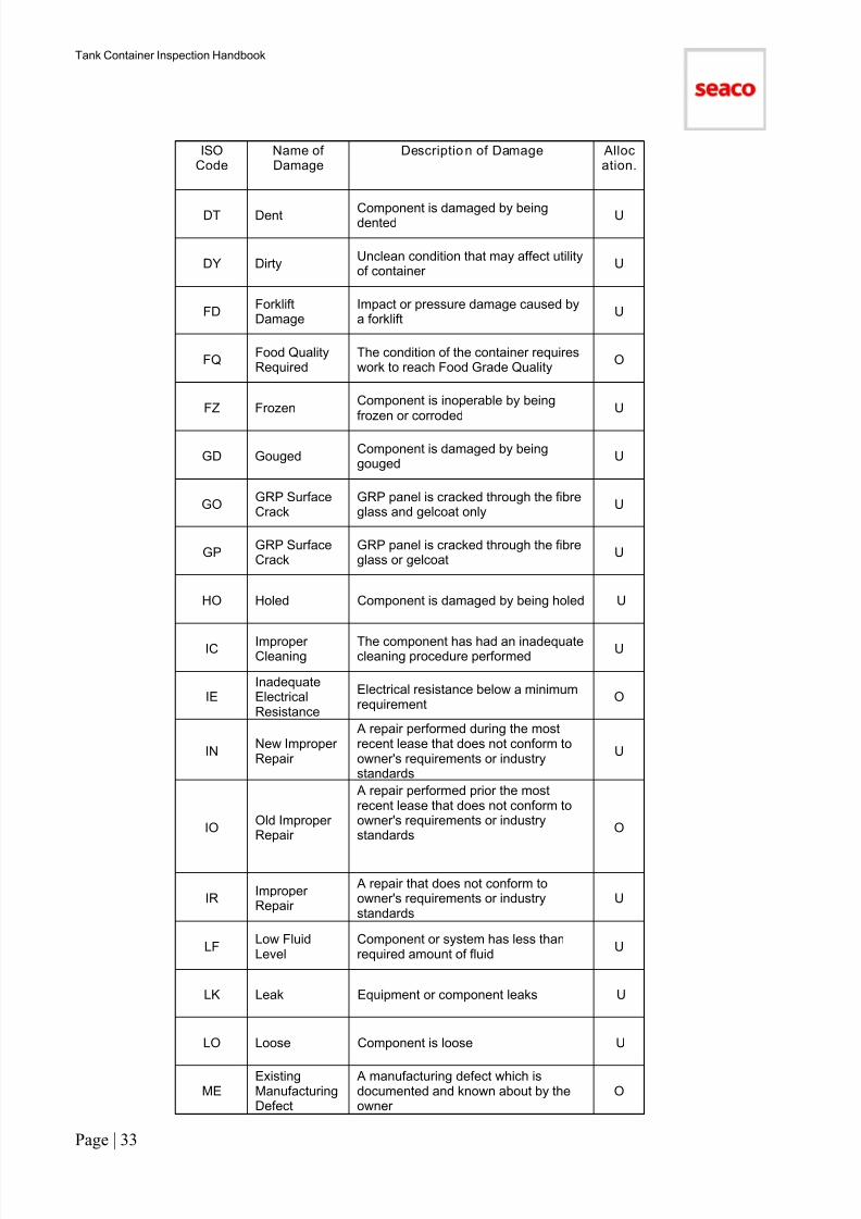
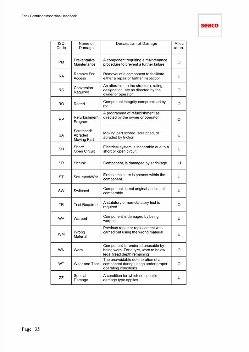
Appendix 3.4: Damage Code Descript ion
ISOCode
Name ofDamage
Description of Damage Allocation.
BK Blocked Drain, tube, outlet, etc. is blocked U
BN BurnedComponent whose surface is damagedby burns
U
BO Burned out Electrical component is burned out U
BRBroken/Split
Component is damaged by beingbroken or split U
BT Bent Component is damaged by being bent U
BU BulgedWeakened wall permitting formation ofa bulge due to internal pressure
U
BW BowedComponent is damaged by beingbowed. Usually damage is gradual overthe length of the component
U
CDConsequentialDamage
Damage caused by failure to performan adequate repair
U
CHCorroded/Holed
Component is holed by corrosion O
CK CrackedCrack apparent either in surface orthrough part or all of component profile
U
COCorroded/Rusty
Component is corroded or rusty O
CT Contaminated
Equipment is rendered unsuitable forcargo because of contamination bychemicals or other cargo products, orby infestation
U
CU Cut Component is damaged by being cut U
CW Cracked WeldWelding seam is damaged by beingcracked
U
DB DebrisEquipment is unusable due to cargoresidue
U
DHDented andHoled
Component is dented and holed
U
DL DelaminatedComponent, usually of wood, isdamaged due to separation oflaminations
U
7/17/2019 Tank Container HandBook-2011
http://slidepdf.com/reader/full/tank-container-handbook-2011 34/90
Tank Container Inspection Handbook
Page | 33
ISOCode
Name ofDamage
Description of Damage Allocation.
DT Dent Component is damaged by beingdented U
DY DirtyUnclean condition that may affect utilityof container
U
FDForkliftDamage
Impact or pressure damage caused bya forklift
U
FQFood QualityRequired
The condition of the container requireswork to reach Food Grade Quality
O
FZ FrozenComponent is inoperable by beingfrozen or corroded
U
GD GougedComponent is damaged by beinggouged
U
GOGRP SurfaceCrack
GRP panel is cracked through the fibreglass and gelcoat only
U
GPGRP SurfaceCrack
GRP panel is cracked through the fibreglass or gelcoat
U
HO Holed Component is damaged by being holed U
IC ImproperCleaning
The component has had an inadequatecleaning procedure performed
U
IEInadequateElectricalResistance
Electrical resistance below a minimumrequirement
O
INNew ImproperRepair
A repair performed during the mostrecent lease that does not conform toowner's requirements or industrystandards
U
IOOld ImproperRepair
A repair performed prior the mostrecent lease that does not conform toowner's requirements or industrystandards
O
IRImproperRepair
A repair that does not conform toowner's requirements or industrystandards
U
LFLow FluidLevel
Component or system has less thanrequired amount of fluid
U
LK Leak Equipment or component leaks U
LO Loose Component is loose U
MEExistingManufacturingDefect
A manufacturing defect which isdocumented and known about by theowner
O

7/17/2019 Tank Container HandBook-2011
http://slidepdf.com/reader/full/tank-container-handbook-2011 35/90
Tank Container Inspection Handbook
Page | 34
ISOCode
Name ofDamage
Description of Damage Allocation.
ML Markings/Labels Labels, marks, logos, and graffiti, etc.,not required by owner U
MNNewManufacturingDefect
A potential or actual defect which mayresult from the manufacturing processand is not known about by the owner
O
MSMissing/Lost
Component is missing or lost U
NINot Within ISODimensions
Equipment is not usable because it isno longer within the ISO dimensionalenvelope
U
NOModification
Required
Equipment or component no longer
complies with owner's requirementsO
NT Foreign FittingEquipment or component no longercomplies with TIR regulations
U
NVNot AsRequired ByUser
Equipment or component no longercomplies with user's requirements
O
OCOut ofCalibration
The reading or output of a gauge ordevice requires re-graduating
U
OD Out of DateRenewal of a periodic inspection, testor document is overdue O
OEOperatorFailure
Damage has been caused by theoperators failure to use the containercorrectly
U
OF Off-Hire The container is designated for off-hire U
OL Oil SaturatedComponent, is damaged by beingheavily contaminated
U
OOOverheadObstruction
Damage usually to the upper sectionsof a container caused by impact with astructure such a bridge,
U
OR OdourEquipment is rendered unsuitable forcargo because of odour U
OS Oil StainsComponent is damaged by beingspotted with oil
U
OUOtherUnacceptableRepairs
Any repair deemed unacceptable by theowner or for reasons not specificallycovered U
PF Paint FailureComponent suffers from a breakdownof the paint system
O
PH Pin Holes Component is damaged with minuteholes
U
7/17/2019 Tank Container HandBook-2011
http://slidepdf.com/reader/full/tank-container-handbook-2011 36/90
Tank Container Inspection Handbook
Page | 35
ISOCode
Name ofDamage
Description of Damage Allocation.
PM PreventativeMaintenance A component requiring a maintenanceprocedure to prevent a further failure O
RARemove For Access
Removal of a component to facilitateeither a repair or further inspection
U
RCConversionRequired
An alteration to the structure, rating,designation, etc as directed by theowner or operator
O
RO RottedComponent integrity compromised byrot
O
RPRefurbishment
Program
A programme of refurbishment asdirected by the owner or operator
O
SAScratched/ AbradedMoving Part
Moving part scored, scratched, orabraded by friction
U
SHShort/Open Circuit
Electrical system is inoperable due to ashort or open circuit
U
SR Shrunk Component, is damaged by shrinkage U
ST Saturated/WetExcess moisture is present within thecomponent.
U
SW SwitchedComponent is not original and is notcomparable
U
TR Test Required A statutory or non-statutory test isrequired
O
WA WarpedComponent is damaged by beingwarped
U
WMWrongMaterial
Previous repair or replacement wascarried out using the wrong material
U
WN Worn Component is rendered unusable bybeing worn. For a tyre, worn to belowlegal tread depth remaining
O
WT Wear and TearThe unavoidable deterioration of acomponent during usage under properoperating conditions
O
ZZSpecialDamage
A condition for which no specificdamage type applies
U
7/17/2019 Tank Container HandBook-2011
http://slidepdf.com/reader/full/tank-container-handbook-2011 37/90
Tank Container Inspection Handbook
Page | 36
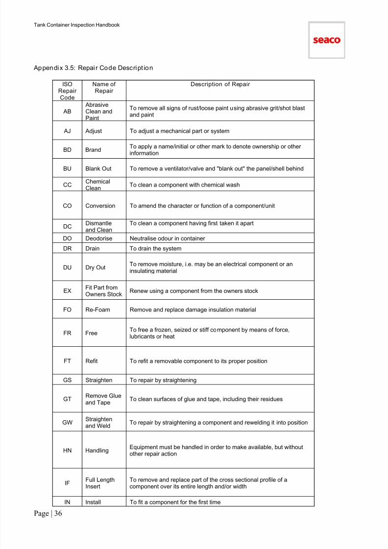
Appendix 3.5: Repai r Code Descript ion
ISORepair
Code
Name ofRepair
Description of Repair
AB AbrasiveClean andPaint
To remove all signs of rust/loose paint using abrasive grit/shot blastand paint
AJ Adjust To adjust a mechanical part or system
BD BrandTo apply a name/initial or other mark to denote ownership or otherinformation
BU Blank Out To remove a ventilator/valve and "blank out" the panel/shell behind
CCChemicalClean
To clean a component with chemical wash
CO Conversion To amend the character or function of a component/unit
DCDismantleand Clean
To clean a component having first taken it apart
DO Deodorise Neutralise odour in container
DR Drain To drain the system
DU Dry OutTo remove moisture, i.e. may be an electrical component or aninsulating material
EX Fit Part fromOwners Stock
Renew using a component from the owners stock
FO Re-Foam Remove and replace damage insulation material
FR FreeTo free a frozen, seized or stiff component by means of force,lubricants or heat
FT Refit To refit a removable component to its proper position
GS Straighten To repair by straightening
GTRemove Glueand Tape
To clean surfaces of glue and tape, including their residues
GWStraightenand Weld
To repair by straightening a component and rewelding it into position
HN HandlingEquipment must be handled in order to make available, but withoutother repair action
IF Full LengthInsert
To remove and replace part of the cross sectional profile of acomponent over its entire length and/or width
IN Install To fit a component for the first time

7/17/2019 Tank Container HandBook-2011
http://slidepdf.com/reader/full/tank-container-handbook-2011 38/90
Tank Container Inspection Handbook
Page | 37
ISORepairCode
Name ofRepair
Description of Repair
IPInspect andreport
Inspect equipment or component for proper function, damage orreason for non-operation, and re-estimate. An additional report willfollow on completion, with photographs if necessary.
IT InsertTo remove and replace part of the cross sectional profile of acomponent over part of its length and/or width. The replacementportion is butt welded to the original component
LC Lubricate To apply lubrication
MDModifications,Miscellaneous
To alter a component such that its specification is changed
MK Re-Mark To replace markings
MVRemoveMarkings
To remove unwanted labels, marks, logos, and graffiti
NANo ActionNecessary
The damage to the component is within acceptable limits and will notrequire repair
OX Overlay Cover a surface with a thin layer of the same or similar material
PA Paint To apply paint
PIPre-TripInspection
Checks before a unit leaves a location. These checks can includeboth visual and mechanical run checks of heating or glycol systems
PPPickle/Passivate
A series of chemical procedures where the surface of a component isfirst cleaned by an acidic solution, which is then neutralised by
chemicals
PRPartialRefurbishment
To remove localized corrosion/loose and repaint the surface of theequipment fully or partially
PSSurfacePreparationand Paint
To clean and prepare the surface and apply paint
PT Patch
Remove and replace a part of the cross sectional profile of acomponent, over only part of the component's length and/or width.
The patch is secured either by riveting or welding the sheet material tothe panel
7/17/2019 Tank Container HandBook-2011
http://slidepdf.com/reader/full/tank-container-handbook-2011 39/90
Tank Container Inspection Handbook
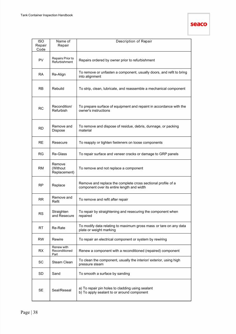
Page | 38
ISORepairCode
Name ofRepair
Description of Repair
PV Repairs Prior toRefurbishment
Repairs ordered by owner prior to refurbishment
RA Re-AlignTo remove or unfasten a component, usually doors, and refit to bringinto alignment
RB Rebuild To strip, clean, lubricate, and reassemble a mechanical component
RCRecondition/Refurbish
To prepare surface of equipment and repaint in accordance with theowner's instructions
RDRemove andDispose
To remove and dispose of residue, debris, dunnage, or packingmaterial
RE Resecure To reapply or tighten fasteners on loose components
RG Re-Glass To repair surface and veneer cracks or damage to GRP panels
RMRemove(WithoutReplacement)
To remove and not replace a component
RP ReplaceRemove and replace the complete cross sectional profile of acomponent over its entire length and width
RRRemove andRefit
To remove and refit after repair
RSStraightenand Resecure
To repair by straightening and resecuring the component whenrepaired
RT Re-RateTo modify data relating to maximum gross mass or tare on any dataplate or weight marking
RW Rewire To repair an electrical component or system by rewiring
RXRenew withReconditionedPart
Renew a component with a reconditioned (repaired) component
SC Steam CleanTo clean the component, usually the interior/ exterior, using highpressure steam
SD Sand To smooth a surface by sanding
SE Seal/Reseala) To repair pin holes to cladding using sealant
b) To apply sealant to or around component
7/17/2019 Tank Container HandBook-2011
http://slidepdf.com/reader/full/tank-container-handbook-2011 40/90
Tank Container Inspection Handbook
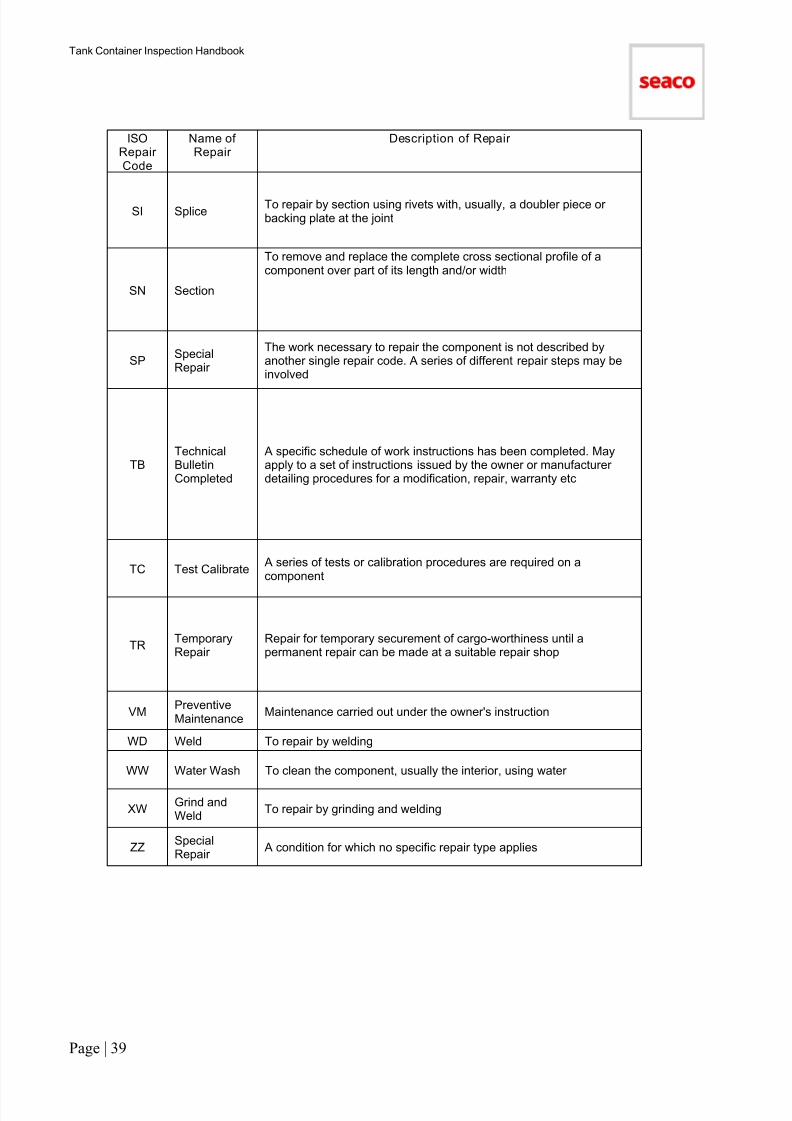
Page | 39
ISORepairCode
Name ofRepair
Description of Repair
SI SpliceTo repair by section using rivets with, usually, a doubler piece orbacking plate at the joint
SN Section
To remove and replace the complete cross sectional profile of acomponent over part of its length and/or width
SPSpecialRepair
The work necessary to repair the component is not described byanother single repair code. A series of different repair steps may beinvolved
TBTechnicalBulletinCompleted
A specific schedule of work instructions has been completed. Mayapply to a set of instructions issued by the owner or manufacturerdetailing procedures for a modification, repair, warranty etc
TC Test Calibrate A series of tests or calibration procedures are required on acomponent
TRTemporaryRepair
Repair for temporary securement of cargo-worthiness until apermanent repair can be made at a suitable repair shop
VMPreventiveMaintenance
Maintenance carried out under the owner's instruction
WD Weld To repair by welding
WW Water Wash To clean the component, usually the interior, using water
XWGrind andWeld
To repair by grinding and welding
ZZSpecialRepair
A condition for which no specific repair type applies

7/17/2019 Tank Container HandBook-2011
http://slidepdf.com/reader/full/tank-container-handbook-2011 41/90
Tank Container Inspection Handbook
Page | 40
Appendix 3.6: Cost Al locat ion
ANY ITEM
Description/RemarksDamage
Code
Cost
Al locat ion.
Repair of impact damage Various U
Replacement of lost or missing components MS U
Replacement of life expired components, damage resultingfrom inevitable exposure to normal operating conditions. e.g.hardening/deterioration of seals, discoloration of decals,electrical component not functioning and no signs of damageetc
WT O
Unacceptable improper repairs done during the most recentlease or unacceptable non standard components fitted during
the most recent lease
IR U
Unacceptable improper repairs done prior to the most recentlease or unacceptable non-standard components fitted prior tothe most recent lease
IO O
Consequential damage resulting from the Lessee's failure tocarry out a necessary repair (i.e. saturation of the insulationresulting from a failure to repair the cladding)
CD U
CLEANLINESS
Description/Remarks DamageCode Cost Al locat ion.
Cleanliness Certificate missing MS U
Normal cleaning of the tank container – interior and cargospillage on exterior
DB U
Normal cleaning of the tank container – exterior (road dirt, notcargo spillage)
WT O
Additional cleaning of the tank container due to impropercleaning before redelivery when the tank container is returnedwith a valid cleaning document
This is when the tank container is not su fficiently clean (i.e.re-cleaning of seals , gaskets, valves or blemishes/traces ofprevious cargo)
IC U
Removal of non standard decals or marks ML U
Residue of previous cargo that can only be removed by specialprocedures (These procedures can include structural repair,partial or full refurbishment, component replacement, or aspecial cleaning method)
This code should not be used for seals and gaskets
CT U

7/17/2019 Tank Container HandBook-2011
http://slidepdf.com/reader/full/tank-container-handbook-2011 42/90
Tank Container Inspection Handbook
Page | 41
Description/RemarksDamage
CodeCost
Al locat ion.
Polishing of the tank container – interior (e.g. removal of cargo
residues)
DB U
TESTING
Description/RemarksDamage
CodeCost
Al locat ion.
Periodic testing of the tank container, e.g. 2.5 and 5 year tests TR O
Leak test due to repairs on the shell etc (code leak test same asthe damage)
Various U
REFURB AND POST REFURB REPAIRS
Description/Remarks DamageCode
Cost Al locat ion.
Full refurbishment and additional work as a result of abrasiveblasting on units subject to refurbishment other than specifiedbelow
CO O
Partial refurbishment and additional work as a result of abrasiveblasting on units subject to refurbishment other than specifiedbelow
CO O
Where necessary due to cargo spillage/contamination CT U
WET/SATURATED INSULATION FOAM
Description/Remarks DamageCode Cost Al locat ion.
As a result of damage or failure of lessee to carry out a repairor seal a damaged area
ST U
As a result of old improper repairs IO O
As a result of deteriorating sealant on old repairs WT O
As a result of a wear and tear (ARD) WT O
MANUFACTURING DEFECTS
Description/RemarksDamage
CodeCost
Al locat ion.
New manufacturing defects, units less than 5 years old, (i.e. amanufacturing defect not detailed by a current technicalbulletin). This also includes post refurbishment repair work
MN O
Existing manufacturing defect (detailed by a current TTB) ME O
SEALANT
Description/RemarksDamage
CodeCost
Al locat ion.
Replacement of sealant which has failed as a result of wear andtear (ARD)
WT O
Sealant required as a result of an impact damage or improperoperation
LO U
7/17/2019 Tank Container HandBook-2011
http://slidepdf.com/reader/full/tank-container-handbook-2011 43/90
Tank Container Inspection Handbook
Page | 42
Section 4
INSPECTION PROCEDURES
7/17/2019 Tank Container HandBook-2011
http://slidepdf.com/reader/full/tank-container-handbook-2011 44/90
Tank Container Inspection Handbook
Page | 43
Section 4: Inspection Procedures
Contents of Section
Inspection Procedures Safe Inspection Procedures and Practice (45)
A. Pre Repair (Estimate Verification) (45)
B. Joint Survey (45)
C. Post Repair (46)
D. Combined Post-Repair & On-Hire (48)
E. Supplementary Estimate Verification (48)
F. On-Hire Survey (48)
G. Pre-delivery Inspection (49)
Appendix 4.1: Lessee Refuse Report (50)
INSPECTION PROCEDURES
Introduction
There are seven standard inspections that might be carried out while tank containers are in depot off-hire.Seaco will confirm the inspections required.
All inspections must be carried out by a Seaco Surveyor except for pre-delivery on-hire surveys which should becarried out by the depot's own quality control personnel.
Inspection Types and their Objectives
A. Pre Repair (Est imate Veri ficat ion):
Ensures the repair estimate conforms to Seaco requirements prior to transmittion to Seaco OperationsCentre
B. Joint-Survey: Confirms with the customer's surveyor the allocation of repair costs
C. Post Repair: Ensures the tank container has been repaired correctly and is status ‘AVLB’
D. Combined – Post Repair and On-Hire: Ensures the tank container has been repaired correctly and is status ‘AVLB’ (Additionally, provide forinspection as in F).
E. Supplementary Estimate Verifi cation: Ensures the additional work is necessary
F. On-Hire Survey: Performed prior to lease, ensuring the tank container complies with requirements. The report is posted onsurvey company web site and includes itemised report, photos and cleaning certificate
G. Pre-Delivery Inspection: Depot check prior to lease ensuring the tank container complies with requirements.

7/17/2019 Tank Container HandBook-2011
http://slidepdf.com/reader/full/tank-container-handbook-2011 45/90
Tank Container Inspection Handbook
Page | 44
A. Pre Repair (Est imate Ver if ication)
Authent icating the Repai r Es timate
This must be performed promptly after depot has completed the repair estimate.Must be performed as requested by Seaco Operations.Is not required on tank containers freemoved from manufacturer unless specified by Seaco Operations.
Note: These tank containers will require a visual exterior inspection for transit damage after freemove.
Action to be taken by the Seaco Surveyor: The Seaco Surveyor must inspect the tank container and ensure that the repair estimate is correct. The repairestimate must be completed in accordance with the instructions in Section 3. When the Seaco Surveyor issatisfied that the repair estimate for the tank container is correct he and depot representative must sign anddate the estimate.
Repair estimate checks must inc lude:
− A current, valid cleanliness certificate
− The last cargo data is correctly entered
− Damage codes entered correctly
− Only damage requiring repair is noted
− Correct method of repair is adopted
− Tank Technical Bulletin requirements met
− Repair costs (labour/materials) are correct to tariff and use the most cost effective repair method andreduced costs for combination damages
− Function testing of the electrical heating or other components has been carried out
− Statutory test requirements complied with
− An internal mapping chart completed if a problem exists on the shell interior
B. Joint Surveys (with customer’s surveyor)
The joint survey is carried out after the post-estimate inspection and must be performed using the SeacoDamage Notification.
The customer's surveyor must provide their own copy of the damage notification. All customers’ surveyors mustattend at same time.
The two surveyors must agree the material costs and labour hours as allocated or an amended allocation. Theestimate must clearly show all amendments.
The estimate must be signed and dated by both the Seaco and customer's surveyors.
The Seaco Surveyor may alter an item on the estimate by amending the damage and repair codes, descriptionand the costs.
After amendment the repair must still conform to tank inspection criteria or requirements.
All amendments must be agreed with depot.
If the customer's surveyor agrees costs, but refuses to sign the estimate, he should be warned that thesurvey is invalidated. The Seaco Surveyor must write on the estimate Costs agreed but customer'ssurveyor unwilling to sign, and sign/date it himself.
The depot must report the joint survey result and amended costs immediately to the local Seaco OperationsCentre via the reporting system.
If agreement is not reached between the surveyors then the Seaco Surveyor must immediately report to thelocal Seaco Operations Centre.

7/17/2019 Tank Container HandBook-2011
http://slidepdf.com/reader/full/tank-container-handbook-2011 46/90
Tank Container Inspection Handbook
Page | 45
Lessee Refused Costs Report
− Details of refused costs
− Colour photos of the refused items
− Reasons why costs refused
− Send report to local Seaco Operations Centre
− A copy of this form is shown at Appendix 4.1
C. Post Repair
The post repair process is used as a means for Seaco to verify that the unit has been repaired in accordancewith the estimate and meets all applicable criteria for a unit to be on-hired.
The post repair inspection procedures will be performed in depots as requested by Seaco Operations.
Post Repair Inspection
The following procedures must be followed when performing a post repair inspection.
At any time new or amended requirements or criteria may be introduced for specific tank containers or tankcontainers in general, these must be applied in addition to the procedures below during the post repairinspection.
C.1. Tank Container
The tank container being inspected must meet the specifications of a status ‘AVLB’ tank container with regard tothe inspection criteria as noted in the Tank Inspection Handbook, TTB’s and other technical requirements thatmay be in force. All repairs noted on the estimate and any damages that were not noted on the estimate mustbe fully repaired.
Additionally an internal mapping chart will be completed and photos taken of the various components noted
below in C.3.
C.2. Statutory Test Validit y
The inspector must ensure that the tank container statutory test validity is current; otherwise it must be updatedas necessary. The requirements of the statutory test are noted in the Tank Inspection Handbook.
C.3. Photos and On-Hire Report Check
Every tank container will require a number of photos to be taken during the on-hire inspection. The photos mustclearly show:1) External full side RHS / LHS view.2) External full rear end / front end/top/underside view.3) External rear/side 45 deg.
4) External front/side 45 deg.5) View of rear top compartment, containing fittings in close-up when lid open.6) View of top centre compartment containing fittings in close-up when lid open.7) View of rear bottom compartment containing fittings in close-up.8) View of all other fittings,9) Views inside vessel showing all apertures and fittings.10) Internal RHS/LHS view.11) Internal rear end / front end/top/ bottom view.
11) Data plate
An on-hire report must be completed in an approved format together with an internal mapping chart. Thecleanliness certificate shall be renewed. The report and photos must be made available on the inspectioncompany’s web site.
C.4. Cleanliness Certificate
Every tank container must enter the depot with a valid cleaning document. At the conclusion of the on-hireinspection the inspector should re-validate the existing cleanliness certificate or issue a new certificate.
7/17/2019 Tank Container HandBook-2011
http://slidepdf.com/reader/full/tank-container-handbook-2011 47/90
Tank Container Inspection Handbook
Page | 46
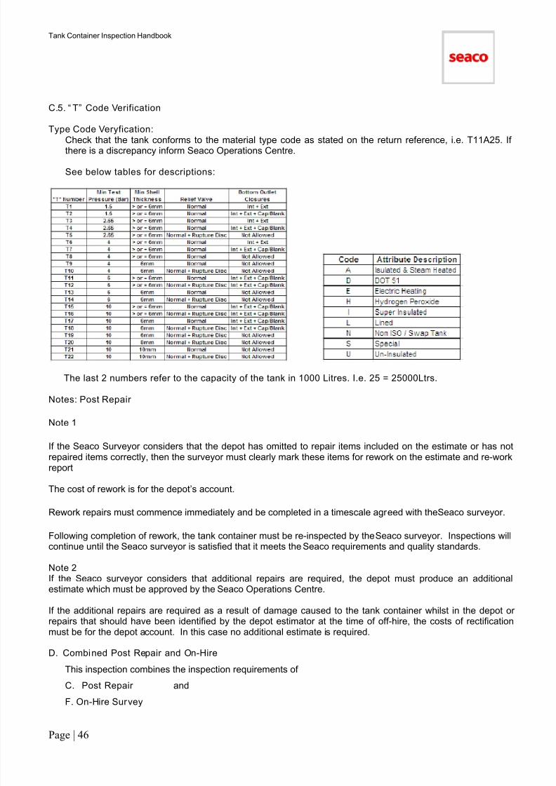
C.5. “ T” Code Verification
Type Code Veryfication:
Check that the tank conforms to the material type code as stated on the return reference, i.e. T11A25. Ifthere is a discrepancy inform Seaco Operations Centre.
See below tables for descriptions:
The last 2 numbers refer to the capacity of the tank in 1000 Litres. I.e. 25 = 25000Ltrs.
Notes: Post Repair
Note 1
If the Seaco Surveyor considers that the depot has omitted to repair items included on the estimate or has notrepaired items correctly, then the surveyor must clearly mark these items for rework on the estimate and re-workreport
The cost of rework is for the depot’s account.
Rework repairs must commence immediately and be completed in a timescale agreed with the Seaco surveyor.
Following completion of rework, the tank container must be re-inspected by the Seaco surveyor. Inspections will
continue until the Seaco surveyor is satisfied that it meets the Seaco requirements and quality standards.
Note 2If the Seaco surveyor considers that additional repairs are required, the depot must produce an additionalestimate which must be approved by the Seaco Operations Centre.
If the additional repairs are required as a result of damage caused to the tank container whilst in the depot orrepairs that should have been identified by the depot estimator at the time of off-hire, the costs of rectificationmust be for the depot account. In this case no additional estimate is required.
D. Combined Post Repair and On-Hire
This inspection combines the inspection requirements of
C. Post Repair and F. On-Hire Survey
7/17/2019 Tank Container HandBook-2011
http://slidepdf.com/reader/full/tank-container-handbook-2011 48/90
Tank Container Inspection Handbook
Page | 47
E. Supplementary Estimate Verification
The original estimate should indicate all damages requiring repair in addition to all TTB’s and maintenance work
required at the time of redelivery.
Normally the only time a supplementary estimate for extra work will be required is when a tank container hasbeen in depot for a period of time and it requires maintenance work or when there is a specific request from thelocal Seaco Operations Centre to modify the tank container or fittings.
Any supplementary estimate should be submitted as per all normal procedures. The local Seaco OperationsCentre may request a survey prior to work being authorised. Photographs to be supplied if necessary.
The survey must ensure that the work is actually necessary and that it conforms to Seaco requirements and toallocate the costs to either the depot or Seaco account.
F. On-Hire SurveyIf the customer requests an on-hire survey the procedures below must be followed in addition to the pre-delivery inspection procedures.
If the customer does not require an on-hire survey then the pre-delivery inspection carried out by the Seacosurveyor will serve to ensure that the tank container is in good working order prior to delivery to lease.
Procedure
This survey must be carried out with reference to the criteria detailed in Section 8 (Inspection Guidelines forTank Containers).
If an item is beyond the acceptable limits as specified in Section 8 the survey must cease until the requiredrepairs have been carried out.
If the customer's surveyor accepts the tank container as being in satisfactory operating condition butnevertheless refuses to sign the on-hire survey form, the Seaco representative must note in the REMARKS boxthe words ‘acceptable to customer but customer's surveyor unwilling to sign’. The Seaco representativemust also add brief comments as to the reason for the refusal. The Seaco representative must immediatelyadvise the local Seaco Operations Centre.
The Seaco surveyor must immediately inform the local Seaco Operations Centre:
− Customer’s surveyor rejects a unit as non- satisfactory and in the opinion of the Seaco surveyor the tankcontainer is in satisfactory condition.
− If the customer's surveyor requests further checks of the tank container in addition to those detailed in thishandbook.
If the customer's surveyor has their own on-hire survey report and requests the Seaco surveyor to sign it; the
Seaco surveyor must not sign it unless all the following conditions are fulfilled:
− All codes used are clearly defined on form
− All comments relating to the condition and operating serviceability of the unit are in accordance with thoseentered on the Seaco form
− The customer's surveyor also signs the Seaco form
− The customer's surveyor provides the Seaco representative with a copy of his own on-hire survey report
The Seaco form is always the official report confirming the agreement between Seaco and the customerregarding the operating condition and serviceability of the tank container. The customer's own on-hiresurvey report does NOT take precedence over Seaco 's.

7/17/2019 Tank Container HandBook-2011
http://slidepdf.com/reader/full/tank-container-handbook-2011 49/90
Tank Container Inspection Handbook
Page | 48
G. Pre-Delivery Inspection
This inspection must be carried out by the depot immediately prior to release of the tank container.
The depot prior to delivery to the customer must survey every tank container being delivered for which Seaco
has given release authorisation. In the case of special tank containers their individual requirements must bechecked.
The depot must ensure the tank container:
− Conforms to Seaco booking requirements by type, specification and last cargo
− Any special requirements detailed in the booking advice have been completed
− If it is more than 6 months since the on-hire inspection then the pre-delivery inspection mustinclude a leak check and new cleaning certificate
− Is fit for service according to Seaco’s repair requirements and quality standards, including specificrequirements for ‘special’ tank containers
− Must be fully operational according to the inspection criteria
− Interior clean and dry
− Valves closed, manlid and spill box secure
If the tank container is not repaired correctly, then it must be reworked.
− The cost of rework is for the depot's account
− Rework repairs must commence immediately and be completed in a timescale agreed with the local SeacoOperations Centre
− The unit must be re-inspected
Electrical - depot must complete a function test and retain the run test results.
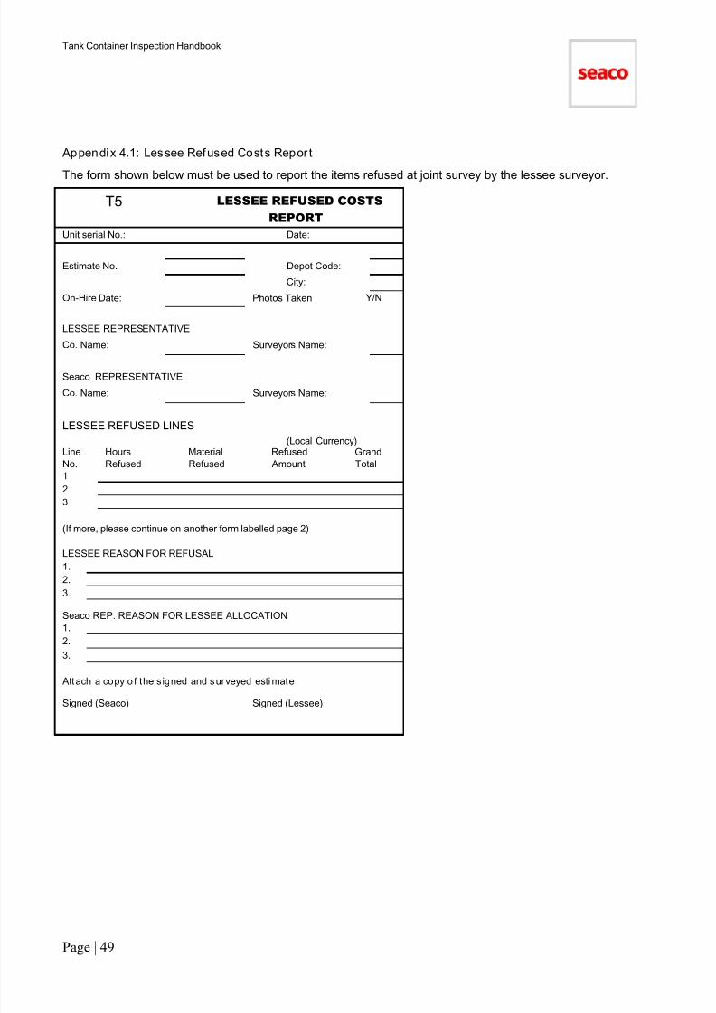
7/17/2019 Tank Container HandBook-2011
http://slidepdf.com/reader/full/tank-container-handbook-2011 50/90
Tank Container Inspection Handbook
Page | 49
Appendix 4.1: Lessee Refused Costs Repor t
The form shown below must be used to report the items refused at joint survey by the lessee surveyor.
LESSEE REFUSED COSTS
REPORT
Unit serial No.: Date:
Estimate No. Depot Code:
City:
On-Hire Date: Photos Taken Y/N
LESSEE REPRESENTATIVE
Co. Name: Surveyors Name:
Seaco REPRESENTATIVE
Co. Name: Surveyors Name:
LESSEE REFUSED LINES
(Local Currency)Line Hours Material Refused Grand
No. Refused Refused Amount Total
1
2
3
(If more, please continue on another form labelled page 2)
LESSEE REASON FOR REFUSAL
1.
2.
3.
Seaco REP. REASON FOR LESSEE ALLOCATION
1.
2.
3.
Attach a copy o f the signed and surveyed esti mate
Signed (Seaco) Signed (Lessee)
T5
7/17/2019 Tank Container HandBook-2011
http://slidepdf.com/reader/full/tank-container-handbook-2011 51/90
Tank Container Inspection Handbook
Page | 50
Section 5
IDENTIFICATION OF MANUFACTURERS' DEFECTS
AND
PROCEDURE FOR REPORTING MANUFACTURERS'DEFECTS
7/17/2019 Tank Container HandBook-2011
http://slidepdf.com/reader/full/tank-container-handbook-2011 52/90
Tank Container Inspection Handbook
Page | 51
Section 5: Identification of Manufacturers’Defects and Procedure forReporting Manufacturers’Defects
Contents of Section
Identification of Manufacturers' Defects (52)
Procedure for Reporting Manufacturers' Defects (53)
Appendix 5.1: Warranty Report forNew Defects
(55)
IDENTIFICATION OF MANUFACTURERS' DEFECTS
The inspector should be aware of the need to monitor tank container design and report potential manufacturingdefects and unsatisfactory design in addition to actual manufacturing defects.
Manufacturing defects must be identified and correctly reported on the repair estimate.
Typical defects might be those involving:
1. Fatigue Cracks
The most common fatigue cracks occur in the frame and at attachments between the frame and the tank. Alltank containers should be checked for any signs of stress related failure of either welds or parent material.
2. Weld Defects
Possible defects are porosity, lack of fusion or misalignments to welds. Defects to the frame and bearersupports are often revealed by cracks in the welds.
3. Defects Affecting ISO Dimensions
This type of defect is often identified after difficulties have been experienced in lifting a container by spreader.
Over tolerance variances in ISO dimensions are more often as a result of damage or previous improper repairrather than defects in the original manufacture. However, it may be that a design defect to the end frame hascaused misalignment.
Expansion of the insulation causing the insulation and cladding to exceed ISO tolerances is often the result ofmoisture ingress. It may be that defects to the security or water tightness of the cladding joints at manufactureare the root cause of the defect.
4. Paint and Surface Preparation
Inspectors should be alert for any signs of corrosion that do not appear to be the result of normal deteriorationor damage. Corrosion on a container of recent manufacture is a probable indication that the paint system is
defective.
The following are the most common types of paint related problems:
(i) Paint Film Detachment
The detachment of areas of the paint film in the absence of signs of sufficient impact or chemical contaminationis a sign of coating adhesion failure.
Such detachment may involve the top coat separating from the primer coat leaving the primer intact oralternatively the entire paint coating may detach leaving the bare steel substrate.
This type of failure is the result of lack of intercoat adhesion, poor metal preparation, contamination of thesubstrate or brittle paint.
(ii) Light Surface Corrosion
Light surface corrosion appearing through the paint film may indicate insufficient paint film thickness.Where the corrosion appears on the exterior of the painted stainless steel shell this is often due tocontamination by carbon steel particles at manufacture prior to painting.

7/17/2019 Tank Container HandBook-2011
http://slidepdf.com/reader/full/tank-container-handbook-2011 53/90
Tank Container Inspection Handbook
Page | 52
(iii) Corrosion Blisters
This is the most serious type of corrosion and can cause much damage to the steel unless promptly treated.
Corrosion blisters form below the paint film and result in deep seated areas of rust and rapid decomposition ofthe steel.
In the early stages the blisters appear as small bumps beneath the paint film which at this stage is stillundamaged. As the steel starts to break down the size of the blisters increase until they break through the paintfilm. By this stage the corrosion process is well advanced and will have already significantly reduced the steelthickness.
(iv) Electrolytic Corrosion
Corrosion blisters described in (iii) above can occur around data plates and other metal components attached tothe container. This may be a result of using incompatible materials, usually the fasteners.
Corrosion of aluminium fasteners and aluminium cladding might also be a result of electrolytic corrosion.
5. Electrical FailureFailure of items such as printed circuit boards, thermostat contacts and heating elements may be due to amanufacturers’ design defect.
The common cause of defects to the above items is moisture ingress through joints in cladding and controlboxes as a result of defects at manufacture. However, previous improper repairs or failure to carry out repairsto damage on a timely basis must be investigated.
PROCEDURE FOR REPORTING MANUFACTURERS' DEFECTS
Potential Manufacturing Defects and Unsatisfactory Design
Depots and inspectors should report to Seaco any defect or design defects that may be present on a tank
container:
a) Design difficult to repairb) Design frequently damaged, orc) Vulnerable to damaged) Early deterioration, which although not a defect may become one
The procedure covers units of all equipment types. It applies both to new manufacturers' defects and alsoexisting manufacturers' defects.
For ease of reference the definition of new and existing manufacturers' defects is:
New Manufacturers' Defect
Any failure discovered on a unit which is less than 5 years old and which cannot be attributed to wear and tear,and which has not been identified in the Tank Fleet Survey by a TTB.
The age of the unit must be determined by reference to the Tank Fleet Survey, not by reference to the dataplate on the unit.
Existing Manufacturers' Defect Any failure which has been confirmed by Seaco to be a manufacturers' defect, and which has been eitheridentified in the Tank Fleet Survey or covered by a TTB or other formal circular instruction issued by Seaco.

7/17/2019 Tank Container HandBook-2011
http://slidepdf.com/reader/full/tank-container-handbook-2011 54/90
Tank Container Inspection Handbook
Page | 53
PROCEDURE
1. New Manufacturers ’ Defects (New MD)
When a New MD is identified, the depot must without delay send to the local Seaco Operations Centre:
− A copy of the full printed Repair Estimate
− Clear photos illustrating the New MD. Each photo must be marked with the unit serial number, date ofphoto, location, name of inspector, returning lessee.
− A completed inspection report, using the standard Seaco Warranty Report form. No other reporting formatshould be use
An example of the Warranty Report is shown as Appendix 5.1.
Note: Up to five units may be entered on one form providing all the units are of the same manufacturer anddisplay similar defects.
2. Existing Manufacturer’s Defects(Existing MD)
For each unit on which an Existing MD is recorded, the following must be sent by the depot to the local SeacoOperations Centre:
− A copy of the full printed repair estimate
− Clear photos illustrating the MD (subject to exceptions listed below). Each photo must be marked with thesame data as listed above for New MD's. In addition the TTB reference number must be shown.
Note: Photos are not required for all existing MD's. TTB's will state whether or not photos are required (Inmost cases photos will be required for an initial period and then the requirement will be withdrawn).
Photos should clearly indicate the potential or actual problem. Photographs sent as a .pdf file should be namedto clearly state: -
Tank container serial number Date Depot or location where photo taken TTB number if applicable
. If photographs are sent in hard copy then writen On the rear of the photo the following must be clearly noted:
Tank container serial number Date Depot or location where photo taken TTB number if applicable
No Warranty Report or other inspection report is required for Existing MD's unless otherwise stated on theTTB.
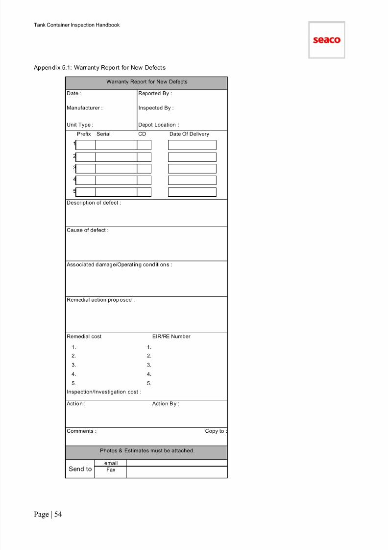
7/17/2019 Tank Container HandBook-2011
http://slidepdf.com/reader/full/tank-container-handbook-2011 55/90
Tank Container Inspection Handbook
Page | 54
Appendix 5.1: Warranty Report for New Defects
Warranty Report for New Defects Date : Reported By :
Manufacturer : Inspected By :
Unit Type : Depot Location :
Prefix Serial CD Date Of Delivery
1
2
3
4
5
Description of defect :
Cause of defect :
Associated damage/Operat ing conditi ons :
Remedial action prop osed :
Remedial cost EIR/RE Number
1. 1.
2. 2.
3. 3.
4. 4.
5. 5.Inspection/Investigation cost :
Act ion : Act ion By :
Comments : Copy to :
Photos & Estimates must be attached.
Send toemail
Fax
7/17/2019 Tank Container HandBook-2011
http://slidepdf.com/reader/full/tank-container-handbook-2011 56/90
Tank Container Inspection Handbook
Page | 55
Section 6
IDENTIFICATION OF FREQUENT MISUSE OF TANKCONTAINERS

7/17/2019 Tank Container HandBook-2011
http://slidepdf.com/reader/full/tank-container-handbook-2011 57/90
Tank Container Inspection Handbook
Page | 56
Section 6: IDENTIFICATION OF FREQUENT MISUSE OF TANK CONTAINERS
Contents of Section
A container may be deemed to have been misused if it has been subjected to any of the following conditionswhich have resulted in damage:
− Used in excess of the designed working pressure (overpressure), or without ventilation (implosion) orexcess heat (over-heating)Handled by any means other than those specified in ISO document DIS 3874.Top side lift equipment (unladen tank containers only) must be of the full frame type. Handling by forkliftequipment is not permitted for tank containers
− Transported a cargo that has caused damage by reaction between the cargo and the container
− Transported by any vehicle or vessel which is not suitable for the carriage of containers
− Used when the operating or assembly instructions have not been followed or when necessary componentsare not present or correctly fitted
Complete the repair estimate as normal and immediately report misuse to the local Seaco Operations Centre.Containers subjected to misuse may be identified if they display characteristics such as:
Used in excess of designed working pressure
− Splits or distortion to steam tubes or shell. Excess steam pressure will additionally result in excesstemperature causing the insulation or exterior shell protective coating to char. Implosion will result in the tankshell or other components bowing inwards. It is caused by failure to vent the tank container after cleaning orwhilst discharging
Handled by any means other than specified in ISO document DIS 3874. Top side lif t equipment (unladentank containers only) must be of the full frame type
− Distortion of the top third of tank shell (chains too short)− Distortion of the manway area due to lifting by use of a yoke in the manway opening
− End frames leaning in towards the interior of the unit (chains too short)
− Permanent twist in the container about a diagonal horizontal axis (lifted by chains from two diagonallyopposite corner castings)
− Distortion to the underside shell, steam tubes or cladding (lifting by forks)
− Distortion to the side shell or cladding due to top side lifting without adequate support to the bottom side
− Distortion of the tank support bearers or movement of the tank within the frame due to the unit having beendropped
Transported a cargo that has caused damage to the tank container by reaction between the cargo andthe container
− General corrosion and staining
− Corrosion pitting− Stress corrosion cracking
− Damage to paint coating or cladding caused by spillage or storage in a chemical environment
Transported by any vehicle or vessel which is no t suitable for the carriage of containers
− Abrasion or damage caused by the use of makeshift lashing
Used when the operating or assembly instructions have not been followed or when necessarycomponents are not present or correctly fitted
− Implosion of the tank shell due to inadequate venting on discharge
− Implosion of the tank shell due to inadequate venting after hot washing
− Splits in the insulation and cladding due to operation of the tank container in excess of the maximum cargo
temperatures or charring of the insulation or shell exterior coating.− Damage resulting from disregarding assembly or security instructions
− Damaged valves and fittings due to improper tools (incorrect size wrench)
7/17/2019 Tank Container HandBook-2011
http://slidepdf.com/reader/full/tank-container-handbook-2011 58/90
Tank Container Inspection Handbook
Page | 57
− Damage to manway lid and compartment due to failure to secure when transporting or stacking the tankcontainer
− Burnt electrical components due to incorrect voltage supply
− Damage to electrical components due to failure to secure control box doors
7/17/2019 Tank Container HandBook-2011
http://slidepdf.com/reader/full/tank-container-handbook-2011 59/90
Tank Container Inspection Handbook
Page | 58
Section 7
IMPROPER REPAIRS
7/17/2019 Tank Container HandBook-2011
http://slidepdf.com/reader/full/tank-container-handbook-2011 60/90
Tank Container Inspection Handbook
Page | 59
Section 7: Improper Repairs
IMPROPER REPAIRS
An improper repair is any repair not performed where any one of the following defects is present:
- The repair has not been performed in accordance with ITCO/ACC recommended repair methods.
- The repair is of a quality or condition which could still be defined as damage according to the ITCO/ACCinspection criteria and Seaco guidelines.
- The repair has an adverse affect on the original ISO dimensions of the tank container.
- The repair affects the structural integrity or cubic capacity of the tank container.
- The repair compromises the safety of the tank container.
- The repair is not in compliance with the applicable regulations.
- Use of incorrect materials.
- Sub-standard preparation or painting.
- Poor quality welding or workmanship.
Not all improper repairs, as defined, need to be reworked.
A distinction has to be drawn between repairs in progress and therefore controllable and repairs already inexistence on a container, which is being considered for rectification.
All repairs carried out under the control of Seaco must be performed in accordance with ITCO/ACC repairprocedures. Any repair performed in a Seaco depot which does not meet the ITCO/ACC repair criteria shouldbe rejected and the container considered still damaged and unavailable for lease until the repair has been madegood in accordance with ITCO/ACC repair procedures.
Existing repairs which do not strictly meet Seaco requirements can be considered acceptable if they meet thefollowing requirements:
- The repair has been carried out in a competent manner using correct materials and a good standard ofworkmanship.
- Repairs to cladding which although unsightly, are watertight.
- The container conforms to CSC criteria.
- Repairs which may not have been properly cleaned and painted and are showing signs of superficialcorrosion.
NOTE: - Seaco must be informed when the inspector has any doubt about the integrity of an improperacceptable repair.
7/17/2019 Tank Container HandBook-2011
http://slidepdf.com/reader/full/tank-container-handbook-2011 61/90
Tank Container Inspection Handbook
Page | 60
Section 8
INSPECTION GUIDELINES FOR TANK CONTAINERS
ACCEPTABLE CONTAINER CONDITION
(ACC)
7/17/2019 Tank Container HandBook-2011
http://slidepdf.com/reader/full/tank-container-handbook-2011 62/90
Tank Container Inspection Handbook
Page | 61
Section 8: Inspection Guidelines for TankContainers
Contents of Section
Introduction (63)
1. Cleanliness (64)
2. Frame (65)
3. Walkway Assembly (68)
4. Paintwork (68)
5. Insulation and Cladding (69)
6. Manway Assembly (71)
7. Safety Valves (72)8. Top Valves (74)
9. Shell (77)
10. Bottom Valves (77)
11. Heating (81)
12. Miscellaneous
a) Decals and Data Plates (82)
b) Document Holder (82)
c) Spill Box & Compartments (83)
d) Earth (Ground) Lug (83)
13. Test (84)
7/17/2019 Tank Container HandBook-2011
http://slidepdf.com/reader/full/tank-container-handbook-2011 63/90
Tank Container Inspection Handbook
Page | 62
INTRODUCTION
ACCEPTABLE AND NOT ACCEPTABLE DAMAGE
The inspection guide which follows lists the component parts of a tank container and defines the tank Acceptable Container Condition (ACC) criteria for:
− Not Acceptable Damage/Condition
− Acceptable Damage/Condition
NOT ACCEPTABLE DAMAGE/CONDITION is damage that affects the safety, structural integrity, cargo-carrying capacity or the ISO dimensions, integrity of the tank container or not in compliance with the applicableregulations.
THIS TYPE OF DAMAGE MUST BE REPAIRED
ACCEPTABLE DAMAGE/CONDITION is minor damage or fair wear and tear which does not significantly affectany of the above conditions and therefore:
NO REPAIR IS REQUIRED.
DO NOT OPERATE VALVES/FITTINGS OR ENTER ANY TANK CONTAINER WHICH DOES NOT POSSESS A VALID CLEANLINESS CERTIFICATE AND VALID ENTRY CERTIFICATE.
OBSERVE THE SAFE INSPECTION PROCEDURES AND PRACTICE AS DETAILED IN SECTION 1 OFTHIS HANDBOOK AND ALL REGIONAL HEALTH AND SAFETY REQUIREMENTS.
7/17/2019 Tank Container HandBook-2011
http://slidepdf.com/reader/full/tank-container-handbook-2011 64/90
Tank Container Inspection Handbook
Page | 63
1. CLEANLINESS
a) INTERIOR
Not Acceptable Damage/Condition
− Previous cargo, contamination or odour
− Discolouration, product residue or transferable stain which can be removed by manual application of aplastic abrasive pad and/or solvent
− Corrosion, pitting, grinding or gouges
− Missing or improper cleanliness certificate
Acceptab le Damage/Cond it ion
− Abrasions or scratches to finer than 120 grit polish equivalent
− Discoloration which cannot be removed by plastic abrasive pad or dull appearance
An Internal Shell Condition Chart must be completed for all interior shell defects. See Section 3 for details.
Note: Tank containers without a cleaning document must be considered unsafe and should not be inspected.
A cleanliness document is required for all tank containers prior to redelivery to depot for lease termination (off-
hire).
If the cleanliness document is not a cleanliness certificate the tank container may be off-hired but a cleanlinesscertificate is required and should be added to the off-hire estimate and issued by a qualified person.
Note: Where stains are present, clean a test area at the time of estimate preparation to both determine the costand ensure stains do not conceal corrosion pitting.
If heavily stained tank containers are redelivered, contact the local Seaco Operations Centreimmediately, to arrange re-cleaning prio r to of f-hire.
b) EXTERIOR
Not Acceptable Damage/Condition
− Previous cargo, contamination
− Oil, grease deposits− Road dirt reducing legibility of tank container markings
− Significant and unsightly dust and dirt
Acceptab le Damage/Cond it ion
− Road dirt, minor dust and dirt
Note: The valve and spill boxes must be clean and free of cargo spillage. Check areas of overspill for damageto paint and cladding and inspect drain tubes for blockage.
c) FOREIGN MARKINGS
Not Acceptable Damage/Condition
− Hazard warning labels or cargo labels
− Non-standard labels or misleading marks− Remnants of labels
− Insecure or unserviceable label holders
− Customer logo or markings
Acceptab le Damage/Cond it ion
− Serviceable label holders
− Minor glue residue
Note:
− Non-standard or damaged label holders should not be replaced. Remove and make good the area
− If a customer logo has been fitted over or in place of the Seaco or owners’ logo, the customer logo shouldbe removed. It is not necessary to renew the Seaco or owners’ logo (see part 12 of this section)

7/17/2019 Tank Container HandBook-2011
http://slidepdf.com/reader/full/tank-container-handbook-2011 65/90
Tank Container Inspection Handbook
Page | 64
2. FRAME
a) CORNER POSTS
Not Acceptable Damage/Condition
− Cuts, holes, gouges or splits
− Cracks or splits in welds or parent metal.
− Improper repairs
− Dents or distortions of a formed edge or face greater than 15mm irrespective of length of deformation
− Dents greater than 10mm and less than 15 mm in depth in excess of two per post
− Dents greater than 10mm exceeding 300mm in length
− Twisted or bent or over-plated beyond ISO.
− Corrosion affecting the structural strength of the member
Acceptable Damage/Condi tion
− Dents or distortions not exceeding 15mm in depth except as qualified aboveNote: The Seaco preferred corner post insert shape has angled ends. However existing inserts with squareends are acceptable if all other criteria are satisfied.
A maximum of two structurally sound inserts are allowed to each post.
An insert may extend to include a maximum of two formed edges.
Not Acceptable
2.1i a. insert through 3 formed edges
2.1i b. less than 300mm from casting
2.1ii less than 150mm between inserts
2.1iii overlapping inserts
2.1iv more than two inserts per post

7/17/2019 Tank Container HandBook-2011
http://slidepdf.com/reader/full/tank-container-handbook-2011 66/90
Tank Container Inspection Handbook
Page | 65
Acceptab le Damage
2.2i a. minimum distance between inserts is 150mm
2.2i b. minimum size insert is 150mm
2.2ii minimum insert at post ends is 300mm
2.2iii a full-length insert is allowed
2.2iv two inserts may have a common weld
b) TOP AND BOTTOM SIDE AND END RAILS
Not Acceptable Damage/Condit ion
− Cuts, holes, gouges or splits
− Cracks in welds or parent metal
− Improper repairs
− Dents or distortions greater than 25mm
− Distortion reducing clearance preventing operation of the discharge valve
− Twisted bent outwards beyond the limits of the ISO corner dimensions
− Severe corrosion
− Loose or missing fasteners
Acceptab le Damage/Cond it ion
− Dents or distortions not exceeding 25mm
− Dents in bottom face of bottom rails which do not affect any formed edge
Note: If the damage cannot be straightened and it is necessary to repair either by an over-plate, insert or asection then the following criteria will apply when assessing the type and extent of repair required.
− The minimum permissible length of an over-plate, insert or section repair is 150mm; no maximum limit.
− No insert or section may finish within 300mm of the corner fitting weld or within 50mm of an existing verticalweld.
7/17/2019 Tank Container HandBook-2011
http://slidepdf.com/reader/full/tank-container-handbook-2011 67/90
Tank Container Inspection Handbook
Page | 66
− If the planned insert or section will end within these areas then the repairs should be extended to the cornerfitting or the existing weld.
− Over-plating is restricted to the top, bottom and inside faces of the rail where the formed edge is free ofdamage.
c) ANCILLARY BRACING
Not Acceptable Damage/Condition
− Cuts, holes, gouges or splits
− Cracks in welds or parent metal
− Improper repairs
− Dents or distortions greater than 25mm
− Twisted bent outwards beyond the limits of the ISO corner dimensions
− Severe corrosion
− Loose or missing fasteners
Acceptab le Damage/Cond it ion
− Dents and distortions less than 25mmd) TANK BEARER SUPPORTS AND
LOAD TRANSFER AREAS (LTA)
Not Acceptable Damage/Condition
− Cuts, holes, gouges or splits
− Cracks in welds or parent metal
− Improper repairs
− Dents of a formed edge greater than 13mm
− Dents or distortion of the face greater than 20mm
− Severe corrosion
− Twisted bent outwards beyond the limits of the ISO corner dimensions
− Loose or missing fasteners Acceptab le Damage/Cond it ion
− Dents not exceeding 13mm/20mm in depth as qualified above
Note: In all cases of damage to tank bearer supports the tank shell must also be inspected for damage.
In all cases of severe corrosion to the tank bearer supports the section of the bearer attached to the shell belowthe insulation must be checked for structural integrity. This may require local removal of insulation.The repair criteria is detailed in 2b) above except that over-plating is not permitted
e) STACKING SUPPORTS/MISS STACKING PLATES
Not Acceptable Damage/Condition
− Cuts, holes, gouges or splits
− Cracks in welds or parent metal
− Improper repairs
− Dents or distortions greater than 25mm
− Twisted bent outwards beyond the limits of the ISO corner dimensions
− Severe corrosion
Acceptable Damage/Condi tion
− Dents and distortions less than 25mm

7/17/2019 Tank Container HandBook-2011
http://slidepdf.com/reader/full/tank-container-handbook-2011 68/90
Tank Container Inspection Handbook
Page | 67
f) ISO DIMENSIONS (FRAME)
Not Acceptable Damage/Condition
i) Diagonals:
− Any damage which affects the ISO required diagonal measurements between corner fitting apertures
Note: The maximum permitted difference in distance between centres of apertures of diagonally oppositecorner fittings are:
20' container: 13mm All end frames: 10mm
ii) Frame – Top/Underside/Side/End:
− Any dent, bend or bow beyond the limits of the ISO corner dimensions
iii) Cladding:
− Any dent, bend or bow beyond the limits of the ISO corner dimensions
3. WALKWAY AND LADDER ASSEMBLY
Not Acceptable Damage/Condition
− Insecure
− Cuts, holes, splits, sharp edges or dents affecting safety
− Distortions greater than 50mm
− Dents greater than 25mm
− Any dent, bend or bow beyond the limits of the ISO corner dimensions
− Missing or loose fasteners or electrolytic barriers Acceptab le Damage/Cond it ion
− Distortions smaller than 50mm measured over not less than 1 m length and not affecting safety
− Dents up to 25mm and not affecting safety
− Cuts not affecting safety
4. PAINTWORK
Not Acceptable Damage/Condition
− Paint removed by spillage of cargo
− Paint removed by improper handling
− Corrosion or paint abrasion equal to, or more severe than, Euro Standard RE 4
Acceptab le Damage/Cond it ion
− Superficial Corrosion
− Light discoloration
− Light scuffs and scratches
Note: Paint damage and resulting corrosion must be repaired as part of routine maintenance. See below for areference on Euro Rusting Standard.
Re: Euro Standard Rusting
Photos show approx amount of rust present at each degree of rusting. Only applies to visible rust, i.e. rust
which has broken paint film.

7/17/2019 Tank Container HandBook-2011
http://slidepdf.com/reader/full/tank-container-handbook-2011 69/90
Tank Container Inspection Handbook
Page | 68
RE 3
1%
RE 4
3%
RE 5
8 %
RE 0 0.00% RE 5 8 %
RE 1 0.05% RE 6 15 - 20 %
RE 2 0.5% RE 7 40- 50 %
RE 3 1% RE 8 75 - 85 %
RE 4 3% RE 9 95%
5. INSULATION AND CLADDING
a) INSULATION
Not Acceptable Damage/Condition
− Missing insulation material
− Saturated by water or cargo
− Improper repairs
− Deterioration by heat (burnt or baked)
b) CLADDING
Not Acceptable Damage/Condition
− Cuts, holes, crack or splits penetrating the cladding thickness and allowing moisture ingress
− Gaps at cladding joints allowing moisture ingress
− Deterioration by heat (burnt or baked)
− Insecure cladding or retaining straps
− Surface damage or staining of cladding due to cargo contamination
− Corrosion or pitting allowing moisture ingress
− Improper Repairs
− Distorted outwards beyond the limits of ISO corner fittings
− Dents greater than 25mm
− Hammered surface (improper repair)

7/17/2019 Tank Container HandBook-2011
http://slidepdf.com/reader/full/tank-container-handbook-2011 70/90
Tank Container Inspection Handbook
Page | 69
Acceptab le Damage/Cond it ion
− Distortion not affecting security nor allowing moisture ingress except as stated above
− Abrasion
− Full belly GRP patch on existing aluminium cladding
Note: In all cases of damage to the cladding, the tank shell, heating tubes and electrical components must alsobe checked.
Note: The following criteria will apply when assessing the type and extent of repair required:
− Use overlay riveted patches as the standard repair
− Minimum patch size 150mm x 150mm
− Minimum thickness – GRP 2mm
− Minimum thickness – Alum Alloy 0.9mm (18 s.w.g.)
− Materials used should match original.
− Use overlay fibre glass tissue as the standard repair to formed GRP surfaces where riveted patches areimpractical
− Infill repairs should be used for holes less than 25mm to FRP/GRP
− Extend patches to the retainer strap where the patch is within 30 cm of the strap or if the patch requiressupport from the strap
− Care must be taken to ensure that drills or rivets do not damage the shell, steam tubes or electricalcomponents beneath the cladding
Multiple patches on panel
If the number of repairs or patches either present or required as part of the repair, distracts significantly fromthe aesthetic appearance of the tank container, then that section or panel must be replaced to achieve a moreaesthetic appearance to the tank container.
A number of small patches (multiple patches in the same area) can be repaired/replaced with a larger single
patch or a renewed panel in order to achieve a more aesthetic result. The patch material to be the same asoriginal material as possible.
Cladding Patch Repair
Section through patch
7/17/2019 Tank Container HandBook-2011
http://slidepdf.com/reader/full/tank-container-handbook-2011 71/90
Tank Container Inspection Handbook
Page | 70
6. MANWAY ASSEMBLY
a) MANLID AND SWINGBOLT ASSEMBLIES
Not Acceptable Damage/Condition
− Leaks
− Missing, insecure, seized or non-operational parts
− Dents or distortion greater than 6mm or affecting proper sealing of the manlid
− Cracks
− Missing customs sealing ring
− Pitting, corrosion or contamination
− Improper repairs
Acceptab le Damage/Cond it ion
− Non-standard hand nuts and pivot pins that are of similar design and material e.g. bronze or stainless steel
Note: Bolted manlids. All studs shall extend the full length into the flange and through the nut protruding a
minimum of one thread. Bolts shall extend the full length through the nut protruding a minimum one thread.Washers shall be fitted. Fixings to be tightened to the recommended torque
b) MANLID SEAL
Not Acceptable Damage/Condition
− Cuts, cracks or distortion affecting sealing
− Contamination
− Square butt joints and/or joints not properly sealed
− Missing or insecure
Acceptab le Damage/Cond it ion
−
Minor surface degradation (perish, ozone or chemical), which does not contain contamination and does notaffect sealingNote: Seals may be cleaned and re-used or cleaned and "turned" to use both sides.
See Page 132 for details of standard seals and gaskets.
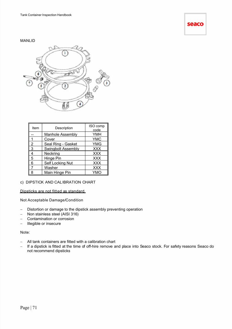
7/17/2019 Tank Container HandBook-2011
http://slidepdf.com/reader/full/tank-container-handbook-2011 72/90
Tank Container Inspection Handbook
Page | 71
MANLID
Item DescriptionISO comp
code
-- Manhole Assembly YMH
1 Cover YMC
2 Seal Ring - Gasket YMG
3 Swingbolt Assembly XXX
4 Neckring XXX
5 Hinge Pin XXX
6 Self Locking Nut XXX
7 Washer XXX
8 Main Hinge Pin YMO
c) DIPSTICK AND CALIBRATION CHART
Dipsticks are not fitt ed as standard.
Not Acceptable Damage/Condition
− Distortion or damage to the dipstick assembly preventing operation
− Non stainless steel (AISI 316)
− Contamination or corrosion
− Illegible or insecure
Note:
− All tank containers are fitted with a calibration chart
− If a dipstick is fitted at the time of off-hire remove and place into Seaco stock. For safety reasons Seaco donot recommend dipsticks
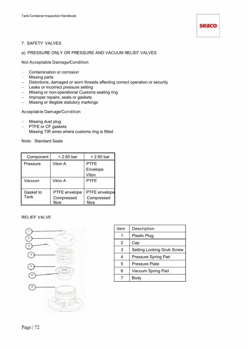
7/17/2019 Tank Container HandBook-2011
http://slidepdf.com/reader/full/tank-container-handbook-2011 73/90
Tank Container Inspection Handbook
Page | 72
7. SAFETY VALVES
a) PRESSURE ONLY OR PRESSURE AND VACUUM RELIEF VALVES
Not Acceptable Damage/Condition
− Contamination or corrosion
− Missing parts
− Distortions, damaged or worn threads affecting correct operation or security
− Leaks or incorrect pressure setting
− Missing or non-operational Customs sealing ring
− Improper repairs, seals or gaskets
− Missing or illegible statutory markings
Acceptab le Damage/Condi tion
−
Missing dust plug− PTFE or CF gaskets
− Missing TIR wires where customs ring is fitted
Note: Standard Seals
Component < 2.65 bar > 2.65 bar
Pressure Viton A PTFE
Envelope
Viton
Vacuum Viton A PTFE
Gasket toTank
PTFE envelope
Compressedfibre
PTFE envelope
Compressedfibre
RELIEF VALVE
Item Description
1 Plastic Plug
2 Cap
3 Setting Locking Grub Screw
4 Pressure Spring Pair
5 Pressure Plate
6 Vacuum Spring Pad
7 Body

7/17/2019 Tank Container HandBook-2011
http://slidepdf.com/reader/full/tank-container-handbook-2011 74/90
Tank Container Inspection Handbook
Page | 73
b) FLAME ARRESTOR GAUZE (fitted only to pressure and vacuum valves)
Not Acceptable Damage/Condition
− Missing parts (only if originally fitted)
− Damage or distortion affecting proper operation− Contamination
Note: Flame arrestors are not fitted to pressure only valves or to non-hazardous (non-regulated) tankcontainers.
c) BURSTING (RUPTURE) DISC ASSEMBLIES (where fi tted)
Not Acceptable Damage/Condition
− Leaks or incorrect pressure rating
− Contamination or corrosion
− Broken disc
− Improper parts, repairs, seals or gaskets
− Damaged pressure gauge affecting correct operation
− Missing tell tale/pressure gauge/manometer
Note: Bursting/Rupture discs and tell tale gauges are fitted in accordance to regulations to tank types to T10 /T14 / T20 / T22.
Some tank containers have screwed bursting disc flange assemblies fitted in series with relief valve as provisionfor retro-fitting of bursting discs if required. Where busting discs flange assemblies are in good condition theyshould remain on the tank.
A damaged disc must be removed and replaced only if it is a tank type where the bursting disc is standardrequirement.
8. TOP VALVES
a) AIRLINE (VAPOUR) VALVE
Not Acceptable Damage/Condit ion
− Leaks
− Contamination or corrosion
− Damage or distortion of valve or screwed fittings affecting correct operation
− Incompatible material i.e. non-stainless steel
− Defective pressure gauge
− Missing (or damaged) outlet cap or seal or retaining wire
− Improper repairs, seals or gaskets
− Missing or non-operational Customs sealing ring
− Missing or non-operational parts
Acceptable Damage/Cond it ion
− PTFE cap seals
− Caps of non-corrodible material
Note:
− Gauges (manometer) are not fitted as standard but should not be removed (and aperture plugged) unlessdefective
− Standard seals and gaskets, see below
− Studs shall extend the full length into the flange and through the nut protruding a minimum of one thread.Bolts shall extend the full length through the nut protruding a minimum one thread. Washers shall be fitted.Fixings to be tightened to the recommended torque. This applies to all stud/bolted valves and fittings

7/17/2019 Tank Container HandBook-2011
http://slidepdf.com/reader/full/tank-container-handbook-2011 75/90
Tank Container Inspection Handbook
Page | 74
b) TOP OUTLET VALVE (where fit ted)
Not Acceptable Damage/Condition
− Leaks
− Contamination or corrosion
− Damage or distortion affecting correct operation or sealing
− Missing or defective parts
− Improper repairs, seals or gaskets
− Incompatible material i.e. non-stainless steel
− Non standard parts
− Missing Customs sealing ring
− Damaged seals affecting proper sealing
Note: Provision is made for top outlet valves but the top valve is not fitted, as standard, to tank containers withbottom outlets. Where valve is fitted do not remove. The aperture (when a valve not fitted) must be fitted with abolted blank plate.
c) Siphon Pipe (Dip Pipe)
Note: Top outlet only tank containers must be fitted with siphon pipe.
Not Acceptable Damage/Condit ion
− Contamination or corrosion
− Incompatible material i.e. non-stainless steel
− Damage or distortion affecting correct operation or sealing
− Missing or non-operational parts
− Note: Gap (at bottom) of 80mm bore siphon between approx 15mm to 25mm)
d) TOP OUTLET BLANK
Not Acceptable Damage/Condition
− Leaks
− Contamination or corrosion
− Damage or distortion affecting correct operation or sealing
− Missing or defective parts
− Improper repairs, seals or gaskets
− Non stainless steel (300 series)
− Non-standard parts
− Missing Customs sealing point.

7/17/2019 Tank Container HandBook-2011
http://slidepdf.com/reader/full/tank-container-handbook-2011 76/90
Tank Container Inspection Handbook
Page | 75
TOP DISCHARGE ITEM DESCRIPTION
1 Pull Ring2 Handle Lever
3 Handle (LH)
4 Spring
5 Handle Location Pin
6 M6 x 16 Screw
7 Retaining Washer
8 M8 x 20 Capscrew (2)
9 M8 Spring Washer (2)
10Stuffing Clamp Flange C\WTIR
11 PTFE Bush
12 PTFE 'O' Ring (2)
13 Viton 'O' Ring
14 Spindle
15 Spindle Seat
16 Body
17M8 Nut (2)
M8 Spring Washer (2)
18 Closure Plate
19 PTFE Lower Spindle Bush
20 PTFE 'O' Ring
21 PTFE 'O' Ring
22 Lower Spindle
23 PTFE Seal
24 Seal Clamp & Nitrile 'O' Ring
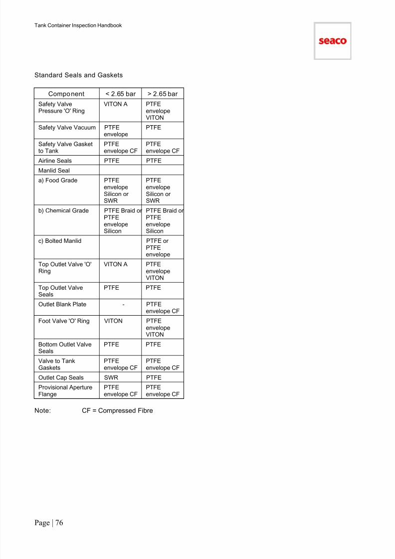
7/17/2019 Tank Container HandBook-2011
http://slidepdf.com/reader/full/tank-container-handbook-2011 77/90
Tank Container Inspection Handbook
Page | 76
Standard Seals and Gaskets
Component < 2.65 bar > 2.65 bar
Safety ValvePressure 'O' Ring
VITON A PTFEenvelopeVITON
Safety Valve Vacuum PTFEenvelope
PTFE
Safety Valve Gasketto Tank
PTFEenvelope CF
PTFEenvelope CF
Airline Seals PTFE PTFE
Manlid Seal
a) Food Grade PTFEenvelope
Silicon orSWR
PTFEenvelope
Silicon orSWR
b) Chemical Grade PTFE Braid orPTFEenvelopeSilicon
PTFE Braid orPTFEenvelopeSilicon
c) Bolted Manlid PTFE orPTFEenvelope
Top Outlet Valve 'O'Ring
VITON A PTFEenvelopeVITON
Top Outlet Valve
Seals
PTFE PTFE
Outlet Blank Plate - PTFEenvelope CF
Foot Valve 'O' Ring VITON PTFEenvelopeVITON
Bottom Outlet ValveSeals
PTFE PTFE
Valve to TankGaskets
PTFEenvelope CF
PTFEenvelope CF
Outlet Cap Seals SWR PTFE
Provisional ApertureFlange
PTFEenvelope CF
PTFEenvelope CF
Note: CF = Compressed Fibre
7/17/2019 Tank Container HandBook-2011
http://slidepdf.com/reader/full/tank-container-handbook-2011 78/90
Tank Container Inspection Handbook
Page | 77
9. Pressure Vessel (SHELL)
Not Acceptable Damage/Condition
− Leaks
− Cuts, cracks
− Defects to welds or parent materials
− Gouges, scratches or badly executed grinding (erratic pattern) deeper than 0.1mm
− Excessive grinding or other metal depletion which reduces the shell thickness to less than the minimum
− Grinding coarser than 120 grit, and excessive grinding scars/uneven pattern
− Corrosion or pitting which reduces the shell thickness below the required minimum corrosion allowanceor creates contamination traps.
− Stress corrosion
− Improper repairs or non-standard fittings
− Sharp indentations, creases or dents causing the elastic limit of the material to be exceeded resulting inpermanent deformation
− Dents greater than 6mm to the top third of the tank shell
− Dents greater than 10mm to the bottom two thirds of the tank shell− Vacuum ring distortions greater than 15mm or 50% of the thickness, whichever is smaller
− Hammer marks (improper repair)
Acceptab le Damage/Cond it ion
− Gradual distortions measured over the length between exterior stiffeners of less than 10mm in thebottom two thirds or less than 6mm in the top third of tank shell
− Light abrasions or scratches to 120 grit polish equivalent or finer
− Superficial pitting (etching) with no resulting contamination traps (Type A)
− Original manufacture rolling marks
Note: Mandatory hydrostatic re-testing is required after all welded repairs to the tank shell. Criteria aboveapplies to both interior and exterior
Where pitting is recorded a thorough investigation must be carried out.
An internal shell condition chart must be completed whenever defects requiring repair are detected.
Note: All pitting must be reported by type, area and position on the chart detailed in Section 3. An investigationmust be carried out to ensure that visible pitting is not masking cavity pitting or stress corrosion and to determinethe pitting depth.
The investigation will involve localised polishing (test area) of surface the surface followed by visual examinationwith the aid of a magnifying glass, dye penetrant and ultrasonic thickness measurement.
10. BOTTOM VALVES
a) FOOT VALVE
Not Acceptable Damage/Condition
− Leaks
− Contamination or corrosion
− Damage or distortion affecting correct operation or sealing
− Improper repairs, seals or gaskets
− Missing or broken Customs sealing ring
− Incompatible material, i.e. non-stainless steel parts
Note: Foot valve to tank flange gaskets must be PTFE envelope CF. Standard seals and gaskets.
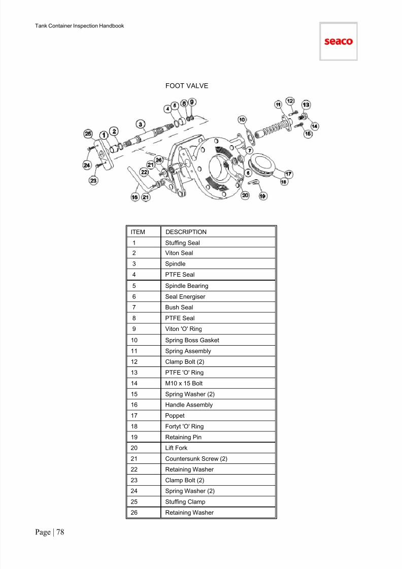
7/17/2019 Tank Container HandBook-2011
http://slidepdf.com/reader/full/tank-container-handbook-2011 79/90
Tank Container Inspection Handbook
Page | 78
FOOT VALVE
ITEM DESCRIPTION
1 Stuffing Seal
2 Viton Seal
3 Spindle
4 PTFE Seal
5 Spindle Bearing
6 Seal Energiser7 Bush Seal
8 PTFE Seal
9 Viton 'O' Ring
10 Spring Boss Gasket
11 Spring Assembly
12 Clamp Bolt (2)
13 PTFE 'O' Ring
14 M10 x 15 Bolt
15 Spring Washer (2)
16 Handle Assembly
17 Poppet
18 Fortyt 'O' Ring
19 Retaining Pin
20 Lift Fork
21 Countersunk Screw (2)
22 Retaining Washer
23 Clamp Bolt (2)
24 Spring Washer (2)
25 Stuffing Clamp
26 Retaining Washer
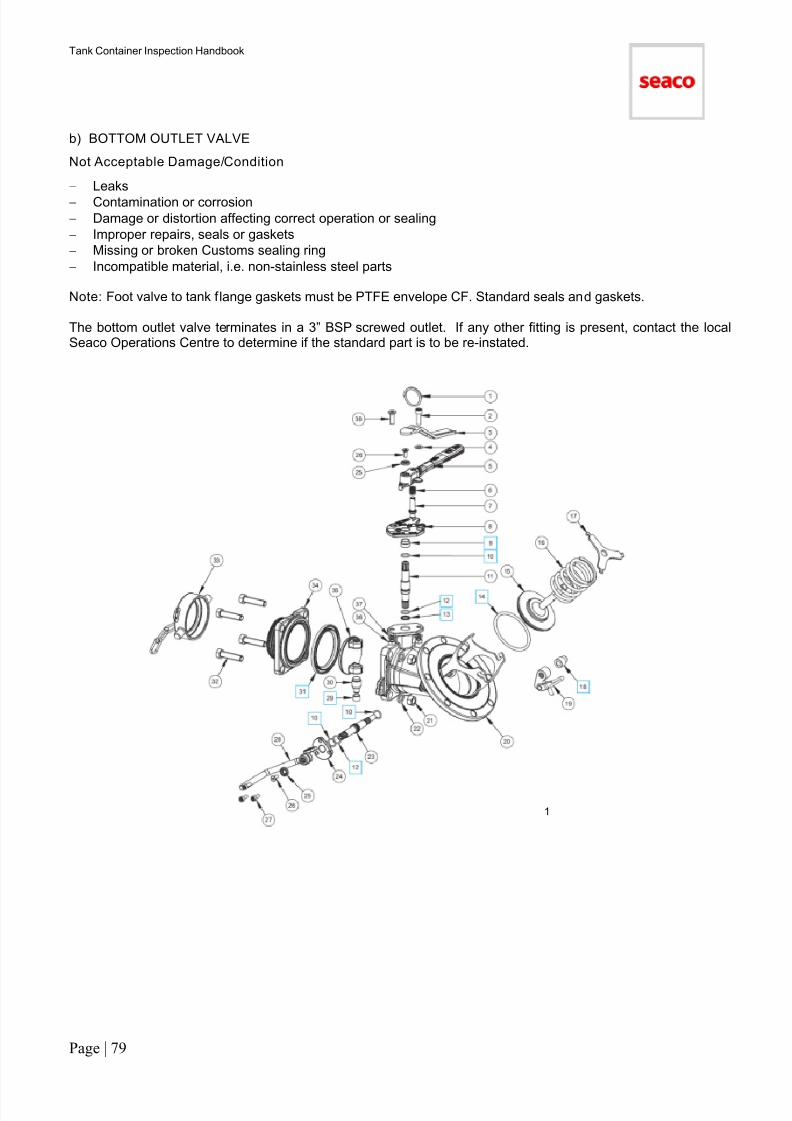
7/17/2019 Tank Container HandBook-2011
http://slidepdf.com/reader/full/tank-container-handbook-2011 80/90
Tank Container Inspection Handbook
Page | 79
b) BOTTOM OUTLET VALVE
Not Acceptable Damage/Condition
− Leaks
− Contamination or corrosion
− Damage or distortion affecting correct operation or sealing
− Improper repairs, seals or gaskets
− Missing or broken Customs sealing ring
− Incompatible material, i.e. non-stainless steel parts
Note: Foot valve to tank flange gaskets must be PTFE envelope CF. Standard seals and gaskets.
The bottom outlet valve terminates in a 3” BSP screwed outlet. If any other fitting is present, contact the localSeaco Operations Centre to determine if the standard part is to be re-instated.
1

7/17/2019 Tank Container HandBook-2011
http://slidepdf.com/reader/full/tank-container-handbook-2011 81/90
Tank Container Inspection Handbook
Page | 80
c) OUTLET BLANK (BLIND) FLANGE
Non Acceptable Damage/Condition
− Leaks
− Contamination or corrosion
− Missing customs sealing ring
− Damage or corrosion affecting operation
− Incompatible material, i.e. non-stainless steel parts
Note: Seaco standard is screw cap. If outlet blank (blind) flange fitted replace with screw cap.
d) SCREWED OUTLET CAP
Not Acceptable Damage/Condition
− Leaks− Contamination or corrosion
− Missing parts
− Non-stainless steel
− Damaged or improper screw threads
− Broken or missing wire or chain
− Damage or corrosion affecting operation
Note: Standard screw thread is BSP.
Acceptab le Damage/Cond it ion
− PTFE seals
Note: Replacement caps must be secured by a chain fitted to prevent cap hanging below ISO.
e) REMOTE TRIPNot Acceptable Damage/Condition
− Damage rendering remote trip inoperable
− Seized
− Broken thermal closure (when fitted)
− Insecure
Note: Remote trips are fitted as standard to bottom outlet >2.65 bar tank containers.
f) FUSIBLE LINK (THERMAL CLOSURE)
Not Acceptable Damage/Condition
- Damage rendering fusible link inoperable- InsecureNote: Fusible links are fitted as standard to post 2003 manufactured tank containers. Where fitted, the link mustremain in place.
7/17/2019 Tank Container HandBook-2011
http://slidepdf.com/reader/full/tank-container-handbook-2011 82/90
Tank Container Inspection Handbook
Page | 81
11. HEATING
a) STEAM TUBE AND CAP
Non Acceptable Damage/Condition
− Leaks
− Damaged screwed fittings
− Missing dust caps
− Missing or broken chain
− Distortions greater than 50% of steam tube depth
− Distortion to the tank shell (due to overpressure or ice expansion)
Acceptab le Damage/Cond it ion
− Tight dust caps which require to be removed by use of a normal wrench
Note: Steam tubes to be tested as part of the off hire leak check. In all cases of damage the steam tubes musthydro pressure tested.
Defective steam traps should be removed; replacement is not required.
Steam tube dust caps may be made from bronze, aluminium casting or stainless steel. Replacement caps mustbe of bronze, the most economical material.
b) TEMPERATURE GAUGE (THERMOMETER)
Non Acceptable Damage/Condition
− Not operating correctly
−
Broken facia or dial− Missing or insecure
− Improperly fitted
Acceptable Damage/Cond it ion
− Condensation which does not prevent legibility
− Non standard type
Note: Thermometers are fitted as standard to ALL insulated tank containers.
c) ELECTRIC HEATING
Not Acceptable Damage/Condition
− Non operational
− Missing parts
− Damage or deterioration that may allow moisture ingress to control boxes or elements
− Insecure components, cables or terminals.
− Corroded terminals or components
− Improper repairs
− Earth leakage less than 1 megohm
Note: All parts must be well maintained and fully operational.
An electric heating function test is required at off-hire (to prepare the repair estimate) and at on-hire (pre-tripinspection) for EVERY electrically heated tank container.
A supply cable of approximately 6m length and a CE17 plug are fitted as standard.

7/17/2019 Tank Container HandBook-2011
http://slidepdf.com/reader/full/tank-container-handbook-2011 83/90
Tank Container Inspection Handbook
Page | 82
12. MISCELLANEOUS
a) DECALS AND DATA PLATES
Not Acceptable Damage/Condition
− Insecure
− Missing or illegible plates
− Missing, illegible, obscured or partly missing decals
− Twisted or bent beyond limits of ISO
Acceptab le Damage/Cond it ion
− Scuffs and scratches
− Dents or distortion except as qualified above
Note: All statutory markings (decals and plates) required by applicable regulations must be present.
Inspect plates for security, missing rivets or electrolytic corrosion of rivets. Remedy as required.
The company logo (Seaco) is not a statutory marking and as such is not requi red.
If the logo is damaged or a repair is carried out over the logo then the logo should be either:
− repaired in part as necessary, can be part painted.
− replaced completely
− removed completely
Whichever is the cheapest option
TANK CONTAINER MARKINGS
Note: Some markings are only statutory if the tank container is operated in a specific country or region,e.g. ADR, RID or BAM.
2

7/17/2019 Tank Container HandBook-2011
http://slidepdf.com/reader/full/tank-container-handbook-2011 84/90
Tank Container Inspection Handbook
Page | 83
TANK CONTAINER MARKINGS (CONTINUED)
b) DOCUMENT HOLDER
Not Acceptable Damage/Condition
− Missing, defective or non-operational
− Insecure
− Blocked or no drain-hole
− Water filled
Acceptab le Damage/Condi tion
− Non standard type
c) SPILL BOX AND COMPARTMENTS
Not Acceptable Damage/Condition
− Non operational
− Damaged
− Twisted or bent beyond the ISO limits
− Splits or tears
− Cargo residue or waste material
− Blocked, damaged, missing drain tubes
− Insecure doors/lids where fasteners do not tightly secure the lid for transport
− Missing customs sealing ring and door fasteners− Pitting (see also section 9 regarding pitting to tank shell inside spill box)
Acceptab le Damage/Condi tion
− Dents, distortions or splits except as qualified above
Note: Where lids are fitted at original manufacture these lids must be replaced if missing or damaged beyondrepair. The majority of tank containers are not fitted with lids at original manufacture. Most tanks are fitted withhinges and fasteners in preparation to fit lid.
d) EARTH (Ground) LUG
Not Acceptable Damage/Condit ion
− Damaged, missing or painted

7/17/2019 Tank Container HandBook-2011
http://slidepdf.com/reader/full/tank-container-handbook-2011 85/90
Tank Container Inspection Handbook
Page | 84
13. TEST
a) Leak Test
Leak tests (pressurise with air at 1 bar) to tank and fittings are required under the following circumstances:
− As part of the depot survey to check the tank shell, valves, safety valves, steam and fittings
− As part of the completed repair inspection and quality process
− When tank containers are stored in depot for periods greater than six months from the time of the completedrepair inspection, a repeat leak test is required prior to delivery
This test does not replace the periodic leakage or hydrostatic test which is performed as part of the statutory 2.5or 5 year test procedures.
b) Leak Test Procedure
− The tank container should be pressurised with air as the pressurising medium. The test pressure should be
a minimum pressure of 1.0 bar and a maximum of 25% of the barrel’s Maximum Allowable WorkingPressure (MAWP)
− This test will be used to test the integrity of the tank barrel, valves, steam and fittings
− The pressurising medium should be introduced to the tank container and raised (slowly and with due care)to the required pressure. When the required pressure is reached it must be held for 10 minutes without lossin pressure
− The exterior flanges, valves and fittings must be checked for leakage by the application of soapy water.Leaks can be identified by the continual formation of bubbles in the solution when it is introduced around thearea being tested
− The internal seals to the bottom outlet valve should be tested using an apparatus similar to that shownbelow. Checking the foot valve and the outlet valve separately
− Due to the nature of the air test medium it might seep pass the sealing faces where a liquid will not leak.Because of this the surveyor might permit internal valve seals to seep an isolated bubble to one of thevalves in accordance with the manufacturer’s criteria
− Re-setting the foot valve (by opening and slamming) might be necessary to stop leaks
Not Acceptable Damage/Condition
− Leaks
Acceptab le Damage/Condi tion
− Manufacturers tolerance as noted on next page
Set-Up to Leak Test Bottom Outlet Valve

7/17/2019 Tank Container HandBook-2011
http://slidepdf.com/reader/full/tank-container-handbook-2011 86/90
Tank Container Inspection Handbook
Page | 85
Leakage Tolerance Criteria
c) Statutory Test
.
Determination of which statutory test to carry out must be based on the criterion below:
• A 2.5 year leak test should be carried out when a 2.5 year test is due (i.e. 2.5 years after the last 5 year test)providing the test is up to 3 months or less before or after test expiry
• Any tank container that requires a 2.5 year test but the test is more than 3 months after expiry date shouldbe given a 5 year test
• Any tank container that requires a 5 year test should be given a 5 year test• Any tank container arriving into depot with 9 months or less remaining test date should be detailed on the off
hire estimate for re-test
• Any tank container in depot under repair where the test date has 9 months or less remaining should betested at the time of repair
• Any tank container in depot where the unit is status ‘AVLB’ and the test becomes due within 6 monthsshould be tested (obtain authorisation via supplementary estimate procedure)
• Any tank container in depot to be delivered to a customer should have 6 months (or more) test validityremaining at the day of delivery (except when notified in writing to the contrary)
• 5 year re-testing is required after all welded repairs to the shell or conversion such as T11 to T14.
Note: Dangerous goods cargo may only be transported in a tank container that has a valid test certificate

7/17/2019 Tank Container HandBook-2011
http://slidepdf.com/reader/full/tank-container-handbook-2011 87/90
Tank Container Inspection Handbook
Page | 86
Section 9
CONVENTION FOR SAFE CONTAINERS (CSC)

7/17/2019 Tank Container HandBook-2011
http://slidepdf.com/reader/full/tank-container-handbook-2011 88/90
Tank Container Inspection Handbook
Page | 87
Section 9: Convention for Safe Containers
Contents of Section
Convention for Safe Containers (87)
Fitting the CSC Plate (87)
Marking the container to indicate that it is operated under ACEP (87)
Appendix 9.1: Data Plate (88)
Revisions (89)
CONVENTION FOR SAFE CONTAINERS(CSC)
1. INTRODUCTION
Every container must be checked on return to depot to ensure that it carries a valid data plate. This consolidateddata plate should incorporate a CSC plate. If the data plate does not include a CSC plate then this must be fittedseparately.
In addition every container must be checked to ensure that it is marked to indicate that it is operated underSeaco's Approved Continuous Examination Programme (ACEP). See paragraph 3 below for detailedinstructions.
2. FITTING A CSC PLATE
A new data plate must be fitted when:
−
The original data plate has been lost− The container has never been fitted with a data plate
Contact the local Seaco Operations Centre for the technical data, which must be stamped on the plate.
All letters and numbers stamped on the plate must be a minimum of 5mm in height. An example of a typicaldata plate and the data required is illustrated below.
The new CSC plate must be fixed in a readily visible place as close as possible to other existing approval platese.g. Customs Type Approval plate etc.
The majority of Seaco tank containers are fitted with a consolidated data plate, (as shown below).
Use 4mm diameter zinc p lated steel drive or self-sealing pu ll rivets to fix the plate to the tank frame.
3. MARKING THE CONTAINER TO INDICATE THAT IT IS OPERATED UNDER ACEP
Every tank container must be marked with the standard Seaco ACEP approval number or a decal bearing theapproval number ACEP-BDA-01 on or next to the CSC plate. This approval number is unique to Seaco and if adecal bearing any other approval number is found on the container it must be removed.
If the ACEP decal is missing, a decal bearing the above approval number must be fixed to the CSC plate in thesection entitled Next Examination Due. Alternatively, if there is insufficient space, fit the decal immediately nextto the CSC plate.
The standard ACEP decal is illustrated below:
Supplies of the Seaco ACEP decals can be obtained via Seaco Operation Centre.
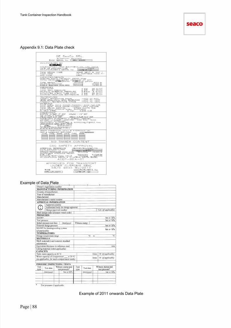
7/17/2019 Tank Container HandBook-2011
http://slidepdf.com/reader/full/tank-container-handbook-2011 89/90
Tank Container Inspection Handbook
Page | 88
Appendix 9.1: Data Plate check
Example of Data Plate
Example of 2011 onwards Data Plate

7/17/2019 Tank Container HandBook-2011
http://slidepdf.com/reader/full/tank-container-handbook-2011 90/90
Tank Container Inspection Handbook
Revisions:
01/09/2011 Customer Logo added to Detachable Parts Page 801/09/2011 ISO code change for Operator Markings Page 24
01/09/2011 Description of Damage Code IC amended Page 3901/09/2011 Description of Improper Repair amended Page 57


