NASA Technical Paper 2528 February 1986 186 6 An Approximate Buckling Analysis for Rectangular Orthotropic Plates With ^ Centrally Located Cutouts Michael P. Nemeth, Manuel Stein, and Eric R. Johnson 19951102 018 NASA DEPARTMENT Of ntrr N? :,. mAtriCS TECHNICAL EVALUATE ciNIt* DTI® QUALITY INSPECTED 9 DISTRIBUTION STATEMENT A Approved for public release; Distribution Unlimited
Transcript
NASA Technical Paper 2528
February 1986
186 6
An Approximate Buckling Analysis for Rectangular Orthotropic Plates With ^ Centrally Located Cutouts
Michael P. Nemeth, Manuel Stein, and Eric R. Johnson
19951102 018
NASA
DEPARTMENT Of ntrrN?:,. mAtriCS TECHNICAL EVALUATE ciNIt*
DTI® QUALITY INSPECTED 9
DISTRIBUTION STATEMENT A
Approved for public release; Distribution Unlimited
§str@ — 1 OF 2
***DTIC DOES NOT HAVE THIS ITEM*** — 1 - AD NUMBER: D440943 __ 5 _ CORPORATE AUTHOR: NATIONAL AERONAUTICS AND SPACE ADMINISTRATION
HAMPTON VA LANGLEY RESEARCH CENTER __ 6 _ UNCLASSIFIED TITLE: AN APPROXIMATE BUCKLING ANALYSIS FOR
RECTANGULAR ORTHOTROPIC PLATES WITH CENTRALLY LOCATED CUTOUTS. — 9 - DESCRIPTIVE NOTE: TECH REPT . , --10 - PERSONAL AUTHORS: NEMETH,M. P. ;STEIN,M. ;JOHNSON,E. R. ; --11 - REPORT DATE: FEB , 1986 --12 - PAGINATION: 19P --14 - REPORT NUMBER: L-16032 —18 - MONITOR ACRONYM: NASA —19 - MONITOR SERIES: TP-2528 —20 - REPORT CLASSIFICATION: UNCLASSIFIED --22 - LIMITATIONS (ALPHA): APPROVED FOR PUBLIC RELEASE; DISTRIBUTION
UNLIMITED. AVAILABILITY: NATIONAL TECHNICAL INFORMATION SERVICE, SPRINGFIELD, VA. 22161. NASA-TP-2528.
--33 - LIMITATION CODES: 1 24
2 OF 2 ***DTIC DOES NOT HAVE THIS ITEM***
— 1 - AD NUMBER: D439914
Alt-Z FOR HELP3 ANSI 3 HDX 3 3 LOG CLOSED 3 PRINT OFF 3 PARITY
NASA Technical Paper 2528
1986
NASA National Aeronautics and Space Administration
Scientific and Technical Information Branch
An Approximate Buckling Analysis for Rectangular Orthotropic Plates With Centrally Located Cutouts
Michael P. Nemeth and Manuel Stein Langley Research Center Hampton, Virginia
Eric R. Johnson Virginia Polytechnic Institute and State University Blacksburg, Virginia
t^«'^''^" A
public roiecse: y ■ ■ r <■• "> -f f• v
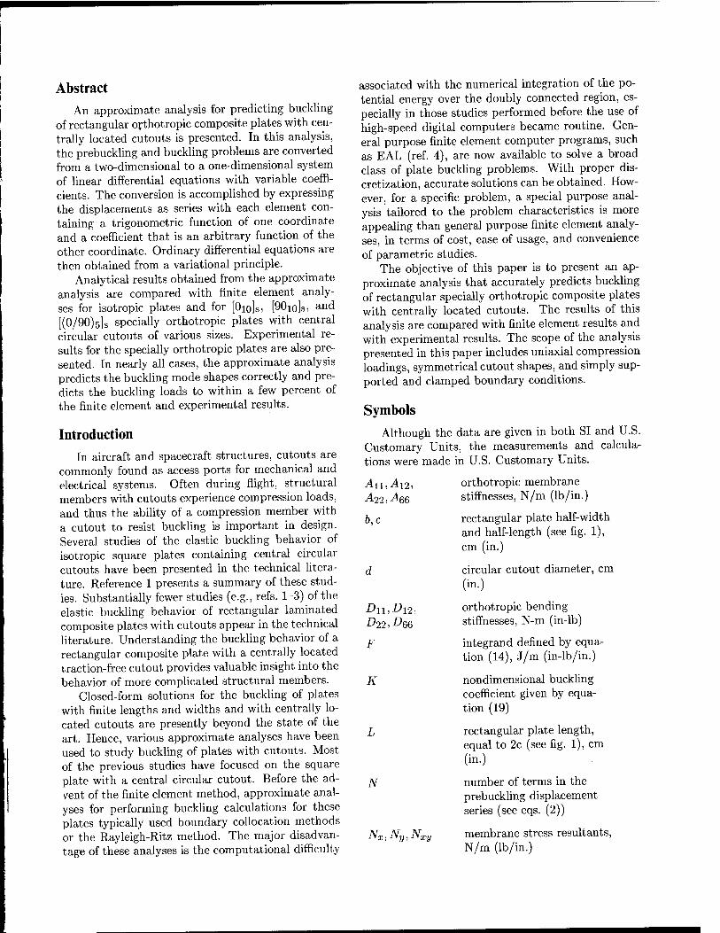
Abstract An approximate analysis for predicting buckling
of rectangular orthotropic composite plates with cen- trally located cutouts is presented. In this analysis, the prebuckling and buckling problems are converted from a two-dimensional to a one-dimensional system of linear differential equations with variable coeffi- cients. The conversion is accomplished by expressing the displacements as series with each element con- taining a trigonometric function of one coordinate and a coefficient that is an arbitrary function of the other coordinate. Ordinary differential equations are then obtained from a variational principle.
Analytical results obtained from the approximate analysis are compared with finite element analy- ses for isotropic plates and for [Oio]s, [90io]s, and [(0/90)ö]S specially orthotropic plates with central circular cutouts of various sizes. Experimental re- sults for the specially orthotropic plates are also pre- sented. In nearly all cases, the approximate analysis predicts the buckling mode shapes correctly and pre- dicts the buckling loads to within a few percent of the finite element and experimental results.
Introduction In aircraft and spacecraft structures, cutouts are
commonly found as access ports for mechanical and electrical systems. Often during flight, structural members with cutouts experience compression loads, and thus the ability of a compression member with a cutout to resist buckling is important in design. Several studies of the elastic buckling behavior of isotropic square plates containing central circular cutouts have been presented in the technical litera- ture. Reference 1 presents a summary of these stud- ies. Substantially fewer studies (e.g., refs. 1-3) of the elastic buckling behavior of rectangular laminated composite plates with cutouts appear in the technical literature. Understanding the buckling behavior of a rectangular composite plate with a centrally located traction-free cutout provides valuable insight into the behavior of more complicated structural members.
Closed-form solutions for the buckling of plates with finite lengths and widths and with centrally lo- cated cutouts are presently beyond the state of the art. Hence, various approximate analyses have been used to study buckling of plates with cutouts. Most of the previous studies have focused on the square plate with a central circular cutout. Before the ad- vent of the finite element method, approximate anal- yses for performing buckling calculations for these plates typically used boundary collocation methods or the Rayleigh-Ritz method. The major disadvan- tage of these analyses is the computational difficulty
associated with the numerical integration of the po- tential energy over the doubly connected region, es- pecially in those studies performed before the use of high-speed digital computers became routine. Gen- eral purpose finite element computer programs, such as EAL (ref. 4), are now available to solve a broad class of plate buckling problems. With proper dis- cretization, accurate solutions can be obtained. How- ever, for a specific problem, a special purpose anal- ysis tailored to the problem characteristics is more appealing than general purpose finite element analy- ses, in terms of cost, ease of usage, and convenience of parametric studies.
The objective of this paper is to present an ap- proximate analysis that accurately predicts buckling of rectangular specially orthotropic composite plates with centrally located cutouts. The results of this analysis are compared with finite element results and with experimental results. The scope of the analysis presented in this paper includes uniaxial compression loadings, symmetrical cutout shapes, and simply sup- ported and clamped boundary conditions.
Symbols Although the data are given in both SI and U.S.
Customary Units, the measurements and calcula- tions were made in U.S. Customary Units.
N°x Nx stress resultant in a plate without a cutout, N/m (lb/in.)
"er buckling load, N (lb)
5 number of terms in the
U, V
UB
UIS
Urn
Um
u0,«2fc-l> v2k-l
V0
W
W
WE
x,y,z
f.0 Po ^,0 cx' cj/' ixy
buckling displacement series (see eq. (13))
prebuckling displacements in the x- and y-directions, respectively, cm (in.)
bending energy, defined by equation (11), J (in-lb)
initial stress energy, defined by equation (12), J (in-lb)
membrane energy, defined by equation (1), J (in-lb)
energy integrand defined by equation (3), J/m (in-lb/in.)
generalized displacements for prebuckling problem, cm (in.)
displacement series parameter
out-of-plane buckling displacement, cm (in.)
rectangular plate width, equal to 26 (see fig. 1), cm (in.)
external work defined by equation (4), J (in-lb)
generalized displacements for buckling, cm (in.)
Cartesian coordinates, cm (in.)
differentiation of ( ) with respect to x
variational operator
midplane membrane strains of plate
nondimensional loading pa- rameter defined in equa- tions (2)
xM
A0,A2fc-
Analysis
applied normal stress resultant, N/m (lb/in.) (see fig. 1)
functions defined by equa- tion (5)
In this paper, the classical two-dimensional buck- ling analysis for plates is converted into a simpler approximate one-dimensional analysis following the Kantorovich method (ref. 5, pp. 304-337). The for- mulation of the present analysis consists of two parts: calculation of the in-plane stress distribution prior to buckling, referred to as the "prebuckling problem," and calculation of the buckling load, referred to as the "buckling problem." In the discussion that fol- lows, the requirements of the approximate analysis are described and the Kantorovich method is applied to obtain the one-dimensional prebuckling and buck- ling equations.
Plate Description
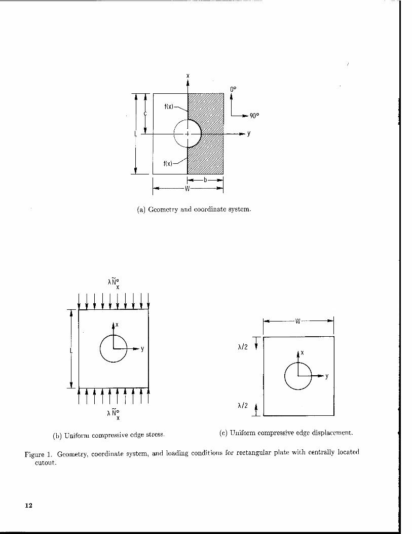
The formulation of the analysis as a one- dimensional problem implies certain symmetry prop- erties in the geometry, material properties, loading, and boundary conditions. The geometry, loading conditions, and coordinate system used in the anal- ysis are shown in figure 1. The plate has length L — 2c, width W = 2b, and uniform thickness and is referred to a right-handed Cartesian coordinate system with origin at the center of the plate. The cutouts must be centrally located and must possess shapes that are symmetrical with respect to the xz- and yz-planes. Similarly, the principal orthotropic material axes must coincide with the x- and y-axes of the plates. The loading is applied symmetrically at the x = ±c edges by either uniformly displacing the two opposite edges of the plate or by applying a uni- form normal stress to these edges (see fig. 1). Prior to buckling, the unloaded lateral edges of the plate at y — ±b are free to expand in-plane in the y-direction. At buckling, these edges are considered simply sup- ported. Only the shaded portion of the plate shown in figure 1 is used to derive the equations in this anal- ysis because of the symmetry discussed previously.
Prebuckling Analysis
Prior to buckling, the potential energy of the plate is the difference between the strain energy due to stretching Um (also referred to as the "membrane strain energy") and the work done by the external loads WE-
Exploiting the problem symmetry allows the strain energy prior to buckling to be expressed as
Um = a cJf(x) An(e°)2 + A22(e°vf
o \2 +2Anexe°y + Am(1°xyY\ dydx (1)
where f(x) is the curve shown in figure 1, which fol- lows the centerline of the plate and the cutout bound- ary; Aij are the orthotropic membrane stiffnesses; and e°, e°, and ^xy are the linear midplane strains of the two-dimensional theory of elasticity. Following the Kantorovich method, the prebuckling displace- ments are represented by kinematically admissible se- ries containing products of trigonometric functions of the y-coordinate and generalized displacements that are functions of the z-coordinate. The two major considerations used in this paper to select these se- ries are as follows: (1) the series should adequately approximate the in-plane displacements of the plates and (2) the series should not produce any nonzero resultant forces on the unloaded edges of the plates. These considerations led to selection of the following series to represent the prebuckling displacements of the plates:
N
u{x,y) = A < UQ(X) + )ju2k-i(x)cos
fc=i
N
(2k-1 2b
v{x,y) = X<v0y + ^2v2k-i(x)sm (2k- 1)^| fc=i
26 J
(2) where A is a nondimensional loading parameter that is increased monotonically from zero until buckling occurs. The term Awo in the series for u and the term Xvoy in the series for v represent the exact so- lution for a plate without a cutout. The remaining terms in the series represent corrections to the dis- placement field that account for the presence of a cutout. The constant VQ is selected to satisfy the condition that no resultant normal forces act on the unloaded edges of the plate (ref. 1). Substituting the displacement series into the strain-displacement relations of the two-dimensional theory of elasticity, then substituting the resulting expressions into equa- tion (1), and integrating over y yields the membrane strain energy in the following form:
Ur, X' i: Umdx (3)
where Um is a function of the generalized displace- ments UQ,U2k-\i and ^fc-l (^ = l>2,...,iV) and
their first derivatives with respect to x, that is, U'Q, u2k-v and v2k-l (fc = l,2,...,JV).
The external work done by the applied loads is given by
WE = -XN°f [u(c,y)-u(-c,y)}dy (4) J — b
where XN° is the applied uniform stress loading shown in figure 1. Substituting the displacement se- ries for u(x, y) given in equations (2) into equation (4) and integrating over y yields the external work in the following form:
Win = -2\2N° UQ(X)K.Q(X)
N
+ X^2fc_i(a;)A2fc-i(z) fe=l
x=+c
(5)
The functions Ao(x) and A2fc_i(x) are determined directly from integration of the displacement series.
Applying the principle of minimum potential en- ergy results in the following ordinary differential equations and boundary conditions for the prebuck- ling problem
Differential equations (—c<x<c)
dÜm d (dUm
8UQ dx \ du'n
dÜm d I dU„
du2k-i dx \du'2k_l
dUr, d ( dUn
dv2k-i dx \dv'2k_1
= 0
= 0
= 0
(6)
for k= 1,2,3,...,N.
Boundary conditions
TZ+ *&)*«
du,m +hk-iKJ Su2k-i
dUn
- x=+c
x=—c
x=+c
x=—c
x=+c
= 0
= 0
dv' ÖV- 2fc-l
2/5-1.
= 0
(7)
for k= 1,2,3,...,TV.
For the uniform edge-displacement loading, the displacement is prescribed to be a unit displacement times the loading parameter (see fig. 1), and the shear stress resultant is required to vanish at x = ±c, the edges of the plate. Thus, for this loading case,
v^frc) - (2k ■
u0{±c) = =F
«2fc-l(±c) = 0
l)^2fc-i(±c) = 0
1
(8)
for k = 1,2,3,..., AT. For the uniform edge-stress loading condition, the normal stress resultant is pre- scribed to be equal to the loading parameter times an arbitrary applied load N°, and the shear stress resultant is required to vanish at x = ±c (see fig. 1). Thus, for this loading case,
Anu'0(±c) + A12v0 = -N° '
4n«2k-i(±e) + A12(2k - l)^v2fc-i(±c) = 0
«2fc-i(±c) - (2fc - l)^u2fc-i(±c)
(9) for jfc= 1,2,3, ...,iV.
Buckling Analysis
Using the Trefftz criterion, the buckling problem can be posed as
S(UB + Uis) = 0 (10)
where Uß and Ujg are the contributions of the bending energy and the membrane energy (referred to as the "initial stress energy"), respectively, to the second variation of the total potential energy (ref. 1). Exploiting the problem symmetry allows these energies to be expressed as
UB I / [Dll{w,xx)2 + D22{w,yy f J-cJ fix)
+ 2D12{w,xxw,yy) +4Dee(w,Xy )2] dy dx (11)
and
Uis= f / [Nx{v>,x? + Ny{w,yf J-c Jf(x)
+ 2NxywtXwjy] dy dx (12)
where f(x) is the same curve shown in figure 1 and described in the prebuckling analysis section, Dij are the orthotropic bending stiffnesses, ./Vz, Ny, and
Nxy are the prebuckling membrane stress resultants, and subscript commas followed by letters denote par- tial differentiation with respect to the coordinate corresponding to each letter. Both Uß and Ujg are derived using the Von Karman nonlinear strain- displacement relations and the principle of mini- mum potential energy. Following the Kantorovich method, the out-of-plane displacement w(x, y) is ap- proximated by a kinematically admissible trigono- metric series given by
w {x, y) = ^2 w2fc-i(z) cos [(2fc - 1) — k=\
(13)
This series also satisfies the natural boundary condi- tions when the unloaded edges are simply supported.
Substituting the above series expressions for the out-of-plane displacement and the expressions for the prebuckling stress resultants (obtained from solution of eqs. (6)) into equations (11) and (12), and inte- grating over y yields a functional of the form
UB + Uis -s: F dx (14)
where F is a function of the generalized displace- ments W2k-i {k = 1,2,3,..., S) and their first and second derivatives with respect to x, w'2k_1 and
w, 2k- .x (fc = l,2,3,...,5). Applying equation (10) to this functional leads
to the following stability equations and boundary conditions:
Differential equations (c < x < c)
dF dF + dF
dw2k-\ dx \dw'2k_lJ dx2 {dw^^
for k = 1,2,3,...,S.
Boundary conditions
(15)
for k = 1,2,3,...,S. The boundary conditions for the buckling prob-
lem considered in this paper are simply supported
or clamped edges at x = ±c. For simply supported edges, the boundary conditions are
W2fc-l(±c) = 0
w2k-l(±c) = ° (17)
for k = 1,2,3,..., 5. For clamped edges, the bound- ary conditions are
(18) «>2fc-i(±c) = tn
«4-i(±c) = °J
for fc = 1,2,3,...,S.
Calculation of the Buckling Load
The approximate analyses described in the previ- ous sections for the prebuckling and buckling prob- lems result in two systems of linear ordinary differ- ential equations. The analysis for the prebuckling problem produces 2N + 1 simultaneous second-order differential equations and 4N + 2 boundary condi- tions. Some of the boundary conditions are nonho- mogeneous. The analysis for the buckling problem produces 5 simultaneous fourth-order homogeneous differential equations and 45 homogeneous bound- ary conditions. Together these differential equations and corresponding boundary conditions for the buck- ling problem constitute an eigenvalue problem for the nondimensional loading parameter A in equations (2). The smallest nontrivial value of A corresponds to buckling.
In both the prebuckling and the buckling prob- lems, the ordinary differential equations have vari- able coefficients that prevent closed-form solutions from being obtained. To obtain solutions, the equa- tions are solved numerically by the finite difference method. Details of the finite difference formulation for the prebuckling analysis corresponding to N = 3 and for the buckling analysis corresponding to 5 = 3 are presented in reference 6.
Experiment The specimens tested in this investigation were
fabricated from commercially available 450 K (350° F) cure graphite-epoxy preimpregnated tapes. The tapes were made of unidirectional Hercules AS4 graphite fibers preimpregnated with Hercules 3502 thermosetting epoxy resin. The tapes were laid up to form 20-ply-thick laminates having [Oio]s, [(0/90)s]s, and [90io]s stacking sequences. The laminates were cured in an autoclave using the manufacturer's rec- ommended procedures. After curing, the laminates were ultrasonically C-scanned to establish specimen
quality and then machined into test specimens. All specimens were 25.4 cm (10 in.) long and 25.4 cm (10 in.) wide, and the loaded edges were machined flat and parallel to permit uniform compressive load- ing. Centrally located circular cutouts were ma- chined into the panels with diamond-impregnated core drills. The hole diameters ranged from 0 to 15.88 cm (6.25 in.). One side of each specimen was painted white to reflect light so that a moire fringe technique could be used to monitor out-of-' plane deformations.
The specimens were loaded in axial compression with a 1.33-MN (300-kip) capacity hydraulic testing machine. The loaded ends of the specimens were clamped by fixtures during testing, and the sides were simply supported by restraints that prevented the specimen from buckling as a wide column. All specimens were loaded slowly to approximately twice the buckling load. A typical specimen mounted in the test fixture is shown in figure 2.
A total of 20 specimens were tested; they were designated Al through A7 for the [Oio]s specimens, Bl through B6 for the [90io]s specimens, and Cl through C7 for the [(0/90)s]s specimens. The an- alytical results presented in the results and discus- sion section of this paper are based on length and width dimensions of 24.13 cm (9.50 in.). These di- mensions represent the portion of the plate between edge supports of the test fixture (see fig. 2) that de- forms out of plane when buckling occurs. The analyt- ical results are also based on the average value of sev- eral thickness measurements made on each specimen. These average thickness values were determined to be 2.718 mm (0.107 in.) for the [Oio]s laminates, 2.692 mm (0.106 in.) for the [90io]s laminates, and 2.794 mm (0.110 in.) for the [(0/90)5]s laminates.
Electrical resistance strain gages were used to monitor strains, and direct-current differential trans- formers were used to monitor axial displacements and displacements normal to the specimen surface. Elec- trical signals from the instrumentation and the cor- responding applied loads were recorded on magnetic tape at regular time intervals during the tests.
Results and Discussion
Results obtained with the analysis presented in this paper were compared with finite element results and with experimental results to determine the ac- curacy of the approximate analysis. The converged finite element results were obtained from the com- puter program EAL (ref. 4). The results for the approximate analyses for N = 1 and 2 and 5 = 1 and 2 were obtained from computer programs simi- lar to the computer program described in reference 6.
The computer program described in reference 6 cor- responds to the approximate analysis for N = S = 3 in equations (2) and (13).
The plates used to assess the accuracy of the ap- proximate analysis were square because square plates exhibit larger differences in the displacement and stress fields for the loading conditions and boundary conditions considered in this paper than do rectan- gular plates. Previous studies (refs. 1-3) have shown that the buckling load of a simply supported square isotropic plate decreases monotonically with increas- ing cutout size when a uniform compressive stress is applied to two opposite edges of the plate. When the loading is applied as a uniform compressive displace- ment of two opposite edges, the buckling load of these plates decreases slightly and then increases with in- creasing cutout size, until the cutout size becomes larger than approximately 70 percent of the plate width. Rectangular plates with aspect ratios greater than 1 typically exhibit buckling behavior bounded by the buckling behavior for the two loading condi- tions of the square plates. Hence, square plates are expected to serve as a more rigorous test of the abil- ity of the approximate analysis to predict buckling accurately.
The analytical and experimental results presented in the following sections of this paper are for square plates with centrally located circular cutouts having ratios of diameter to plate width d/W ranging from 0 to 0.66. The influence of orthotropy on the ac- curacy of the analysis is investigated by studying [Oio]s, [90io]s, and [(0/90)s]s specially orthotropic laminates. These laminates represent the two ex- treme cases and one intermediate case of laminate orthotropy.
All results presented in this section are for lami- nates made of graphite-epoxy plies having longitudi- nal modulus Ex of 127.8 GPa (18.5 x 10⁶ psi), trans- verse modulus E2 of 11.0 GPa (1.6 x 10⁶ psi), in- plane shear modulus G12 of 5.7 GPa (0.832 x 10⁶
psi), and major Poisson's ratio v\i of 0.35. A nom- inal ply thickness of 0.127 mm (0.005 in.) is used in the analytical comparisons with the finite element analyses.
Analytical Results
Accuracy of the prebuckling analysis. The stress distribution in a plate prior to buckling must be de- termined in order to determine the plate's buckling load. For plates without cutouts, finding an analyti- cal expression for the prebuckling stress distribution is often trivial. However, for plates with finite dimen- sions and with a cutout, finding closed-form solutions for the prebuckling stress distribution is presently
beyond the state of the art. For the analysis pre- sented herein, the prebuckling stresses are approxi- mated by the truncated displacement series given by equations (2). A highly accurate prebuckling stress analysis may not be needed to predict accurately the buckling load if the overall load distribution in the plate is adequately represented. To assess the appli- cability of the prebuckling analysis presented in this paper for predicting buckling of plates with cutouts, the Nx and Ny stress resultant distributions at the net section of the plates (located at x = 0 in fig. 1) are examined. Results are presented in figures 3 to 8 for both isotropic and specially orthotropic plates. The stress resultant distributions in figures 3 to 8 are normalized by the constant value of Nx in the corresponding plate without a cutout, denoted N°.
In figure 3, the Nx distributions at the plate net section obtained for N = 1,2, and 3 in equa- tions (2) are compared with finite element results for an isotropic plate loaded by uniform edge dis- placement. The isotropic plate considered in figure 3 has an intermediate ratio of cutout diameter to plate width, d/W = 0.3. The results shown in figure 3 indicate that the best approximation to the finite el- ement results is obtained for N = 3 (values of N greater than 3 were not considered). Similar results were obtained for two other cutout sizes, d/W = 0.1 and 0.6.
The finite element results for d/W = 0.1 indicated a stress distribution similar to the stress distribution for a compression-loaded infinite plate with a hole. Most of the plate is uniformly stressed and local stress concentration and gradient are present near the hole. The approximate analysis for N = 3 models the uniformly stressed region of the plate very well, but lacks the higher harmonics in the displacement series to give the correct value of the stress concentration near the cutout. An accurate representation of this localized stress concentration may not be required in the prebuckling analysis. The approximate analysis must accurately predict the overall load distribution in the plate, and for N = 3, it accomplishes this objective.
The stress distribution for the plate with d/W — 0.6 is different from the stress distributions for the plates with d/W = 0.1 or 0.3. For this large cutout size, the stress distribution is nonuniform across the entire plate net section without a local stress concen- tration near the cutout. The results obtained with the approximate analysis suggest that higher har- monics in the displacement series are not required to predict reasonably well the stress distribution in the plate with d/W = 0.6. The approximate analy- sis predicts the overall load distribution in the plates with the larger cutout sizes reasonably well.
The approximate analysis for plates with interme- diate cutout sizes is less accurate than the approx- imate analysis for plates with small or large cutout sizes. Plates with intermediate cutout sizes, such as d/W = 0.3, have a large region with a severe stress gradient and a small region with a uniform stress dis- tribution. However, even with the reduced pointwise accuracy of the analysis, the overall load distribution in the plate is adequately represented.
The directional nature of the approximate anal- ysis suggests that orthotropy influences the accu- racy of the prebuckling stress predictions. Stress distributions obtained from the finite element anal- ysis and the approximate analysis for N = 3, for the displacement-loaded plates, are presented in fig- ures 4 to 7 for the [Oio]s and [90io]s laminates with d/W — 0.3. The results shown in figures 4 to 7 indi- cate that orthotropy does influence the present analy- sis. For the Nx distribution at the net section of the plate, the approximate analysis predicts the stress distributions reasonably well, with the results for the [90io]s laminate (fig. 4) agreeing with the finite ele- ment analysis results better than the results for the [Oio]s laminate (fig. 5). For the Ny distribution at the net section of the plate, the results of the approxi- mate analysis for the [Oio]s laminate (fig. 6) agree with the finite element results substantially better than those for the [90io]s laminate (fig. 7). The ap- proximate analysis results for Ny in the [90io]s lam- inates exhibit the largest differences from the finite element results.
Contour plots of the Nx distribution obtained from the finite element analysis and from the approx- imate analysis for N = 3 are shown in figure 8 for a [90io]s laminate with d/W = 0.4 (Nx is normalized by N°). These contour plots suggest that the approx- imate analysis predicts the overall axial load distri- bution in the plate reasonably well. Similar results were obtained for Nx, Ny> and Nxy distributions for [Oio]s and [90io]s laminates with d/W = 0.1, 0.4, and 0.6. These results also suggest that the approx- imate analysis adequately predicts the overall load distribution in a plate except for Ny in the [90io]s laminates with d/W > 0.3. The approximate anal- ysis generally predicts the load distributions in the [90io]s laminates, but not to the same accuracy as for the other laminates.
The results shown in figures 3 to 8 suggest that the approximate prebuckling analysis for N = 3 is not suitable for highly accurate stress analysis of plates with cutouts. However, the approximate anal- ysis appears to predict the overall load distribution in the plates reasonably well and may be sufficient for predicting buckling loads.
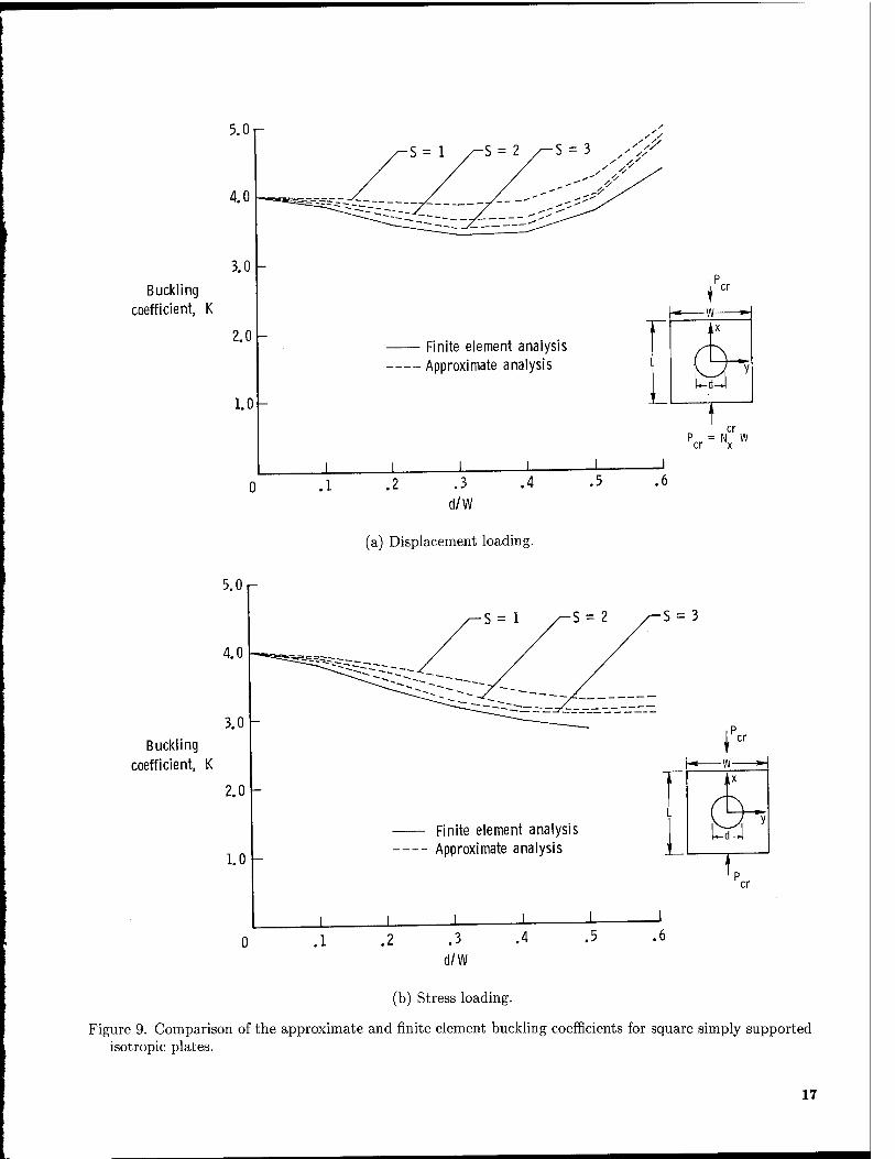
Accuracy of the buckling analysis. The accuracy of the buckling displacement approximations given by equation (13) is evaluated using N — 3 in the pre- buckling analysis. Buckling results for displacement- loaded and stress-loaded isotropic square plates with central circular cutouts are shown in figure 9. The plates are simply supported on all edges, and the buckling load is expressed in terms of a nondimen- sional buckling coefficient given by
N"W2
K = x
n2y/DnD22 (19)
For the stress-loaded plates, N" is the critical value of the applied loading. For the displacement- loaded plates, Nx
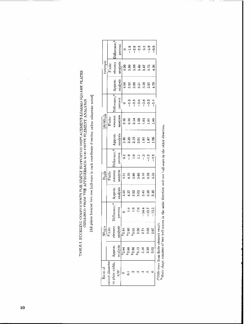
r is obtained by dividing the total axial load at buckling PCT by the width of the plate. The results presented in figure 9 show a compari- son of the buckling coefficients obtained using equa- tion (13) with 5 = 1,2 and 3 with the corresponding results obtained from finite element analyses. The re- sults in figure 9 show that for both loading cases, the buckling loads converge monotonically from above toward the finite element solutions as the value of 5 increases. The best agreement between the approx- imate and finite element analyses is for 5 = 3, with the difference in the buckling coefficients being less than 6 percent for d/W = 0, 0.1, 0.2, 0.3, 0.4, and 0.5 and about 10 percent for d/W — 0.6. Moreover, the results for the isotropic plates given in table I indicate that both the approximate (for N = 5 = 3) and finite element analyses predict the same buck- ling mode shapes. The buckling mode shapes consist of a single half-wave along the direction of the ap- plied loading and a single half-wave in the direction perpendicular to the loading.
The influence of orthotropy on the accuracy of the approximate analysis is indicated by the results presented in figure 10 and table I. Approximate results obtained using N = S = 3 and finite element results are presented in the figure and in the table for simply supported [Oio]s, [90io]s, and [(0/90)5]s
displacement-loaded laminates with d/W = 0 to 0.6. The best agreement between the approximate and finite element results was obtained for the [Oio]s and the [(0/90)5]s laminates. The buckling loads from the two analyses for these laminates differed by less than 6 percent for all cutout sizes considered. For the [90io]s laminates, the difference in the buckling loads increased as d/W increased: the loads for d/W = 0, 0.1, and 0.2 differed by less than 2 percent; for d/W = 0.3, by slightly less than 8 percent; and for d/W = 0.4, 0.5, and 0.6, by 13 to 15 percent. These differences in the buckling loads for [90io]s laminates with d/W = 0.4, 0.5, and 0.6 suggest that this group
of laminates is the most sensitive to the directional nature of the approximate analysis. This sensitivity is manifested in the Ny prebuckling stress prediction.
For all cases presented in table I, with the ex- ception of the [90io]s laminate with d/W > 0.2, the approximate analysis predicts the buckling loads to within 10 percent of the finite element results and predicts the same buckling mode shapes. For the [90io]s laminate with d/W > 0.3, the approximate and finite element analyses predict buckling loads that differ by less than 15 percent. However, the approximate analysis for d/W = 0.3 predicts a differ- ent mode shape from that predicted by the finite ele- ment analysis. This incorrect prediction of the mode shape is attributed to the lower accuracy of the Ny
prebuckling stress resultant approximation for the [90io]s laminates, due to the directional nature of the approximate analysis previously discussed.
Experimental Results
The buckling loads obtained for N — S = 3 in the approximate analysis are compared with experi- mental buckling loads for simply supported isotropic plates in reference 1. The cutout sizes range from d/W — 0 to 0.6 and results are presented for both uniform edge-stress and uniform edge-displacement loadings. For all cases considered in reference 1, good agreement between the present analysis and the ex- periments is indicated.
In this study, experimental buckling loads were obtained and compared with the corresponding an- alytical buckling loads for the [Oio]s, [(0/90)s]s, and [90io]s laminates previously described to further as- sess the accuracy of the approximate analysis. The results of this comparison are presented in figure 11 and tables II to IV. The experimental buckling load for each specimen was obtained by determining the value of the applied load at which the slope of the load vs. end-shortening curve changed. A shadow moire technique for monitoring the out-of-plane dis- placement was also used to verify the experimental buckling load calculations and to identify the buck- ling mode shapes. The buckling mode shapes of the plates indicated in tables II to IV consist of either one or two half-waves along the direction of the applied loading. For all the plates, the buckling mode shapes consist of a single half-wave in the direction perpen- dicular to the loading direction. The experimental and analytical buckling loads shown in figure 11 and listed in tables II to IV agree well except for the [Oio]s laminate with d/W = 0.6 and 0.66 and the [(0/90)5]s laminate with d/W = 0.66. The analytical results for the [(0/90)5]s laminates with d/W < 0.6 and [Oio]s laminates with d/W < 0.4 are within 5 percent of the experimental results. The analytical
and experimental results for the [Oio]s laminates with d/W = 0.42 differ by approximately 12 percent, but with d/W > 0.6, they differ by more than 25 percent. The agreement between the analytical and experi- mental results for the [90io]s laminates is typically not as good as for the other laminates with similar cutout sizes, especially for the smaller cutout sizes, but the differences between the experimental and an- alytical buckling loads never exceed 13 percent. The analytical buckling load for the [90io]s laminate with d/W = 0.66 was within 3 percent of the experimen- tal buckling load. The [90io]s laminate designated as specimen B2 in table III buckled into a mode shape that was not predicted by the approximate analysis. The difference between the analytical and experimen- tal buckling loads is approximately 9 percent for this specimen. This result reinforces the previous sugges- tion that the analysis does not approximate the Ny
prebuckling stress resultant for the [90io]s laminates as well as it does for the other laminates.
The [Oio]s and [90io]s laminates represent ex- treme degrees of orthotropy, and the most disagree- ment between the analytical and experimental buck- ling loads occurs for these laminates, with the [90io]s laminates typically showing the worst disagreement overall. This larger disagreement for the [90io]s lam- inates is attributed to the lower accuracy of the Ny
prebuckling stress resultant predicted by the approx- imate analysis for the [90io]s laminates compared with that for the [Oio]s and [(0/90)s]s laminates. The buckling loads for the [(0/90)5]s laminates (laminates without an extreme degree of orthotropy) are pre- dicted accurately by the approximate analysis for cutout sizes with d/W < 0.6. In addition, both the experimental and the analytical results for the [(0/90)5]s laminates indicate that the buckling load increases as the cutout size increases, as do the re- sults reported by Ritchie and Rhodes (ref. 7) for isotropic plates. This analytical and experimental trend suggests that the buckling resistance of a plate might be improved by optimizing its cutout size as well as its stacking sequence.
Concluding Remarks
An analysis for predicting buckling of rectangu- lar orthotropic composite plates with centrally lo- cated cutouts has been presented. In this analysis, the prebuckling and buckling problems are converted into systems of linear ordinary differential equations with variable coefficients. The conversion is accom- plished by expressing the displacements as series with each element containing a trigonometric function of one coordinate and a coefficient that is an arbitrary
8
function of the other coordinate. Ordinary differen- tial equations are then obtained from a variational principle.
Buckling loads obtained from the approximate analysis are compared with buckling loads obtained from finite element analyses for isotropic plates and for [Oio]s! [90io]s, and [(0/90)s]s specially orthotropic plates. The plates contain central circular cutouts having diameters d ranging in sizes from 0 to nearly 70 percent of the plate width (0 < d/W < 0.66). Ex- perimental results are also presented for the specially orthotropic laminates.
The comparison of the approximate and finite el- ement results suggests that a highly accurate point- wise prebuckling stress analysis is not essential for accurately predicting the buckling load, as long as the prebuckling stress analysis gives the general load distribution in the plate. The comparison also in- dicates that in most cases the approximate analy- sis predicts the buckling loads to within 10 percent of the buckling loads obtained from a finite element analysis. Orthotropy plays an important role in the accuracy of the approximate analysis (with regard to the directional dependence associated with the choice of the displacement series) and is most important in the analysis of the [90io]s laminates. For the [90io]s
laminates with d/W > 0.3, the approximate analy- sis predicts the overall prebuckling load distribution with less accuracy than for the other laminates and results in differences from 13 percent to 15 percent in the buckling loads obtained by the approximate and finite element analyses. For the [Oio]s and [(0/90)5]s
specially orthotropic plates and isotropic plates, the differences between the buckling loads obtained from the approximate analysis and the buckling loads ob- tained from the finite element analysis are at most 10 percent for cutout sizes with d/W < 0.6.
Experimental results presented indicate that the approximate analysis predicts buckling loads to within 13-percent accuracy in most cases. Specifi- cally, the approximate analysis predicts buckling of the [(0/90)5]s laminates to within 5 percent of the ex- perimentally obtained buckling load for cutout sizes
up to d/W = 0.6. Similar accuracy in the buckling load predictions was obtained for the [Oio]s laminates with cutout sizes up to d/W < 0.4. The approxi- mate analysis results for the [Oio]s laminates with d/W = 0.6 and 0.66 and for the [(0/90)5]s laminates with d/W = 0.66 differed from the experimental re- sults by more than 25 percent. The buckling load ob- tained from the approximate analysis for the [90io]s
laminate with d/W = 0.66 was within 3 percent of the experimental buckling load. Both the analytical and the experimental results presented in this paper indicated that increasing the cutout size in a given plate does not always reduce the buckling load.
NASA Langley Research Center Hampton, VA 23665-5225 October 30, 1985
References 1. Nemeth, Michael Paul: Buckling Behavior of Or-
thotropic Composite Plates With Centrally Located Cutouts. Ph.D. Diss., Virginia Polytech. Inst. & State Univ., May 1983.
2. Martin, James: Buckling and Postbuckling of Laminated Composite Square Plates With Reinforced Central Cir- cular Holes. Ph.D. Diss., Case Western Reserve Univ., 1972.
3. Preobrazhenskii, I. N.: Research Pertaining to Stability of Thin Plates With Holes. Soviet Appl. Mech., vol. 16, no. 7, Jan. 1981, pp. 557-574.
4. Whetstone, W. D.: EISI-EAL Engineering Analysis Language Reference Manual—EISI-EAL System Level 2091. Engineering Information Systems, Inc., July 1983.
5. Kantorovich, L. V.; and Krylov, V. I. (Curtis D. Benster, transl.): Approximate Methods of Higher Analysis. Inter- science Pub., Inc., c.1964.
6. Nemeth, Michael P.: A Buckling Analysis for Rectan- gular Orthotropic Plates With Centrally Located Cutouts. NASA TM-86263, 1984.
7. Ritchie, D.; and Rhodes, J.: Buckling and Post-Buckling Behavior of Plates With Holes. Aeronaut. Q., vol. 26, pt. 4, Nov. 1975, pp. 281-296.
CO
fa S3 a, fa <; a M CO
Q fa
a*
co fH
>i H
o fa co H 2 H 5 fa fa
£« °£ g« a o
u P m
CO g
c3
_o3
"ft
0 a; 40
S Ö 00 00 CO CM re re a) cj o ^H CM CM CO
,<1J CD 1 1 1 SB ft Q
(X 0) I t 1 s 0) to
r> CO re CO h~ iO CD
o CO
g fa
o 00
CO
«3
CO CO CO t~ CO CO ■*
X -2
■< cä
o CO re ^H an t- re o re CD IO IO re t- ■0" CO CO CO CO co ^p
a 0J +j % ° CO CO CD 00 CO ■* CD o o j—t CM CM CO CO IO
,0) CD SB a Q
-*-3 CO iO <u
11 1 s <D CO
-*J co CO ■* CO ■* 1-H CD
o fa CM
CO
CM CM
re T—1
U0 00 00
>< .s O co en r» re t—1 TH t- CD
& ^ ■* CO ^H O re oo re IM IM CM CM w ^H ^H
<! CO
G
CD +j w Ö CM en O ^H CO CM 00 CD CJ ^H ^ ^H TJH
fCD CD to a Q
o -fj
1 § T—1 CO CO CO ■* CM CM
n lO co re CD •* CO co
p. fa Tf ■* CO CO CO co co a; cö
* -K o 5
«d cö
o r~ CM CM IO CD 00 IO CO re CD Tfl CO ■* ^p ■* CO CO CO CO CO
Ö
1 « en f-1
S P.
■* o CD ^ t- LO
o ^H
1 7 CO CO
1 1
Q
+3 CO
o o '3
■5t< o T-H o rH CO t-
p £■ 00 CM
re CM
o CO
re CM
1-
CM
CD CD
CM CM gi fa CD ce
-o .o -o
* 2 8 'S ■* CO 00 CM O re co fc, >v co on re T—( re o & "3 er ö
CM CM CM CO CO CM CO ■o -o -CJ -o
■< CO
u
CD
*3 S
J3
n .3 ^ CM CO ■5f IO CO V0 -Ö CD S?
O
o P. O
cc3
T3
§
Si
Ö cß cc "55 S o O CD
cÖ CD
CD m
CD ,2
IS O
10
TABLE II. EXPERIMENTAL AND ANALYTICAL BUCKLING LOADS FOR CLAMPED [Oio]s LAMINATES
[All plates buckled into one half-wave in each coordinate direction]
"Difference from experiment. 6Mode shape consists of two half-waves in the axial direction and one in the other direction.
11
(a) Geometry and coordinate system.
AN0
x
'' If If If If If If If If "
TfTTTTT
A/2
AN° x
(b) Uniform compressive edge stress.
A/2
(c) Uniform compressive edge displacement.
Figure 1. Geometry, coordinate system, and loading conditions for rectangular plate with centrally located cutout.
12
Figure 2. Specimen mounted in test fixture.
Finite element analysis Approximate analysis
N = 1 X/2f
L-85-6801
l~d-l
Figure 3. Comparison of the approximate and finite element Nx prebuckling stress distributions at x — 0 for a displacement-loaded isotropic plate. d/W — 0.3.
13
Finite element analysis
Approximate analysis
No
Q ■—y
Figure 4. Comparison of the approximate and finite element Nx prebuckling stress distributions at x = 0 for a displacement-loaded [90io]s laminate. d/W — 0.3.
3.0
2.0
l\l° x
1.0
Finite element analysis
Approximate analysis
X/2^ Q
Cutout boundary
.2 .3
y/W
.5
Figure 5. Comparison of the approximate and finite element iVx prebuckling stress distributions at x = 0 for a displacement-loaded [Oio]s laminate. d/W = 0.3.
14
N° x
.lOr
.05
.05
Finite element analysis
Approximate analysis
N = 3
Cutout boundary
.1 .2 .3 y/W
.5
X/2^_ &
Figure 6. Comparison of the approximate and finite element Ny prebuckling stress distributions at x = 0 for a displacement-loaded [Oio]s laminate. d/W = 0.3.
1.0
.5
-.5
-1.0 .1
Finite element analysis
Approximate analysis
' ~~~A /^N = 3 ( 1
~\-^ \ \llS~ \^\ c ̂
h d
-Cutout boundary
_L .2 .3
y/W .4 .5
Figure 7. Comparison of the approximate and finite element Ny prebuckling stress distributions at x = 0 for a displacement-loaded [90io]s laminate. d/W = 0.3.
15
Q.71—v 0.54 0.37 ^0.20
1.05
(a) Finite element analysis.
0.5-x 0.25—v r0.38 r0.63 ^0.75
(b) Approximate analysis.
Figure 8. Comparison of the approximate and finite element Nx/N° prebuckling stress resultant contours for the displacement-loaded [90io]s laminate. d/W = 0.4.
16
Buckling coefficient, K
2.0
1.0
Finite element analysis Approximate analysis
i .3
d/W
.5
\r" — w—*■
,1
L
cr P = N W cr x
.6
(a) Displacement loading.
5.0 r
Buckling coefficient, K
3.0 -
2.0
1.0
S = 3
Finite element analysis Approximate analysis
.2 .3
d/W
.4
f» ,|X
cr
(b) Stress loading.
Figure 9. Comparison of the approximate and finite element buckling coefficients for square simply supported isotropic plates.
17
Buckling coefficient,
K
cr
,|X
<a i
cr
Figure 10. Comparison of the approximate and finite element buckling coefficients for the displacement-loaded [Oio]s) [(0/90)5]s, and [90io]s simply supported laminates. N = S = 3.
Buckling load, 20
Pcr,kN
Experiment Analysis
°10
(0/90L
90. 10
,v |X
®t £,
Figure 11. Experimental and approximate buckling loads for clamped specially orthotropic laminates.
18
. — fc 1. Report No.
NASA TP-2528 2. Government Accession No. 3. Recipient's Catalog No.
4. Title and Subtitle
An Approximate Buckling Analysis for Rectangular Orthotropic Plates With Centrally Located Cutouts
5. Report Date
February 1986
6. Performing Organization Code
505-33-33-06 7. Author(s)
Michael P. Nemeth, Manuel Stein, and Eric R. Johnson 8. Performing Organization Report No.
L-16032 9. Performing Organization Name and Address
NASA Langley Research Center Hampton, VA 23665-5225
10. Work Unit No.
11. Contract or Grant No.
13. Type of Report and Period Covered
Technical Paper 12. Sponsoring Agency Name and Address
National Aeronautics and Space Administration Washington, DC 20546-0001 14. Sponsoring Agency Code
15. Supplementary Notes
Michael P. Nemeth and Manuel Stein: NASA Langley Research Center, Hampton, Virginia. Eric R. Johnson: Virginia Polytechnic Institute and State University, Blacksburg, Virginia.
16. Abstract An approximate analysis for predicting buckling of rectangular orthotropic composite plates with centrally located cutouts is presented. In this analysis, the prebuckling and buckling problems are converted from a two-dimensional to a one-dimensional system of linear differential equations with variable coefficients. The conversion is accomplished by expressing the displacements as series with each element containing a trigonometric function of one coordinate and a coefficient that is an arbitrary function of the other coordinate. Ordinary differential equations are then obtained from a variational principle. Analytical results obtained from the approximate analysis are compared with finite element analyses for isotropic plates and for [Oio]s, [90io]s, and [(0/90)5]s specially orthotropic plates with central circular cutouts of various sizes. Experimental results for the specially orthotropic plates are also presented. In nearly all cases, the approximate analysis predicts the buckling mode shapes correctly and predicts the buckling loads to within a few percent of the finite element and experimental results.
17. Key Words (Suggested by Authors(s))
Plates with cutouts Buckling analysis Kantorovich method
18. Distribution Statement
Unclassified—Unlimited
Subject Category 39
19. Security Classif. (of this report)
Unclassified 20. Security Classif. (of this page)
Unclassified 21. No. of Pages
19 22. Price
A02
For sale by the National Technical Information Service, Springfield, Virginia 22161 NASA-Langley, 1986