18
TCD-2, TCD-4 TIME CODE DISPLAY TIME – DATE CLOCK COUNTER – TIMER Symmetricom, Inc. Tel: 707-528-1230 Santa Rosa, CA 95403 Oct-08 Printed in USA

TCD-2, TCD-4
TIME CODE DISPLAY
TIME – DATE CLOCK COUNTER – TIMER
Symmetricom, Inc. Tel: 707-528-1230 Santa Rosa, CA 95403 Oct-08 Printed in USA

TCD Clocks User Manual Rev 1.0.1 - Oct-08 Symmetricom®, Inc. 2
TABLE OF CONTENTS
Introduction ...............................................................................................................................................................................4 IRIG-B .....................................................................................................................................................................................5 SMPTE ....................................................................................................................................................................................5 Operation ...................................................................................................................................................................................5
Operating Environment ...........................................................................................................................................................5 Configuration .............................................................................................................................................................................5 Configuration - default ................................................................................................................................................................5 Configuration - Basic ..................................................................................................................................................................5 Operation As A Time/Date Display ..............................................................................................................................................7 Programming - Time/Date Display Manually .........................................................................................................................7 Daylight Savings Time ............................................................................................................................................................7 Operation As A Timer/Counter ...............................................................................................................................................8 Programming - Timer Function Manually ...............................................................................................................................8 Configuraion – Advanced, Via Serial Port ...........................................................................................................................10 Troubleshooting Tips.............................................................................................................................................................11
Specifications.............................................................................................................................................................................12 Time Code Input ....................................................................................................................................................................12 Configuration – RS232 Serial Port ........................................................................................................................................14 Physical..................................................................................................................................................................................14 Power Requirements ..............................................................................................................................................................15 Operating/Storage Temperature & Humidity ........................................................................................................................15 Compliance ............................................................................................................................................................................16 Limited Warranty...................................................................................................................................................................17 Limitation of Liability ...........................................................................................................................................................17 Proprietary Notice..................................................................................................................................................................17
Certificate of Volatility

TCD Clocks User Manual Rev 1.0.1 - Oct-08 Symmetricom®, Inc. 3
DISCLAIMER The information contained in this document is subject to change without notice. Symmetricom, Inc. (hereinafter SYMMETRICOM) makes no warranty of any kind with regard to this material, including, but not limited to, the implied warranties of merchantability and fitness for a particular purpose. SYMMETRICOM shall not be liable for errors contained here in or for incidental or consequential damages in connection with the furnishing, performance, or use of this material. See important limited warranty at the end of this document.
TCD Clocks User Manual Rev 1.0.1 - Oct-08 Symmetricom®, Inc. 4
Introduction
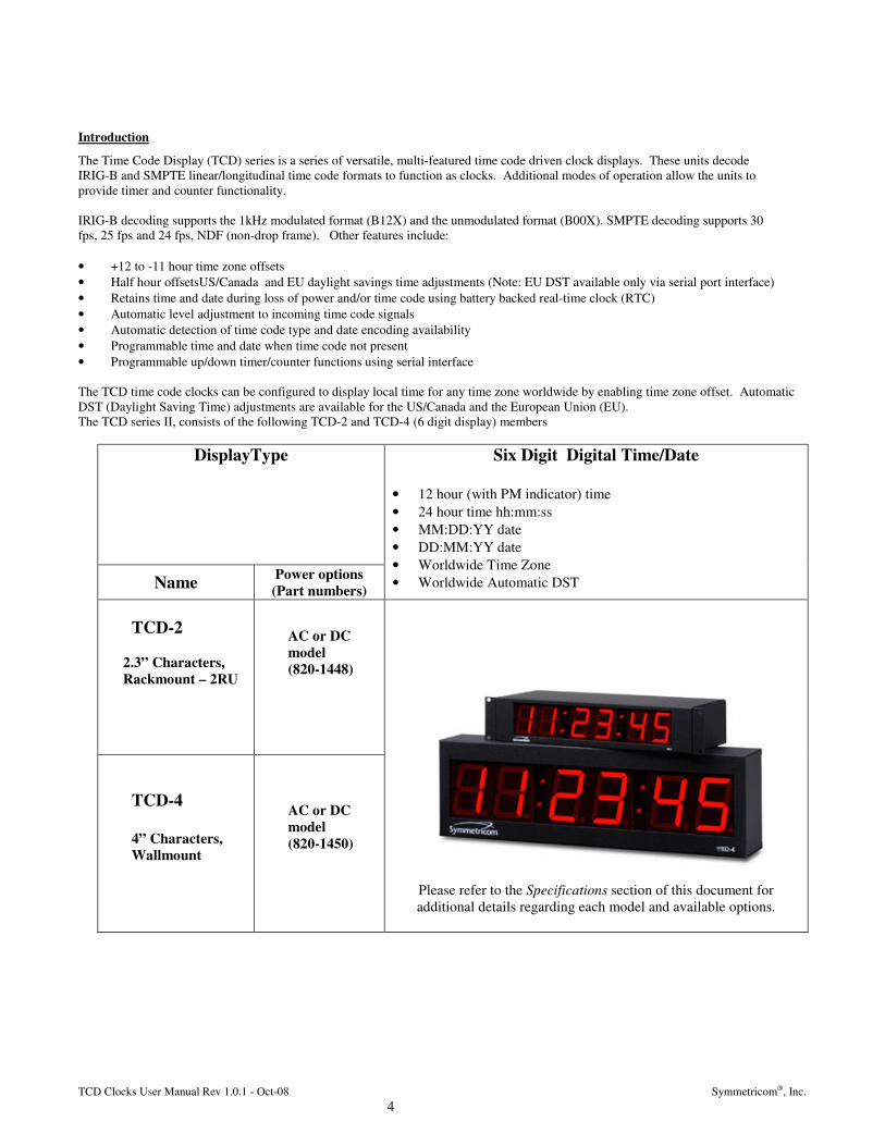
The Time Code Display (TCD) series is a series of versatile, multi-featured time code driven clock displays. These units decode IRIG-B and SMPTE linear/longitudinal time code formats to function as clocks. Additional modes of operation allow the units to provide timer and counter functionality. IRIG-B decoding supports the 1kHz modulated format (B12X) and the unmodulated format (B00X). SMPTE decoding supports 30 fps, 25 fps and 24 fps, NDF (non-drop frame). Other features include: • +12 to -11 hour time zone offsets • Half hour offsetsUS/Canada and EU daylight savings time adjustments (Note: EU DST available only via serial port interface) • Retains time and date during loss of power and/or time code using battery backed real-time clock (RTC) • Automatic level adjustment to incoming time code signals • Automatic detection of time code type and date encoding availability • Programmable time and date when time code not present • Programmable up/down timer/counter functions using serial interface The TCD time code clocks can be configured to display local time for any time zone worldwide by enabling time zone offset. Automatic DST (Daylight Saving Time) adjustments are available for the US/Canada and the European Union (EU). The TCD series II, consists of the following TCD-2 and TCD-4 (6 digit display) members
DisplayType
Name Power options (Part numbers)
Six Digit Digital Time/Date
• 12 hour (with PM indicator) time • 24 hour time hh:mm:ss • MM:DD:YY date • DD:MM:YY date • Worldwide Time Zone • Worldwide Automatic DST
TCD-2
2.3” Characters, Rackmount – 2RU
AC or DC model (820-1448)
TCD-4 4” Characters, Wallmount
AC or DC model (820-1450)
Please refer to the Specifications section of this document for additional details regarding each model and available options.

TCD Clocks User Manual Rev 1.0.1 - Oct-08 Symmetricom®, Inc. 5
IRIG-B
Defined by the Range Commanders Council, U.S. Army White Sands Missile Range. The format is used by military, government, power industry, and many other commercial and industrial applications. The TCD decodes IRIG-B in both a 1kHz modulated (IRIG-B12X) and unmodulated (a.k.a pulse-width coded/DC level shifted - DCLS) (IRIG-B00X) format. All formats of IRIG-B time code decoded by the TCD use the time of year information BCD (binary coded decimal). All formats of IRIG-B time code decoded by the TCD also use the extended year information in the control functions (CF) as defined by the IEEE 1344 specification and/or IRIG Standard 200-04. SBS (Straight Binary Seconds) information is not decoded. Manchester format/encoding is not supported. SMPTE
Defined by the Society of Motion Picture and Television Engineers. SMPTE time code is available in frame rates of 30, 25, and 24 frames per second. The TCD time code clock display supports the three SMPTE 12M listed here in longitudinal /linear forward running modes only.* All formats of SMPTE time code decoded by the TCD use the full date information in the user bits as defined in the specifications section of this document. Additional user bit encoding is not utilized. * The TCD does not support decoding of SMPTE drop-frame, reverse running,, VITC, NTSC, or color frame time codes.
Operation
Operating Environment
The TCD series is not water or moisture proof, it is designed for indoor use in a controlled environment. Treat it as you would any other delicate electronic device and do not expose it to water, excessive heat or physical abuse. See the specifications sections for details of the environmental operation limits.
Configuration
Basic operation of the TCD series is configured via the S1 and S2 switch banks accessible on the back panel of the clock. Advanced operational features are available via an RS-232 serial interface. Basic configurations made with the DIP switch banks S1 and S2 will be retained during power cycles. Advanced configuration functions and features will not be retained during power cycles, therefore it is highly recommended to utilize a UPS when powering from AC, or secondary DC input to retain advanced configuration settings.
Configuration - default
A TCD ships from the factory with all S1 and S2 switches in the OFF position. This configuration results in the time displayed as: no time zone offset, no daylight saving time adjustment, and 24 hour display format.
Configuration - Basic
The S1 switches configure the fundamental mode of operation: Function S1-1 S1-2 Time display OFF OFF Date display OFF ON Timer/counter ON OFF Note: The fundamental mode of operation may be switched dynamically during clock operation.

TCD Clocks User Manual Rev 1.0.1 - Oct-08 Symmetricom®, Inc. 6
The S2 switches configure modifiers to the fundamental mode of operation: Note: The mode of operation may be switched dynamically during clock operation. S2 switches 1-4 configure the time zone (hour) offset: Hour offset S2-1 S2-2 S2-3 S2-4 0 hour offset OFF OFF OFF OFF 1 hour offset ON OFF OFF OFF 2 hour offset OFF ON OFF OFF 3 hour offset ON ON OFF OFF 4 hour offset OFF OFF ON OFF 5 hour offset ON OFF ON OFF 6 hour offset OFF ON ON OFF 7 hour offset ON ON ON OFF 8 hour offset OFF OFF OFF ON 9 hour offset ON OFF OFF ON 10 hour offset OFF ON OFF ON 11 hour offset ON ON OFF ON 12 hour offset OFF OFF ON ON S2 switch 6 ON- applies an additional ½ hour to the offset specified by switch positions 1-4.
Function S2-6 No ½ hour offset OFF Enable ½ hour offset ON S2 switch 5 configures positive/negative time zone (as set with S2 switch positions 1-4 & 6). Function S2-5 Time offset is positive OFF Time offset is negative ON S2 switch 7 configures daylight savings time adjustment option. (See Daylight Savings Time) Function S2-7 DST adjustment disabled OFF DST adjustment enabled ON S2 switches 8 and 9 configure brightness intensity of the clock display. Level S2-8 S2-9 Brightest OFF OFF Intermediate (brighter) ON OFF Intermediate (dimmer) OFF ON Dimmest ON ON
S2 switch 10 configures time display format. Format S2-10 24-hour OFF 12-hour ON S2 switch 11 configures date display format. Format S2-11 US (MM/DD/YY) OFF European (DD/MM/YY) ON S2-12 is reserved. Note: All S2 switch functions may be changed dynamically during clock operation.
1

TCD Clocks User Manual Rev 1.0.1 - Oct-08 Symmetricom®, Inc. 7
Operation As A Time/Date Display
Insert the power cord or power supply into an appropriate AC source. After application of power the TCD will go through an internal checkout. Time from the real-time clock backup will then be displayed until a time code signal is acquired. If time code has never been applied to the clock dashed lines will be displayed until time code is acquired or the operator programs a time. Connect a source of IRIG-B or SMPTE time code to the input connector (see specifications section for supported formats). The time should appear on the display within 120 seconds of application of time code. If the time code signal is lost or disconnected the TCD will continue to display time based on its internal reference until the time code signal is returned. If the clock is unable to achieve a time code lock see the section entitled Troubleshooting Tips. The colons of the clock display will flash when the time or date displayed is not locked to time code. When time code is present and decoding properly the colons will remain steady-on. When operating in time/date display mode the operator may program time and date information into the clock at any time. [Note: when time and/or date information is available from the time code source it will always override any operator-programmed information.] In some situations time code may be providing time but not date information. Under these circumstances the operator may still program time/date. Any programmed time will be ignored but programmed date will be retained. This feature facilitates use of the clock’s daylight savings time function even when date information is not provided by time code. If the TCD is configured for a 12-hour time display mode an AM/PM indicator will appear in the bottom right corner of the display during the PM hours. In the event that a time code source is not present, the unit is designed to operate as a standard (stand-alone) clock. However, the time and date must be entered manually. Programming the time and date manually is accomplished via the MODE, UP, and DOWN buttons located on the back panel of the clock
Programming - Time/Date Display Manually
When the clock is in time/date display mode the first press of the MODE button will enter configuration mode. The first stage of configuration is for the date. The portion of the date currently available to be adjusted will be flashing. The order of the month and day values displayed in configuration mode will depend upon the date presentation format switch (S2-11). The UP and DOWN buttons will increment and decrement the flashing value. When the operator is done programming the currently selected value, or does not wish to change it, pressing the MODE button again will move on to the next value. When pressing the MODE button on the third value (year) configuration will switch to stage 2. The second stage of configuration is for the time. The portion of the time currently available to be adjusted will be flashing. Time is programmed in the same manner as date. When pressing the MODE button on the third value (seconds) the programmed date/time values will “take” and the clock will resume ticking forward. Remember that time and/or date information in time code, when available, will always override operator-programmed information.
Daylight Savings Time
When enabled, the TCD will apply an extra hour of offset to the incoming time code during US/Canadian-defined daylight savings time. The TCD series II firmware version 2.0.8 or later uses the US/Canada DST standard where Daylight savings time begins on the second Sunday of March at 2:00AM and ends on the first Sunday of November at 2:00AM. IMPORTANT NOTE:: To enable daylight saving (summer time) rules for the European Union, the serial port interface must be used. Configuration information that is setup using the serial interface is not retained during a power cycle, power loss, or brown out. The TCD will revert to its default configuration as defined by the DIP switches for the unit. US/Canada daylight saving time will be used by default if DST is enabled. Therefore, always use a UPS (uninterruptible power supply) to avoid having to re-configure the clock display.

TCD Clocks User Manual Rev 1.0.1 - Oct-08 Symmetricom®, Inc. 8
IMPORTANT NOTE: The incoming time code must have a date encoded in a format recognized by the TCD, or the correct date must be programmed into the TCD, for daylight savings time adjustments to be performed. For best reliability Symmetricom, Inc. recommends a time code source that encodes full date information. In order to use the Automatic Daylight Saving Time feature, the date or year information must be encoded in the time code.(see specifications section for details). SMPTE time code formats, the date must be encoded in the user bits . IRIG-B year decoding is supported for the CF (Control Function) Bits per the IEEE 1344 standard or the IRIG Standard 200-04. The TCD will automatically detect a recognized date encoding format in time code. Note: If your time code source is already making adjustments for daylight savings time do not enable this feature in the TCD.
Operation As A Timer/Counter
In basic configuration mode, the TCD display can function as a clock (time or date) or a count up timer . Using the advanced configuration mode which utilizes the serial port, the TCD display can function as either a clock (time or date), a timer (up/down) or a counter (up/down).
Programming - Timer Function Manually
Place the TCD series II clock to timer/counter display mode by setting the DIP switch S1-1 to ON. If you have not already done so, apply power to the unit. After each application of power the TCD will go through an internal checkout. A time value of 00:00:00 will be displayed. If the clock has never before been used as a timer, a default end time of 00:00:15 will be preloaded and used. When the clock is in timer mode the first press of the MODE button will enter the time entry configuration mode. Any time between 00:00:00 and 23:59:59 may be programmed. Date is not supported in timer/counter mode , therefore count up/down sequences may not span more than a 24-hour period When programming a count-up timer you are programming the end time for the count sequence. The UP and DOWN buttons will increment and decrement the flashing value for each currently selected time field (hours, minutes, or seconds). [Note: Pressing and holding the UP or DOWN buttons in configuration mode will incrementally increase the speed of the directional adjustment. ] When the operator is done programming the currently selected value, or does not wish to change it, pressing the MODE button again will move on to the next value. When pressing the MODE button on the third value (seconds) the programmed time will be stored then displayed, and the timer will then wait for the load event and then a start event to initiate the timer sequence. A start event (or load event) pulse (or trigger) is defined as providing a logic low to pin 1 of the DB-9 connector located on the back panel of the clock. This can be achieved by either a momentary switch or relay closure to connect pin 1 to pin 5 (ground) of the DB-9 connector or via a TTL logic low signal. The duration of the start closure should be at least 50 ms and not more than 100ms. Upon start, the clock will revert to 00:00:00 then begin counting up to the programmed end time. When the end time is reached the display will flash three times , then revert to the end time count waiting for the next load and start event triggers.

TCD Clocks User Manual Rev 1.0.1 - Oct-08 Symmetricom®, Inc. 9
The timer (count up) mode is programmed by the operator.
Select Display MODE Timer Set DIP switch S1-1 to ON
Enter Program Mode to Set the Time/Timer Sequence
Enter/program the desired time/timer value while viewing the front LED display of the clock.
Press the Mode button once to enter the program mode.
The front LED display of the clock will flash the HH (hours) digits.
• Set Hours
Enter the desired HH (hours) using the UP/DOWN buttons. Press the Mode Button once to accept the value and advance to the MM (minutes) digits.
• Set Minutes
Enter the desired MM (minutes) using the UP/DOWN buttons. Press the Mode Button once to accept the value and advance to the SS (seconds) digits.
• Set Seconds
Enter the desired SS (seconds) using the UP/DOWN buttons. Press the Mode button once to accept the value.
Program Complete
The time is now programmed. The clock display will no longer flash the digits.
Load Timer
Apply a /Trigger pulse to Pin 1 of the DB9 connector to load the timer. See specifications for details. The display will show all zeroes.
Trigger Timer
Apply a /Trigger pulse to Pin 1 of the DB9 connector to load the timer. See specifications for details. The timer will begin the sequence and the display will count up once per second to the desired end count time. When the end time is reached, the display will flash three times
Reload and Retrigger Timer The timer may be reloaded and retriggered
by following the previous two steps.

TCD Clocks User Manual Rev 1.0.1 - Oct-08 Symmetricom®, Inc. 10
Configuraion – Advanced, Via Serial Port
The TCD may be configured or setup using one of two methods: manually with the switches and the momentary push buttons located on the rear of the unit (basic configuration) , or via software using the configuration port located on DB9 connector of the rear of the unit to access the advanced features. This section discusses utilizing the serial port interface. Programming the TCD via software is accomplished by using the communications port(s) located on the DB9 connector on the rear of the unit. Display mode, brightness,, timezone offsets, EU or US/Canada DST, firmware version and other configuration features are also controllable or programmable via the built in RS-232 port. A rudimentary sample serial interface application with GUI (Graphical User Interface) has been provided, as-is, to assist the user who does not wish to develop an application for controlling the TCD display. [Note for Programmers and developers: please see the accompanying serial port protocol specification, sample application, and sample application source code located on the CD that came with your TCD display. The sample application source was developed and compiled in C++, using Microsoft Visual Studio 2005] Connect the null modem serial cable supplied with your TCD display. The start event may occur based upon either of the following conditions:
1. a start event pulse (basic and advanced modes) 2. a command issued via the RS232 serial port (advanced mode only). 3. a preset time, programmed via the RS232 serial port (advanced mode only)
The counter/timer function may be triggered by an external pulse or a momentary switch closure (basic and advanced) , or via software command (advanced only). In timer mode, the trigger pulse input allows the timer to be started, paused, and continued using subsequent pulse inputs. In counter mode, each pulse is registered as a count. The start event pulse or trigger (/TRIG) is defined as providing a logic low to the appropriate pin of the DB-9 connector located on the back panel of the clock. This can be achieved by either a momentary switch or relay closure to connect the pin 1 to pin 5 (ground of the DB-9 connector), or a active low TTL signal pulse. The duration of the start closure should be at least 50 ms and not more than 1000ms. The communications/programming port is for setup/configuration only. The communications cable should be limited to 3m (meters) or less for the RS-232. Pinouts for the DB9 connector are in the specifications section of this manual. Note: All communications with the clock are at 19200 baud, 8 data bits, 1 stop bit, no parity. A null modem cable has been provided with the TCD. For connecting the TCD to a host computer the user must either: use the provided null modem cable (serial communication only), build a custom cable, or purchase a cable from Symmetricom, Inc.
DO NOT USE A SERIAL CABLE WHICH WILL CONNECT PINS 1, 4, 6, 7, 8 or 9 TO THE HOST (COMPUTER) RS-232 VOLTAGE LEVELS. DOING SO MAY DAMAGE THE TCD AND VOID YOUR WARRANTY.
TCD Clocks User Manual Rev 1.0.1 - Oct-08 Symmetricom®, Inc. 11
Troubleshooting Tips
Problem: Clock is unable to “lock” to time code after 2 minutes. Possible reasons/solutions: 1. Clock is not currently connected to a time code source. Verify that all cables are properly connected. 2. There is a problem with the cabling between the clock and the time code source. Verify that all cables and connectors
are working, in good condition, and that proper pinout connections have been observed. 3. There is a ground loop or other type of interference between the clock and the time code source. Verify that a common
ground exists between the clock and the time code source. If the cabling distance between the time code source and clock is large you may want to consider inserting an audio distribution amplifier between the devices.
4. The signal level of the incoming time code is out of the range of the time code decoder’s circuitry. See the clock specification section for acceptable signal level ranges.
5. The signal level of the incoming time code is fluctuating or has changed. The signal level must be stable for the TCD to detect and decode the time code. Restart the TCD device to re-initiate the auto-detection of time code.
6. The time code being fed to the TCD is not a recognized format. Verify that your time code source is providing one of the time code formats that the TCD can decode.
Problem: Clock is not displaying the correct local time or date. Possible reasons/solutions: 1. The time code source is not referenced to your local time zone. Possibly it is referenced to UTC (GMT) or other another
time zone. Determine the time zone reference of your time code source then set the clock’s time zone offset accordingly to arrive at a correct displayed local time/date.
2. Your time code source and your TCD are both set with time zone and/or DST offsets. Determine the time zone reference of your time code source then set the clock’s time zone offset accordingly to arrive at a correct displayed local time/date.
3. Your time code source is not providing the time/date that you expect. Contact the individual responsible for the time code source for more information.
4. Your unit has lost power and any configuration settings for EU daylight saving (summer time) and time zone. Re-enable via the serial port interface and place the unit on a UPS.
Problem: Clock did not properly negotiate the daylight time to standard time (or vice-versa) transition. Possible reasons/solutions: 1. Your time code source is not providing date information and a valid date was never programmed into the TCD. Valid
date information is required to provide the daylight savings time adjustment feature. 2. Your time code source already provides the daylight savings time adjustment. The daylight savings time adjustment
feature in the TCD should be disabled. 3. Your time code source or the TCD clock does not have the correct DST firmware installed. 4. The daylight saving DIP switch is not enabled. Enable the DIP switch for DST. 5. Your unit has lost power and any configuration settings for EU daylight saving (summer time) and time zone. Re-enable
via the serial port interface and place the unit on a UPS. If these troubleshooting tips do not solve your problem, please contact technical support.

TCD Clocks User Manual Rev 1.0.1 - Oct-08 Symmetricom®, Inc. 12
SPECIFICATIONS
Time Code Input Type:..................................... LTC (Longitudinal/Linear Time Code), forward running, automatic detection, auto-gain adjust Level Range………………….1 to 16 Vpp Impedance...............................Typically >10 K ohm Connector...............................BNC female, isolated IRIG Format: ........................IRIG-B(12X) 1kHz, amplitude modulated (3:1 mark to space ratio), BCD, CF *, no SBS IRIG-B(00X) pulse-width coded, DC level shifted , BCD, CF*, no SBS (reported as zero filled)
X - 3rd Digit
Coded Expression
Designation
Explanation:
For Automatic DST adjustment to function properly the TCD requires the date information (including the year)
0 BCDTOY, CF, SBS
Year is automatically detected if CF to IEEE 1344 year encoding. Automatic DST is available. Else, year will be zero filled and default to Jan 01, 2000 (01:01:00 US format), or date will not be valid. Date/year must be entered manually.
1 BCDTOY, CF
Year is automatically detected if CF to IEEE 1344 year encoding. Automatic DST is available. Else, year will be zero filled and default to Jan 01, 2000 (01:01:00 US format), or date will not be valid. Date/year must be entered manually.
2 BCDTOY Date/year must be entered manually in order to use Automatic DST. Date retained in RTC.
3 BCDTOY, SBS Date/year must be entered manually in order to use Automatic DST. Date retained in RTC.
4 BCDTOY, BCDYEAR, CF, SBS Year is automatically detected, Automatic DST available.
5 BCDTOY, BCDYEAR, CF Year is automatically detected, Automatic DST available.
6 BCDTOY, BCDYEAR Year is automatically detected, Automatic DST available.
7 BCDTOY, BCDYEAR, SBS Year is automatically detected, Automatic DST available.
* CF bits year encoding as specified below in table. Year Encoding (IRIG-B):..... Included in control functions (CF) per IEEE 1344 specification and IRIG Standard 200-04 NOTE: Remaining IEEE1344 CF 10-27 bits are masked, and disregarded.
IRIG-B Position ID
Control
Function Bit
Designation
Explanation
P49 -- P5 Position identifier #5 P50 1 Units of Year, BCD 01 Last 2 digits of year in BCD P51 2 Units of Year, BCD 02 IBID P52 3 Units of Year, BCD 04 IBID P53 4 Units of Year, BCD 08 IBID P54 5 Not used Unassigned P55 6 Tens of Year, BCD 10 Last 2 digits of year in BCD P56 7 Tens of Year, BCD 20 IBID P57 8 Tens of Year, BCD 40 IBID P58 9 Tens of Year, BCD 80 IBID P59 -- P6 Position identifier #6

TCD Clocks User Manual Rev 1.0.1 - Oct-08 Symmetricom®, Inc. 13
SMPTE Formats: .................. SMPTE 12M, 24, 25 or 30 fps NDF (Non Drop-Frame) Longitudinal, forward running. Date Encoding (SMPTE):.......Included in user bits per following specification
Date encoding of SMPTE 12M , Longitudinal Time Code, USER BITS
Bit
User Group
Designation
Explanation
12 Units Day, BCD 01 13 Units Day, BCD 02 14 Units Day, BCD 04 15
User Group 2
Units Day, BCD 08
Count 0-9
20 Units Month, BCD 01 21 Units Month BCD 02 22 Units Month, BCD 04 23
User Group 3
Units Month BCD 08
Count 0-9
28 Tens Day, BCD 01 29 Tens Day, BCD 02
Count 0-3
30 Tens Month, BCD 01 Count 0-1 31
User Group 4
Unassigned 44 Units Year, BCD 01 45 Units Year, BCD 02 46 Units Year, BCD 04 47
User Group 6
Units Year, BCD 08
Count 0-9
60 Tens Year, BCD 01 61 Tens Year, BCD 02 62 Tens Year, BCD 04 63
User Group 8
Tens Year, BCD 08
Count 0-9
NOTE: Remaining User bits, and all non-time or unassigned SMPTE 12M bits are masked, and disregarded.
Explanation:
For Automatic DST adjustment to function properly the TCD
requires the date information Date is automatically detected if user bits are date encoded as specified in table. Automatic DST is available. Else, date will be zero filled and default to Jan 01, 2000 (01:01:00 US format), or date will not be valid. Date must be entered manually.

TCD Clocks User Manual Rev 1.0.1 - Oct-08 Symmetricom®, Inc. 14
Configuration – RS232 Serial Port 19200 baud, 8 data bits, 1 stop bit, no parity, (Limit length of communication cable to 3meters maximum)
DB9 Pin Connections
Pin 1 – Counter/Timer Start (/Trigger), TTL, active low, pulse width 50 ms min, 10 Hz max rate Pin 2 – Serial receive ,RS232, RX Pin 3 – Serial transmit, RS232, TX Pin 4 – N/C Pin 5 – Ground/Common Pin 6 – N/C Pin 7 – N/C Pin 8 – Reserved Pin 9 – Reserved
For connecting the TCD to a host computer the user must either use the provided null modem cable (RS232- serial communication only), build a custom cable (communication + switch/ trigger), or purchase a cable from Symmetricom, Inc.
DO NOT USE A SERIAL CABLE WHICH WILL CONNECT PINS 1, 4, 6, 7, 8 or 9 TO THE HOST (COMPUTER) RS-232 VOLTAGE LEVELS. DOING SO MAY DAMAGE THE TCD AND VOID YOUR WARRANTY.
Physical
Model
TCD-2 TCD-4 Dimension LED Height inches(cm) 2.3(5.8) 4(10)
Time hh:mm:ss hh:mm:ss 12/24 hour mode • • AM/PM indicator • •
Date US (mm/dd/yr) • •
Display Modes
Date European(dd/mm/yr) • • LE
D D
ispl
ay
Color Options Red • •
Desktop/Shelf • • Mounting
Wall NA (19” Rackmount)
Keyhole/*Bracket (Bracket Option)
Weight lbs (kg) 4(1.8) 7.7(3.5)
Width inches (cm) 19(48.3) w/
rackmount ears 17(43.2) without
25.25(64.1)
Height inches (cm) 3.5(8.9) 7.63(19.4) Dimensions
Depth inches (cm) 6.5(16.5) 4.25(10.8)
CH
ASS
IS
Color Black • •
Voltage 100-240VAC
+/- 10% (90-264 VAC)
Frequency 47-63 Hz Power <15W
Alternating Current
AC (Standard)
Connector IEC male jack
• •
INPU
T P
OW
ER
O
PTIO
NS
Direct Current
DC Voltage +12-28VDC • •

TCD Clocks User Manual Rev 1.0.1 - Oct-08 Symmetricom®, Inc. 15
Power Requirements AC Input Voltage.......................................…100 – 240 VAC +/-10% (90-264 VAC) AC Input Frequency……...............................47 – 63 Hz AC Input Connector……………..................IEC male jack Protection…. ................................. Built in fuse, output power limiting, over voltage, and short circuit protection. DC Input Voltage......................................... 12 – 28 VDC, (note: best brightness performance at 15 – 28VDC) DC Input Connector.....................................2.1 mm male panel mt jack, center pin + (positive)
Use Switchcraft (S761K) screw-down, 2.1 mm female power plug. Power Consumption……………................ < 10 Watts
Caution: there are no user serviceable parts inside the TCD display. Please contact the factory if you require servicing or repair.
Battery…………………Maintenance Free - Rechargeable Manganese Lithium Coin Cell, 3V, 17mAh Panasonic ML1220
MODEL Battery
TCD-2, TCD-4
3V,17 mAh, Coin Cell Rechargeable Manganese Lithium
Panasonic ML1220/V1A
Operating/Storage Temperature & Humidity
Operating Temperature 0 to +50°C Relative Humidity Up to 90% (non condensing @ 25°C) Storage Temperature -40 to +70° C Relative Humidity Up to 90% (non condensing @ 25°C)
TCD Clocks User Manual Rev 1.0.1 - Oct-08 Symmetricom®, Inc. 16
Compliance
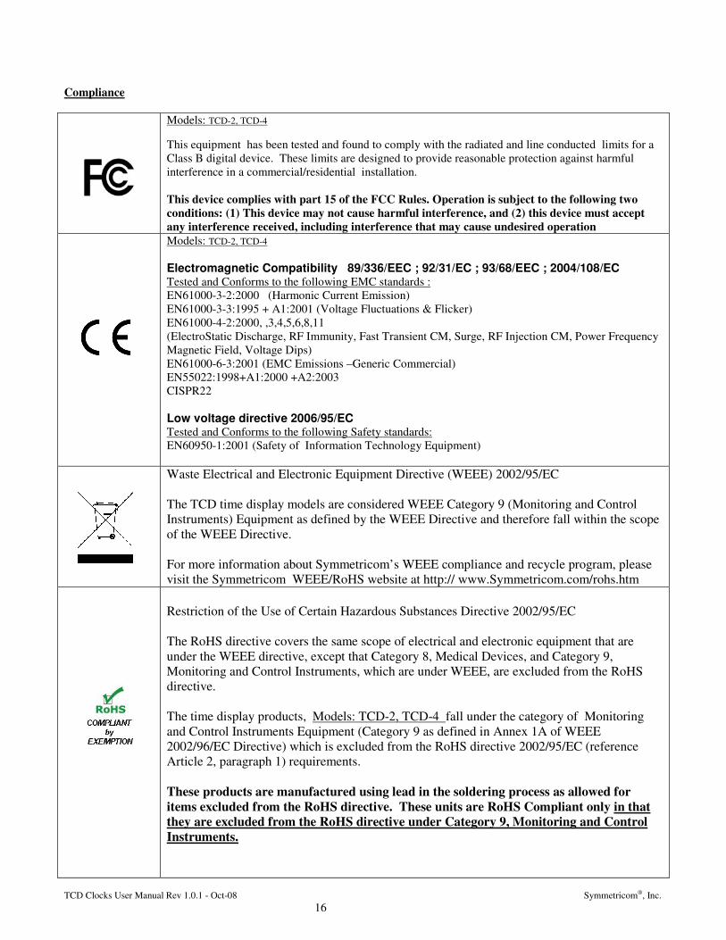
Models: TCD-2, TCD-4 This equipment has been tested and found to comply with the radiated and line conducted limits for a Class B digital device. These limits are designed to provide reasonable protection against harmful interference in a commercial/residential installation. This device complies with part 15 of the FCC Rules. Operation is subject to the following two conditions: (1) This device may not cause harmful interference, and (2) this device must accept any interference received, including interference that may cause undesired operation
Models: TCD-2, TCD-4 Electromagnetic Compatibility 89/336/EEC ; 92/31/EC ; 93/68/EEC ; 2004/108/EC Tested and Conforms to the following EMC standards : EN61000-3-2:2000 (Harmonic Current Emission) EN61000-3-3:1995 + A1:2001 (Voltage Fluctuations & Flicker) EN61000-4-2:2000, ,3,4,5,6,8,11 (ElectroStatic Discharge, RF Immunity, Fast Transient CM, Surge, RF Injection CM, Power Frequency Magnetic Field, Voltage Dips) EN61000-6-3:2001 (EMC Emissions –Generic Commercial) EN55022:1998+A1:2000 +A2:2003 CISPR22 Low voltage directive 2006/95/EC Tested and Conforms to the following Safety standards: EN60950-1:2001 (Safety of Information Technology Equipment)
Waste Electrical and Electronic Equipment Directive (WEEE) 2002/95/EC The TCD time display models are considered WEEE Category 9 (Monitoring and Control Instruments) Equipment as defined by the WEEE Directive and therefore fall within the scope of the WEEE Directive. For more information about Symmetricom’s WEEE compliance and recycle program, please visit the Symmetricom WEEE/RoHS website at http:// www.Symmetricom.com/rohs.htm
Restriction of the Use of Certain Hazardous Substances Directive 2002/95/EC The RoHS directive covers the same scope of electrical and electronic equipment that are under the WEEE directive, except that Category 8, Medical Devices, and Category 9, Monitoring and Control Instruments, which are under WEEE, are excluded from the RoHS directive. The time display products, Models: TCD-2, TCD-4 fall under the category of Monitoring and Control Instruments Equipment (Category 9 as defined in Annex 1A of WEEE 2002/96/EC Directive) which is excluded from the RoHS directive 2002/95/EC (reference Article 2, paragraph 1) requirements. These products are manufactured using lead in the soldering process as allowed for items excluded from the RoHS directive. These units are RoHS Compliant only in that they are excluded from the RoHS directive under Category 9, Monitoring and Control Instruments.

TCD Clocks User Manual Rev 1.0.1 - Oct-08 Symmetricom®, Inc. 17
Limited Warranty
Each new product manufactured by Symmetricom is warranted for defects in material or workmanship for a period of one year from date of shipment (“Limited Warranty”). Defects in material or workmanship found within that period will be replaced or repaired, at Symmetricom's option, without charge for material or labor, provided the customer returns the equipment, freight prepaid, to the Symmetricom factory under this limited warranty. Symmetricom will return the repaired equipment, freight prepaid, to the customer's facility.
Limitation of Liability
By purchasing any product from Symmetricom, the Buyer consents to and agrees that the Buyer's sole and exclusive remedy for any damages or losses incurred by the Buyer, as a result of Symmetricom's breach of its one-year Limited Warranty for defects in materials and workmanship or otherwise in connection with any claim respecting the product, shall be limited to the repair or replacement of the product or a refund of the sales price of the product. In no event shall the Buyer be entitled to recover consequential damages or any other damages of any kind or description whatsoever.
Proprietary Notice
THIS DOCUMENT, WHETHER PATENTABLE OR NON-PATENTABLE SUBJECT MATTER, EMBODIES PROPRIETARY AND CONFIDENTIAL INFORMATION. IT MAY NOT BE REPRODUCED, USED OR DISCLOSED TO OTHERS FOR ANY PURPOSE EXCEPT THAT FOR WHICH IT IS PURCHASED OR LOANED.

3750 Westwind Boulevard Santa Rosa, California 95403
Main 707.528.1230
Fax 707.527.6640 www.symmetricom.com
TT&M Division
CERTIFICATE OF VOLATILITY Date: 19 September 2008 Model: Network Time Display Part No. TCD-2 P/N 820-1448 TCD-4 P/N 820-1450 This document describes volatile and non-volatile storage media of the above noted models. Note: The below storage components are on the main controller board Atmel P/N AT89C51RC2-3CSUM 32K x 8 bit Flash, Microprocessor The remaining parts of the TCD contain no memory devices. There are no special procedures to remove information directly from the memory chips, other than to reset the unit to the Factory Defaults using the below procedure. The reset to factory default procedure is as follows: By default the TCD clock will come up and read the position of the DIP switches to determine its operational mode. Information such as time zone or DST information that has been entered via the serial port interface will not be retained after a power cycle.
1. Remove power by removing the AC power cord. 2. Reapply power by inserting the AC power cord.
Robert Mengelberg Authorized Signature Quality Engineer Title 19 September 2008 Date


