136
Advanced Design System 2011.01 - TD-SCDMA Wireless Test Benches 1 Advanced Design System 2011.01 Feburary 2011 TD-SCDMA Wireless Test Benches
Advanced Design System 2011.01 - TD-SCDMA Wireless Test Benches
1
Advanced Design System 2011.01
Feburary 2011TD-SCDMA Wireless Test Benches
Advanced Design System 2011.01 - TD-SCDMA Wireless Test Benches
2
© Agilent Technologies, Inc. 2000-20115301 Stevens Creek Blvd., Santa Clara, CA 95052 USANo part of this documentation may be reproduced in any form or by any means (includingelectronic storage and retrieval or translation into a foreign language) without prioragreement and written consent from Agilent Technologies, Inc. as governed by UnitedStates and international copyright laws.
AcknowledgmentsMentor Graphics is a trademark of Mentor Graphics Corporation in the U.S. and othercountries. Mentor products and processes are registered trademarks of Mentor GraphicsCorporation. * Calibre is a trademark of Mentor Graphics Corporation in the US and othercountries. "Microsoft®, Windows®, MS Windows®, Windows NT®, Windows 2000® andWindows Internet Explorer® are U.S. registered trademarks of Microsoft Corporation.Pentium® is a U.S. registered trademark of Intel Corporation. PostScript® and Acrobat®are trademarks of Adobe Systems Incorporated. UNIX® is a registered trademark of theOpen Group. Oracle and Java and registered trademarks of Oracle and/or its affiliates.Other names may be trademarks of their respective owners. SystemC® is a registeredtrademark of Open SystemC Initiative, Inc. in the United States and other countries and isused with permission. MATLAB® is a U.S. registered trademark of The Math Works, Inc..HiSIM2 source code, and all copyrights, trade secrets or other intellectual property rightsin and to the source code in its entirety, is owned by Hiroshima University and STARC.FLEXlm is a trademark of Globetrotter Software, Incorporated. Layout Boolean Engine byKlaas Holwerda, v1.7 http://www.xs4all.nl/~kholwerd/bool.html . FreeType Project,Copyright (c) 1996-1999 by David Turner, Robert Wilhelm, and Werner Lemberg.QuestAgent search engine (c) 2000-2002, JObjects. Motif is a trademark of the OpenSoftware Foundation. Netscape is a trademark of Netscape Communications Corporation.Netscape Portable Runtime (NSPR), Copyright (c) 1998-2003 The Mozilla Organization. Acopy of the Mozilla Public License is at http://www.mozilla.org/MPL/ . FFTW, The FastestFourier Transform in the West, Copyright (c) 1997-1999 Massachusetts Institute ofTechnology. All rights reserved.
The following third-party libraries are used by the NlogN Momentum solver:
"This program includes Metis 4.0, Copyright © 1998, Regents of the University ofMinnesota", http://www.cs.umn.edu/~metis , METIS was written by George Karypis([email protected]).
Intel@ Math Kernel Library, http://www.intel.com/software/products/mkl
SuperLU_MT version 2.0 - Copyright © 2003, The Regents of the University of California,through Lawrence Berkeley National Laboratory (subject to receipt of any requiredapprovals from U.S. Dept. of Energy). All rights reserved. SuperLU Disclaimer: THISSOFTWARE IS PROVIDED BY THE COPYRIGHT HOLDERS AND CONTRIBUTORS "AS IS"AND ANY EXPRESS OR IMPLIED WARRANTIES, INCLUDING, BUT NOT LIMITED TO, THEIMPLIED WARRANTIES OF MERCHANTABILITY AND FITNESS FOR A PARTICULAR PURPOSEARE DISCLAIMED. IN NO EVENT SHALL THE COPYRIGHT OWNER OR CONTRIBUTORS BELIABLE FOR ANY DIRECT, INDIRECT, INCIDENTAL, SPECIAL, EXEMPLARY, ORCONSEQUENTIAL DAMAGES (INCLUDING, BUT NOT LIMITED TO, PROCUREMENT OF
Advanced Design System 2011.01 - TD-SCDMA Wireless Test Benches
3
SUBSTITUTE GOODS OR SERVICES; LOSS OF USE, DATA, OR PROFITS; OR BUSINESSINTERRUPTION) HOWEVER CAUSED AND ON ANY THEORY OF LIABILITY, WHETHER INCONTRACT, STRICT LIABILITY, OR TORT (INCLUDING NEGLIGENCE OR OTHERWISE)ARISING IN ANY WAY OUT OF THE USE OF THIS SOFTWARE, EVEN IF ADVISED OF THEPOSSIBILITY OF SUCH DAMAGE.
7-zip - 7-Zip Copyright: Copyright (C) 1999-2009 Igor Pavlov. Licenses for files are:7z.dll: GNU LGPL + unRAR restriction, All other files: GNU LGPL. 7-zip License: This libraryis free software; you can redistribute it and/or modify it under the terms of the GNULesser General Public License as published by the Free Software Foundation; eitherversion 2.1 of the License, or (at your option) any later version. This library is distributedin the hope that it will be useful,but WITHOUT ANY WARRANTY; without even the impliedwarranty of MERCHANTABILITY or FITNESS FOR A PARTICULAR PURPOSE. See the GNULesser General Public License for more details. You should have received a copy of theGNU Lesser General Public License along with this library; if not, write to the FreeSoftware Foundation, Inc., 59 Temple Place, Suite 330, Boston, MA 02111-1307 USA.unRAR copyright: The decompression engine for RAR archives was developed using sourcecode of unRAR program.All copyrights to original unRAR code are owned by AlexanderRoshal. unRAR License: The unRAR sources cannot be used to re-create the RARcompression algorithm, which is proprietary. Distribution of modified unRAR sources inseparate form or as a part of other software is permitted, provided that it is clearly statedin the documentation and source comments that the code may not be used to develop aRAR (WinRAR) compatible archiver. 7-zip Availability: http://www.7-zip.org/
AMD Version 2.2 - AMD Notice: The AMD code was modified. Used by permission. AMDcopyright: AMD Version 2.2, Copyright © 2007 by Timothy A. Davis, Patrick R. Amestoy,and Iain S. Duff. All Rights Reserved. AMD License: Your use or distribution of AMD or anymodified version of AMD implies that you agree to this License. This library is freesoftware; you can redistribute it and/or modify it under the terms of the GNU LesserGeneral Public License as published by the Free Software Foundation; either version 2.1 ofthe License, or (at your option) any later version. This library is distributed in the hopethat it will be useful, but WITHOUT ANY WARRANTY; without even the implied warranty ofMERCHANTABILITY or FITNESS FOR A PARTICULAR PURPOSE. See the GNU LesserGeneral Public License for more details. You should have received a copy of the GNULesser General Public License along with this library; if not, write to the Free SoftwareFoundation, Inc., 51 Franklin St, Fifth Floor, Boston, MA 02110-1301 USA Permission ishereby granted to use or copy this program under the terms of the GNU LGPL, providedthat the Copyright, this License, and the Availability of the original version is retained onall copies.User documentation of any code that uses this code or any modified version ofthis code must cite the Copyright, this License, the Availability note, and "Used bypermission." Permission to modify the code and to distribute modified code is granted,provided the Copyright, this License, and the Availability note are retained, and a noticethat the code was modified is included. AMD Availability:http://www.cise.ufl.edu/research/sparse/amd
UMFPACK 5.0.2 - UMFPACK Notice: The UMFPACK code was modified. Used by permission.UMFPACK Copyright: UMFPACK Copyright © 1995-2006 by Timothy A. Davis. All RightsReserved. UMFPACK License: Your use or distribution of UMFPACK or any modified versionof UMFPACK implies that you agree to this License. This library is free software; you canredistribute it and/or modify it under the terms of the GNU Lesser General Public License
Advanced Design System 2011.01 - TD-SCDMA Wireless Test Benches
4
as published by the Free Software Foundation; either version 2.1 of the License, or (atyour option) any later version. This library is distributed in the hope that it will be useful,but WITHOUT ANY WARRANTY; without even the implied warranty of MERCHANTABILITYor FITNESS FOR A PARTICULAR PURPOSE. See the GNU Lesser General Public License formore details. You should have received a copy of the GNU Lesser General Public Licensealong with this library; if not, write to the Free Software Foundation, Inc., 51 Franklin St,Fifth Floor, Boston, MA 02110-1301 USA Permission is hereby granted to use or copy thisprogram under the terms of the GNU LGPL, provided that the Copyright, this License, andthe Availability of the original version is retained on all copies. User documentation of anycode that uses this code or any modified version of this code must cite the Copyright, thisLicense, the Availability note, and "Used by permission." Permission to modify the codeand to distribute modified code is granted, provided the Copyright, this License, and theAvailability note are retained, and a notice that the code was modified is included.UMFPACK Availability: http://www.cise.ufl.edu/research/sparse/umfpack UMFPACK(including versions 2.2.1 and earlier, in FORTRAN) is available athttp://www.cise.ufl.edu/research/sparse . MA38 is available in the Harwell SubroutineLibrary. This version of UMFPACK includes a modified form of COLAMD Version 2.0,originally released on Jan. 31, 2000, also available athttp://www.cise.ufl.edu/research/sparse . COLAMD V2.0 is also incorporated as a built-infunction in MATLAB version 6.1, by The MathWorks, Inc. http://www.mathworks.com .COLAMD V1.0 appears as a column-preordering in SuperLU (SuperLU is available athttp://www.netlib.org ). UMFPACK v4.0 is a built-in routine in MATLAB 6.5. UMFPACK v4.3is a built-in routine in MATLAB 7.1.
Qt Version 4.6.3 - Qt Notice: The Qt code was modified. Used by permission. Qt copyright:Qt Version 4.6.3, Copyright (c) 2010 by Nokia Corporation. All Rights Reserved. QtLicense: Your use or distribution of Qt or any modified version of Qt implies that you agreeto this License. This library is free software; you can redistribute it and/or modify it undertheterms of the GNU Lesser General Public License as published by the Free SoftwareFoundation; either version 2.1 of the License, or (at your option) any later version. Thislibrary is distributed in the hope that it will be useful,but WITHOUT ANY WARRANTY; without even the implied warranty of MERCHANTABILITYor FITNESS FOR A PARTICULAR PURPOSE. See the GNU Lesser General Public License formore details. You should have received a copy of the GNU Lesser General Public Licensealong with this library; if not, write to the Free Software Foundation, Inc., 51 Franklin St,Fifth Floor, Boston, MA 02110-1301 USA Permission is hereby granted to use or copy thisprogram under the terms of the GNU LGPL, provided that the Copyright, this License, andthe Availability of the original version is retained on all copies.Userdocumentation of any code that uses this code or any modified version of this code mustcite the Copyright, this License, the Availability note, and "Used by permission."Permission to modify the code and to distribute modified code is granted, provided theCopyright, this License, and the Availability note are retained, and a notice that the codewas modified is included. Qt Availability: http://www.qtsoftware.com/downloads PatchesApplied to Qt can be found in the installation at:$HPEESOF_DIR/prod/licenses/thirdparty/qt/patches. You may also contact BrianBuchanan at Agilent Inc. at [email protected] for more information.
The HiSIM_HV source code, and all copyrights, trade secrets or other intellectual propertyrights in and to the source code, is owned by Hiroshima University and/or STARC.
Advanced Design System 2011.01 - TD-SCDMA Wireless Test Benches
5
Errata The ADS product may contain references to "HP" or "HPEESOF" such as in filenames and directory names. The business entity formerly known as "HP EEsof" is now partof Agilent Technologies and is known as "Agilent EEsof". To avoid broken functionality andto maintain backward compatibility for our customers, we did not change all the namesand labels that contain "HP" or "HPEESOF" references.
Warranty The material contained in this document is provided "as is", and is subject tobeing changed, without notice, in future editions. Further, to the maximum extentpermitted by applicable law, Agilent disclaims all warranties, either express or implied,with regard to this documentation and any information contained herein, including but notlimited to the implied warranties of merchantability and fitness for a particular purpose.Agilent shall not be liable for errors or for incidental or consequential damages inconnection with the furnishing, use, or performance of this document or of anyinformation contained herein. Should Agilent and the user have a separate writtenagreement with warranty terms covering the material in this document that conflict withthese terms, the warranty terms in the separate agreement shall control.
Technology Licenses The hardware and/or software described in this document arefurnished under a license and may be used or copied only in accordance with the terms ofsuch license. Portions of this product include the SystemC software licensed under OpenSource terms, which are available for download at http://systemc.org/ . This software isredistributed by Agilent. The Contributors of the SystemC software provide this software"as is" and offer no warranty of any kind, express or implied, including without limitationwarranties or conditions or title and non-infringement, and implied warranties orconditions merchantability and fitness for a particular purpose. Contributors shall not beliable for any damages of any kind including without limitation direct, indirect, special,incidental and consequential damages, such as lost profits. Any provisions that differ fromthis disclaimer are offered by Agilent only.
Restricted Rights Legend U.S. Government Restricted Rights. Software and technicaldata rights granted to the federal government include only those rights customarilyprovided to end user customers. Agilent provides this customary commercial license inSoftware and technical data pursuant to FAR 12.211 (Technical Data) and 12.212(Computer Software) and, for the Department of Defense, DFARS 252.227-7015(Technical Data - Commercial Items) and DFARS 227.7202-3 (Rights in CommercialComputer Software or Computer Software Documentation).
Advanced Design System 2011.01 - TD-SCDMA Wireless Test Benches
6
Downlink Multicarrier Transmitter Test . . . . . . . . . . . . . . . . . . . . . . . . . . . . . . . . . . . . . . . . . 7 Introduction . . . . . . . . . . . . . . . . . . . . . . . . . . . . . . . . . . . . . . . . . . . . . . . . . . . . . . . . . . 8 Test Bench Basics . . . . . . . . . . . . . . . . . . . . . . . . . . . . . . . . . . . . . . . . . . . . . . . . . . . . . . 11 Test Bench Details . . . . . . . . . . . . . . . . . . . . . . . . . . . . . . . . . . . . . . . . . . . . . . . . . . . . . . 12 TDSCDMA_DnLnk_MultiCarrier_TX . . . . . . . . . . . . . . . . . . . . . . . . . . . . . . . . . . . . . . . . . 14 Setting Parameters . . . . . . . . . . . . . . . . . . . . . . . . . . . . . . . . . . . . . . . . . . . . . . . . . . . . . 17 Simulation Measurement Displays . . . . . . . . . . . . . . . . . . . . . . . . . . . . . . . . . . . . . . . . . . . 24 Baseline Performance . . . . . . . . . . . . . . . . . . . . . . . . . . . . . . . . . . . . . . . . . . . . . . . . . . . 27 References . . . . . . . . . . . . . . . . . . . . . . . . . . . . . . . . . . . . . . . . . . . . . . . . . . . . . . . . . . . 28
Downlink Receiver Adjacent Channel Selectivity Test . . . . . . . . . . . . . . . . . . . . . . . . . . . . . . . 29 Introduction . . . . . . . . . . . . . . . . . . . . . . . . . . . . . . . . . . . . . . . . . . . . . . . . . . . . . . . . . . 30 Test Bench Basics . . . . . . . . . . . . . . . . . . . . . . . . . . . . . . . . . . . . . . . . . . . . . . . . . . . . . . 32 Test Bench Details . . . . . . . . . . . . . . . . . . . . . . . . . . . . . . . . . . . . . . . . . . . . . . . . . . . . . . 33 TDSCDMA_DnLnk_RX_ACS . . . . . . . . . . . . . . . . . . . . . . . . . . . . . . . . . . . . . . . . . . . . . . . 35 Setting Parameters . . . . . . . . . . . . . . . . . . . . . . . . . . . . . . . . . . . . . . . . . . . . . . . . . . . . . 37 Simulation Measurement Displays . . . . . . . . . . . . . . . . . . . . . . . . . . . . . . . . . . . . . . . . . . . 40 Baseline Performance . . . . . . . . . . . . . . . . . . . . . . . . . . . . . . . . . . . . . . . . . . . . . . . . . . . 41 References . . . . . . . . . . . . . . . . . . . . . . . . . . . . . . . . . . . . . . . . . . . . . . . . . . . . . . . . . . . 42
Downlink Transmitter Test . . . . . . . . . . . . . . . . . . . . . . . . . . . . . . . . . . . . . . . . . . . . . . . . . . 43 Introduction . . . . . . . . . . . . . . . . . . . . . . . . . . . . . . . . . . . . . . . . . . . . . . . . . . . . . . . . . . 44 Test Bench Basics . . . . . . . . . . . . . . . . . . . . . . . . . . . . . . . . . . . . . . . . . . . . . . . . . . . . . . 47 Test Bench Details . . . . . . . . . . . . . . . . . . . . . . . . . . . . . . . . . . . . . . . . . . . . . . . . . . . . . . 48 TDSCDMA_DnLnk_TX . . . . . . . . . . . . . . . . . . . . . . . . . . . . . . . . . . . . . . . . . . . . . . . . . . . . 50 Setting Parameters . . . . . . . . . . . . . . . . . . . . . . . . . . . . . . . . . . . . . . . . . . . . . . . . . . . . . 54 Simulation Measurement Displays . . . . . . . . . . . . . . . . . . . . . . . . . . . . . . . . . . . . . . . . . . . 65 Baseline Performance . . . . . . . . . . . . . . . . . . . . . . . . . . . . . . . . . . . . . . . . . . . . . . . . . . . 75 References for Downlink Transmitter Test . . . . . . . . . . . . . . . . . . . . . . . . . . . . . . . . . . . . . 76
Measurement Results for Expressions for TD-SCDMA Wireless Test Benches . . . . . . . . . . . . . . . 77 RF DUT Limitations for TD-SCDMA Wireless Test Benches . . . . . . . . . . . . . . . . . . . . . . . . . . . . 84 Uplink Receiver Sensitivity Test . . . . . . . . . . . . . . . . . . . . . . . . . . . . . . . . . . . . . . . . . . . . . . 88
Introduction . . . . . . . . . . . . . . . . . . . . . . . . . . . . . . . . . . . . . . . . . . . . . . . . . . . . . . . . . . 89 Test Bench Basics . . . . . . . . . . . . . . . . . . . . . . . . . . . . . . . . . . . . . . . . . . . . . . . . . . . . . . 91 Test Bench Details . . . . . . . . . . . . . . . . . . . . . . . . . . . . . . . . . . . . . . . . . . . . . . . . . . . . . . 92 TDSCDMA_UpLnk_RX_Sensitivity . . . . . . . . . . . . . . . . . . . . . . . . . . . . . . . . . . . . . . . . . . 94 Setting Parameters . . . . . . . . . . . . . . . . . . . . . . . . . . . . . . . . . . . . . . . . . . . . . . . . . . . . . 97 Simulation Measurement Displays . . . . . . . . . . . . . . . . . . . . . . . . . . . . . . . . . . . . . . . . . . . 100 Baseline Performance . . . . . . . . . . . . . . . . . . . . . . . . . . . . . . . . . . . . . . . . . . . . . . . . . . . 102 References . . . . . . . . . . . . . . . . . . . . . . . . . . . . . . . . . . . . . . . . . . . . . . . . . . . . . . . . . . . 103
Uplink Transmitter Test . . . . . . . . . . . . . . . . . . . . . . . . . . . . . . . . . . . . . . . . . . . . . . . . . . . . 104 Introduction . . . . . . . . . . . . . . . . . . . . . . . . . . . . . . . . . . . . . . . . . . . . . . . . . . . . . . . . . . 105 Test Bench Basics . . . . . . . . . . . . . . . . . . . . . . . . . . . . . . . . . . . . . . . . . . . . . . . . . . . . . . 107 Test Bench Details . . . . . . . . . . . . . . . . . . . . . . . . . . . . . . . . . . . . . . . . . . . . . . . . . . . . . . 108 TDSCDMA_UpLnk_TX . . . . . . . . . . . . . . . . . . . . . . . . . . . . . . . . . . . . . . . . . . . . . . . . . . . . 110 Setting Parameters . . . . . . . . . . . . . . . . . . . . . . . . . . . . . . . . . . . . . . . . . . . . . . . . . . . . . 114 Simulation Measurement Displays . . . . . . . . . . . . . . . . . . . . . . . . . . . . . . . . . . . . . . . . . . . 125 Baseline Performance . . . . . . . . . . . . . . . . . . . . . . . . . . . . . . . . . . . . . . . . . . . . . . . . . . . 135 References for Uplink Transmitter Test . . . . . . . . . . . . . . . . . . . . . . . . . . . . . . . . . . . . . . . 136
Advanced Design System 2011.01 - TD-SCDMA Wireless Test Benches
7
Downlink Multicarrier Transmitter Test
Advanced Design System 2011.01 - TD-SCDMA Wireless Test Benches
8
IntroductionTDSCDMA_DnLnk_MultiCarrier_TX test bench for TD-SCDMA downlink (base station touser equipment) transmitter testing provides a way for users to connect to an RF circuitdevice under test (RF DUT) and determine its performance by activating variousmeasurements. This test bench provides signal measurements for power (including CCDF)and spectrum.
The signal is designed according to 3GPP TS 25 (Release 4).
This TD-SCDMA signal source is compatible with Agilent Signal Studio signal sourcesoftware option 411. Details regarding Signal Studio for TD-SCDMA are included at thewebsite http://www.agilent.com/find/signalstudio .
The RF DUT output signal can be sent to an Agilent ESG RF signal generator.
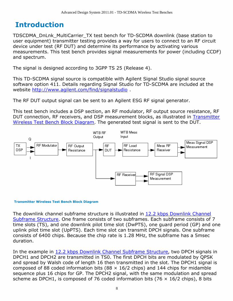
This test bench includes a DSP section, an RF modulator, RF output source resistance, RFDUT connection, RF receivers, and DSP measurement blocks, as illustrated in TransmitterWireless Test Bench Block Diagram. The generated test signal is sent to the DUT.
Transmitter Wireless Test Bench Block Diagram
The downlink channel subframe structure is illustrated in 12.2 kbps Downlink ChannelSubframe Structure. One frame consists of two subframes. Each subframe consists of 7time slots (TS), and one downlink pilot time slot (DwPTS), one guard period (GP) and oneuplink pilot time slot (UpPTS). Each time slot can transmit DPCH signals. One subframeconsists of 6400 chips. Because the chip rate is 1.28 MHz, the subframe has a 5msecduration.
In the example in 12.2 kbps Downlink Channel Subframe Structure, two DPCH signals inDPCH1 and DPCH2 are transmitted in TS0. The first DPCH bits are modulated by QPSKand spread by Walsh code of length 16 then transmitted in the slot. The DPCH1 signal iscomposed of 88 coded information bits (88 × 16/2 chips) and 144 chips for midamblesequence plus 16 chips for GP. The DPCH2 signal, with the same modulation and spreadscheme as DPCH1, is composed of 76 coded information bits (76 × 16/2 chips), 8 bits

Advanced Design System 2011.01 - TD-SCDMA Wireless Test Benches
9
(8 × 16/2 chips) for transport format combination indicator (TFCI), 144 chips formidamble sequence, 4 bits (4 × 16/2 chips) for transmitter power control andsynchronization shift (TPC and SS) plus 16 chips for GP. The total chips for the subframeis composed of 7 time slots plus 96 chips for DwPTS, 96 chips for GP and 160 chips forUpPTS and summarized as (88 × 8+144+16) × 7+160+96 × 2=6400 chips.
12.2 kbps Downlink Channel Subframe Structure
TD-SCDMA RF power delivered into a matched load is the average power delivered in theselected time slot TS6 in the TD-SCDMA subframe. RF Signal Downlink Envelope showsthe RF envelope for an output signal with 10 dBm power.
RF Signal Downlink Envelope

Advanced Design System 2011.01 - TD-SCDMA Wireless Test Benches
10
Advanced Design System 2011.01 - TD-SCDMA Wireless Test Benches
11
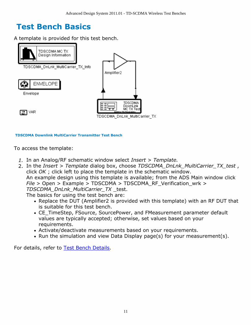
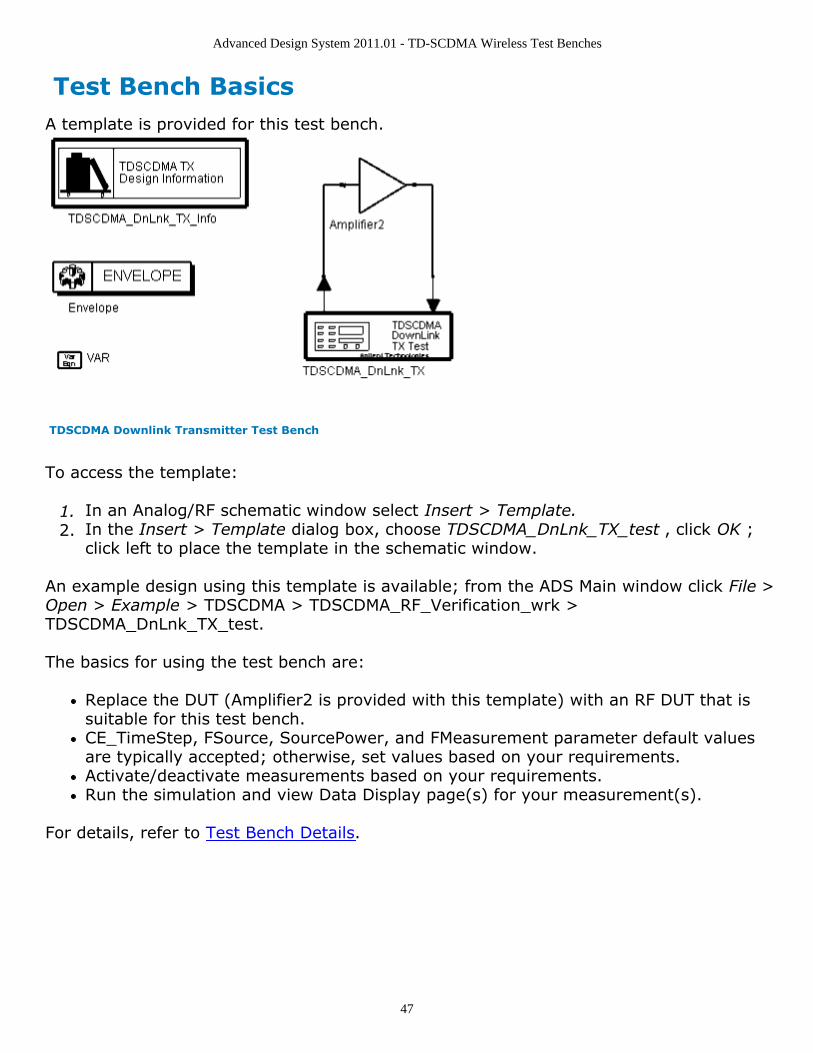
Test Bench BasicsA template is provided for this test bench.
TDSCDMA Downlink MultiCarrier Transmitter Test Bench
To access the template:
In an Analog/RF schematic window select Insert > Template.1.In the Insert > Template dialog box, choose TDSCDMA_DnLnk_MultiCarrier_TX_test ,2.click OK ; click left to place the template in the schematic window.An example design using this template is available; from the ADS Main window clickFile > Open > Example > TDSCDMA > TDSCDMA_RF_Verification_wrk >TDSCDMA_DnLnk_MultiCarrier_TX _test.The basics for using the test bench are:
Replace the DUT (Amplifier2 is provided with this template) with an RF DUT thatis suitable for this test bench.CE_TimeStep, FSource, SourcePower, and FMeasurement parameter defaultvalues are typically accepted; otherwise, set values based on yourrequirements.Activate/deactivate measurements based on your requirements.Run the simulation and view Data Display page(s) for your measurement(s).
For details, refer to Test Bench Details.
Advanced Design System 2011.01 - TD-SCDMA Wireless Test Benches
12
Test Bench DetailsThe following sections provide details for setting up a test bench, setting measurementparameters for more control of the test bench, simulation measurement displays, andbaseline performance.
Open and use the TDSCDMA_DnLnk_MultiCarrier_TX_test template:
In an Analog/RF schematic window select Insert > Template.1.In the Insert > Template dialog box, choose TDSCDMA_DnLnk_MultiCarrier_TX_test ,2.click OK ; click left to place the template in the schematic window.
The test bench setup is detailed here.
Replace the DUT (Amplifier2 is provided with this template) with an RF DUT that is1.suitable for this test bench.For information regarding using certain types of DUTs, see RF DUT Limitations forTD-SCDMA Wireless Test Benches (adswtbtds).Set the Required Parameters2.
NoteRefer to TDSCDMA_DnLnk_MultiCarrier_TX (adswtbtds) for a complete list of parameters for thistest bench.
Generally, default values can be accepted; otherwise, values can be changed by theuser as needed.
Set CE_TimeStep.Cosimulation occurs between the test bench (using ADS Ptolemy Data Flowsimulation technology) and the DUT (using Circuit Envelope simulationtechnology). Each technology requires its own simulation time step with time-step coordination occurring in the interface between the technologies.CE_TimeStep defines the Circuit Envelope simulation time step to be used withthis DUT. The CE_TimeStep must be set to a value equal to or a submultiple of(less than) WTB_TimeStep; otherwise, simulation will stop and an errormessage will be displayed.Note that WTB_TimeStep is not user-settable. Its value is derived from othertest bench parameter values; with default settings WTB_TimeStep= 48.828125nsec. The value is displayed in the Data Display pages as TimeStep.WTB_TimeStep = 1/(ChipRate × SamplesPerChip)whereChipRate is 1.28MHzSamplesPerChip is the number of samples per chipSet FSource, SourcePower, and FMeasurement.
FSource defines the RF frequency for the TD-SCDMA signal input to the RFDUT.SourcePower defines the power level for FSource. SourcePower is definedas the average power during the non-idle time of the TD-SCDMA signalsegment.FMeasurement defines the TDSCDMA RF frequency output from the RF DUT
Advanced Design System 2011.01 - TD-SCDMA Wireless Test Benches
13
to be measured.Activate/deactivate ( YES / NO ) test bench measurements (refer to3.TDSCDMA_DnLnk_MultiCarrier_TX (adswtbtds)). At least one measurement must beenabled from the measurement list:
PowerMeasurementSpectrumMeasurement
More control of the test bench can be achieved by setting parameters on the Basic4.Parameters , Signal Parameters , and measurement categories for each activatedmeasurement. For details, refer to Setting Parameters (adswtbtds).The RF modulator (shown in the block diagram in Transmitter Wireless Test Bench5.Block Diagram) uses FSource, SourcePower ( Required Parameters ),MirrorSourceSpectrum ( Basic Parameters) , GainImbalance, PhaseImbalance,I_OriginOffset, Q_OriginOffset, and IQ_Rotation ( Signal Parameters ).The RF output resistance uses SourceR, SourceTemp, and EnableSourceNoise ( BasicParameters ). The RF output signal source has a 50-ohm (default) output resistancedefined by SourceR.RF output (and input to the RF DUT) is at the frequency specified (FSource), with thespecified source resistance (SourceR) and with power (SourcePower) delivered into amatched load of resistance SourceR. The RF signal has additive Gaussian noise powerset by resistor temperature (SourceTemp) (when EnableSourceNoise=YES).Note that the Meas_in point of the test bench provides a resistive load to the RF DUTset by the MeasR value (50-ohm default) ( Basic Parameters ).The Meas signal contains linear and nonlinear signal distortions and time delaysassociated with the RF DUT input to output characteristics.The TX DSP block (shown in the block diagram in Transmitter Wireless Test BenchBlock Diagram) uses other Signal Parameters . More control of Circuit Envelope analysis can be achieved by setting Envelope6.controller parameters. These settings include Enable Fast Cosim, which may speedthe RF DUT simulation more than 10×. Setting these simulation options is describedin Setting Fast Comsimulation Parameters and Setting Circuit Envelope AnalysisParameters in the Wireless Test Bench Simulation documentation.After running a simulation, results will appear in a Data Display window for the7.measurement. Simulation Measurement Displays (adswtbtds) describes results foreach measurement. For general WTB Data Display details refer to Viewing WTBAnalysis Results (adswtbsim).
Advanced Design System 2011.01 - TD-SCDMA Wireless Test Benches
14
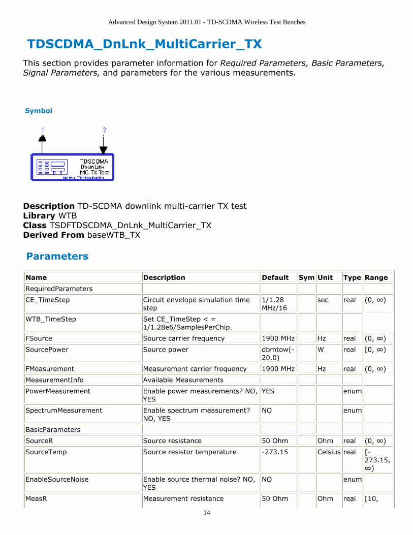
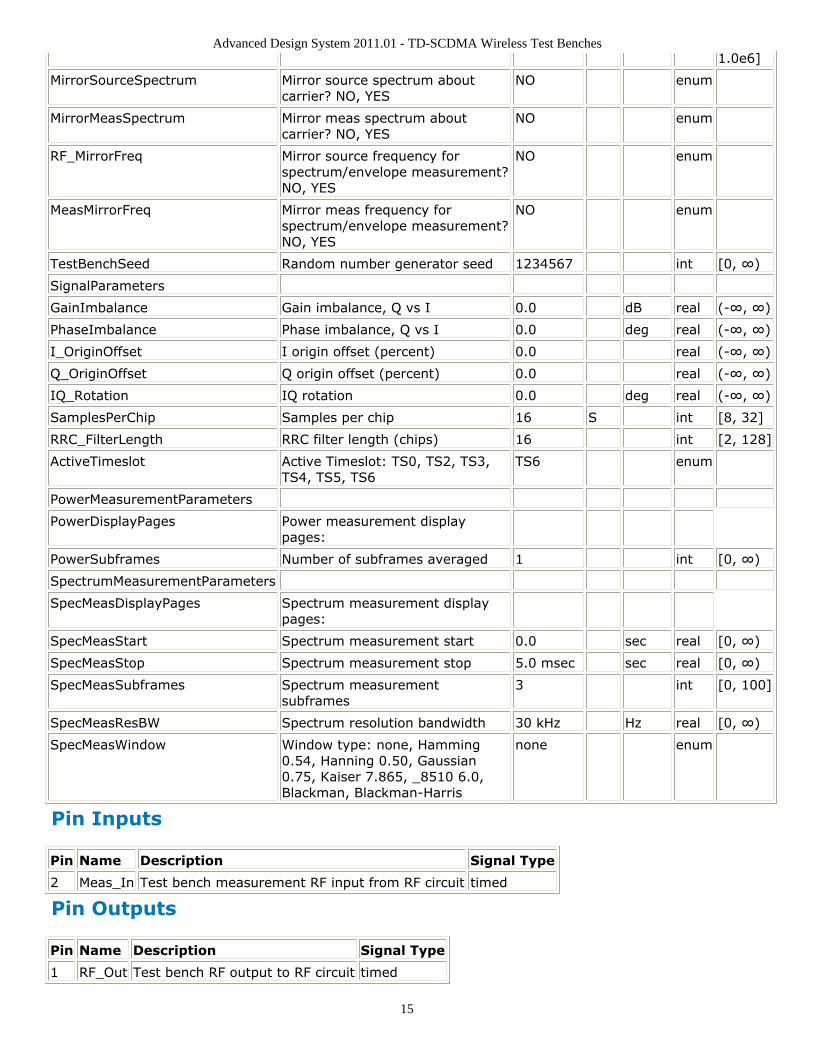
TDSCDMA_DnLnk_MultiCarrier_TX This section provides parameter information for Required Parameters, Basic Parameters,Signal Parameters, and parameters for the various measurements.
Symbol
Description TD-SCDMA downlink multi-carrier TX testLibrary WTBClass TSDFTDSCDMA_DnLnk_MultiCarrier_TXDerived From baseWTB_TX
Parameters
Name Description Default Sym Unit Type Range
RequiredParameters
CE_TimeStep Circuit envelope simulation timestep
1/1.28MHz/16
sec real (0, ∞)
WTB_TimeStep Set CE_TimeStep < =1/1.28e6/SamplesPerChip.
FSource Source carrier frequency 1900 MHz Hz real (0, ∞)
SourcePower Source power dbmtow(-20.0)
W real [0, ∞)
FMeasurement Measurement carrier frequency 1900 MHz Hz real (0, ∞)
MeasurementInfo Available Measurements
PowerMeasurement Enable power measurements? NO,YES
YES enum
SpectrumMeasurement Enable spectrum measurement?NO, YES
NO enum
BasicParameters
SourceR Source resistance 50 Ohm Ohm real (0, ∞)
SourceTemp Source resistor temperature -273.15 Celsius real [-273.15,∞)
EnableSourceNoise Enable source thermal noise? NO,YES
NO enum
MeasR Measurement resistance 50 Ohm Ohm real [10,
Advanced Design System 2011.01 - TD-SCDMA Wireless Test Benches
15
1.0e6]
MirrorSourceSpectrum Mirror source spectrum aboutcarrier? NO, YES
NO enum
MirrorMeasSpectrum Mirror meas spectrum aboutcarrier? NO, YES
NO enum
RF_MirrorFreq Mirror source frequency forspectrum/envelope measurement?NO, YES
NO enum
MeasMirrorFreq Mirror meas frequency forspectrum/envelope measurement?NO, YES
NO enum
TestBenchSeed Random number generator seed 1234567 int [0, ∞)
SignalParameters
GainImbalance Gain imbalance, Q vs I 0.0 dB real (-∞, ∞)
PhaseImbalance Phase imbalance, Q vs I 0.0 deg real (-∞, ∞)
I_OriginOffset I origin offset (percent) 0.0 real (-∞, ∞)
Q_OriginOffset Q origin offset (percent) 0.0 real (-∞, ∞)
IQ_Rotation IQ rotation 0.0 deg real (-∞, ∞)
SamplesPerChip Samples per chip 16 S int [8, 32]
RRC_FilterLength RRC filter length (chips) 16 int [2, 128]
ActiveTimeslot Active Timeslot: TS0, TS2, TS3,TS4, TS5, TS6
TS6 enum
PowerMeasurementParameters
PowerDisplayPages Power measurement displaypages:
PowerSubframes Number of subframes averaged 1 int [0, ∞)
SpectrumMeasurementParameters
SpecMeasDisplayPages Spectrum measurement displaypages:
SpecMeasStart Spectrum measurement start 0.0 sec real [0, ∞)
SpecMeasStop Spectrum measurement stop 5.0 msec sec real [0, ∞)
SpecMeasSubframes Spectrum measurementsubframes
3 int [0, 100]
SpecMeasResBW Spectrum resolution bandwidth 30 kHz Hz real [0, ∞)
SpecMeasWindow Window type: none, Hamming0.54, Hanning 0.50, Gaussian0.75, Kaiser 7.865, _8510 6.0,Blackman, Blackman-Harris
none enum
Pin Inputs
Pin Name Description Signal Type
2 Meas_In Test bench measurement RF input from RF circuit timed
Pin Outputs
Pin Name Description Signal Type
1 RF_Out Test bench RF output to RF circuit timed

Advanced Design System 2011.01 - TD-SCDMA Wireless Test Benches
16
Advanced Design System 2011.01 - TD-SCDMA Wireless Test Benches
17
Setting ParametersMore control of the test bench can be achieved by setting parameters in the BasicParameters, Signal Parameters, and measurement categories for the activatedmeasurements.
NoteFor required parameter information, see Set the Required Parameters (adswtbtds).
Basic Parameters
SourceR is the RF output source resistance.1.SourceTemp is the RF output source resistance temperature (oC) and sets noise2.density in the RF output signal to (k(SourceTemp+273.15)) Watts/Hz, where k isBoltzmann's constant.EnableSourceNoise, when set to NO disables the SourceTemp and effectively sets it3.to -273.15oC (0 Kelvin). When set to YES, the noise density due to SourceTemp isenabled.MeasR defines the load resistance for the RF DUT output Meas signal into the test4.bench. This resistance loads the RF DUT output; it is also the reference resistance forMeas signal power measurements.MirrorSourceSpectrum is used to invert the polarity of the Q envelope of the5.generated RF signal before it is sent to the RF DUT. Depending on the configurationand number of mixers in an RF transmitter, the signal at the input of the DUT mayneed to be mirrored. If such an RF signal is desired, set this parameter to YES.MirrorMeasSpectrum is used to invert the polarity of the Q envelope in the Meas_in6.RF signal input to the test bench (and output from the RF DUT). Depending on theconfiguration and number of mixers in the RF DUT, the signal at its output may bemirrored compared to the signal generated by the signal source (before any mirroringis done because of the MirrorSourceSpectrum setting). Proper demodulation andmeasurement of the RF DUT output signal requires that its RF envelope is notmirrored compared to the signal generated by the signal source (before any mirroringis done because of the MirrorSourceSpectrum setting). If the Meas_in RF signal ismirrored, set this parameter to YES. Proper setting of this parameter is required formeasurements on the Meas_in signal in TX test benches (EVM, Constellation, CDP,PCDE) and results in measurement on a signal with no spectrum mirroring.TestBenchSeed is an integer used to seed the random number generator used with7.the test bench. This value is used by all test bench random number generators,except those RF DUT components that use their own specific seed parameter.TestBenchSeed initializes the random number generation. The same seed valueproduces the same random results, thereby giving you predictable simulation results.To generate repeatable random output from simulation to simulation, use anypositive seed value. If you want the output to be truly random, enter the seed valueof 0.RF_MirrorFreq is used to invert the polarity of the Q envelope in the RF_out RF signal8.for RF envelope, ppectrum, ACLR, and occupied bandwidth measurements.
Advanced Design System 2011.01 - TD-SCDMA Wireless Test Benches
18
RF_MirrorFreq is typically set by the user to NO when MirrorSourceSpectrum = NO;RF_MirrorFreq is typically set by the user to YES when MirrorSourceSpectrum = YES.Both settings result in viewing the RF_out signal with no spectrum mirroring. Othersettings by the user result in RF_out signal for RF_Envelope and Spectrummeasurements with spectrum mirroring.MeasMirrorFreq is used to invert the polarity of the Q envelope in the Meas_in RF9.signal for the RF envelope, spectrum, ACLR, and occupied bandwidth measurements.MeasMirrorFreq is typically set to NO by the user when the combination of theMirrorSourceSpectrum value and any signal mirroring in the users RF DUT results inno spectrum mirroring in the Meas_in signal. MeasMirrorFreq is typically set to YESby the user when the combination of the MirrorSourceSpectrum and RF DUT resultsin spectrum mirroring in the Meas_in signal.Other settings result in Meas_in signal for RF_Envelope and Spectrum measurementswith spectrum mirroring. The MirrorMeasSpectrum parameter setting has no impacton the setting or use of the MeasMirrorFreq parameter.
Signal Parameters
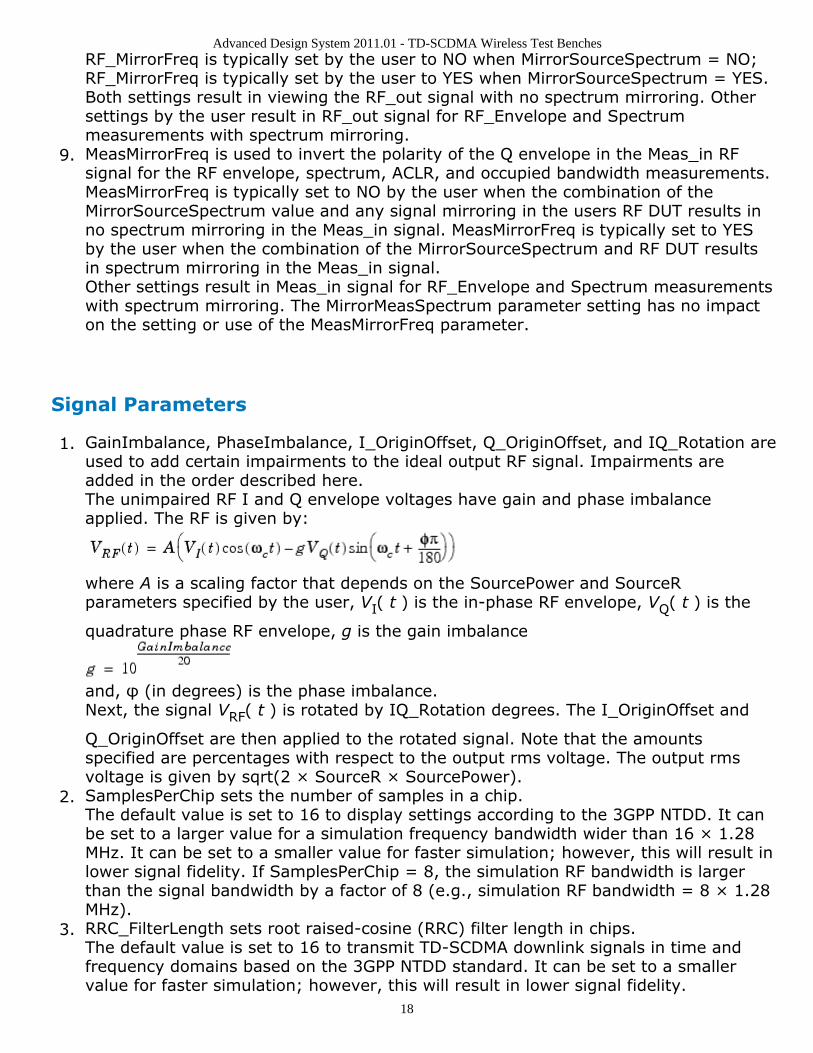
GainImbalance, PhaseImbalance, I_OriginOffset, Q_OriginOffset, and IQ_Rotation are1.used to add certain impairments to the ideal output RF signal. Impairments areadded in the order described here.The unimpaired RF I and Q envelope voltages have gain and phase imbalanceapplied. The RF is given by:
where A is a scaling factor that depends on the SourcePower and SourceRparameters specified by the user, VI( t ) is the in-phase RF envelope, VQ( t ) is the
quadrature phase RF envelope, g is the gain imbalance
and, φ (in degrees) is the phase imbalance.Next, the signal VRF( t ) is rotated by IQ_Rotation degrees. The I_OriginOffset and
Q_OriginOffset are then applied to the rotated signal. Note that the amountsspecified are percentages with respect to the output rms voltage. The output rmsvoltage is given by sqrt(2 × SourceR × SourcePower).SamplesPerChip sets the number of samples in a chip.2.The default value is set to 16 to display settings according to the 3GPP NTDD. It canbe set to a larger value for a simulation frequency bandwidth wider than 16 × 1.28MHz. It can be set to a smaller value for faster simulation; however, this will result inlower signal fidelity. If SamplesPerChip = 8, the simulation RF bandwidth is largerthan the signal bandwidth by a factor of 8 (e.g., simulation RF bandwidth = 8 × 1.28MHz).RRC_FilterLength sets root raised-cosine (RRC) filter length in chips.3.The default value is set to 16 to transmit TD-SCDMA downlink signals in time andfrequency domains based on the 3GPP NTDD standard. It can be set to a smallervalue for faster simulation; however, this will result in lower signal fidelity.
Advanced Design System 2011.01 - TD-SCDMA Wireless Test Benches
19
ActiveTimeslot specifies which slot signal in the subframe will be transmitted.4.Referring to 12.2 kbps Downlink Channel Subframe Structure (adswtbtds), whenActiveTimeslot=0, TS0 is used.
Power Measurement Parameters
PowerDisplayPages provides Data Display page information for this measurement. It1.cannot be changed by the user.PowerSubframes sets the number of subframes over which data will be collected.2.The measurement start time is the time when the first subframe is detected in the3.measured RF signal. Automatic synchronization by the measurement model avoidsany start-up transient in the Constellation plots. The measurement stop time is thisstart time plus PowerSubframes × SubframeTime. SubframeTime is described in TestBench Variables for Data Displays.
Spectrum Measurement Parameters
The Spectrum measurement calculates the spectrum of the input signal. Averaging thespectrum over multiple subframes can be enabled as described in this section.
This measurement is not affected by the MirrorMeasSpectrum parameter. To applyspectrum mirroring to the measured RF_out signal, set RF_MirrorFreq = YES; to applyspectrum mirroring to the measured Meas_in signal, set MeasMirrorFreq = YES.
In the following, TimeStep denotes the simulation time step and FMeasurement denotesthe measured RF signal characterization frequency.
The measurement outputs the complex amplitude voltage values at the frequencies1.of the spectral tones. It does not output the power at the frequencies of the spectraltones. However, one can calculate and display the power spectrum as well as themagnitude and phase spectrum by using the dBm, mag, and phase functions of thedata display window.Note that the dBm function assumes a 50-ohm reference resistance; if a differentmeasurement was used in the test bench, its value can be specified as a secondargument to the dBm function, for example, dBm(SpecMeas, Meas_RefR) whereSpecMeas is the instance name of the spectrum measurement and Meas_RefR is theresistive load used.By default, the displayed spectrum extends from FMeasurement - 1/(2×TimeStep) Hzto FMeasurement + 1/(2×TimeStep) Hz. When FMeasurement < 1/(2×TimeStep),the default spectrum extends to negative frequencies. The spectral content at thesenegative frequencies is conjugated, mirrored, and added to the spectral content ofthe closest positive frequency. The negative frequency tones are then displayed onthe positive frequency axis as would happen in an RF spectrum analyzermeasurement instrument. This process may introduce an error in the displayedfrequency for the mirrored tones. The absolute error introduced is less than
Advanced Design System 2011.01 - TD-SCDMA Wireless Test Benches
20
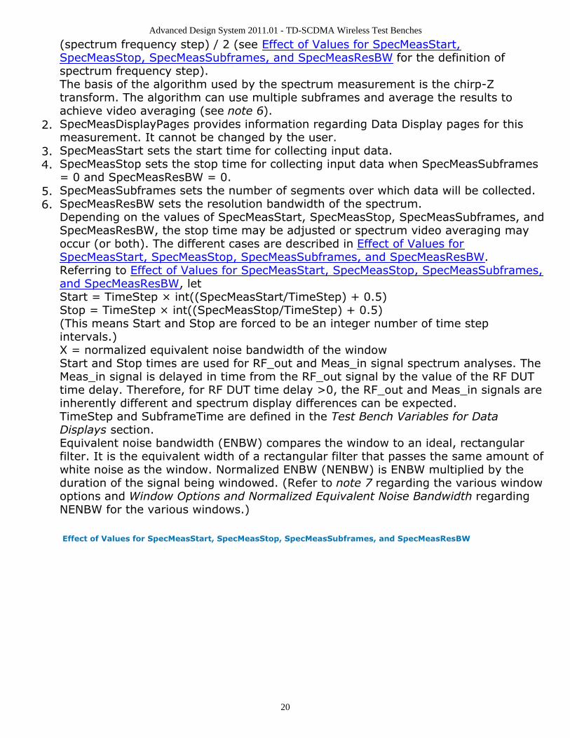
(spectrum frequency step) / 2 (see Effect of Values for SpecMeasStart,SpecMeasStop, SpecMeasSubframes, and SpecMeasResBW for the definition ofspectrum frequency step).The basis of the algorithm used by the spectrum measurement is the chirp-Ztransform. The algorithm can use multiple subframes and average the results toachieve video averaging (see note 6).SpecMeasDisplayPages provides information regarding Data Display pages for this2.measurement. It cannot be changed by the user.SpecMeasStart sets the start time for collecting input data.3.SpecMeasStop sets the stop time for collecting input data when SpecMeasSubframes4.= 0 and SpecMeasResBW = 0.SpecMeasSubframes sets the number of segments over which data will be collected.5.SpecMeasResBW sets the resolution bandwidth of the spectrum.6.Depending on the values of SpecMeasStart, SpecMeasStop, SpecMeasSubframes, andSpecMeasResBW, the stop time may be adjusted or spectrum video averaging mayoccur (or both). The different cases are described in Effect of Values forSpecMeasStart, SpecMeasStop, SpecMeasSubframes, and SpecMeasResBW.Referring to Effect of Values for SpecMeasStart, SpecMeasStop, SpecMeasSubframes,and SpecMeasResBW, letStart = TimeStep × int((SpecMeasStart/TimeStep) + 0.5)Stop = TimeStep × int((SpecMeasStop/TimeStep) + 0.5)(This means Start and Stop are forced to be an integer number of time stepintervals.)X = normalized equivalent noise bandwidth of the windowStart and Stop times are used for RF_out and Meas_in signal spectrum analyses. TheMeas_in signal is delayed in time from the RF_out signal by the value of the RF DUTtime delay. Therefore, for RF DUT time delay >0, the RF_out and Meas_in signals areinherently different and spectrum display differences can be expected.TimeStep and SubframeTime are defined in the Test Bench Variables for DataDisplays section.Equivalent noise bandwidth (ENBW) compares the window to an ideal, rectangularfilter. It is the equivalent width of a rectangular filter that passes the same amount ofwhite noise as the window. Normalized ENBW (NENBW) is ENBW multiplied by theduration of the signal being windowed. (Refer to note 7 regarding the various windowoptions and Window Options and Normalized Equivalent Noise Bandwidth regardingNENBW for the various windows.)
Effect of Values for SpecMeasStart, SpecMeasStop, SpecMeasSubframes, and SpecMeasResBW
Advanced Design System 2011.01 - TD-SCDMA Wireless Test Benches
21
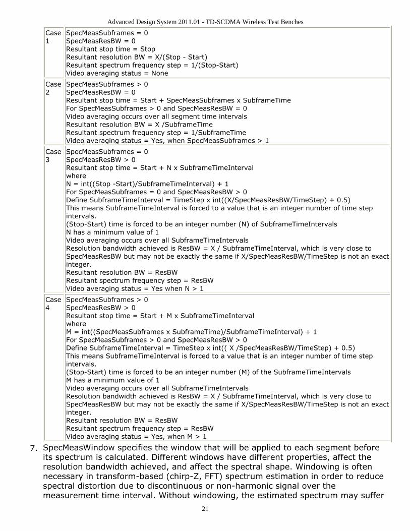
Case1
SpecMeasSubframes = 0SpecMeasResBW = 0Resultant stop time = StopResultant resolution BW = X/(Stop - Start)Resultant spectrum frequency step = 1/(Stop-Start)Video averaging status = None
Case2
SpecMeasSubframes > 0SpecMeasResBW = 0Resultant stop time = Start + SpecMeasSubframes x SubframeTimeFor SpecMeasSubframes > 0 and SpecMeasResBW = 0Video averaging occurs over all segment time intervalsResultant resolution BW = X /SubframeTimeResultant spectrum frequency step = 1/SubframeTimeVideo averaging status = Yes, when SpecMeasSubframes > 1
Case3
SpecMeasSubframes = 0SpecMeasResBW > 0Resultant stop time = Start + N x SubframeTimeIntervalwhereN = int((Stop -Start)/SubframeTimeInterval) + 1For SpecMeasSubframes = 0 and SpecMeasResBW > 0Define SubframeTimeInterval = TimeStep x int((X/SpecMeasResBW/TimeStep) + 0.5)This means SubframeTimeInterval is forced to a value that is an integer number of time stepintervals.(Stop-Start) time is forced to be an integer number (N) of SubframeTimeIntervalsN has a minimum value of 1Video averaging occurs over all SubframeTimeIntervalsResolution bandwidth achieved is ResBW = X / SubframeTimeInterval, which is very close toSpecMeasResBW but may not be exactly the same if X/SpecMeasResBW/TimeStep is not an exactinteger.Resultant resolution BW = ResBWResultant spectrum frequency step = ResBWVideo averaging status = Yes when N > 1
Case4
SpecMeasSubframes > 0SpecMeasResBW > 0Resultant stop time = Start + M x SubframeTimeIntervalwhereM = int((SpecMeasSubframes x SubframeTime)/SubframeTimeInterval) + 1For SpecMeasSubframes > 0 and SpecMeasResBW > 0Define SubframeTimeInterval = TimeStep x int(( X /SpecMeasResBW/TimeStep) + 0.5)This means SubframeTimeInterval is forced to a value that is an integer number of time stepintervals.(Stop-Start) time is forced to be an integer number (M) of the SubframeTimeIntervalsM has a minimum value of 1Video averaging occurs over all SubframeTimeIntervalsResolution bandwidth achieved is ResBW = X / SubframeTimeInterval, which is very close toSpecMeasResBW but may not be exactly the same if X/SpecMeasResBW/TimeStep is not an exactinteger.Resultant resolution BW = ResBWResultant spectrum frequency step = ResBWVideo averaging status = Yes, when M > 1
SpecMeasWindow specifies the window that will be applied to each segment before7.its spectrum is calculated. Different windows have different properties, affect theresolution bandwidth achieved, and affect the spectral shape. Windowing is oftennecessary in transform-based (chirp-Z, FFT) spectrum estimation in order to reducespectral distortion due to discontinuous or non-harmonic signal over themeasurement time interval. Without windowing, the estimated spectrum may suffer

Advanced Design System 2011.01 - TD-SCDMA Wireless Test Benches
22
from spectral leakage that can cause misleading measurements or masking of weaksignal spectral detail by spurious artifacts.The windowing of a signal in time has the effect of changing its power. The spectrummeasurement compensates for this and the spectrum is normalized so that the powercontained in it is the same as the power of the input signal.Window Type Definitions:
none
where N is the window sizeHamming 0.54
where N is the window sizeHanning 0.50
where N is the window sizeGaussian 0.75
where N is the window sizeKaiser 7.865
where N is the window size, α = N / 2, and I0(.) is the 0th order modified
Bessel function of the first kind8510 6.0 (Kaiser 6.0)
where N is the window size, α = N / 2, and I0(.) is the 0th order modified
Bessel function of the first kind
Advanced Design System 2011.01 - TD-SCDMA Wireless Test Benches
23
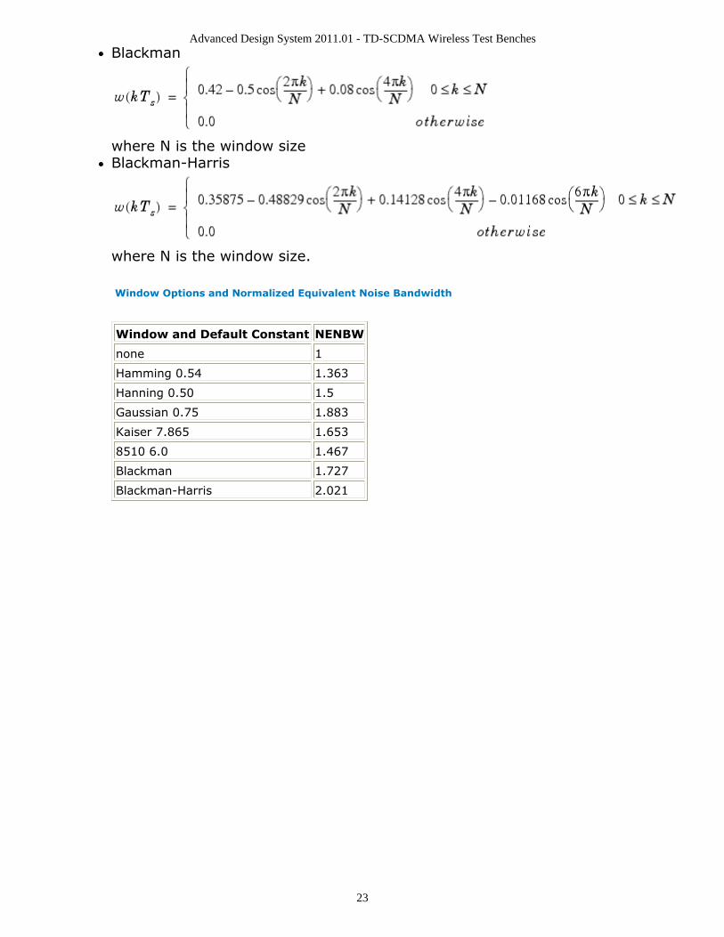
Blackman
where N is the window sizeBlackman-Harris
where N is the window size.
Window Options and Normalized Equivalent Noise Bandwidth
Window and Default Constant NENBW
none 1
Hamming 0.54 1.363
Hanning 0.50 1.5
Gaussian 0.75 1.883
Kaiser 7.865 1.653
8510 6.0 1.467
Blackman 1.727
Blackman-Harris 2.021
Advanced Design System 2011.01 - TD-SCDMA Wireless Test Benches
24
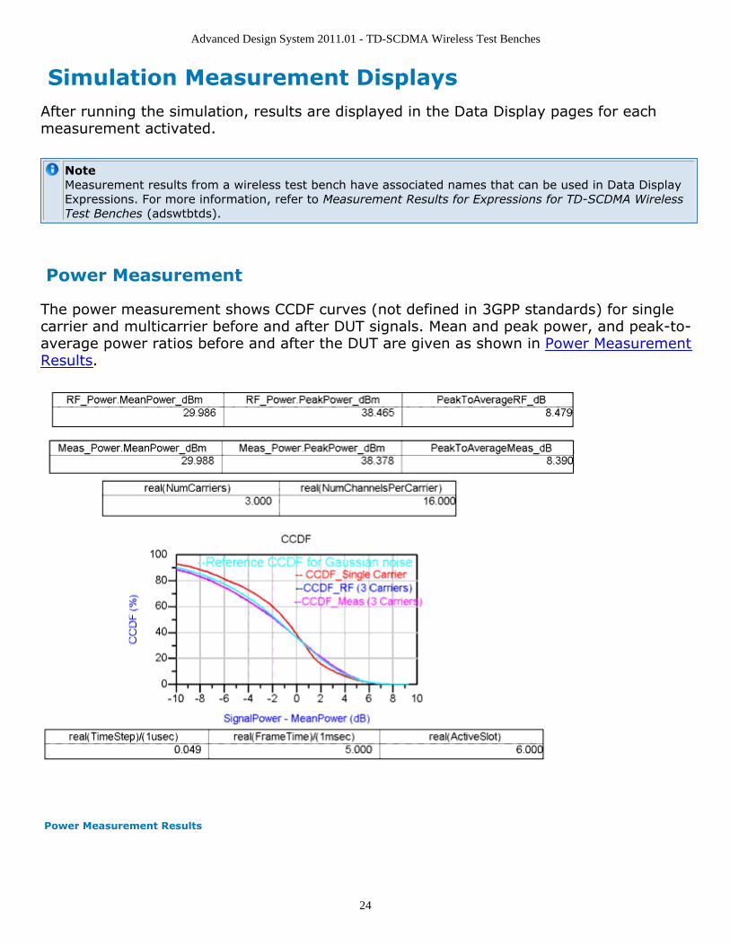
Simulation Measurement DisplaysAfter running the simulation, results are displayed in the Data Display pages for eachmeasurement activated.
NoteMeasurement results from a wireless test bench have associated names that can be used in Data DisplayExpressions. For more information, refer to Measurement Results for Expressions for TD-SCDMA WirelessTest Benches (adswtbtds).
Power Measurement
The power measurement shows CCDF curves (not defined in 3GPP standards) for singlecarrier and multicarrier before and after DUT signals. Mean and peak power, and peak-to-average power ratios before and after the DUT are given as shown in Power MeasurementResults.
Power Measurement Results
Advanced Design System 2011.01 - TD-SCDMA Wireless Test Benches
25
Spectrum Measurement
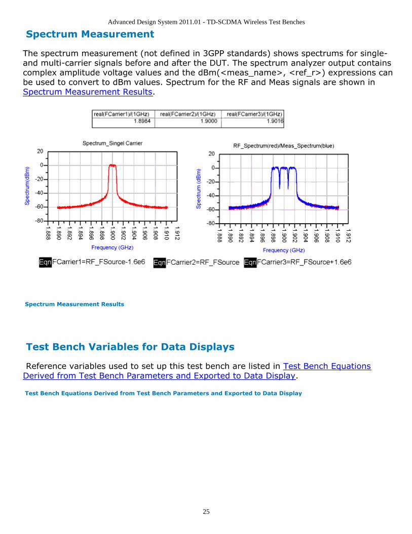
The spectrum measurement (not defined in 3GPP standards) shows spectrums for single-and multi-carrier signals before and after the DUT. The spectrum analyzer output containscomplex amplitude voltage values and the dBm(<meas_name>, <ref_r>) expressions canbe used to convert to dBm values. Spectrum for the RF and Meas signals are shown inSpectrum Measurement Results.
Spectrum Measurement Results
Test Bench Variables for Data Displays
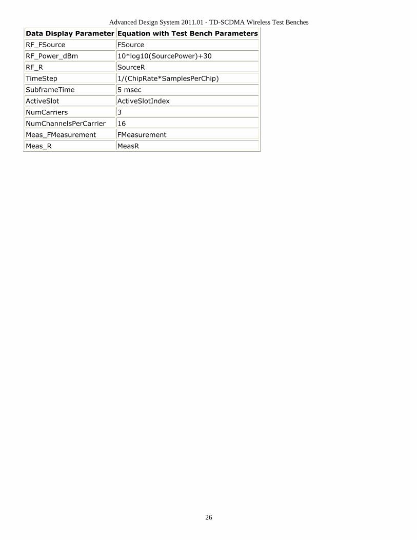
Reference variables used to set up this test bench are listed in Test Bench EquationsDerived from Test Bench Parameters and Exported to Data Display.
Test Bench Equations Derived from Test Bench Parameters and Exported to Data Display
Advanced Design System 2011.01 - TD-SCDMA Wireless Test Benches
26
Data Display Parameter Equation with Test Bench Parameters
RF_FSource FSource
RF_Power_dBm 10*log10(SourcePower)+30
RF_R SourceR
TimeStep 1/(ChipRate*SamplesPerChip)
SubframeTime 5 msec
ActiveSlot ActiveSlotIndex
NumCarriers 3
NumChannelsPerCarrier 16
Meas_FMeasurement FMeasurement
Meas_R MeasR
Advanced Design System 2011.01 - TD-SCDMA Wireless Test Benches
27
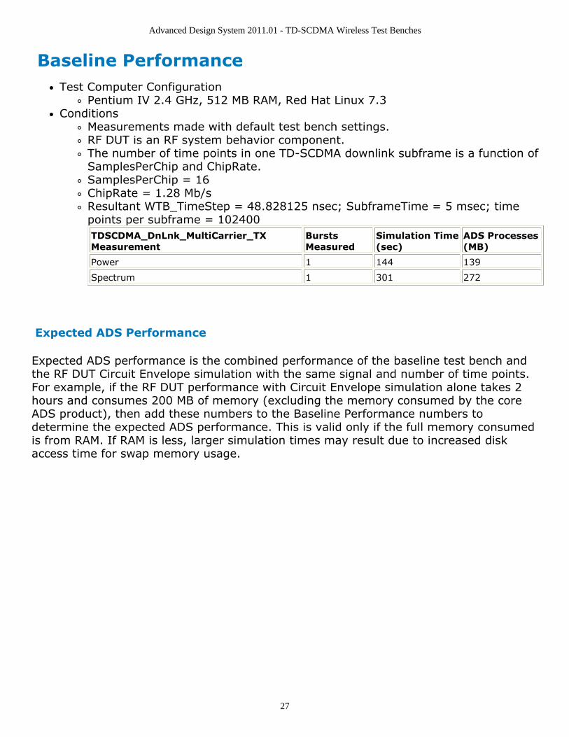
Baseline PerformanceTest Computer Configuration
Pentium IV 2.4 GHz, 512 MB RAM, Red Hat Linux 7.3Conditions
Measurements made with default test bench settings.RF DUT is an RF system behavior component.The number of time points in one TD-SCDMA downlink subframe is a function ofSamplesPerChip and ChipRate.SamplesPerChip = 16ChipRate = 1.28 Mb/sResultant WTB_TimeStep = 48.828125 nsec; SubframeTime = 5 msec; timepoints per subframe = 102400TDSCDMA_DnLnk_MultiCarrier_TXMeasurement
BurstsMeasured
Simulation Time(sec)
ADS Processes(MB)
Power 1 144 139
Spectrum 1 301 272
Expected ADS Performance
Expected ADS performance is the combined performance of the baseline test bench andthe RF DUT Circuit Envelope simulation with the same signal and number of time points.For example, if the RF DUT performance with Circuit Envelope simulation alone takes 2hours and consumes 200 MB of memory (excluding the memory consumed by the coreADS product), then add these numbers to the Baseline Performance numbers todetermine the expected ADS performance. This is valid only if the full memory consumedis from RAM. If RAM is less, larger simulation times may result due to increased diskaccess time for swap memory usage.
Advanced Design System 2011.01 - TD-SCDMA Wireless Test Benches
28
References3GPP TS 25.221, "3rd Generation Partnership Project; Technical Specification Group1.Radio Access Network; Physical channels and mapping of transport channels ontophysical channels (TDD) (Release 4)," version 4.5.0, June, 2002.http://www.3gpp.org/ftp/Specs/2002-06/Rel-4/25_series/25221-450.zip ]3GPP TS 25.223, "3rd Generation Partnership Project; Technical Specification Group2.Radio Access Network; Spreading and modulation (TDD) (Release 4)," version 4.4.0,March, 2002.http://www.3gpp.org/ftp/Specs/2002-06/Rel-4/25_series/25223-440.zip ]Setting up a Wireless Test Bench Analysis in the Wireless Test Bench Simulationdocumentation explains how to use test bench windows and dialogs to performanalysis tasks.Setting Circuit Envelope Analysis Parameters in the Wireless Test Bench Simulationdocumentation explains how to set up circuit envelope analysis parameters such asconvergence criteria, solver selection, and initial guess.Setting Automatic Verification Modeling Parameters in the Wireless Test BenchSimulation documentation explains how to improve simulation speed.
Advanced Design System 2011.01 - TD-SCDMA Wireless Test Benches
29
Downlink Receiver Adjacent ChannelSelectivity Test
Advanced Design System 2011.01 - TD-SCDMA Wireless Test Benches
30
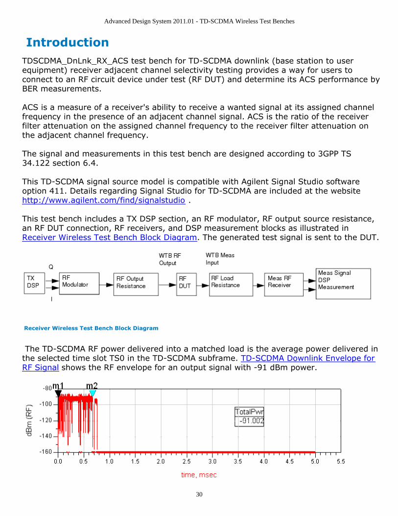
IntroductionTDSCDMA_DnLnk_RX_ACS test bench for TD-SCDMA downlink (base station to userequipment) receiver adjacent channel selectivity testing provides a way for users toconnect to an RF circuit device under test (RF DUT) and determine its ACS performance byBER measurements.
ACS is a measure of a receiver's ability to receive a wanted signal at its assigned channelfrequency in the presence of an adjacent channel signal. ACS is the ratio of the receiverfilter attenuation on the assigned channel frequency to the receiver filter attenuation onthe adjacent channel frequency.
The signal and measurements in this test bench are designed according to 3GPP TS34.122 section 6.4.
This TD-SCDMA signal source model is compatible with Agilent Signal Studio softwareoption 411. Details regarding Signal Studio for TD-SCDMA are included at the websitehttp://www.agilent.com/find/signalstudio .
This test bench includes a TX DSP section, an RF modulator, RF output source resistance,an RF DUT connection, RF receivers, and DSP measurement blocks as illustrated inReceiver Wireless Test Bench Block Diagram. The generated test signal is sent to the DUT.
Receiver Wireless Test Bench Block Diagram
The TD-SCDMA RF power delivered into a matched load is the average power delivered inthe selected time slot TS0 in the TD-SCDMA subframe. TD-SCDMA Downlink Envelope forRF Signal shows the RF envelope for an output signal with -91 dBm power.
Advanced Design System 2011.01 - TD-SCDMA Wireless Test Benches
31
TD-SCDMA Downlink Envelope for RF Signal
Advanced Design System 2011.01 - TD-SCDMA Wireless Test Benches
32
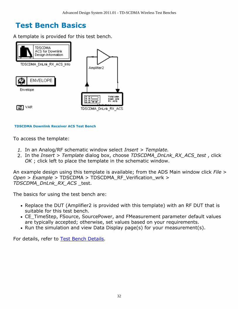
Test Bench BasicsA template is provided for this test bench.
TDSCDMA Downlink Receiver ACS Test Bench
To access the template:
In an Analog/RF schematic window select Insert > Template.1.In the Insert > Template dialog box, choose TDSCDMA_DnLnk_RX_ACS_test , click2.OK ; click left to place the template in the schematic window.
An example design using this template is available; from the ADS Main window click File >Open > Example > TDSCDMA > TDSCDMA_RF_Verification_wrk >TDSCDMA_DnLnk_RX_ACS _test.
The basics for using the test bench are:
Replace the DUT (Amplifier2 is provided with this template) with an RF DUT that issuitable for this test bench.CE_TimeStep, FSource, SourcePower, and FMeasurement parameter default valuesare typically accepted; otherwise, set values based on your requirements.Run the simulation and view Data Display page(s) for your measurement(s).
For details, refer to Test Bench Details.
Advanced Design System 2011.01 - TD-SCDMA Wireless Test Benches
33
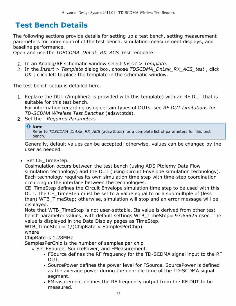
Test Bench DetailsThe following sections provide details for setting up a test bench, setting measurementparameters for more control of the test bench, simulation measurement displays, andbaseline performance.Open and use the TDSCDMA_DnLnk_RX_ACS_test template:
In an Analog/RF schematic window select Insert > Template.1.In the Insert > Template dialog box, choose TDSCDMA_DnLnk_RX_ACS_test , click2.OK ; click left to place the template in the schematic window.
The test bench setup is detailed here.
Replace the DUT (Amplifier2 is provided with this template) with an RF DUT that is1.suitable for this test bench.For information regarding using certain types of DUTs, see RF DUT Limitations forTD-SCDMA Wireless Test Benches (adswtbtds).Set the Required Parameters .2.
NoteRefer to TDSCDMA_DnLnk_RX_ACS (adswtbtds) for a complete list of parameters for this testbench.
Generally, default values can be accepted; otherwise, values can be changed by theuser as needed.
Set CE_TimeStep.Cosimulation occurs between the test bench (using ADS Ptolemy Data Flowsimulation technology) and the DUT (using Circuit Envelope simulation technology).Each technology requires its own simulation time step with time-step coordinationoccurring in the interface between the technologies.CE_TimeStep defines the Circuit Envelope simulation time step to be used with thisDUT. The CE_TimeStep must be set to a value equal to or a submultiple of (lessthan) WTB_TimeStep; otherwise, simulation will stop and an error message will bedisplayed.Note that WTB_TimeStep is not user-settable. Its value is derived from other testbench parameter values; with default settings WTB_TimeStep= 97.65625 nsec. Thevalue is displayed in the Data Display pages as TimeStep.WTB_TimeStep = 1/(ChipRate × SamplesPerChip)whereChipRate is 1.28MHzSamplesPerChip is the number of samples per chip
Set FSource, SourcePower, and FMeasurement.FSource defines the RF frequency for the TD-SCDMA signal input to the RFDUT.SourcePower defines the power level for FSource. SourcePower is definedas the average power during the non-idle time of the TD-SCDMA signalsegment.FMeasurement defines the RF frequency output from the RF DUT to bemeasured.
Advanced Design System 2011.01 - TD-SCDMA Wireless Test Benches
34
More control of the test bench can be achieved by setting parameters on the Basic1.Parameters , Signal Parameters , and the measurement categories. For details, referto Setting Parameters (adswtbtds).The RF modulator (shown in the block diagram in Receiver Wireless Test Bench Block2.Diagram) uses FSource, SourcePower ( Required Parameters ),MirrorSourceSpectrum ( Basic Parameters) , GainImbalance, PhaseImbalance,I_OriginOffset, Q_OriginOffset, and IQ_Rotation ( Signal Parameters ).The RF output resistance uses SourceR and SourceTemp ( Basic Parameters ). The RFoutput signal source has a 50-ohm (default) output resistance defined by SourceR.RF output (and input to the RF DUT) is at the frequency specified (FSource), with thespecified source resistance (SourceR) and with power (SourcePower) delivered into amatched load of resistance SourceR. The RF signal has additive Gaussian noise powerset by resistor temperature (SourceTemp).Note that the Meas_in point of the test bench provides a resistive load to the RF DUTset by the MeasR value (50-ohm default) ( Basic Parameters ).The Meas signal contains linear and nonlinear signal distortions and time delaysassociated with the RF DUT input to output characteristics.The DSP block (shown in the block diagram in Receiver Wireless Test Bench BlockDiagram) uses other Signal Parameters . More control of Circuit Envelope analysis can be achieved by setting Envelope3.controller parameters. These settings include Enable Fast Cosim, which may speedthe RF DUT simulation more than 10×. Setting these simulation options is describedin Setting Fast Cosimulation Parameters and Setting Circuit Envelope AnalysisParameters in the Wireless Test Bench Simulation documentation.After running a simulation, results will appear in a Data Display window for the4.measurement. Simulation Measurement Displays (adswtbtds) describes results foreach measurement. For general WTB Data Display details refer to Viewing WTBAnalysis Results (adswtbsim).
Advanced Design System 2011.01 - TD-SCDMA Wireless Test Benches
35
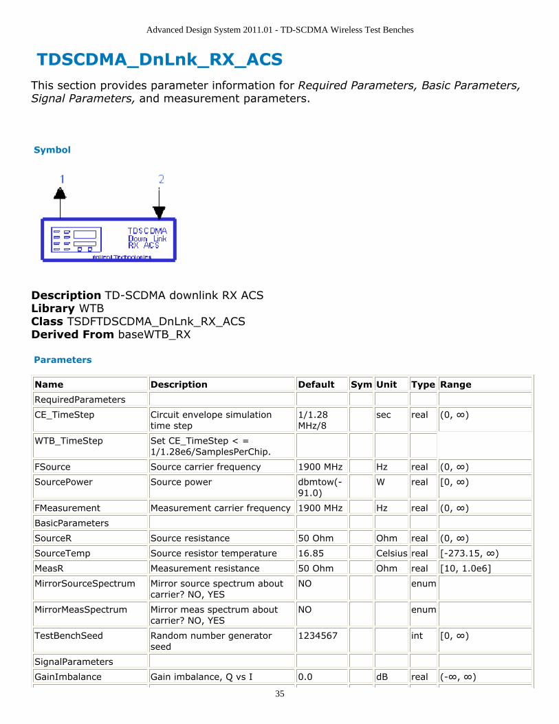
TDSCDMA_DnLnk_RX_ACS This section provides parameter information for Required Parameters, Basic Parameters,Signal Parameters, and measurement parameters.
Symbol
Description TD-SCDMA downlink RX ACSLibrary WTBClass TSDFTDSCDMA_DnLnk_RX_ACSDerived From baseWTB_RX
Parameters
Name Description Default Sym Unit Type Range
RequiredParameters
CE_TimeStep Circuit envelope simulationtime step
1/1.28MHz/8
sec real (0, ∞)
WTB_TimeStep Set CE_TimeStep < =1/1.28e6/SamplesPerChip.
FSource Source carrier frequency 1900 MHz Hz real (0, ∞)
SourcePower Source power dbmtow(-91.0)
W real [0, ∞)
FMeasurement Measurement carrier frequency 1900 MHz Hz real (0, ∞)
BasicParameters
SourceR Source resistance 50 Ohm Ohm real (0, ∞)
SourceTemp Source resistor temperature 16.85 Celsius real [-273.15, ∞)
MeasR Measurement resistance 50 Ohm Ohm real [10, 1.0e6]
MirrorSourceSpectrum Mirror source spectrum aboutcarrier? NO, YES
NO enum
MirrorMeasSpectrum Mirror meas spectrum aboutcarrier? NO, YES
NO enum
TestBenchSeed Random number generatorseed
1234567 int [0, ∞)
SignalParameters
GainImbalance Gain imbalance, Q vs I 0.0 dB real (-∞, ∞)
Advanced Design System 2011.01 - TD-SCDMA Wireless Test Benches
36
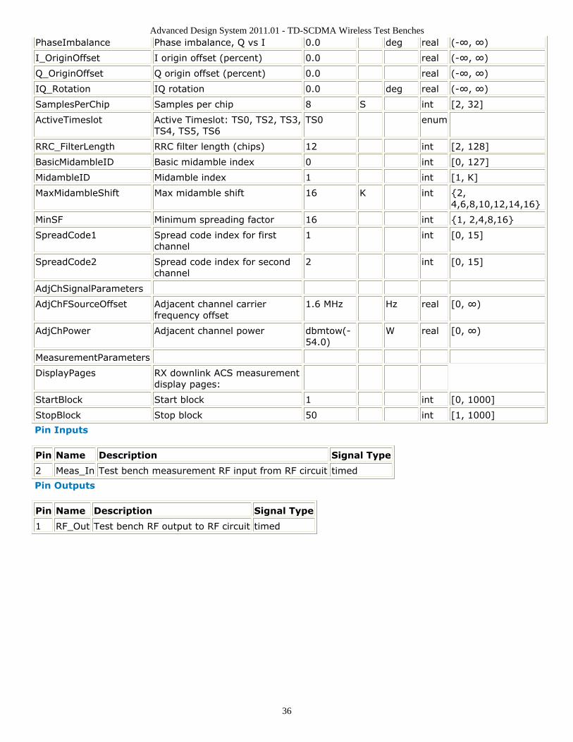
PhaseImbalance Phase imbalance, Q vs I 0.0 deg real (-∞, ∞)
I_OriginOffset I origin offset (percent) 0.0 real (-∞, ∞)
Q_OriginOffset Q origin offset (percent) 0.0 real (-∞, ∞)
IQ_Rotation IQ rotation 0.0 deg real (-∞, ∞)
SamplesPerChip Samples per chip 8 S int [2, 32]
ActiveTimeslot Active Timeslot: TS0, TS2, TS3,TS4, TS5, TS6
TS0 enum
RRC_FilterLength RRC filter length (chips) 12 int [2, 128]
BasicMidambleID Basic midamble index 0 int [0, 127]
MidambleID Midamble index 1 int [1, K]
MaxMidambleShift Max midamble shift 16 K int {2,4,6,8,10,12,14,16}
MinSF Minimum spreading factor 16 int {1, 2,4,8,16}
SpreadCode1 Spread code index for firstchannel
1 int [0, 15]
SpreadCode2 Spread code index for secondchannel
2 int [0, 15]
AdjChSignalParameters
AdjChFSourceOffset Adjacent channel carrierfrequency offset
1.6 MHz Hz real [0, ∞)
AdjChPower Adjacent channel power dbmtow(-54.0)
W real [0, ∞)
MeasurementParameters
DisplayPages RX downlink ACS measurementdisplay pages:
StartBlock Start block 1 int [0, 1000]
StopBlock Stop block 50 int [1, 1000]
Pin Inputs
Pin Name Description Signal Type
2 Meas_In Test bench measurement RF input from RF circuit timed
Pin Outputs
Pin Name Description Signal Type
1 RF_Out Test bench RF output to RF circuit timed
Advanced Design System 2011.01 - TD-SCDMA Wireless Test Benches
37
Setting ParametersMore control of the test bench can be achieved by setting parameters on the BasicParameters, Signal Parameters, Adjacent Channel Selectivity, and measurementcategories.
Basic Parameters
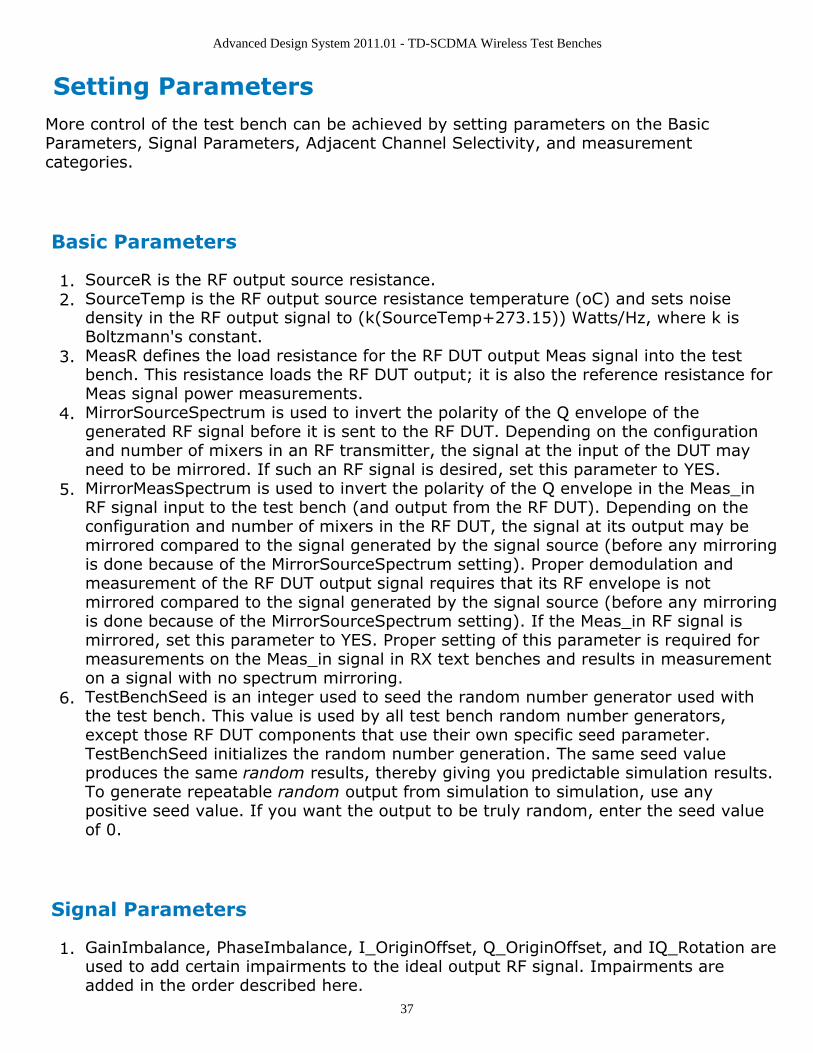
SourceR is the RF output source resistance.1.SourceTemp is the RF output source resistance temperature (oC) and sets noise2.density in the RF output signal to (k(SourceTemp+273.15)) Watts/Hz, where k isBoltzmann's constant.MeasR defines the load resistance for the RF DUT output Meas signal into the test3.bench. This resistance loads the RF DUT output; it is also the reference resistance forMeas signal power measurements.MirrorSourceSpectrum is used to invert the polarity of the Q envelope of the4.generated RF signal before it is sent to the RF DUT. Depending on the configurationand number of mixers in an RF transmitter, the signal at the input of the DUT mayneed to be mirrored. If such an RF signal is desired, set this parameter to YES.MirrorMeasSpectrum is used to invert the polarity of the Q envelope in the Meas_in5.RF signal input to the test bench (and output from the RF DUT). Depending on theconfiguration and number of mixers in the RF DUT, the signal at its output may bemirrored compared to the signal generated by the signal source (before any mirroringis done because of the MirrorSourceSpectrum setting). Proper demodulation andmeasurement of the RF DUT output signal requires that its RF envelope is notmirrored compared to the signal generated by the signal source (before any mirroringis done because of the MirrorSourceSpectrum setting). If the Meas_in RF signal ismirrored, set this parameter to YES. Proper setting of this parameter is required formeasurements on the Meas_in signal in RX text benches and results in measurementon a signal with no spectrum mirroring.TestBenchSeed is an integer used to seed the random number generator used with6.the test bench. This value is used by all test bench random number generators,except those RF DUT components that use their own specific seed parameter.TestBenchSeed initializes the random number generation. The same seed valueproduces the same random results, thereby giving you predictable simulation results.To generate repeatable random output from simulation to simulation, use anypositive seed value. If you want the output to be truly random, enter the seed valueof 0.
Signal Parameters
GainImbalance, PhaseImbalance, I_OriginOffset, Q_OriginOffset, and IQ_Rotation are1.used to add certain impairments to the ideal output RF signal. Impairments areadded in the order described here.
Advanced Design System 2011.01 - TD-SCDMA Wireless Test Benches
38
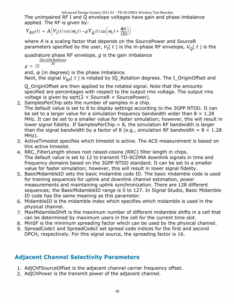
The unimpaired RF I and Q envelope voltages have gain and phase imbalanceapplied. The RF is given by:
where A is a scaling factor that depends on the SourcePower and SourceRparameters specified by the user, VI( t ) is the in-phase RF envelope, VQ( t ) is the
quadrature phase RF envelope, g is the gain imbalance
and, φ (in degrees) is the phase imbalance.Next, the signal VRF( t ) is rotated by IQ_Rotation degrees. The I_OriginOffset and
Q_OriginOffset are then applied to the rotated signal. Note that the amountsspecified are percentages with respect to the output rms voltage. The output rmsvoltage is given by sqrt(2 × SourceR × SourcePower).SamplesPerChip sets the number of samples in a chip.2.The default value is set to 8 to display settings according to the 3GPP NTDD. It canbe set to a larger value for a simulation frequency bandwidth wider than 8 × 1.28MHz. It can be set to a smaller value for faster simulation; however, this will result inlower signal fidelity. If SamplesPerChip = 8, the simulation RF bandwidth is largerthan the signal bandwidth by a factor of 8 (e.g., simulation RF bandwidth = 8 × 1.28MHz).ActiveTimeslot specifies which timeslot is active. The ACS measurement is based on3.this active timeslot.RRC_FilterLength shows root raised-cosine (RRC) filter length in chips.4.The default value is set to 12 to transmit TD-SCDMA downlink signals in time andfrequency domains based on the 3GPP NTDD standard. It can be set to a smallervalue for faster simulation; however, this will result in lower signal fidelity.BasicMidambleID sets the basic midamble code ID. The basic midamble code is used5.for training sequences for uplink and downlink channel estimation, powermeasurements and maintaining uplink synchronization. There are 128 differentsequences; the BasicMidambleID range is 0 to 127. In Signal Studio, Basic MidambleID code has the same meaning as this parameter.MidambleID is the midamble index which specifies which midamble is used in the6.physical channel.MaxMidambleShift is the maximum number of different midamble shifts in a cell that7.can be determined by maximum users in the cell for the current time slot.MinSF is the minimum spreading factor which can be used by the physical channel.8.SpreadCode1 and SpreadCode2 set spread code indices for the first and second9.DPCH, respectively. For this signal source, the spreading factor is 16.
Adjacent Channel Selectivity Parameters
AdjChFSourceOffset is the adjacent channel carrier frequency offset.1.AdjChPower is the transmit power of the adjacent channel.2.
Advanced Design System 2011.01 - TD-SCDMA Wireless Test Benches
39
Measurement Parameters
This measurement requires setting the MirrorMeasSpectrum parameter such that there isan even number of spectrum mirrorings from the combined test bench source and RFDUT. For example, if MirrorSourceSpectrum = NO and the RF DUT causes its output RFsignal to have spectrum mirroring relative to its input signal, then set MirrorMeasSpectrum= YES.
DisplayPages provides Data Display page information for this test bench. It cannot be1.changed by the user.StartBlock sets the start block. The block is the unit set of TD-SCDMA subframes for2.processing channel coding. One block contains four subframes. A value of 0 is thefirst block.StopBlock sets the stop block. For example, StopBlock=50 results in a measurement3.of 51 blocks.
Advanced Design System 2011.01 - TD-SCDMA Wireless Test Benches
40
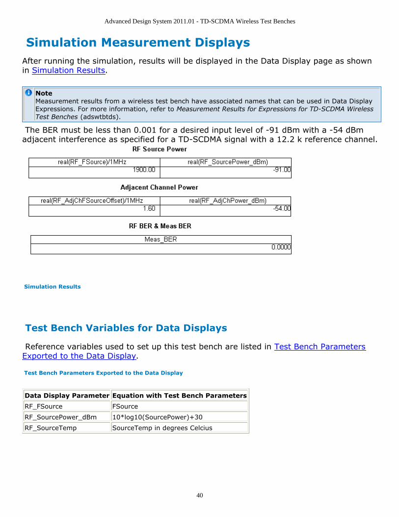
Simulation Measurement DisplaysAfter running the simulation, results will be displayed in the Data Display page as shownin Simulation Results.
NoteMeasurement results from a wireless test bench have associated names that can be used in Data DisplayExpressions. For more information, refer to Measurement Results for Expressions for TD-SCDMA WirelessTest Benches (adswtbtds).
The BER must be less than 0.001 for a desired input level of -91 dBm with a -54 dBmadjacent interference as specified for a TD-SCDMA signal with a 12.2 k reference channel.
Simulation Results
Test Bench Variables for Data Displays
Reference variables used to set up this test bench are listed in Test Bench ParametersExported to the Data Display.
Test Bench Parameters Exported to the Data Display
Data Display Parameter Equation with Test Bench Parameters
RF_FSource FSource
RF_SourcePower_dBm 10*log10(SourcePower)+30
RF_SourceTemp SourceTemp in degrees Celcius

Advanced Design System 2011.01 - TD-SCDMA Wireless Test Benches
41
Baseline PerformanceTest Computer Configuration
Pentium IV 2.4 GHz, 512 MB RAM, Red Hat Linux 7.3Conditions
Measurements made with default test bench settings.RF DUT is an RF system behavior component.The number of time points in one TD-SCDMA downlink subframe is a function ofSamplesPerChip and ChipRate.SamplesPerChip = 8ChipRate = 1.28 Mb/sResultant WTB_TimeStep = 97.65625 nsec; SubframeTime = 5 msec; timepoints per subframe = 51200
Simulation time and memory requirements:TDSCDMA_DnLnk_RXMeasurement*
BurstsMeasured
Simulation Time(sec)
ADS Processes(MB)
ACS 50 513 112
Expected ADS Performance
Expected ADS performance is the combined performance of the baseline test bench andthe RF DUT Circuit Envelope simulation with the same signal and number of time points.For example, if the RF DUT performance with Circuit Envelope simulation alone takes 2hours and consumes 200 MB of memory (excluding the memory consumed by the coreADS product), then add these numbers to the Baseline Performance numbers todetermine the expected ADS performance. This is valid only if the full memory consumedis from RAM. If RAM is less, larger simulation times may result due to increased diskaccess time for swap memory usage.
Advanced Design System 2011.01 - TD-SCDMA Wireless Test Benches
42
References3GPP TS 25.221, "3rd Generation Partnership Project; Technical Specification Group1.Radio Access Network; Physical channels and mapping of transport channels ontophysical channels (TDD) (Release 4)," version 4.5.0, June, 2002.http://www.3gpp.org/ftp/Specs/2002-06/Rel-4/25_series/25221-450.zip ]3GPP TS 25.223, "3rd Generation Partnership Project; Technical Specification Group2.Radio Access Network; Spreading and modulation (TDD) (Release 4)," version 4.4.0,March, 2002.http://www.3gpp.org/ftp/Specs/2002-06/Rel-4/25_series/25223-440.zip ]3GPP TS 25.102, "3rd Generation Partnership Project; Technical Specification Group3.Radio Access Networks; UE Radio Transmission and Reception (TDD) (Release 4),"version 4.5.0, June, 2002.http://www.3gpp.org/ftp/Specs/2002-06/Rel-4/25_series/25102-450.zip ]3GPP TS 34.122, "3rd Generation Partnership Project; Technical Specification Group4.Terminal; Terminal Conformance Specification; Radio Transmission and Reception(TDD) (Release 4)," version 4.4.0, June, 2002.http://www.3gpp.org/ftp/Specs/2002-06/Rel-4/34_series/34122-440.zip ]Setting up a Wireless Test Bench Analysis in the Wireless Test Bench Simulationdocumentation explains how to use test bench windows and dialogs to performanalysis tasks.Setting Circuit Envelope Analysis Parameters in the Wireless Test Bench Simulationdocumentation explains how to set up circuit envelope analysis parameters such asconvergence criteria, solver selection, and initial guess.Setting Automatic Verification Modeling Parameters in the Wireless Test BenchSimulation documentation explains how to improve simulation speed.
Advanced Design System 2011.01 - TD-SCDMA Wireless Test Benches
43
Downlink Transmitter Test
Advanced Design System 2011.01 - TD-SCDMA Wireless Test Benches
44
IntroductionTDSCDMA_DnLnk_TX text bench for TDSCDMA downlink (base station to user equipment)transmitter testing provides a way for users to connect to an RF circuit device under test(RF DUT) and determine its performance by activating various measurements. This testbench provides signal measurements for RF envelope, constellation, power (includingpower vs. time and CCDF), spectrum, and EVM.
The signal and most of the measurements are designed according to 3GPP TS 25 (Release4).
This TD-SCDMA signal source model is compatible with Agilent Signal Studio softwareoption 411. Details regarding Signal Studio for TD-SCDMA are included at the websitehttp://www.agilent.com/find/signalstudio .
The DUT output signal can be sent to an Agilent ESG RF signal generator.
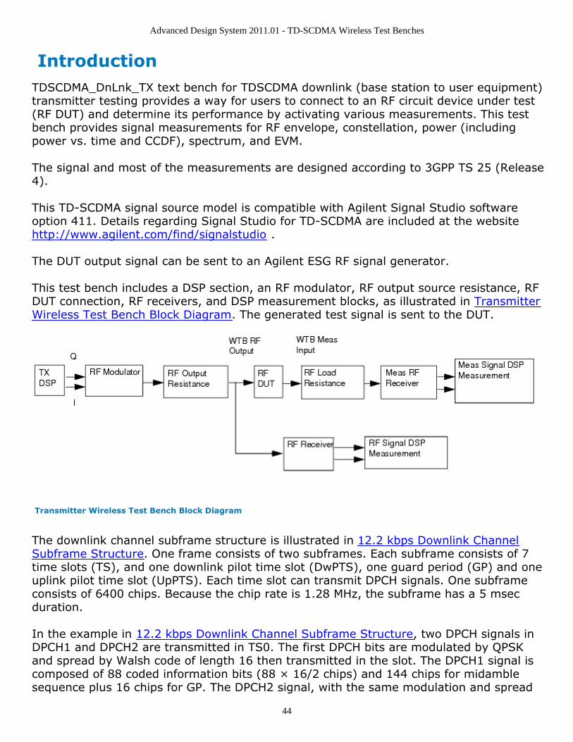
This test bench includes a DSP section, an RF modulator, RF output source resistance, RFDUT connection, RF receivers, and DSP measurement blocks, as illustrated in TransmitterWireless Test Bench Block Diagram. The generated test signal is sent to the DUT.
Transmitter Wireless Test Bench Block Diagram
The downlink channel subframe structure is illustrated in 12.2 kbps Downlink ChannelSubframe Structure. One frame consists of two subframes. Each subframe consists of 7time slots (TS), and one downlink pilot time slot (DwPTS), one guard period (GP) and oneuplink pilot time slot (UpPTS). Each time slot can transmit DPCH signals. One subframeconsists of 6400 chips. Because the chip rate is 1.28 MHz, the subframe has a 5 msecduration.
In the example in 12.2 kbps Downlink Channel Subframe Structure, two DPCH signals inDPCH1 and DPCH2 are transmitted in TS0. The first DPCH bits are modulated by QPSKand spread by Walsh code of length 16 then transmitted in the slot. The DPCH1 signal iscomposed of 88 coded information bits (88 × 16/2 chips) and 144 chips for midamblesequence plus 16 chips for GP. The DPCH2 signal, with the same modulation and spread
Advanced Design System 2011.01 - TD-SCDMA Wireless Test Benches
45
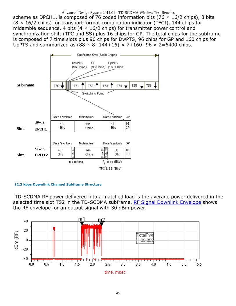
scheme as DPCH1, is composed of 76 coded information bits (76 × 16/2 chips), 8 bits(8 × 16/2 chips) for transport format combination indicator (TFCI), 144 chips formidamble sequence, 4 bits (4 × 16/2 chips) for transmitter power control andsynchronization shift (TPC and SS) plus 16 chips for GP. The total chips for the subframeis composed of 7 time slots plus 96 chips for DwPTS, 96 chips for GP and 160 chips forUpPTS and summarized as (88 × 8+144+16) × 7+160+96 × 2=6400 chips.
12.2 kbps Downlink Channel Subframe Structure
TD-SCDMA RF power delivered into a matched load is the average power delivered in theselected time slot TS2 in the TD-SCDMA subframe. RF Signal Downlink Envelope showsthe RF envelope for an output signal with 30 dBm power.

Advanced Design System 2011.01 - TD-SCDMA Wireless Test Benches
46
RF Signal Downlink Envelope
Advanced Design System 2011.01 - TD-SCDMA Wireless Test Benches
47
Test Bench BasicsA template is provided for this test bench.
TDSCDMA Downlink Transmitter Test Bench
To access the template:
In an Analog/RF schematic window select Insert > Template.1.In the Insert > Template dialog box, choose TDSCDMA_DnLnk_TX_test , click OK ;2.click left to place the template in the schematic window.
An example design using this template is available; from the ADS Main window click File >Open > Example > TDSCDMA > TDSCDMA_RF_Verification_wrk >TDSCDMA_DnLnk_TX_test.
The basics for using the test bench are:
Replace the DUT (Amplifier2 is provided with this template) with an RF DUT that issuitable for this test bench.CE_TimeStep, FSource, SourcePower, and FMeasurement parameter default valuesare typically accepted; otherwise, set values based on your requirements.Activate/deactivate measurements based on your requirements.Run the simulation and view Data Display page(s) for your measurement(s).
For details, refer to Test Bench Details.
Advanced Design System 2011.01 - TD-SCDMA Wireless Test Benches
48
Test Bench DetailsThe following sections provide details for setting up a test bench, setting measurementparameters for more control of the test bench, simulation measurement displays, andbaseline performance.Open and use the TDSCDMA_DnLnk_TX template:
In an Analog/RF schematic window select Insert > Template.1.In the Insert > Template dialog box, choose TDSCDMA_DnLnk_TX_test , click OK ;2.click left to place the template in the schematic window.
Test bench setup is detailed here.
Replace the DUT (Amplifier2 is provided with this template) with an RF DUT that is1.suitable for this test bench.For information regarding using certain types of DUTs, see RF DUT Limitations forTD-SCDMA Wireless Test Benches (adswtbtds).Set the Required Parameters2.
NoteRefer to TDSCDMA_DnLnk_TX (adswtbtds) for a complete list of parameters for this test bench.
Generally, default values can be accepted; otherwise, values can be changed by theuser as needed.
Set CE_TimeStep.Cosimulation occurs between the test bench (using ADS Ptolemy Data Flowsimulation technology) and the DUT (using Circuit Envelope simulationtechnology). Each technology requires its own simulation time step with time-step coordination occurring in the interface between the technologies.CE_TimeStep defines the Circuit Envelope simulation time step to be used withthis DUT. The CE_TimeStep must be set to a value equal to or a submultiple of(less than) WTB_TimeStep; otherwise, simulation will stop and an errormessage will be displayed.Note that WTB_TimeStep is not user-settable. Its value is derived from othertest bench parameter values; with default settings WTB_TimeStep= 97.65625nsec. The value is displayed in the Data Display pages as TimeStep.WTB_TimeStep = 1/(ChipRate × SamplesPerChip)whereChipRate is 1.28MHzSamplesPerChip is the number of samples per chipSet FSource, SourcePower, and FMeasurement.
FSource defines the RF frequency for the TD-SCDMA signal input to the RFDUT.SourcePower defines the power level for FSource. SourcePower is definedas the average power during the non-idle time of the TD-SCDMA signalsegment.FMeasurement defines the RF frequency output from the RF DUT to bemeasured.
Activate/deactivate ( YES / NO ) test bench measurements (refer to3.
Advanced Design System 2011.01 - TD-SCDMA Wireless Test Benches
49
TDSCDMA_DnLnk_TX (adswtbtds)). At least one measurement must be enabled:RF_EnvelopeMeasurementConstellationPowerMeasurementSpectrumMeasurementEVM_Measurement
More control of the test bench can be achieved by setting parameters in the Basic4.Parameters , Signal Parameters , and measurement categories for each activatedmeasurement. For details, refer to Setting Parameters (adswtbtds). The RFmodulator (shown in the block diagram in Transmitter Wireless Test Bench BlockDiagram) uses FSource, SourcePower ( Required Parameters ),MirrorSourceSpectrum ( Basic Parameters) , GainImbalance, PhaseImbalance,I_OriginOffset, Q_OriginOffset, and IQ_Rotation ( Signal Parameters ).The RF output resistance uses SourceR, SourceTemp, and EnableSourceNoise ( BasicParameters ). The RF output signal source has a 50-ohm (default) output resistancedefined by SourceR.RF output (and input to the RF DUT) is at the frequency specified (FSource), with thespecified source resistance (SourceR) and with power (SourcePower) delivered into amatched load of resistance SourceR. The RF signal has additive Gaussian noise powerset by resistor temperature (SourceTemp) (when EnableSourceNoise=YES).Note that the Meas_in point of the test bench provides a resistive load to the RF DUTset by the MeasR value (50-ohm default) ( Basic Parameters ).The Meas signal contains linear and nonlinear signal distortions and time delaysassociated with the RF DUT input to output characteristics.The TX DSP block (shown in the block diagram in Transmitter Wireless Test BenchBlock Diagram) uses other Signal Parameters . More control of Circuit Envelope analysis can be achieved by setting Envelope5.controller parameters. These settings include Enable Fast Cosim, which may speedthe RF DUT simulation more than 10×. Setting these simulation options is describedin Setting Fast Cosimulation Parameters and Setting Circuit Envelope AnalysisParameters in the Wireless Test Bench Simulation documentation. To send the RF DUT output signal to an Agilent ESG RF signal generator, set6.parameters on the Signal to ESG category.For details, refer to Signal to ESG Parameters (adswtbtds).After running a simulation, results will appear in a Data Display window for the7.measurement. Simulation Measurement Displays (adswtbtds) describes results foreach measurement. For general WTB Data Display details refer to Viewing WTBAnalysis Results (adswtbsim).
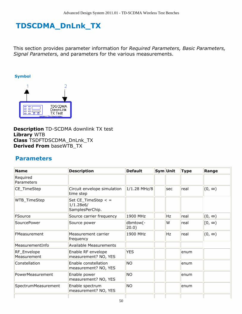
Advanced Design System 2011.01 - TD-SCDMA Wireless Test Benches
50
TDSCDMA_DnLnk_TX
This section provides parameter information for Required Parameters, Basic Parameters,Signal Parameters, and parameters for the various measurements.
Symbol
Description TD-SCDMA downlink TX testLibrary WTBClass TSDFTDSCDMA_DnLnk_TXDerived From baseWTB_TX
Parameters
Name Description Default Sym Unit Type Range
RequiredParameters
CE_TimeStep Circuit envelope simulationtime step
1/1.28 MHz/8 sec real (0, ∞)
WTB_TimeStep Set CE_TimeStep < =1/1.28e6/SamplesPerChip.
FSource Source carrier frequency 1900 MHz Hz real (0, ∞)
SourcePower Source power dbmtow(-20.0)
W real [0, ∞)
FMeasurement Measurement carrierfrequency
1900 MHz Hz real (0, ∞)
MeasurementInfo Available Measurements
RF_EnvelopeMeasurement
Enable RF envelopemeasurement? NO, YES
YES enum
Constellation Enable constellationmeasurement? NO, YES
NO enum
PowerMeasurement Enable powermeasurement? NO, YES
NO enum
SpectrumMeasurement Enable spectrummeasurement? NO, YES
NO enum
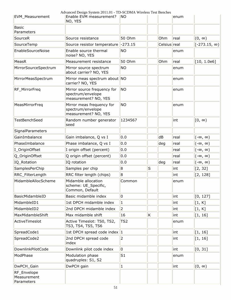
Advanced Design System 2011.01 - TD-SCDMA Wireless Test Benches
51
EVM_Measurement Enable EVM measurement?NO, YES
NO enum
BasicParameters
SourceR Source resistance 50 Ohm Ohm real (0, ∞)
SourceTemp Source resistor temperature -273.15 Celsius real [-273.15, ∞)
EnableSourceNoise Enable source thermalnoise? NO, YES
NO enum
MeasR Measurement resistance 50 Ohm Ohm real [10, 1.0e6]
MirrorSourceSpectrum Mirror source spectrumabout carrier? NO, YES
NO enum
MirrorMeasSpectrum Mirror meas spectrum aboutcarrier? NO, YES
NO enum
RF_MirrorFreq Mirror source frequency forspectrum/envelopemeasurement? NO, YES
NO enum
MeasMirrorFreq Mirror meas frequency forspectrum/envelopemeasurement? NO, YES
NO enum
TestBenchSeed Random number generatorseed
1234567 int [0, ∞)
SignalParameters
GainImbalance Gain imbalance, Q vs I 0.0 dB real (-∞, ∞)
PhaseImbalance Phase imbalance, Q vs I 0.0 deg real (-∞, ∞)
I_OriginOffset I origin offset (percent) 0.0 real (-∞, ∞)
Q_OriginOffset Q origin offset (percent) 0.0 real (-∞, ∞)
IQ_Rotation IQ rotation 0.0 deg real (-∞, ∞)
SamplesPerChip Samples per chip 8 S int [2, 32]
RRC_FilterLength RRC filter length (chips) 8 int [2, 128]
MidambleAllocScheme Midamble allocationscheme: UE_Specific,Common, Default
Common enum
BasicMidambleID Basic midamble index 0 int [0, 127]
MidambleID1 1st DPCH midamble index 1 int [1, K]
MidambleID2 2nd DPCH midamble index 2 int [1, K]
MaxMidambleShift Max midamble shift 16 K int [1, 16]
ActiveTimeslot Active Timeslot: TS0, TS2,TS3, TS4, TS5, TS6
TS2 enum
SpreadCode1 1st DPCH spread code index 1 int [1, 16]
SpreadCode2 2nd DPCH spread codeindex
2 int [1, 16]
DownlinkPilotCode Downlink pilot code index 0 int [0, 31]
ModPhase Modulation phasequadruples: S1, S2
S1 enum
DwPCH_Gain DwPCH gain 1 int (0, ∞)
RF_EnvelopeMeasurementParameters
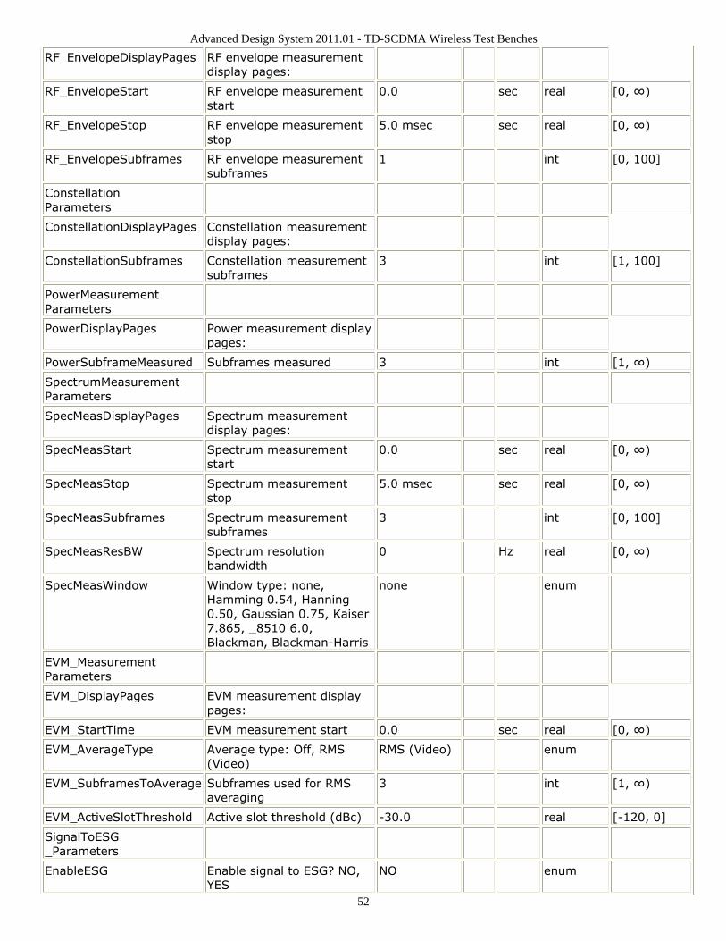
Advanced Design System 2011.01 - TD-SCDMA Wireless Test Benches
52
RF_EnvelopeDisplayPages RF envelope measurementdisplay pages:
RF_EnvelopeStart RF envelope measurementstart
0.0 sec real [0, ∞)
RF_EnvelopeStop RF envelope measurementstop
5.0 msec sec real [0, ∞)
RF_EnvelopeSubframes RF envelope measurementsubframes
1 int [0, 100]
ConstellationParameters
ConstellationDisplayPages Constellation measurementdisplay pages:
ConstellationSubframes Constellation measurementsubframes
3 int [1, 100]
PowerMeasurementParameters
PowerDisplayPages Power measurement displaypages:
PowerSubframeMeasured Subframes measured 3 int [1, ∞)
SpectrumMeasurementParameters
SpecMeasDisplayPages Spectrum measurementdisplay pages:
SpecMeasStart Spectrum measurementstart
0.0 sec real [0, ∞)
SpecMeasStop Spectrum measurementstop
5.0 msec sec real [0, ∞)
SpecMeasSubframes Spectrum measurementsubframes
3 int [0, 100]
SpecMeasResBW Spectrum resolutionbandwidth
0 Hz real [0, ∞)
SpecMeasWindow Window type: none,Hamming 0.54, Hanning0.50, Gaussian 0.75, Kaiser7.865, _8510 6.0,Blackman, Blackman-Harris
none enum
EVM_MeasurementParameters
EVM_DisplayPages EVM measurement displaypages:
EVM_StartTime EVM measurement start 0.0 sec real [0, ∞)
EVM_AverageType Average type: Off, RMS(Video)
RMS (Video) enum
EVM_SubframesToAverage Subframes used for RMSaveraging
3 int [1, ∞)
EVM_ActiveSlotThreshold Active slot threshold (dBc) -30.0 real [-120, 0]
SignalToESG_Parameters
EnableESG Enable signal to ESG? NO,YES
NO enum
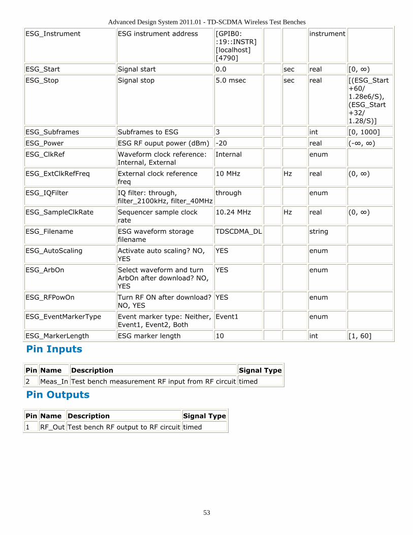
Advanced Design System 2011.01 - TD-SCDMA Wireless Test Benches
53
ESG_Instrument ESG instrument address [GPIB0::19::INSTR][localhost][4790]
instrument
ESG_Start Signal start 0.0 sec real [0, ∞)
ESG_Stop Signal stop 5.0 msec sec real [(ESG_Start+60/1.28e6/S),(ESG_Start+32/1.28/S)]
ESG_Subframes Subframes to ESG 3 int [0, 1000]
ESG_Power ESG RF ouput power (dBm) -20 real (-∞, ∞)
ESG_ClkRef Waveform clock reference:Internal, External
Internal enum
ESG_ExtClkRefFreq External clock referencefreq
10 MHz Hz real (0, ∞)
ESG_IQFilter IQ filter: through,filter_2100kHz, filter_40MHz
through enum
ESG_SampleClkRate Sequencer sample clockrate
10.24 MHz Hz real (0, ∞)
ESG_Filename ESG waveform storagefilename
TDSCDMA_DL string
ESG_AutoScaling Activate auto scaling? NO,YES
YES enum
ESG_ArbOn Select waveform and turnArbOn after download? NO,YES
YES enum
ESG_RFPowOn Turn RF ON after download?NO, YES
YES enum
ESG_EventMarkerType Event marker type: Neither,Event1, Event2, Both
Event1 enum
ESG_MarkerLength ESG marker length 10 int [1, 60]
Pin Inputs
Pin Name Description Signal Type
2 Meas_In Test bench measurement RF input from RF circuit timed
Pin Outputs
Pin Name Description Signal Type
1 RF_Out Test bench RF output to RF circuit timed
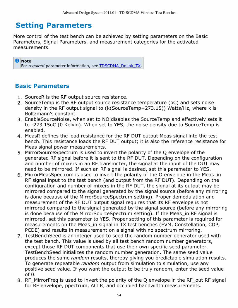
Advanced Design System 2011.01 - TD-SCDMA Wireless Test Benches
54
Setting ParametersMore control of the test bench can be achieved by setting parameters on the BasicParameters, Signal Parameters, and measurement categories for the activatedmeasurements.
NoteFor required parameter information, see TDSCDMA_DnLnk_TX.
Basic Parameters
SourceR is the RF output source resistance.1.SourceTemp is the RF output source resistance temperature (oC) and sets noise2.density in the RF output signal to (k(SourceTemp+273.15)) Watts/Hz, where k isBoltzmann's constant.EnableSourceNoise, when set to NO disables the SourceTemp and effectively sets it3.to -273.15oC (0 Kelvin). When set to YES, the noise density due to SourceTemp isenabled.MeasR defines the load resistance for the RF DUT output Meas signal into the test4.bench. This resistance loads the RF DUT output; it is also the reference resistance forMeas signal power measurements.MirrorSourceSpectrum is used to invert the polarity of the Q envelope of the5.generated RF signal before it is sent to the RF DUT. Depending on the configurationand number of mixers in an RF transmitter, the signal at the input of the DUT mayneed to be mirrored. If such an RF signal is desired, set this parameter to YES.MirrorMeasSpectrum is used to invert the polarity of the Q envelope in the Meas_in6.RF signal input to the test bench (and output from the RF DUT). Depending on theconfiguration and number of mixers in the RF DUT, the signal at its output may bemirrored compared to the signal generated by the signal source (before any mirroringis done because of the MirrorSourceSpectrum setting). Proper demodulation andmeasurement of the RF DUT output signal requires that its RF envelope is notmirrored compared to the signal generated by the signal source (before any mirroringis done because of the MirrorSourceSpectrum setting). If the Meas_in RF signal ismirrored, set this parameter to YES. Proper setting of this parameter is required formeasurements on the Meas_in signal in TX test benches (EVM, Constellation, CDP,PCDE) and results in measurement on a signal with no spectrum mirroring.TestBenchSeed is an integer used to seed the random number generator used with7.the test bench. This value is used by all test bench random number generators,except those RF DUT components that use their own specific seed parameter.TestBenchSeed initializes the random number generation. The same seed valueproduces the same random results, thereby giving you predictable simulation results.To generate repeatable random output from simulation to simulation, use anypositive seed value. If you want the output to be truly random, enter the seed valueof 0.RF_MirrorFreq is used to invert the polarity of the Q envelope in the RF_out RF signal8.for RF envelope, ppectrum, ACLR, and occupied bandwidth measurements.
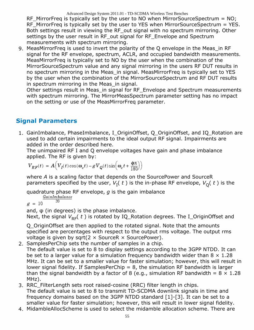
Advanced Design System 2011.01 - TD-SCDMA Wireless Test Benches
55
RF_MirrorFreq is typically set by the user to NO when MirrorSourceSpectrum = NO;RF_MirrorFreq is typically set by the user to YES when MirrorSourceSpectrum = YES.Both settings result in viewing the RF_out signal with no spectrum mirroring. Othersettings by the user result in RF_out signal for RF_Envelope and Spectrummeasurements with spectrum mirroring.MeasMirrorFreq is used to invert the polarity of the Q envelope in the Meas_in RF9.signal for the RF envelope, spectrum, ACLR, and occupied bandwidth measurements.MeasMirrorFreq is typically set to NO by the user when the combination of theMirrorSourceSpectrum value and any signal mirroring in the users RF DUT results inno spectrum mirroring in the Meas_in signal. MeasMirrorFreq is typically set to YESby the user when the combination of the MirrorSourceSpectrum and RF DUT resultsin spectrum mirroring in the Meas_in signal.Other settings result in Meas_in signal for RF_Envelope and Spectrum measurementswith spectrum mirroring. The MirrorMeasSpectrum parameter setting has no impacton the setting or use of the MeasMirrorFreq parameter.
Signal Parameters
GainImbalance, PhaseImbalance, I_OriginOffset, Q_OriginOffset, and IQ_Rotation are1.used to add certain impairments to the ideal output RF signal. Impairments areadded in the order described here.The unimpaired RF I and Q envelope voltages have gain and phase imbalanceapplied. The RF is given by:
where A is a scaling factor that depends on the SourcePower and SourceRparameters specified by the user, VI( t ) is the in-phase RF envelope, VQ( t ) is the
quadrature phase RF envelope, g is the gain imbalance
and, φ (in degrees) is the phase imbalance.Next, the signal VRF( t ) is rotated by IQ_Rotation degrees. The I_OriginOffset and
Q_OriginOffset are then applied to the rotated signal. Note that the amountsspecified are percentages with respect to the output rms voltage. The output rmsvoltage is given by sqrt(2 × SourceR × SourcePower).SamplesPerChip sets the number of samples in a chip.2.The default value is set to 8 to display settings according to the 3GPP NTDD. It canbe set to a larger value for a simulation frequency bandwidth wider than 8 × 1.28MHz. It can be set to a smaller value for faster simulation; however, this will result inlower signal fidelity. If SamplesPerChip = 8, the simulation RF bandwidth is largerthan the signal bandwidth by a factor of 8 (e.g., simulation RF bandwidth = 8 × 1.28MHz).RRC_FilterLength sets root raised-cosine (RRC) filter length in chips.3.The default value is set to 8 to transmit TD-SCDMA downlink signals in time andfrequency domains based on the 3GPP NTDD standard [1]-[3]. It can be set to asmaller value for faster simulation; however, this will result in lower signal fidelity.MidambleAllocScheme is used to select the midamble allocation scheme. There are4.
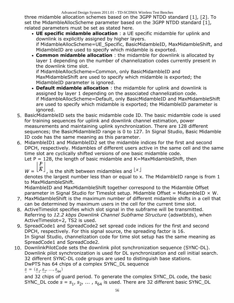
Advanced Design System 2011.01 - TD-SCDMA Wireless Test Benches
56
three midamble allocation schemes based on the 3GPP NTDD standard [1], [2]. Toset the MidambleAllocScheme parameter based on the 3GPP NTDD standard [1],related parameters must be set as stated here.
UE specific midamble allocation : a UE specific midamble for uplink anddownlink is explicitly assigned by higher layers.if MidambleAllocScheme=UE_Specific, BasicMidambleID, MaxMidambleShift, andMidambleID are used to specify which midamble is exported.Common midamble allocation : the midamble for downlink is allocated bylayer 1 depending on the number of channelization codes currently present inthe downlink time slot.if MidambleAllocScheme=Common, only BasicMidambleID andMaxMidambleShift are used to specify which midamble is exported; theMidambleID parameter is ignored.Default midamble allocation : the midamble for uplink and downlink isassigned by layer 1 depending on the associated channelization code.if MidambleAllocScheme=Default, only BasicMidambleID and MaxMidambleShiftare used to specify which midamble is exported; the MidambleID parameter isignored.
BasicMidambleID sets the basic midamble code ID. The basic midamble code is used5.for training sequences for uplink and downlink channel estimation, powermeasurements and maintaining uplink synchronization. There are 128 differentsequences; the BasicMidambleID range is 0 to 127. In Signal Studio, Basic MidambleID code has the same meaning as this parameter.MidambleID1 and MidambleID2 set the midamble indices for the first and second6.DPCH, respectively. Midambles of different users active in the same cell and the sametime slot are cyclically shifted versions of one basic midamble code.Let P = 128, the length of basic midamble and K=MaxMidambleShift, then
W = , is the shift between midambles and denotes the largest number less than or equal to x. The MidambleID range is from 1to MaxMidambleShift.MidambleID and MaxMidambleShift together correspond to the Midamble Offsetparameter in Signal Studio for Timeslot setup. Midamble Offset = MidambleID × W.MaxMidambleShift is the maximum number of different midamble shifts in a cell that7.can be determined by maximum users in the cell for the current time slot.ActiveTimeslot specifies which slot signal in the subframe will be transmitted.8.Referring to 12.2 kbps Downlink Channel Subframe Structure (adswtbtds), whenActiveTimeslot=2, TS2 is used.SpreadCode1 and SpreadCode2 set spread code indices for the first and second9.DPCH, respectively. For this signal source, the spreading factor is 16.In Signal Studio, channelization code for time slot setup has the same meaning asSpreadCode1 and SpreadCode2.DownlinkPilotCode sets the downlink pilot synchronization sequence (SYNC-DL).10.Downlink pilot synchronization is used for DL synchronization and cell initial search.32 different SYNC-DL code groups are used to distinguish base stations.DwPTS has 64 chips of a complex SYNC_DL sequence
and 32 chips of guard period. To generate the complex SYNC_DL code, the basicSYNC_DL code s = s1, s2, ... , s64 is used. There are 32 different basic SYNC_DL
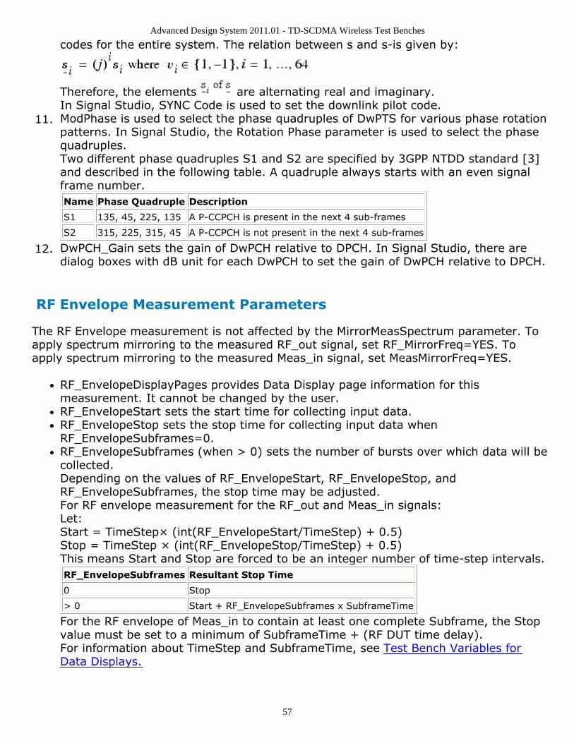
Advanced Design System 2011.01 - TD-SCDMA Wireless Test Benches
57
codes for the entire system. The relation between s and s-is given by:
Therefore, the elements are alternating real and imaginary.In Signal Studio, SYNC Code is used to set the downlink pilot code.ModPhase is used to select the phase quadruples of DwPTS for various phase rotation11.patterns. In Signal Studio, the Rotation Phase parameter is used to select the phasequadruples.Two different phase quadruples S1 and S2 are specified by 3GPP NTDD standard [3]and described in the following table. A quadruple always starts with an even signalframe number.Name Phase Quadruple Description
S1 135, 45, 225, 135 A P-CCPCH is present in the next 4 sub-frames
S2 315, 225, 315, 45 A P-CCPCH is not present in the next 4 sub-frames
DwPCH_Gain sets the gain of DwPCH relative to DPCH. In Signal Studio, there are12.dialog boxes with dB unit for each DwPCH to set the gain of DwPCH relative to DPCH.
RF Envelope Measurement Parameters
The RF Envelope measurement is not affected by the MirrorMeasSpectrum parameter. Toapply spectrum mirroring to the measured RF_out signal, set RF_MirrorFreq=YES. Toapply spectrum mirroring to the measured Meas_in signal, set MeasMirrorFreq=YES.
RF_EnvelopeDisplayPages provides Data Display page information for thismeasurement. It cannot be changed by the user.RF_EnvelopeStart sets the start time for collecting input data.RF_EnvelopeStop sets the stop time for collecting input data whenRF_EnvelopeSubframes=0.RF_EnvelopeSubframes (when > 0) sets the number of bursts over which data will becollected.Depending on the values of RF_EnvelopeStart, RF_EnvelopeStop, andRF_EnvelopeSubframes, the stop time may be adjusted.For RF envelope measurement for the RF_out and Meas_in signals:Let:Start = TimeStep× (int(RF_EnvelopeStart/TimeStep) + 0.5)Stop = TimeStep × (int(RF_EnvelopeStop/TimeStep) + 0.5)This means Start and Stop are forced to be an integer number of time-step intervals.RF_EnvelopeSubframes Resultant Stop Time
0 Stop
> 0 Start + RF_EnvelopeSubframes x SubframeTime
For the RF envelope of Meas_in to contain at least one complete Subframe, the Stopvalue must be set to a minimum of SubframeTime + (RF DUT time delay).For information about TimeStep and SubframeTime, see Test Bench Variables forData Displays.
Advanced Design System 2011.01 - TD-SCDMA Wireless Test Benches
58
Constellation Parameters
The Constellation measurement requires setting the MirrorMeasSpectrum parameter suchthat there is an even number of spectrum mirrorings from the combined test bench sourceand RF DUT. For example, if MirrorSourceSpectrum=NO and the RF DUT causes its outputRF signal to have spectrum mirroring relative to its input signal, then setMirrorMeasSpectrum=YES.
ConstellationDisplayPages provides Data Display page information for this1.measurement. It cannot be changed by the user.ConstellationSubframes sets the number of subframes over which data will be2.collected.The measurement start time is the time when the first subframe is detected in the3.measured RF signal. Automatic synchronization by the measurement model avoidsany start-up transient in the Constellation plots.
Power Measurement Parameters
PowerDisplayPages provides Data Display page information for this measurement. It1.cannot be changed by the user.PowerSubframeMeasured sets the number of subframes over which data will be2.collected.The measurement start time is the time when the first subframe is detected in the3.measured RF signal. Automatic synchronization by the measurement model avoidsany start-up transient in the Constellation plots. The measurement stop time is thisstart time plus PowerSubframeMeasured × SubframeTime. SubframeTime isdescribed in Test Bench Variables for Data Displays.
Spectrum Measurement Parameters
The Spectrum measurement calculates the spectrum of the input signal. Averaging thespectrum over multiple subframes can be enabled as described in this section.This measurement is not affected by the MirrorMeasSpectrum parameter. To applyspectrum mirroring to the measured RF_out signal, set RF_MirrorFreq = YES; to applyspectrum mirroring to the measured Meas_in signal, set MeasMirrorFreq = YES.In the following, TimeStep denotes the simulation time step and FMeasurement denotesthe measured RF signal characterization frequency.
The measurement outputs the complex amplitude voltage values at the frequencies1.of the spectral tones. It does not output the power at the frequencies of the spectraltones. However, one can calculate and display the power spectrum as well as themagnitude and phase spectrum by using the dBm, mag, and phase functions of thedata display window.Note that the dBm function assumes a 50-ohm reference resistance; if a differentmeasurement was used in the test bench, its value can be specified as a second
Advanced Design System 2011.01 - TD-SCDMA Wireless Test Benches
59
argument to the dBm function, for example, dBm(SpecMeas, Meas_RefR) whereSpecMeas is the instance name of the spectrum measurement and Meas_RefR is theresistive load used.By default, the displayed spectrum extends from FMeasurement - 1/(2×TimeStep) Hzto FMeasurement + 1/(2×TimeStep) Hz. When FMeasurement < 1/(2×TimeStep),the default spectrum extends to negative frequencies. The spectral content at thesenegative frequencies is conjugated, mirrored, and added to the spectral content ofthe closest positive frequency. The negative frequency tones are then displayed onthe positive frequency axis as would happen in an RF spectrum analyzermeasurement instrument. This process may introduce an error in the displayedfrequency for the mirrored tones. The absolute error introduced is less than(spectrum frequency step) / 2 (see Effect of Values for SpecMeasStart,SpecMeasStop, SpecMeasSubframes, and SpecMeasResBW for the definition ofspectrum frequency step).The basis of the algorithm used by the spectrum measurement is the chirp-Ztransform. The algorithm can use multiple subframes and average the results toachieve video averaging (see note 6).SpecMeasDisplayPages provides information regarding Data Display pages for this2.measurement. It cannot be changed by the user.SpecMeasStart sets the start time for collecting input data.3.SpecMeasStop sets the stop time for collecting input data when SpecMeasSubframes4.= 0 and SpecMeasResBW = 0.SpecMeasSubframes sets the number of segments over which data will be collected.5.SpecMeasResBW sets the resolution bandwidth of the spectrum.6.Depending on the values of SpecMeasStart, SpecMeasStop, SpecMeasSubframes, andSpecMeasResBW, the stop time may be adjusted or spectrum video averaging mayoccur (or both). The different cases are described in Effect of Values forSpecMeasStart, SpecMeasStop, SpecMeasSubframes, and SpecMeasResBW.Referring to Effect of Values for SpecMeasStart, SpecMeasStop, SpecMeasSubframes,and SpecMeasResBW, letStart = TimeStep × int((SpecMeasStart/TimeStep) + 0.5)Stop = TimeStep × int((SpecMeasStop/TimeStep) + 0.5)(This means Start and Stop are forced to be an integer number of time stepintervals.)X = normalized equivalent noise bandwidth of the windowStart and Stop times are used for RF_out and Meas_in signal spectrum analyses. TheMeas_in signal is delayed in time from the RF_out signal by the value of the RF DUTtime delay. Therefore, for RF DUT time delay >0, the RF_out and Meas_in signals areinherently different and spectrum display differences can be expected.TimeStep and SubframeTime are defined in the Test Bench Variables for DataDisplays section.Equivalent noise bandwidth (ENBW) compares the window to an ideal, rectangularfilter. It is the equivalent width of a rectangular filter that passes the same amount ofwhite noise as the window. Normalized ENBW (NENBW) is ENBW multiplied by theduration of the signal being windowed. (Refer to note 7 regarding the various windowoptions and Window Options and Normalized Equivalent Noise Bandwidth regardingNENBW for the various windows.)
Effect of Values for SpecMeasStart, SpecMeasStop, SpecMeasSubframes, and SpecMeasResBW
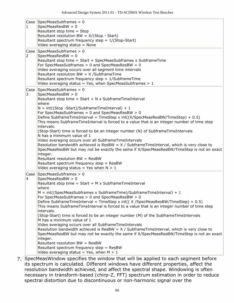
Advanced Design System 2011.01 - TD-SCDMA Wireless Test Benches
60
Case1
SpecMeasSubframes = 0SpecMeasResBW = 0Resultant stop time = StopResultant resolution BW = X/(Stop - Start)Resultant spectrum frequency step = 1/(Stop-Start)Video averaging status = None
Case2
SpecMeasSubframes > 0SpecMeasResBW = 0Resultant stop time = Start + SpecMeasSubframes x SubframeTimeFor SpecMeasSubframes > 0 and SpecMeasResBW = 0Video averaging occurs over all segment time intervalsResultant resolution BW = X /SubframeTimeResultant spectrum frequency step = 1/SubframeTimeVideo averaging status = Yes, when SpecMeasSubframes > 1
Case3
SpecMeasSubframes = 0SpecMeasResBW > 0Resultant stop time = Start + N x SubframeTimeIntervalwhereN = int((Stop -Start)/SubframeTimeInterval) + 1For SpecMeasSubframes = 0 and SpecMeasResBW > 0Define SubframeTimeInterval = TimeStep x int((X/SpecMeasResBW/TimeStep) + 0.5)This means SubframeTimeInterval is forced to a value that is an integer number of time stepintervals.(Stop-Start) time is forced to be an integer number (N) of SubframeTimeIntervalsN has a minimum value of 1Video averaging occurs over all SubframeTimeIntervalsResolution bandwidth achieved is ResBW = X / SubframeTimeInterval, which is very close toSpecMeasResBW but may not be exactly the same if X/SpecMeasResBW/TimeStep is not an exactinteger.Resultant resolution BW = ResBWResultant spectrum frequency step = ResBWVideo averaging status = Yes when N > 1
Case4
SpecMeasSubframes > 0SpecMeasResBW > 0Resultant stop time = Start + M x SubframeTimeIntervalwhereM = int((SpecMeasSubframes x SubframeTime)/SubframeTimeInterval) + 1For SpecMeasSubframes > 0 and SpecMeasResBW > 0Define SubframeTimeInterval = TimeStep x int(( X /SpecMeasResBW/TimeStep) + 0.5)This means SubframeTimeInterval is forced to a value that is an integer number of time stepintervals.(Stop-Start) time is forced to be an integer number (M) of the SubframeTimeIntervalsM has a minimum value of 1Video averaging occurs over all SubframeTimeIntervalsResolution bandwidth achieved is ResBW = X / SubframeTimeInterval, which is very close toSpecMeasResBW but may not be exactly the same if X/SpecMeasResBW/TimeStep is not an exactinteger.Resultant resolution BW = ResBWResultant spectrum frequency step = ResBWVideo averaging status = Yes, when M > 1
SpecMeasWindow specifies the window that will be applied to each segment before7.its spectrum is calculated. Different windows have different properties, affect theresolution bandwidth achieved, and affect the spectral shape. Windowing is oftennecessary in transform-based (chirp-Z, FFT) spectrum estimation in order to reducespectral distortion due to discontinuous or non-harmonic signal over the
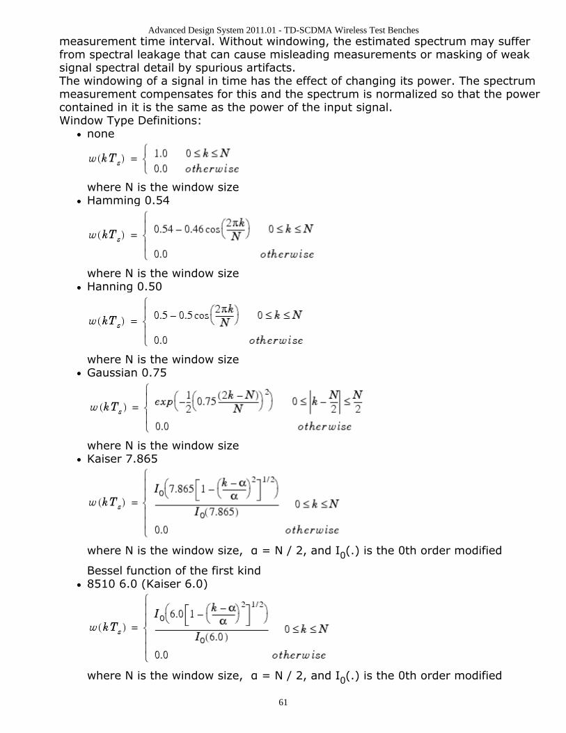
Advanced Design System 2011.01 - TD-SCDMA Wireless Test Benches
61
measurement time interval. Without windowing, the estimated spectrum may sufferfrom spectral leakage that can cause misleading measurements or masking of weaksignal spectral detail by spurious artifacts.The windowing of a signal in time has the effect of changing its power. The spectrummeasurement compensates for this and the spectrum is normalized so that the powercontained in it is the same as the power of the input signal.Window Type Definitions:
none
where N is the window sizeHamming 0.54
where N is the window sizeHanning 0.50
where N is the window sizeGaussian 0.75
where N is the window sizeKaiser 7.865
where N is the window size, α = N / 2, and I0(.) is the 0th order modified
Bessel function of the first kind8510 6.0 (Kaiser 6.0)
where N is the window size, α = N / 2, and I0(.) is the 0th order modified
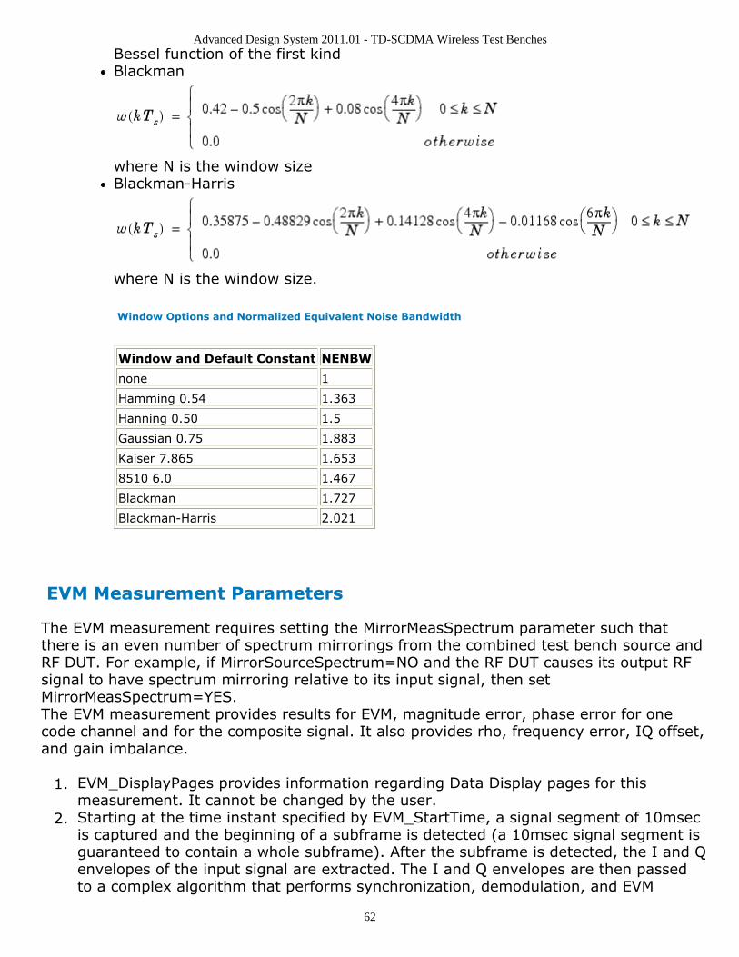
Advanced Design System 2011.01 - TD-SCDMA Wireless Test Benches
62
Bessel function of the first kindBlackman
where N is the window sizeBlackman-Harris
where N is the window size.
Window Options and Normalized Equivalent Noise Bandwidth
Window and Default Constant NENBW
none 1
Hamming 0.54 1.363
Hanning 0.50 1.5
Gaussian 0.75 1.883
Kaiser 7.865 1.653
8510 6.0 1.467
Blackman 1.727
Blackman-Harris 2.021
EVM Measurement Parameters
The EVM measurement requires setting the MirrorMeasSpectrum parameter such thatthere is an even number of spectrum mirrorings from the combined test bench source andRF DUT. For example, if MirrorSourceSpectrum=NO and the RF DUT causes its output RFsignal to have spectrum mirroring relative to its input signal, then setMirrorMeasSpectrum=YES.The EVM measurement provides results for EVM, magnitude error, phase error for onecode channel and for the composite signal. It also provides rho, frequency error, IQ offset,and gain imbalance.
EVM_DisplayPages provides information regarding Data Display pages for this1.measurement. It cannot be changed by the user.Starting at the time instant specified by EVM_StartTime, a signal segment of 10msec2.is captured and the beginning of a subframe is detected (a 10msec signal segment isguaranteed to contain a whole subframe). After the subframe is detected, the I and Qenvelopes of the input signal are extracted. The I and Q envelopes are then passedto a complex algorithm that performs synchronization, demodulation, and EVM
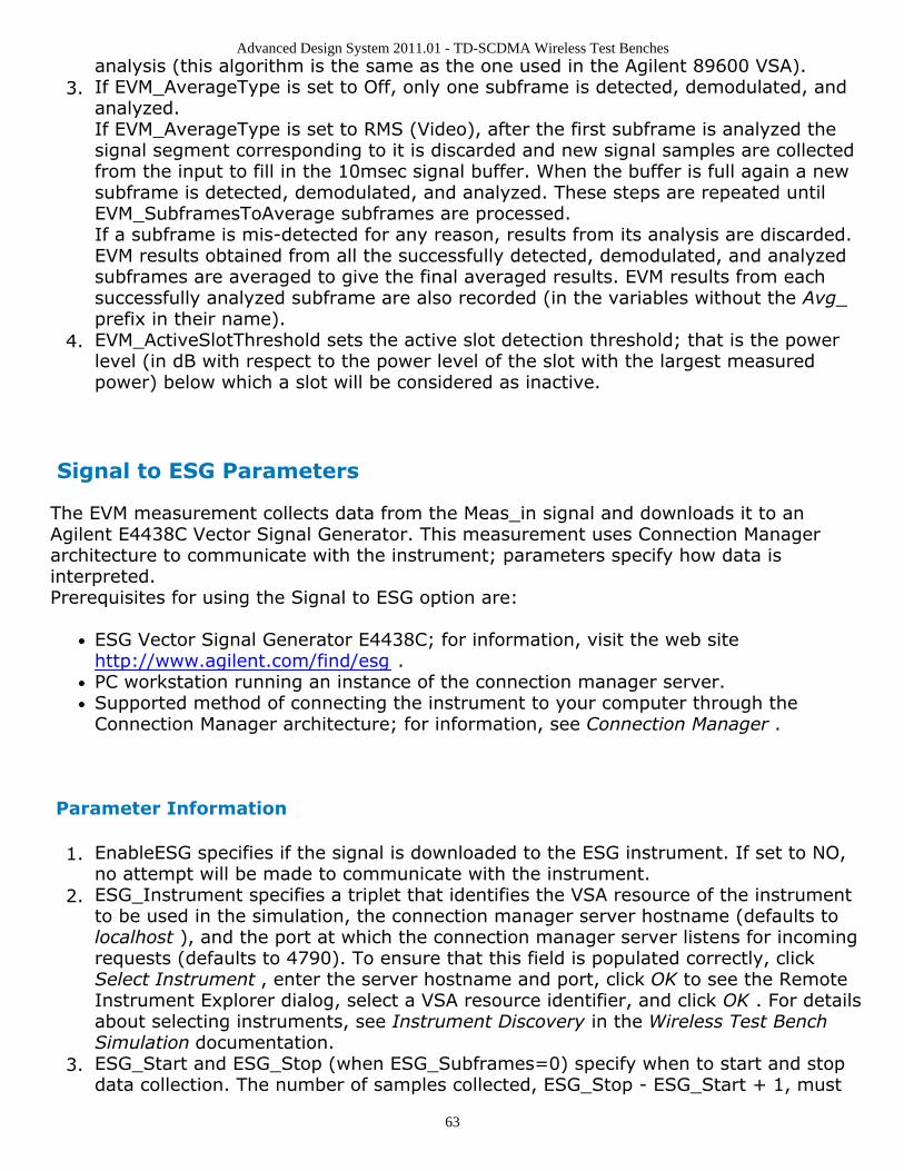
Advanced Design System 2011.01 - TD-SCDMA Wireless Test Benches
63
analysis (this algorithm is the same as the one used in the Agilent 89600 VSA).If EVM_AverageType is set to Off, only one subframe is detected, demodulated, and3.analyzed.If EVM_AverageType is set to RMS (Video), after the first subframe is analyzed thesignal segment corresponding to it is discarded and new signal samples are collectedfrom the input to fill in the 10msec signal buffer. When the buffer is full again a newsubframe is detected, demodulated, and analyzed. These steps are repeated untilEVM_SubframesToAverage subframes are processed.If a subframe is mis-detected for any reason, results from its analysis are discarded.EVM results obtained from all the successfully detected, demodulated, and analyzedsubframes are averaged to give the final averaged results. EVM results from eachsuccessfully analyzed subframe are also recorded (in the variables without the Avg_prefix in their name).EVM_ActiveSlotThreshold sets the active slot detection threshold; that is the power4.level (in dB with respect to the power level of the slot with the largest measuredpower) below which a slot will be considered as inactive.
Signal to ESG Parameters
The EVM measurement collects data from the Meas_in signal and downloads it to anAgilent E4438C Vector Signal Generator. This measurement uses Connection Managerarchitecture to communicate with the instrument; parameters specify how data isinterpreted.Prerequisites for using the Signal to ESG option are:
ESG Vector Signal Generator E4438C; for information, visit the web sitehttp://www.agilent.com/find/esg .PC workstation running an instance of the connection manager server.Supported method of connecting the instrument to your computer through theConnection Manager architecture; for information, see Connection Manager .
Parameter Information
EnableESG specifies if the signal is downloaded to the ESG instrument. If set to NO,1.no attempt will be made to communicate with the instrument.ESG_Instrument specifies a triplet that identifies the VSA resource of the instrument2.to be used in the simulation, the connection manager server hostname (defaults tolocalhost ), and the port at which the connection manager server listens for incomingrequests (defaults to 4790). To ensure that this field is populated correctly, clickSelect Instrument , enter the server hostname and port, click OK to see the RemoteInstrument Explorer dialog, select a VSA resource identifier, and click OK . For detailsabout selecting instruments, see Instrument Discovery in the Wireless Test BenchSimulation documentation.ESG_Start and ESG_Stop (when ESG_Subframes=0) specify when to start and stop3.data collection. The number of samples collected, ESG_Stop - ESG_Start + 1, must
Advanced Design System 2011.01 - TD-SCDMA Wireless Test Benches
64
be in the range 60 samples to 64 Msamples, where 1 Msample = 1,048,576 samples.The ESG requires an even number of samples; the last sample will be discarded ifESG_Stop - ESG_Start + 1 is odd.ESG_Subframes sets the number of subframes over which data will be collected. If4.ESG_Subframes is greater than zero, then ESG_Stop is forced to ESG_Start +ESG_Subframes x SubframeTime where SubframeTime is 5 msec.ESG_ClkRef specifies an internal or external reference for the ESG clock generator. If5.set to External, the ESG_ExtClkRefFreq parameter sets the frequency of this clock.ESG_IQFilter specifies the cutoff frequency for the reconstruction filter that lies6.between the DAC output and the Dual Arbitrary Waveform Generator output insidethe ESG.ESG_SampleClkRate sets the sample clock rate for the DAC output.7.ESG_Filename sets the name of the waveform inside the ESG that will hold the8.downloaded data.The ESG driver expects data in the range {-1, 1}. The ESG_AutoScaling parameter9.specifies whether to scale inputs to fit this range. If set to YES, inputs are scaled tothe range {-1, 1}; if set to NO, raw simulation data is downloaded to the ESGwithout any scaling, but data outside the range {-1, 1} is clipped to -1 or 1. If set toYES, scaling is also applied to data written to the local file (ESG_Filename setting).If ESG_ArbOn is set to YES, the ESG will start generating the signal immediately after10.simulation data is downloaded; if set to NO, waveform generation must be turned onat the ESG front panel.If ESG_RFPowOn is set to YES, the ESG will turn RF power on immediately after11.simulation data is downloaded. If ESG_RFPowOn is set to NO (default), RF powermust be turned on at the ESG front panel.ESG_EventMarkerType specifies which ESG Event markers are enabled: Event1,12.Event2, Both, or Neither. Event markers are used for synchronizing other instrumentsto the ESG. When event markers are enabled, Event1 or Event2 (or both) is setbeginning from the first sample of the downloaded Arb waveform over the range ofpoints specified by the ESG_MarkerLength parameter. This is equivalent to settingthe corresponding event from the front panel of the ESG.ESG_MarkerLength specifies the range of points over which the markers must be set13.starting from the first point of the waveform. Depending on theESG_EventMarkerType setting, the trigger length of Event1 or Event2 (or both) is setto a multiple of the pulsewidth that, in turn, is determined by the sample clock rateof the DAC output.
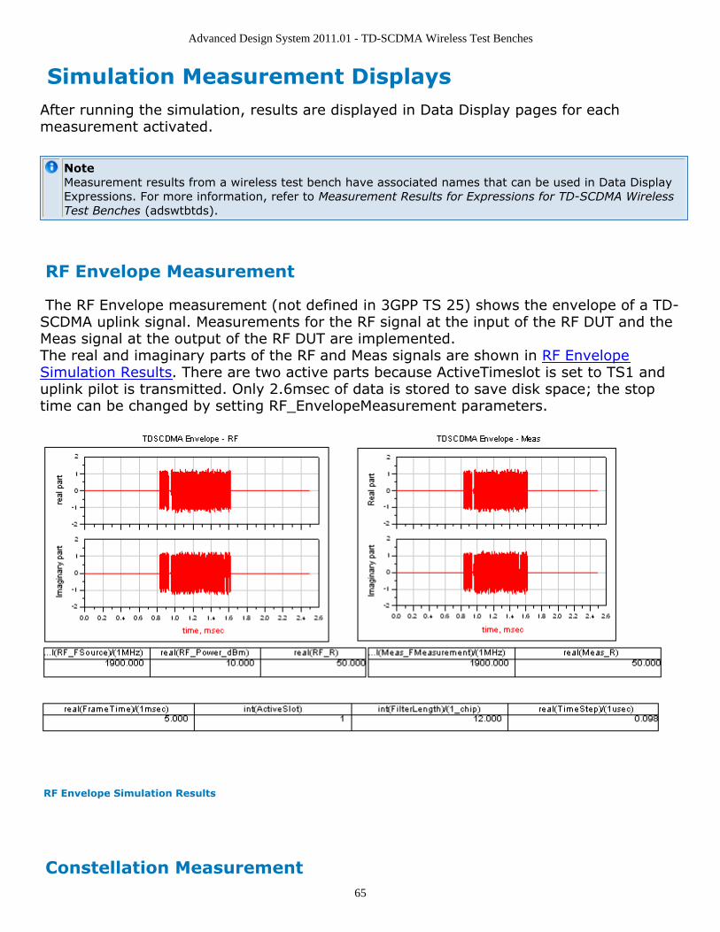
Advanced Design System 2011.01 - TD-SCDMA Wireless Test Benches
65
Simulation Measurement DisplaysAfter running the simulation, results are displayed in Data Display pages for eachmeasurement activated.
NoteMeasurement results from a wireless test bench have associated names that can be used in Data DisplayExpressions. For more information, refer to Measurement Results for Expressions for TD-SCDMA WirelessTest Benches (adswtbtds).
RF Envelope Measurement
The RF Envelope measurement (not defined in 3GPP TS 25) shows the envelope of a TD-SCDMA uplink signal. Measurements for the RF signal at the input of the RF DUT and theMeas signal at the output of the RF DUT are implemented.The real and imaginary parts of the RF and Meas signals are shown in RF EnvelopeSimulation Results. There are two active parts because ActiveTimeslot is set to TS1 anduplink pilot is transmitted. Only 2.6msec of data is stored to save disk space; the stoptime can be changed by setting RF_EnvelopeMeasurement parameters.
RF Envelope Simulation Results
Constellation Measurement
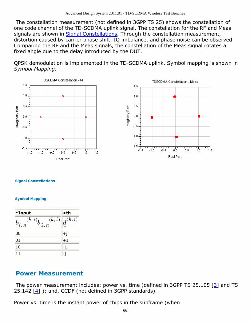
Advanced Design System 2011.01 - TD-SCDMA Wireless Test Benches
66
The constellation measurement (not defined in 3GPP TS 25) shows the constellation ofone code channel of the TD-SCDMA uplink signal. The constellation for the RF and Meassignals are shown in Signal Constellations. Through the constellation measurement,distortion caused by carrier phase shift, IQ imbalance, and phase noise can be observed.Comparing the RF and the Meas signals, the constellation of the Meas signal rotates afixed angle due to the delay introduced by the DUT.
QPSK demodulation is implemented in the TD-SCDMA uplink. Symbol mapping is shown inSymbol Mapping.
Signal Constellations
Symbol Mapping
*Input <th
00 +j
01 +1
10 -1
11 -j
Power Measurement
The power measurement includes: power vs. time (defined in 3GPP TS 25.105 [3] and TS25.142 [4] ); and, CCDF (not defined in 3GPP standards).
Power vs. time is the instant power of chips in the subframe (when
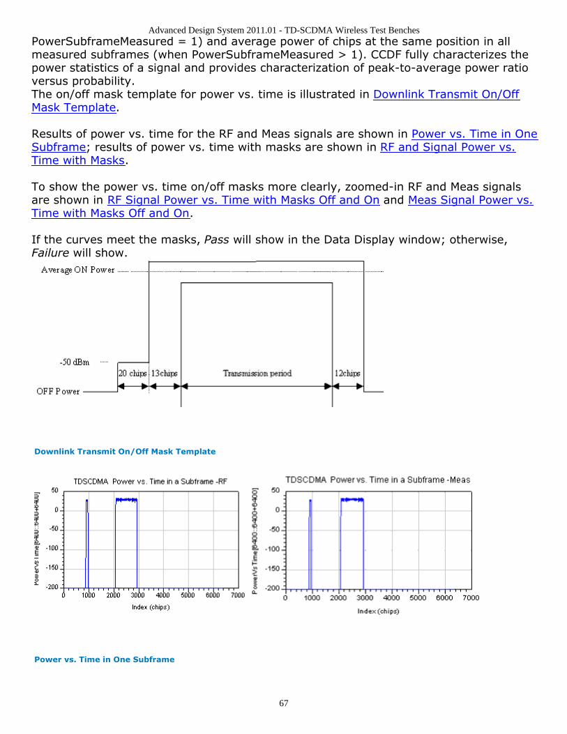
Advanced Design System 2011.01 - TD-SCDMA Wireless Test Benches
67
PowerSubframeMeasured = 1) and average power of chips at the same position in allmeasured subframes (when PowerSubframeMeasured > 1). CCDF fully characterizes thepower statistics of a signal and provides characterization of peak-to-average power ratioversus probability.The on/off mask template for power vs. time is illustrated in Downlink Transmit On/OffMask Template.
Results of power vs. time for the RF and Meas signals are shown in Power vs. Time in OneSubframe; results of power vs. time with masks are shown in RF and Signal Power vs.Time with Masks.
To show the power vs. time on/off masks more clearly, zoomed-in RF and Meas signalsare shown in RF Signal Power vs. Time with Masks Off and On and Meas Signal Power vs.Time with Masks Off and On.
If the curves meet the masks, Pass will show in the Data Display window; otherwise,Failure will show.
Downlink Transmit On/Off Mask Template
Power vs. Time in One Subframe
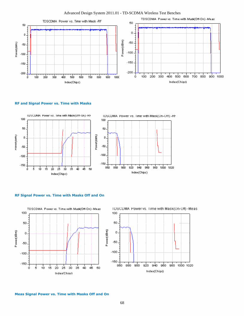
Advanced Design System 2011.01 - TD-SCDMA Wireless Test Benches
68
RF and Signal Power vs. Time with Masks
RF Signal Power vs. Time with Masks Off and On
Meas Signal Power vs. Time with Masks Off and On
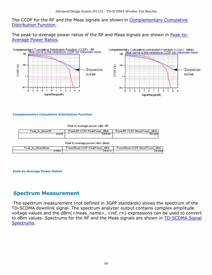
Advanced Design System 2011.01 - TD-SCDMA Wireless Test Benches
69
The CCDF for the RF and the Meas signals are shown in Complementary CumulativeDistribution Function.
The peak-to-average power ratios of the RF and Meas signals are shown in Peak-to-Average Power Ratios.
Complementary Cumulative Distribution Function
Peak-to-Average Power Ratios
Spectrum Measurement
The spectrum measurement (not defined in 3GPP standards) shows the spectrum of theTD-SCDMA downlink signal. The spectrum analyzer output contains complex amplitudevoltage values and the dBm(<meas_name>, <ref_r>) expressions can be used to convertto dBm values. Spectrums for the RF and the Meas signals are shown in TD-SCDMA SignalSpectrums.
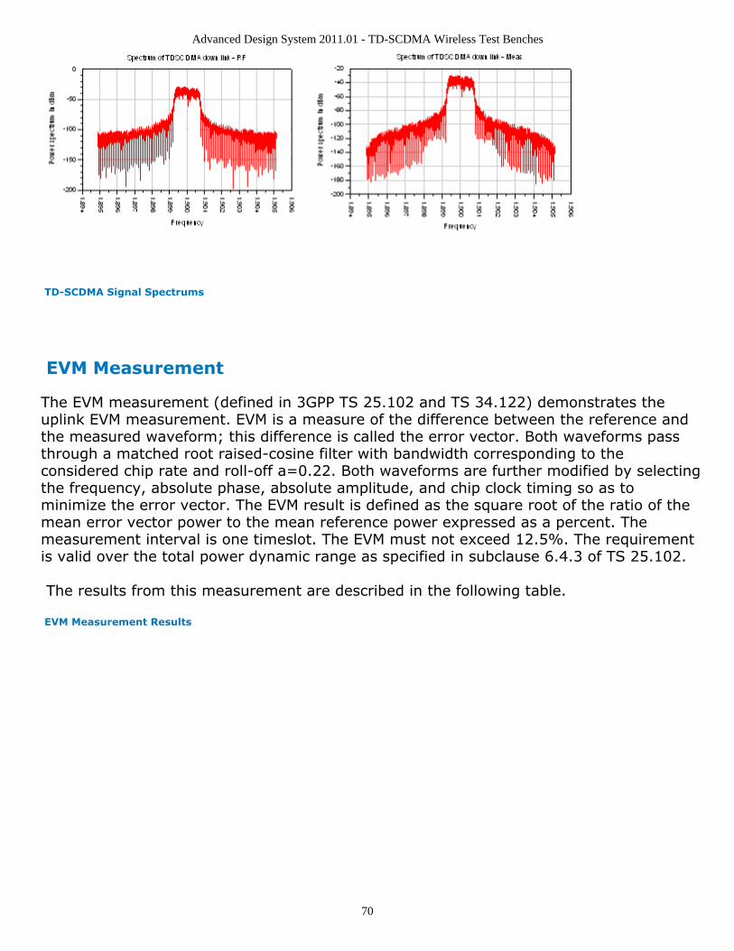
Advanced Design System 2011.01 - TD-SCDMA Wireless Test Benches
70
TD-SCDMA Signal Spectrums
EVM Measurement
The EVM measurement (defined in 3GPP TS 25.102 and TS 34.122) demonstrates theuplink EVM measurement. EVM is a measure of the difference between the reference andthe measured waveform; this difference is called the error vector. Both waveforms passthrough a matched root raised-cosine filter with bandwidth corresponding to theconsidered chip rate and roll-off a=0.22. Both waveforms are further modified by selectingthe frequency, absolute phase, absolute amplitude, and chip clock timing so as tominimize the error vector. The EVM result is defined as the square root of the ratio of themean error vector power to the mean reference power expressed as a percent. Themeasurement interval is one timeslot. The EVM must not exceed 12.5%. The requirementis valid over the total power dynamic range as specified in subclause 6.4.3 of TS 25.102.
The results from this measurement are described in the following table.
EVM Measurement Results
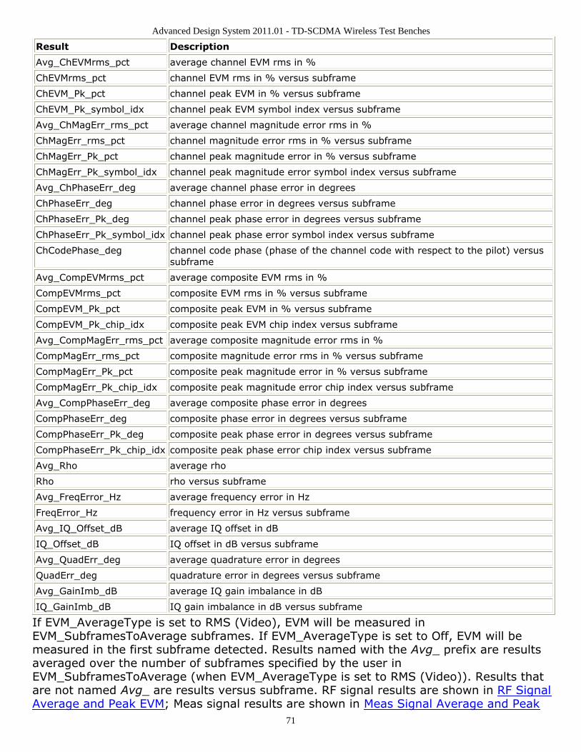
Advanced Design System 2011.01 - TD-SCDMA Wireless Test Benches
71
Result Description
Avg_ChEVMrms_pct average channel EVM rms in %
ChEVMrms_pct channel EVM rms in % versus subframe
ChEVM_Pk_pct channel peak EVM in % versus subframe
ChEVM_Pk_symbol_idx channel peak EVM symbol index versus subframe
Avg_ChMagErr_rms_pct average channel magnitude error rms in %
ChMagErr_rms_pct channel magnitude error rms in % versus subframe
ChMagErr_Pk_pct channel peak magnitude error in % versus subframe
ChMagErr_Pk_symbol_idx channel peak magnitude error symbol index versus subframe
Avg_ChPhaseErr_deg average channel phase error in degrees
ChPhaseErr_deg channel phase error in degrees versus subframe
ChPhaseErr_Pk_deg channel peak phase error in degrees versus subframe
ChPhaseErr_Pk_symbol_idx channel peak phase error symbol index versus subframe
ChCodePhase_deg channel code phase (phase of the channel code with respect to the pilot) versussubframe
Avg_CompEVMrms_pct average composite EVM rms in %
CompEVMrms_pct composite EVM rms in % versus subframe
CompEVM_Pk_pct composite peak EVM in % versus subframe
CompEVM_Pk_chip_idx composite peak EVM chip index versus subframe
Avg_CompMagErr_rms_pct average composite magnitude error rms in %
CompMagErr_rms_pct composite magnitude error rms in % versus subframe
CompMagErr_Pk_pct composite peak magnitude error in % versus subframe
CompMagErr_Pk_chip_idx composite peak magnitude error chip index versus subframe
Avg_CompPhaseErr_deg average composite phase error in degrees
CompPhaseErr_deg composite phase error in degrees versus subframe
CompPhaseErr_Pk_deg composite peak phase error in degrees versus subframe
CompPhaseErr_Pk_chip_idx composite peak phase error chip index versus subframe
Avg_Rho average rho
Rho rho versus subframe
Avg_FreqError_Hz average frequency error in Hz
FreqError_Hz frequency error in Hz versus subframe
Avg_IQ_Offset_dB average IQ offset in dB
IQ_Offset_dB IQ offset in dB versus subframe
Avg_QuadErr_deg average quadrature error in degrees
QuadErr_deg quadrature error in degrees versus subframe
Avg_GainImb_dB average IQ gain imbalance in dB
IQ_GainImb_dB IQ gain imbalance in dB versus subframe
If EVM_AverageType is set to RMS (Video), EVM will be measured inEVM_SubframesToAverage subframes. If EVM_AverageType is set to Off, EVM will bemeasured in the first subframe detected. Results named with the Avg_ prefix are resultsaveraged over the number of subframes specified by the user inEVM_SubframesToAverage (when EVM_AverageType is set to RMS (Video)). Results thatare not named Avg_ are results versus subframe. RF signal results are shown in RF SignalAverage and Peak EVM; Meas signal results are shown in Meas Signal Average and Peak
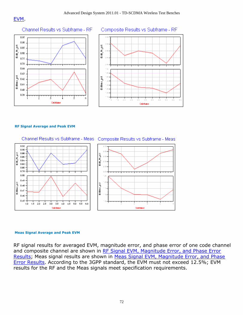
Advanced Design System 2011.01 - TD-SCDMA Wireless Test Benches
72
EVM.
RF Signal Average and Peak EVM
Meas Signal Average and Peak EVM
RF signal results for averaged EVM, magnitude error, and phase error of one code channeland composite channel are shown in RF Signal EVM, Magnitude Error, and Phase ErrorResults; Meas signal results are shown in Meas Signal EVM, Magnitude Error, and PhaseError Results. According to the 3GPP standard, the EVM must not exceed 12.5%; EVMresults for the RF and the Meas signals meet specification requirements.
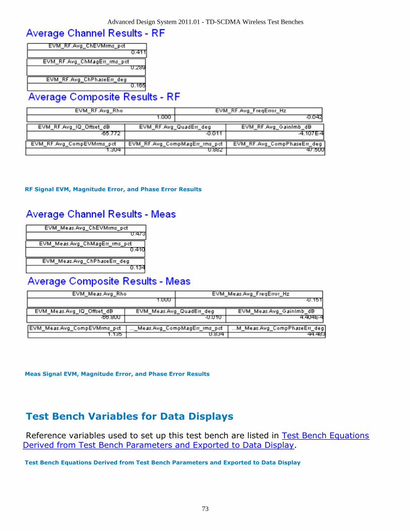
Advanced Design System 2011.01 - TD-SCDMA Wireless Test Benches
73
RF Signal EVM, Magnitude Error, and Phase Error Results
Meas Signal EVM, Magnitude Error, and Phase Error Results
Test Bench Variables for Data Displays
Reference variables used to set up this test bench are listed in Test Bench EquationsDerived from Test Bench Parameters and Exported to Data Display.
Test Bench Equations Derived from Test Bench Parameters and Exported to Data Display
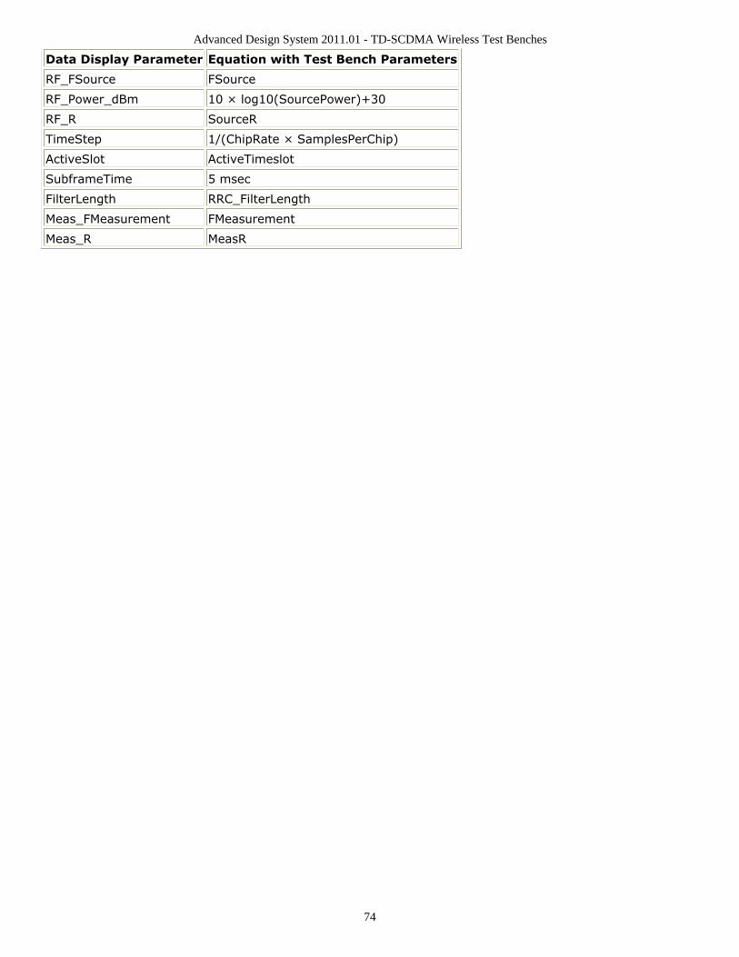
Advanced Design System 2011.01 - TD-SCDMA Wireless Test Benches
74
Data Display Parameter Equation with Test Bench Parameters
RF_FSource FSource
RF_Power_dBm 10 × log10(SourcePower)+30
RF_R SourceR
TimeStep 1/(ChipRate × SamplesPerChip)
ActiveSlot ActiveTimeslot
SubframeTime 5 msec
FilterLength RRC_FilterLength
Meas_FMeasurement FMeasurement
Meas_R MeasR

Advanced Design System 2011.01 - TD-SCDMA Wireless Test Benches
75
Baseline PerformanceTest Computer Configuration
Pentium IV 2.4 GHz, 512 MB RAM, Red Hat Linux 7.3Conditions
Measurements made with default test bench settings.RF DUT is an RF system behavior component.The number of time points in one TD-SCDMA downlink subframe is a function ofSamplesPerChip and ChipRate.SamplesPerChip = 8ChipRate = 1.28 Mb/sResultant WTB_TimeStep = 97.65625 nsec; SubframeTime = 5msec; timepoints per subframe = 51200.
Simulation times and memory requirements:TDSCDMA_DnLnk_TXMeasurement
BurstsMeasured
Simulation Time(sec)
ADS Processes(MB)
RF_Envelope 1 14 125
Constellation 3 17 124
Power 3 175 122
Spectrum 3 24 142
EVM 3 13 108
Expected ADS Performance
Expected ADS performance is the combined performance of the baseline test bench andthe RF DUT Circuit Envelope simulation with the same signal and number of time points.For example, if the RF DUT performance with Circuit Envelope simulation alone takes 2hours and consumes 200 MB of memory (excluding the memory consumed by the coreADS product), then add these numbers to the Baseline Performance numbers todetermine the expected ADS performance. This is valid only if the full memory consumedis from RAM. If RAM is less, larger simulation times may result due to increased diskaccess time for swap memory usage.
Advanced Design System 2011.01 - TD-SCDMA Wireless Test Benches
76
References for Downlink Transmitter Test3GPP TS 25.221, "3rd Generation Partnership Project; Technical Specification Group1.Radio Access Network; Physical channels and mapping of transport channels ontophysical channels (TDD) (Release 4)," version 4.5.0, June, 2002.http://www.3gpp.org/ftp/Specs/2002-06/Rel-4/25_series/25221-450.zip ]3GPP TS 25.223, "3rd Generation Partnership Project; Technical Specification Group2.Radio Access Network; Spreading and modulation (TDD) (Release 4)," version 4.4.0,March, 2002.http://www.3gpp.org/ftp/Specs/2002-06/Rel-4/25_series/25223-440.zip ]3GPP TS 25.105, "3rd Generation Partnership Project; Technical Specification Group3.Radio Access Networks; BS Radio transmission and Reception (TDD) (Release 4),"version 4.5.0, June, 2002.http://www.3gpp.org/ftp/Specs/2002-06/Rel-4/25_series/25105-450.zip ]3GPP TS 25.142 V4.5.0 "3rd Generation Partnership Project; Technical Specification4.Group Radio Access Networks; Base station conformance testing (TDD) (Release 4),"version 4.5.0, June, 2002.http://www.3gpp.org/ftp/Specs/2002-06/Rel-4/25_series/25142-450.zip ]Setting up a Wireless Test Bench Analysis in the Wireless Test Bench Simulationdocumentation explains how to use test bench windows and dialogs to performanalysis tasks.Setting Circuit Envelope Analysis Parameters in the Wireless Test Bench Simulationdocumentation explains how to set up circuit envelope analysis parameters such asconvergence criteria, solver selection, and initial guess.Setting Automatic Verification Modeling Parameters in the Wireless Test BenchSimulation documentation explains how to improve simulation speed.
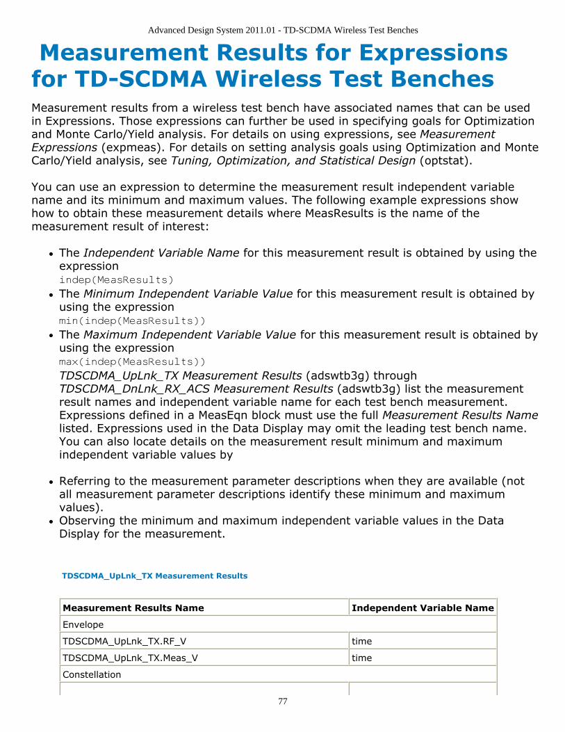
Advanced Design System 2011.01 - TD-SCDMA Wireless Test Benches
77
Measurement Results for Expressionsfor TD-SCDMA Wireless Test BenchesMeasurement results from a wireless test bench have associated names that can be usedin Expressions. Those expressions can further be used in specifying goals for Optimizationand Monte Carlo/Yield analysis. For details on using expressions, see MeasurementExpressions (expmeas). For details on setting analysis goals using Optimization and MonteCarlo/Yield analysis, see Tuning, Optimization, and Statistical Design (optstat).
You can use an expression to determine the measurement result independent variablename and its minimum and maximum values. The following example expressions showhow to obtain these measurement details where MeasResults is the name of themeasurement result of interest:
The Independent Variable Name for this measurement result is obtained by using theexpressionindep(MeasResults)
The Minimum Independent Variable Value for this measurement result is obtained byusing the expressionmin(indep(MeasResults))
The Maximum Independent Variable Value for this measurement result is obtained byusing the expressionmax(indep(MeasResults))
TDSCDMA_UpLnk_TX Measurement Results (adswtb3g) throughTDSCDMA_DnLnk_RX_ACS Measurement Results (adswtb3g) list the measurementresult names and independent variable name for each test bench measurement.Expressions defined in a MeasEqn block must use the full Measurement Results Namelisted. Expressions used in the Data Display may omit the leading test bench name.You can also locate details on the measurement result minimum and maximumindependent variable values by
Referring to the measurement parameter descriptions when they are available (notall measurement parameter descriptions identify these minimum and maximumvalues).Observing the minimum and maximum independent variable values in the DataDisplay for the measurement.
TDSCDMA_UpLnk_TX Measurement Results
Measurement Results Name Independent Variable Name
Envelope
TDSCDMA_UpLnk_TX.RF_V time
TDSCDMA_UpLnk_TX.Meas_V time
Constellation
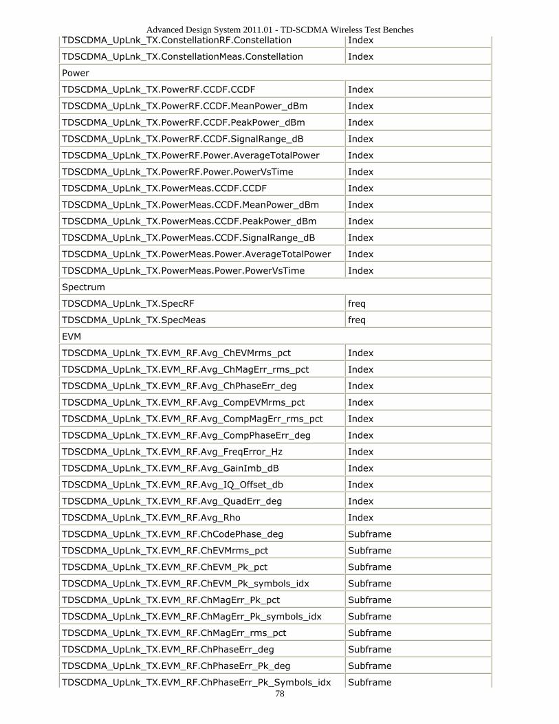
Advanced Design System 2011.01 - TD-SCDMA Wireless Test Benches
78
TDSCDMA_UpLnk_TX.ConstellationRF.Constellation Index
TDSCDMA_UpLnk_TX.ConstellationMeas.Constellation Index
Power
TDSCDMA_UpLnk_TX.PowerRF.CCDF.CCDF Index
TDSCDMA_UpLnk_TX.PowerRF.CCDF.MeanPower_dBm Index
TDSCDMA_UpLnk_TX.PowerRF.CCDF.PeakPower_dBm Index
TDSCDMA_UpLnk_TX.PowerRF.CCDF.SignalRange_dB Index
TDSCDMA_UpLnk_TX.PowerRF.Power.AverageTotalPower Index
TDSCDMA_UpLnk_TX.PowerRF.Power.PowerVsTime Index
TDSCDMA_UpLnk_TX.PowerMeas.CCDF.CCDF Index
TDSCDMA_UpLnk_TX.PowerMeas.CCDF.MeanPower_dBm Index
TDSCDMA_UpLnk_TX.PowerMeas.CCDF.PeakPower_dBm Index
TDSCDMA_UpLnk_TX.PowerMeas.CCDF.SignalRange_dB Index
TDSCDMA_UpLnk_TX.PowerMeas.Power.AverageTotalPower Index
TDSCDMA_UpLnk_TX.PowerMeas.Power.PowerVsTime Index
Spectrum
TDSCDMA_UpLnk_TX.SpecRF freq
TDSCDMA_UpLnk_TX.SpecMeas freq
EVM
TDSCDMA_UpLnk_TX.EVM_RF.Avg_ChEVMrms_pct Index
TDSCDMA_UpLnk_TX.EVM_RF.Avg_ChMagErr_rms_pct Index
TDSCDMA_UpLnk_TX.EVM_RF.Avg_ChPhaseErr_deg Index
TDSCDMA_UpLnk_TX.EVM_RF.Avg_CompEVMrms_pct Index
TDSCDMA_UpLnk_TX.EVM_RF.Avg_CompMagErr_rms_pct Index
TDSCDMA_UpLnk_TX.EVM_RF.Avg_CompPhaseErr_deg Index
TDSCDMA_UpLnk_TX.EVM_RF.Avg_FreqError_Hz Index
TDSCDMA_UpLnk_TX.EVM_RF.Avg_GainImb_dB Index
TDSCDMA_UpLnk_TX.EVM_RF.Avg_IQ_Offset_db Index
TDSCDMA_UpLnk_TX.EVM_RF.Avg_QuadErr_deg Index
TDSCDMA_UpLnk_TX.EVM_RF.Avg_Rho Index
TDSCDMA_UpLnk_TX.EVM_RF.ChCodePhase_deg Subframe
TDSCDMA_UpLnk_TX.EVM_RF.ChEVMrms_pct Subframe
TDSCDMA_UpLnk_TX.EVM_RF.ChEVM_Pk_pct Subframe
TDSCDMA_UpLnk_TX.EVM_RF.ChEVM_Pk_symbols_idx Subframe
TDSCDMA_UpLnk_TX.EVM_RF.ChMagErr_Pk_pct Subframe
TDSCDMA_UpLnk_TX.EVM_RF.ChMagErr_Pk_symbols_idx Subframe
TDSCDMA_UpLnk_TX.EVM_RF.ChMagErr_rms_pct Subframe
TDSCDMA_UpLnk_TX.EVM_RF.ChPhaseErr_deg Subframe
TDSCDMA_UpLnk_TX.EVM_RF.ChPhaseErr_Pk_deg Subframe
TDSCDMA_UpLnk_TX.EVM_RF.ChPhaseErr_Pk_Symbols_idx Subframe
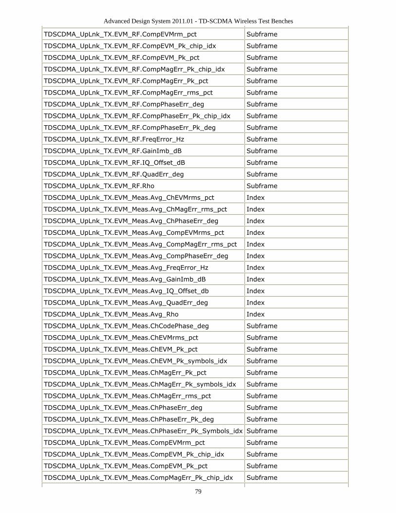
Advanced Design System 2011.01 - TD-SCDMA Wireless Test Benches
79
TDSCDMA_UpLnk_TX.EVM_RF.CompEVMrm_pct Subframe
TDSCDMA_UpLnk_TX.EVM_RF.CompEVM_Pk_chip_idx Subframe
TDSCDMA_UpLnk_TX.EVM_RF.CompEVM_Pk_pct Subframe
TDSCDMA_UpLnk_TX.EVM_RF.CompMagErr_Pk_chip_idx Subframe
TDSCDMA_UpLnk_TX.EVM_RF.CompMagErr_Pk_pct Subframe
TDSCDMA_UpLnk_TX.EVM_RF.CompMagErr_rms_pct Subframe
TDSCDMA_UpLnk_TX.EVM_RF.CompPhaseErr_deg Subframe
TDSCDMA_UpLnk_TX.EVM_RF.CompPhaseErr_Pk_chip_idx Subframe
TDSCDMA_UpLnk_TX.EVM_RF.CompPhaseErr_Pk_deg Subframe
TDSCDMA_UpLnk_TX.EVM_RF.FreqError_Hz Subframe
TDSCDMA_UpLnk_TX.EVM_RF.GainImb_dB Subframe
TDSCDMA_UpLnk_TX.EVM_RF.IQ_Offset_dB Subframe
TDSCDMA_UpLnk_TX.EVM_RF.QuadErr_deg Subframe
TDSCDMA_UpLnk_TX.EVM_RF.Rho Subframe
TDSCDMA_UpLnk_TX.EVM_Meas.Avg_ChEVMrms_pct Index
TDSCDMA_UpLnk_TX.EVM_Meas.Avg_ChMagErr_rms_pct Index
TDSCDMA_UpLnk_TX.EVM_Meas.Avg_ChPhaseErr_deg Index
TDSCDMA_UpLnk_TX.EVM_Meas.Avg_CompEVMrms_pct Index
TDSCDMA_UpLnk_TX.EVM_Meas.Avg_CompMagErr_rms_pct Index
TDSCDMA_UpLnk_TX.EVM_Meas.Avg_CompPhaseErr_deg Index
TDSCDMA_UpLnk_TX.EVM_Meas.Avg_FreqError_Hz Index
TDSCDMA_UpLnk_TX.EVM_Meas.Avg_GainImb_dB Index
TDSCDMA_UpLnk_TX.EVM_Meas.Avg_IQ_Offset_db Index
TDSCDMA_UpLnk_TX.EVM_Meas.Avg_QuadErr_deg Index
TDSCDMA_UpLnk_TX.EVM_Meas.Avg_Rho Index
TDSCDMA_UpLnk_TX.EVM_Meas.ChCodePhase_deg Subframe
TDSCDMA_UpLnk_TX.EVM_Meas.ChEVMrms_pct Subframe
TDSCDMA_UpLnk_TX.EVM_Meas.ChEVM_Pk_pct Subframe
TDSCDMA_UpLnk_TX.EVM_Meas.ChEVM_Pk_symbols_idx Subframe
TDSCDMA_UpLnk_TX.EVM_Meas.ChMagErr_Pk_pct Subframe
TDSCDMA_UpLnk_TX.EVM_Meas.ChMagErr_Pk_symbols_idx Subframe
TDSCDMA_UpLnk_TX.EVM_Meas.ChMagErr_rms_pct Subframe
TDSCDMA_UpLnk_TX.EVM_Meas.ChPhaseErr_deg Subframe
TDSCDMA_UpLnk_TX.EVM_Meas.ChPhaseErr_Pk_deg Subframe
TDSCDMA_UpLnk_TX.EVM_Meas.ChPhaseErr_Pk_Symbols_idx Subframe
TDSCDMA_UpLnk_TX.EVM_Meas.CompEVMrm_pct Subframe
TDSCDMA_UpLnk_TX.EVM_Meas.CompEVM_Pk_chip_idx Subframe
TDSCDMA_UpLnk_TX.EVM_Meas.CompEVM_Pk_pct Subframe
TDSCDMA_UpLnk_TX.EVM_Meas.CompMagErr_Pk_chip_idx Subframe
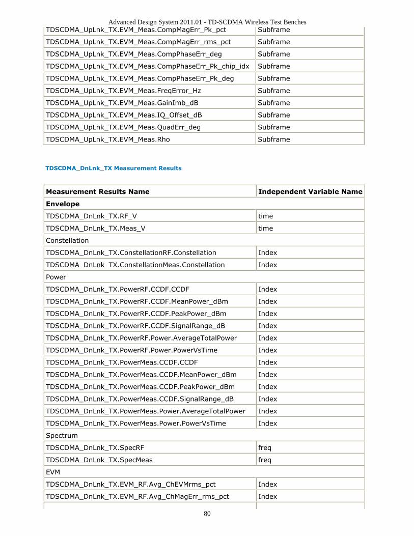
Advanced Design System 2011.01 - TD-SCDMA Wireless Test Benches
80
TDSCDMA_UpLnk_TX.EVM_Meas.CompMagErr_Pk_pct Subframe
TDSCDMA_UpLnk_TX.EVM_Meas.CompMagErr_rms_pct Subframe
TDSCDMA_UpLnk_TX.EVM_Meas.CompPhaseErr_deg Subframe
TDSCDMA_UpLnk_TX.EVM_Meas.CompPhaseErr_Pk_chip_idx Subframe
TDSCDMA_UpLnk_TX.EVM_Meas.CompPhaseErr_Pk_deg Subframe
TDSCDMA_UpLnk_TX.EVM_Meas.FreqError_Hz Subframe
TDSCDMA_UpLnk_TX.EVM_Meas.GainImb_dB Subframe
TDSCDMA_UpLnk_TX.EVM_Meas.IQ_Offset_dB Subframe
TDSCDMA_UpLnk_TX.EVM_Meas.QuadErr_deg Subframe
TDSCDMA_UpLnk_TX.EVM_Meas.Rho Subframe
TDSCDMA_DnLnk_TX Measurement Results
Measurement Results Name Independent Variable Name
Envelope
TDSCDMA_DnLnk_TX.RF_V time
TDSCDMA_DnLnk_TX.Meas_V time
Constellation
TDSCDMA_DnLnk_TX.ConstellationRF.Constellation Index
TDSCDMA_DnLnk_TX.ConstellationMeas.Constellation Index
Power
TDSCDMA_DnLnk_TX.PowerRF.CCDF.CCDF Index
TDSCDMA_DnLnk_TX.PowerRF.CCDF.MeanPower_dBm Index
TDSCDMA_DnLnk_TX.PowerRF.CCDF.PeakPower_dBm Index
TDSCDMA_DnLnk_TX.PowerRF.CCDF.SignalRange_dB Index
TDSCDMA_DnLnk_TX.PowerRF.Power.AverageTotalPower Index
TDSCDMA_DnLnk_TX.PowerRF.Power.PowerVsTime Index
TDSCDMA_DnLnk_TX.PowerMeas.CCDF.CCDF Index
TDSCDMA_DnLnk_TX.PowerMeas.CCDF.MeanPower_dBm Index
TDSCDMA_DnLnk_TX.PowerMeas.CCDF.PeakPower_dBm Index
TDSCDMA_DnLnk_TX.PowerMeas.CCDF.SignalRange_dB Index
TDSCDMA_DnLnk_TX.PowerMeas.Power.AverageTotalPower Index
TDSCDMA_DnLnk_TX.PowerMeas.Power.PowerVsTime Index
Spectrum
TDSCDMA_DnLnk_TX.SpecRF freq
TDSCDMA_DnLnk_TX.SpecMeas freq
EVM
TDSCDMA_DnLnk_TX.EVM_RF.Avg_ChEVMrms_pct Index
TDSCDMA_DnLnk_TX.EVM_RF.Avg_ChMagErr_rms_pct Index
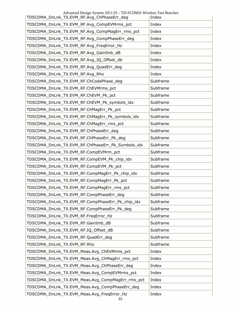
Advanced Design System 2011.01 - TD-SCDMA Wireless Test Benches
81
TDSCDMA_DnLnk_TX.EVM_RF.Avg_ChPhaseErr_deg Index
TDSCDMA_DnLnk_TX.EVM_RF.Avg_CompEVMrms_pct Index
TDSCDMA_DnLnk_TX.EVM_RF.Avg_CompMagErr_rms_pct Index
TDSCDMA_DnLnk_TX.EVM_RF.Avg_CompPhaseErr_deg Index
TDSCDMA_DnLnk_TX.EVM_RF.Avg_FreqError_Hz Index
TDSCDMA_DnLnk_TX.EVM_RF.Avg_GainImb_dB Index
TDSCDMA_DnLnk_TX.EVM_RF.Avg_IQ_Offset_db Index
TDSCDMA_DnLnk_TX.EVM_RF.Avg_QuadErr_deg Index
TDSCDMA_DnLnk_TX.EVM_RF.Avg_Rho Index
TDSCDMA_DnLnk_TX.EVM_RF.ChCodePhase_deg Subframe
TDSCDMA_DnLnk_TX.EVM_RF.ChEVMrms_pct Subframe
TDSCDMA_DnLnk_TX.EVM_RF.ChEVM_Pk_pct Subframe
TDSCDMA_DnLnk_TX.EVM_RF.ChEVM_Pk_symbols_idx Subframe
TDSCDMA_DnLnk_TX.EVM_RF.ChMagErr_Pk_pct Subframe
TDSCDMA_DnLnk_TX.EVM_RF.ChMagErr_Pk_symbols_idx Subframe
TDSCDMA_DnLnk_TX.EVM_RF.ChMagErr_rms_pct Subframe
TDSCDMA_DnLnk_TX.EVM_RF.ChPhaseErr_deg Subframe
TDSCDMA_DnLnk_TX.EVM_RF.ChPhaseErr_Pk_deg Subframe
TDSCDMA_DnLnk_TX.EVM_RF.ChPhaseErr_Pk_Symbols_idx Subframe
TDSCDMA_DnLnk_TX.EVM_RF.CompEVMrm_pct Subframe
TDSCDMA_DnLnk_TX.EVM_RF.CompEVM_Pk_chip_idx Subframe
TDSCDMA_DnLnk_TX.EVM_RF.CompEVM_Pk_pct Subframe
TDSCDMA_DnLnk_TX.EVM_RF.CompMagErr_Pk_chip_idx Subframe
TDSCDMA_DnLnk_TX.EVM_RF.CompMagErr_Pk_pct Subframe
TDSCDMA_DnLnk_TX.EVM_RF.CompMagErr_rms_pct Subframe
TDSCDMA_DnLnk_TX.EVM_RF.CompPhaseErr_deg Subframe
TDSCDMA_DnLnk_TX.EVM_RF.CompPhaseErr_Pk_chip_idx Subframe
TDSCDMA_DnLnk_TX.EVM_RF.CompPhaseErr_Pk_deg Subframe
TDSCDMA_DnLnk_TX.EVM_RF.FreqError_Hz Subframe
TDSCDMA_DnLnk_TX.EVM_RF.GainImb_dB Subframe
TDSCDMA_DnLnk_TX.EVM_RF.IQ_Offset_dB Subframe
TDSCDMA_DnLnk_TX.EVM_RF.QuadErr_deg Subframe
TDSCDMA_DnLnk_TX.EVM_RF.Rho Subframe
TDSCDMA_DnLnk_TX.EVM_Meas.Avg_ChEVMrms_pct Index
TDSCDMA_DnLnk_TX.EVM_Meas.Avg_ChMagErr_rms_pct Index
TDSCDMA_DnLnk_TX.EVM_Meas.Avg_ChPhaseErr_deg Index
TDSCDMA_DnLnk_TX.EVM_Meas.Avg_CompEVMrms_pct Index
TDSCDMA_DnLnk_TX.EVM_Meas.Avg_CompMagErr_rms_pct Index
TDSCDMA_DnLnk_TX.EVM_Meas.Avg_CompPhaseErr_deg Index
TDSCDMA_DnLnk_TX.EVM_Meas.Avg_FreqError_Hz Index
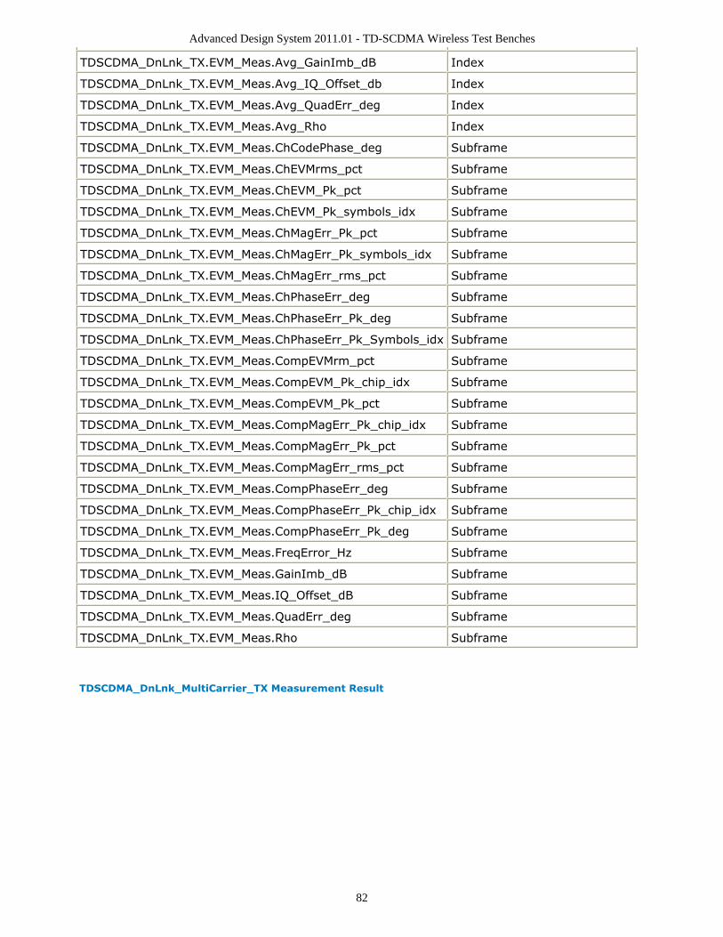
Advanced Design System 2011.01 - TD-SCDMA Wireless Test Benches
82
TDSCDMA_DnLnk_TX.EVM_Meas.Avg_GainImb_dB Index
TDSCDMA_DnLnk_TX.EVM_Meas.Avg_IQ_Offset_db Index
TDSCDMA_DnLnk_TX.EVM_Meas.Avg_QuadErr_deg Index
TDSCDMA_DnLnk_TX.EVM_Meas.Avg_Rho Index
TDSCDMA_DnLnk_TX.EVM_Meas.ChCodePhase_deg Subframe
TDSCDMA_DnLnk_TX.EVM_Meas.ChEVMrms_pct Subframe
TDSCDMA_DnLnk_TX.EVM_Meas.ChEVM_Pk_pct Subframe
TDSCDMA_DnLnk_TX.EVM_Meas.ChEVM_Pk_symbols_idx Subframe
TDSCDMA_DnLnk_TX.EVM_Meas.ChMagErr_Pk_pct Subframe
TDSCDMA_DnLnk_TX.EVM_Meas.ChMagErr_Pk_symbols_idx Subframe
TDSCDMA_DnLnk_TX.EVM_Meas.ChMagErr_rms_pct Subframe
TDSCDMA_DnLnk_TX.EVM_Meas.ChPhaseErr_deg Subframe
TDSCDMA_DnLnk_TX.EVM_Meas.ChPhaseErr_Pk_deg Subframe
TDSCDMA_DnLnk_TX.EVM_Meas.ChPhaseErr_Pk_Symbols_idx Subframe
TDSCDMA_DnLnk_TX.EVM_Meas.CompEVMrm_pct Subframe
TDSCDMA_DnLnk_TX.EVM_Meas.CompEVM_Pk_chip_idx Subframe
TDSCDMA_DnLnk_TX.EVM_Meas.CompEVM_Pk_pct Subframe
TDSCDMA_DnLnk_TX.EVM_Meas.CompMagErr_Pk_chip_idx Subframe
TDSCDMA_DnLnk_TX.EVM_Meas.CompMagErr_Pk_pct Subframe
TDSCDMA_DnLnk_TX.EVM_Meas.CompMagErr_rms_pct Subframe
TDSCDMA_DnLnk_TX.EVM_Meas.CompPhaseErr_deg Subframe
TDSCDMA_DnLnk_TX.EVM_Meas.CompPhaseErr_Pk_chip_idx Subframe
TDSCDMA_DnLnk_TX.EVM_Meas.CompPhaseErr_Pk_deg Subframe
TDSCDMA_DnLnk_TX.EVM_Meas.FreqError_Hz Subframe
TDSCDMA_DnLnk_TX.EVM_Meas.GainImb_dB Subframe
TDSCDMA_DnLnk_TX.EVM_Meas.IQ_Offset_dB Subframe
TDSCDMA_DnLnk_TX.EVM_Meas.QuadErr_deg Subframe
TDSCDMA_DnLnk_TX.EVM_Meas.Rho Subframe
TDSCDMA_DnLnk_MultiCarrier_TX Measurement Result
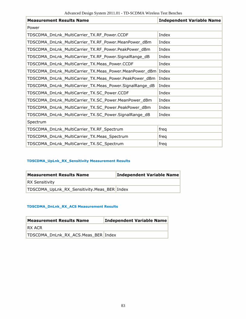
Advanced Design System 2011.01 - TD-SCDMA Wireless Test Benches
83
Measurement Results Name Independent Variable Name
Power
TDSCDMA_DnLnk_MultiCarrier_TX.RF_Power.CCDF Index
TDSCDMA_DnLnk_MultiCarrier_TX.RF_Power.MeanPower_dBm Index
TDSCDMA_DnLnk_MultiCarrier_TX.RF_Power.PeakPower_dBm Index
TDSCDMA_DnLnk_MultiCarrier_TX.RF_Power.SignalRange_dB Index
TDSCDMA_DnLnk_MultiCarrier_TX.Meas_Power.CCDF Index
TDSCDMA_DnLnk_MultiCarrier_TX.Meas_Power.MeanPower_dBm Index
TDSCDMA_DnLnk_MultiCarrier_TX.Meas_Power.PeakPower_dBm Index
TDSCDMA_DnLnk_MultiCarrier_TX.Meas_Power.SignalRange_dB Index
TDSCDMA_DnLnk_MultiCarrier_TX.SC_Power.CCDF Index
TDSCDMA_DnLnk_MultiCarrier_TX.SC_Power.MeanPower_dBm Index
TDSCDMA_DnLnk_MultiCarrier_TX.SC_Power.PeakPower_dBm Index
TDSCDMA_DnLnk_MultiCarrier_TX.SC_Power.SignalRange_dB Index
Spectrum
TDSCDMA_DnLnk_MultiCarrier_TX.RF_Spectrum freq
TDSCDMA_DnLnk_MultiCarrier_TX.Meas_Spectrum freq
TDSCDMA_DnLnk_MultiCarrier_TX.SC_Spectrum freq
TDSCDMA_UpLnk_RX_Sensitivity Measurement Results
Measurement Results Name Independent Variable Name
RX Sensitivity
TDSCDMA_UpLnk_RX_Sensitivity.Meas_BER Index
TDSCDMA_DnLnk_RX_ACS Measurement Results
Measurement Results Name Independent Variable Name
RX ACR
TDSCDMA_DnLnk_RX_ACS.Meas_BER Index
Advanced Design System 2011.01 - TD-SCDMA Wireless Test Benches
84
RF DUT Limitations for TD-SCDMAWireless Test BenchesThis section describes test bench use with typical RF DUTs, improving test benchperformance when certain RF DUT types are used, and improving simulation fidelity. Twosections regarding special attention for Spectum and EVM transmission measurements isalso included.
The RF DUT, in general, may be a circuit design with any combination and quantity ofanalog and RF components, transistors, resistors, capacitors, etc. suitable for simulationwith the Circuit Envelope simulator. More complex RF circuits will take more time tosimulate and will consume more memory.
Test bench simulation time and memory requirements can be considered to be thecombination of the requirements for the baseline test bench measurement with thesimplest RF circuit plus the requirements for a Circuit Envelope simulation for the RF DUTof interest.
An RF DUT connected to a wireless test bench can generally be used with the test benchto perform default measurements by setting the test bench Required Parameters . Defaultmeasurement parameter settings can be used (exceptions described below), for a typicalRF DUT that:
Requires an input (RF) signal with constant RF carrier frequency.The test bench RF signal source output does not produce an RF signal whose RFcarrier frequency varies with time. However, the test bench will support an output(RF) signal that contains RF carrier phase and frequency modulation as can berepresented with suitable I and Q envelope variations on a constant RF carrierfrequency.Produces an output (Meas) signal with constant RF carrier frequency.The test bench input (Meas) signal must not contain a carrier frequency whosefrequency varies with time. However, the test bench will support an input (Meas)signal that contains RF carrier phase noise or contains time varying Doppler shifts ofthe RF carrier. These signal perturbations are expected to be represented withsuitable I and Q envelope variations on a constant RF carrier frequency.Requires an input (RF) signal from a signal generator with a 50-ohm sourceresistance. Otherwise, set the SourceR parameter value in the Basic Parameters tab.Requires an input (RF) signal with no additive thermal noise (TX test benches) orsource resistor temperature set to 16.85o C (RX test benches). Otherwise, set theSourceTemp (TX and RX test benches) and EnableSourceNoise (TX test benches)parameters in the Basic Parameters tab.Requires an input (RF) signal with no spectrum mirroring. Otherwise, set theMirrorSourceSpectrum parameter value in the Basic Parameters tab.Produces an output (Meas) signal that requires a 50-ohm external load resistance.Otherwise, set the MeasR parameter value in the Basic Parameters tab.Produces an output (Meas) signal with no spectrum mirroring. Otherwise, set theMirrorMeasSpectrum parameter value in the Basic Parameters tab.
Advanced Design System 2011.01 - TD-SCDMA Wireless Test Benches
85
Relies on the test bench for any measurement-related bandpass signal filtering of theRF DUT output (Meas) signal.
When the RF DUT contains a bandpass filter with bandwidth that is on the orderof the test bench receiver system (~1 times the test bench receiver bandwidth)and the user wants a complete characterization of the RF DUT filter, the defaulttime CE_TimeStep must be set smaller.When the RF DUT bandpass filter is much wider than the test bench receiversystem (>2 times the test bench receiver bandwidth), the user may not want touse the smaller CE_TimeStep time step to fully characterize it because the userknows the RF DUT bandpass filter has little or no effect in the modulationbandwidth in this case.
Improving Test Bench Performance
This section provides information regarding improving test bench performance whencertain RF DUT types are used.
Analog/RF models (TimeDelay and all transmission line models) used with CircuitEnvelope simulation that perform linear interpolation on time domain waveforms formodeling time delay characteristics that are not an integer number of CE_TimeStepunits. Degradation is likely in some measurements, especially EVM.This limitation is due to the linear interpolation between two successive simulationtime points, which degrades waveform quality and adversely affects EVMmeasurements.To avoid this kind of simulator-induced waveform quality degradation: avoid use ofAnalog/RF models that rely on linear interpolation on time domain characteristics; or,reduce the test bench CE_TimeStep time step by a factor of 4 below the defaultCE_TimeStep (simulation time will be 4 times longer).
Analog/RF lumped components (R, L, C) used to provide bandpass filtering with abandwidth as small as the wireless signal RF information bandwidth are likely tocause degradation in some measurements, especially Spectrum. These circuit filtersrequire much smaller CE_TimeStep values than would otherwise be required for RFDUT circuits with broader bandwidths.This limitation is due to the smaller Circuit Envelope simulation time steps required toresolve the differential equations for the L, C components when narrow RFbandwidths are involved. Larger time steps degrade the resolution of the simulatedbandpass filtering effects and do not result in accurate frequency domainmeasurements, especially Spectrum and EVM measurements (when the wirelesstechnology is sensitive to frequency domain distortions).To determine that your lumped component bandwidth filter requires smallerCE_TimeStep, first characterize your filter with Harmonic Balance simulations overthe modulation bandwidth of interest centered at the carrier frequency of interest.Though it is difficult to identify an exact guideline on the Circuit Envelope time steprequired for good filter resolution, a reasonable rule is to set the CE_TimeStep to1/(double-sided 3dB bandwidth)/32.To avoid this kind of simulator-induced waveform quality degradation, avoid the useof R, L, C lumped filters with bandwidths as narrow as the RF signal information
Advanced Design System 2011.01 - TD-SCDMA Wireless Test Benches
86
bandwidth, or reduce the CE_TimeStep.
Analog/RF data-based models (such as S-parameters and noise parameters in S2Pdata files) used to provide RF bandpass filtering with a bandwidth as small as 1.5times the wireless signal RF information bandwidth are likely to cause degradation insome measurements, especially EVM.This limitation is due to causal S-parameter data about the signal carrier frequencyrequiring a sufficient number of frequency points within the modulation bandwidth;otherwise, the simulated data may cause degraded signal waveform quality. Ingeneral, there should be more than 20 frequency points in the modulationbandwidth; more is required if the filter that the S-parameter data represents hasfine-grain variations at small frequency steps.To avoid this kind of simulator-induced waveform quality degradation, avoid the useof data-based models with bandwidths as narrow as the RF signal informationbandwidth, or increase the number of frequency points in the data file within themodulation bandwidth and possibly also reduce the CE_TimeStep simulation timestep.
An additional limitation exists when noise data is included in the data file. CircuitEnvelope simulation technology does not provide frequency-dependent noise withinthe modulation bandwidth for this specific case when noise is from a frequencydomain data file. This may result in output noise power that is larger than expected;if the noise power is large enough, it may cause degraded signal waveform quality.To avoid this kind of simulator-induced waveform quality degradation avoid the useof noise data in the data-based models or use an alternate noise model.
Improving Simulation Fidelity
Some RF circuits will provide better Circuit Envelope simulation fidelity if the CE_TimeStepis reduced.
In general, the default setting of the test bench SamplesPerChip provides adequatewireless signal definition and provides the WTB_TimeStep default value.Set CE_TimeStep = 1/(1.28e6×SamplesPerChip×N)where N is an integer ≥ 1When CE_TimeStep is less than the WTB_TimeStep (i.e., N>1), the RF signal to theRF DUT is automatically upsampled from the WTB_TimeStep and the RF DUT outputsignal is automatically downsampled back to the WTB_TimeStep. This samplingintroduces a time delay to the RF DUT of 10×WTB_TimeStep and a time delay of themeasured RF DUT output signal of 20×WTB_TimeStep relative to the measured RFsignal sent to the RF DUT prior to its upsampling.
Special Attention for Spectrum Measurements
The Spectrum Measurement spectrum may have a mask against which the spectrum must
Advanced Design System 2011.01 - TD-SCDMA Wireless Test Benches
87
be lower in order to pass the wireless specification. The Spectrum measurement itself isbased on DSP algorithms that result in as much as 15 dB low-level spectrum variation atfrequencies far from the carrier.
To reduce this low-level spectrum variation, a moving average can be applied to thespectrum using the moving_average(<data>, 20) measurement expression for a 20-pointmoving average. This will give a better indication of whether the measured signal meetsthe low-level spectrum mask specification at frequencies far from the carrier.
Special Attention for EVM Measurements
For the EVM measurement, the user can specify a start time. The EVM for the initialwireless segment may be unusually high (due to signal startup transient effects or otherreasons) that cause a mis-detected first frame that the user does not want included in theRF DUT EVM measurement.
To remove the degraded initial burst EVM values from the RF DUT EVM measurement, setthe EVM_Start to a value greater than or equal to the RF DUT time delay characteristic.
Advanced Design System 2011.01 - TD-SCDMA Wireless Test Benches
88
Uplink Receiver Sensitivity Test
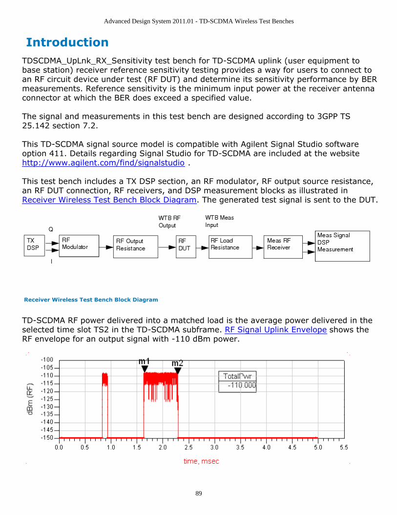
Advanced Design System 2011.01 - TD-SCDMA Wireless Test Benches
89
IntroductionTDSCDMA_UpLnk_RX_Sensitivity test bench for TD-SCDMA uplink (user equipment tobase station) receiver reference sensitivity testing provides a way for users to connect toan RF circuit device under test (RF DUT) and determine its sensitivity performance by BERmeasurements. Reference sensitivity is the minimum input power at the receiver antennaconnector at which the BER does exceed a specified value.
The signal and measurements in this test bench are designed according to 3GPP TS25.142 section 7.2.
This TD-SCDMA signal source model is compatible with Agilent Signal Studio softwareoption 411. Details regarding Signal Studio for TD-SCDMA are included at the websitehttp://www.agilent.com/find/signalstudio .
This test bench includes a TX DSP section, an RF modulator, RF output source resistance,an RF DUT connection, RF receivers, and DSP measurement blocks as illustrated inReceiver Wireless Test Bench Block Diagram. The generated test signal is sent to the DUT.
Receiver Wireless Test Bench Block Diagram
TD-SCDMA RF power delivered into a matched load is the average power delivered in theselected time slot TS2 in the TD-SCDMA subframe. RF Signal Uplink Envelope shows theRF envelope for an output signal with -110 dBm power.

Advanced Design System 2011.01 - TD-SCDMA Wireless Test Benches
90
RF Signal Uplink Envelope
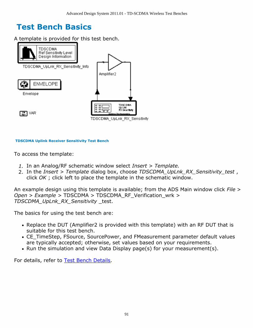
Advanced Design System 2011.01 - TD-SCDMA Wireless Test Benches
91
Test Bench BasicsA template is provided for this test bench.
TDSCDMA Uplink Receiver Sensitivity Test Bench
To access the template:
In an Analog/RF schematic window select Insert > Template.1.In the Insert > Template dialog box, choose TDSCDMA_UpLnk_RX_Sensitivity_test ,2.click OK ; click left to place the template in the schematic window.
An example design using this template is available; from the ADS Main window click File >Open > Example > TDSCDMA > TDSCDMA_RF_Verification_wrk >TDSCDMA_UpLnk_RX_Sensitivity _test.
The basics for using the test bench are:
Replace the DUT (Amplifier2 is provided with this template) with an RF DUT that issuitable for this test bench.CE_TimeStep, FSource, SourcePower, and FMeasurement parameter default valuesare typically accepted; otherwise, set values based on your requirements.Run the simulation and view Data Display page(s) for your measurement(s).
For details, refer to Test Bench Details.
Advanced Design System 2011.01 - TD-SCDMA Wireless Test Benches
92
Test Bench DetailsThe following sections provide details for setting up a test bench, setting measurementparameters for more control of the test bench, simulation measurement displays, andbaseline performance.Open and use the TDSCDMA_UpLnk_RX_Sensitivity_test template:
In an Analog/RF schematic window select Insert > Template.1.In the Insert > Template dialog box, choose TDSCDMA_UpLnk_RX_Sensitivity_test ,2.click OK ; click left to place the template in the schematic window.
Test bench setup is detailed here.
Replace the DUT (Amplifier2 is provided with this template) with an RF DUT that is1.suitable for this test bench.For information regarding using certain types of DUTs, see RF DUT Limitations forTD-SCDMA Wireless Test Benches (adswtbtds).Set the Required Parameters2.
NoteRefer to TDSCDMA_UpLnk_RX_Sensitivity (adswtbtds) for a complete list of parameters for this testbench.
Generally, default values can be accepted; otherwise, values can be changed by theuser as needed.
Set CE_TimeStep.Cosimulation occurs between the test bench (using ADS Ptolemy Data Flowsimulation technology) and the DUT (using Circuit Envelope simulationtechnology). Each technology requires its own simulation time step with time-step coordination occurring in the interface between the technologies.CE_TimeStep defines the Circuit Envelope simulation time step to be used withthis DUT. The CE_TimeStep must be set to a value equal to or a submultiple of(less than) WTB_TimeStep; otherwise, simulation will stop and an errormessage will be displayed.Note that WTB_TimeStep is not user-settable. Its value is derived from othertest bench parameter values; with default settings WTB_TimeStep= 97.65625nsec. The value is displayed in the Data Display pages as TimeStep.WTB_TimeStep = 1/(ChipRate × SamplesPerChip)whereChipRate is 1.28MHzSamplesPerChip is the number of samples per chipSet FSource, SourcePower, and FMeasurement.
FSource defines the RF frequency for the TD-SCDMA signal input to the RFDUT.SourcePower defines the power level for FSource. SourcePower is definedas the average power during the non-idle time of the TD-SCDMA signalsegment.FMeasurement defines the RF frequency output from the RF DUT to bemeasured.
Advanced Design System 2011.01 - TD-SCDMA Wireless Test Benches
93
More control of the test bench can be achieved by setting parameters on the Basic3.Parameters , Signal Parameters , and measurement categories for each activatedmeasurement. For details, refer to Setting Parameters (adswtbtds).The RF modulator (shown in the block diagram in Receiver Wireless Test Bench Block4.Diagram) uses FSource, SourcePower ( Required Parameters ),MirrorSourceSpectrum ( Basic Parameters) , GainImbalance, PhaseImbalance, IOriginOffset, Q OriginOffset, and IQ Rotation ( Signal Parameters ).The RF output resistance uses SourceR and SourceTemp ( Basic Parameters ). The RFoutput signal source has a 50-ohm (default) output resistance defined by SourceR.RF output (and input to the RF DUT) is at the frequency specified (FSource), with thespecified source resistance (SourceR) and with power (SourcePower) delivered into amatched load of resistance SourceR. The RF signal has additive Gaussian noise powerset by resistor temperature (SourceTemp).Note that the Meas_in point of the test bench provides a resistive load to the RF DUTset by the MeasR value (50-ohm default) ( Basic Parameters ).The Meas signal contains linear and nonlinear signal distortions and time delaysassociated with the RF DUT input to output characteristics.The DSP block (shown in the block diagram in Receiver Wireless Test Bench BlockDiagram) uses other Signal Parameters . More control of Circuit Envelope analysis can be achieved by setting Envelope5.controller parameters. These settings include Enable Fast Cosim, which may speedthe RF DUT simulation more than 10×. Setting these simulation options is describedin Setting Fast Cosimulation Parameters and Setting Circuit Envelope AnalysisParameters in the Wireless Test Bench Simulation documentation.After running a simulation, results will appear in a Data Display window for the6.measurement. Simulation Measurement Displays (adswtbtds) describes results foreach measurement. For general WTB Data Display details refer to Viewing WTBAnalysis Results (adswtbsim).
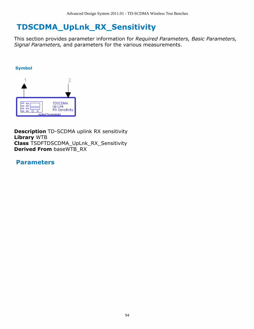
Advanced Design System 2011.01 - TD-SCDMA Wireless Test Benches
94
TDSCDMA_UpLnk_RX_Sensitivity This section provides parameter information for Required Parameters, Basic Parameters,Signal Parameters, and parameters for the various measurements.
Symbol
Description TD-SCDMA uplink RX sensitivityLibrary WTBClass TSDFTDSCDMA_UpLnk_RX_SensitivityDerived From baseWTB_RX
Parameters
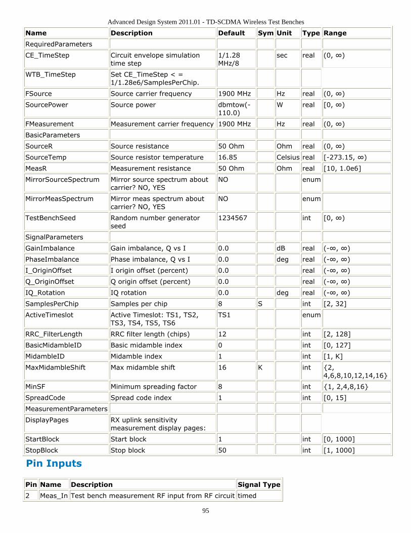
Advanced Design System 2011.01 - TD-SCDMA Wireless Test Benches
95
Name Description Default Sym Unit Type Range
RequiredParameters
CE_TimeStep Circuit envelope simulationtime step
1/1.28MHz/8
sec real (0, ∞)
WTB_TimeStep Set CE_TimeStep < =1/1.28e6/SamplesPerChip.
FSource Source carrier frequency 1900 MHz Hz real (0, ∞)
SourcePower Source power dbmtow(-110.0)
W real [0, ∞)
FMeasurement Measurement carrier frequency 1900 MHz Hz real (0, ∞)
BasicParameters
SourceR Source resistance 50 Ohm Ohm real (0, ∞)
SourceTemp Source resistor temperature 16.85 Celsius real [-273.15, ∞)
MeasR Measurement resistance 50 Ohm Ohm real [10, 1.0e6]
MirrorSourceSpectrum Mirror source spectrum aboutcarrier? NO, YES
NO enum
MirrorMeasSpectrum Mirror meas spectrum aboutcarrier? NO, YES
NO enum
TestBenchSeed Random number generatorseed
1234567 int [0, ∞)
SignalParameters
GainImbalance Gain imbalance, Q vs I 0.0 dB real (-∞, ∞)
PhaseImbalance Phase imbalance, Q vs I 0.0 deg real (-∞, ∞)
I_OriginOffset I origin offset (percent) 0.0 real (-∞, ∞)
Q_OriginOffset Q origin offset (percent) 0.0 real (-∞, ∞)
IQ_Rotation IQ rotation 0.0 deg real (-∞, ∞)
SamplesPerChip Samples per chip 8 S int [2, 32]
ActiveTimeslot Active Timeslot: TS1, TS2,TS3, TS4, TS5, TS6
TS1 enum
RRC_FilterLength RRC filter length (chips) 12 int [2, 128]
BasicMidambleID Basic midamble index 0 int [0, 127]
MidambleID Midamble index 1 int [1, K]
MaxMidambleShift Max midamble shift 16 K int {2,4,6,8,10,12,14,16}
MinSF Minimum spreading factor 8 int {1, 2,4,8,16}
SpreadCode Spread code index 1 int [0, 15]
MeasurementParameters
DisplayPages RX uplink sensitivitymeasurement display pages:
StartBlock Start block 1 int [0, 1000]
StopBlock Stop block 50 int [1, 1000]
Pin Inputs
Pin Name Description Signal Type
2 Meas_In Test bench measurement RF input from RF circuit timed
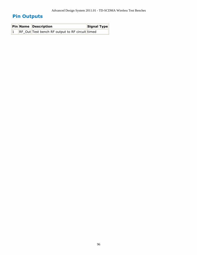
Advanced Design System 2011.01 - TD-SCDMA Wireless Test Benches
96
Pin Outputs
Pin Name Description Signal Type
1 RF_Out Test bench RF output to RF circuit timed
Advanced Design System 2011.01 - TD-SCDMA Wireless Test Benches
97
Setting ParametersMore control of the test bench can be achieved by setting parameters on the BasicParameters, Signal Parameters, and measurement categories.
NoteFor required parameter information, see Set the Required Parameters (adswtbtds).
Basic Parameters
SourceR is the RF output source resistance.1.SourceTemp is the RF output source resistance temperature (oC) and sets noise2.density in the RF output signal to (k(SourceTemp+273.15)) Watts/Hz, where k isBoltzmann's constant.MeasR defines the load resistance for the RF DUT output Meas signal into the test3.bench. This resistance loads the RF DUT output; it is also the reference resistance forMeas signal power measurements.MirrorSourceSpectrum is used to invert the polarity of the Q envelope of the4.generated RF signal before it is sent to the RF DUT. Depending on the configurationand number of mixers in an RF transmitter, the signal at the input of the DUT mayneed to be mirrored. If such an RF signal is desired, set this parameter to YES.MirrorMeasSpectrum is used to invert the polarity of the Q envelope in the Meas_in5.RF signal input to the test bench (and output from the RF DUT). Depending on theconfiguration and number of mixers in the RF DUT, the signal at its output may bemirrored compared to the signal generated by the signal source (before any mirroringis done because of the MirrorSourceSpectrum setting). Proper demodulation andmeasurement of the RF DUT output signal requires that its RF envelope is notmirrored compared to the signal generated by the signal source (before any mirroringis done because of the MirrorSourceSpectrum setting). If the Meas_in RF signal ismirrored, set this parameter to YES. Proper setting of this parameter is required formeasurements on the Meas_in signal in RX text benches and results in measurementon a signal with no spectrum mirroring.TestBenchSeed is an integer used to seed the random number generator used with6.the test bench. This value is used by all test bench random number generators,except those RF DUT components that use their own specific seed parameter.TestBenchSeed initializes the random number generation. The same seed valueproduces the same random results, thereby giving you predictable simulation results.To generate repeatable random output from simulation to simulation, use anypositive seed value. If you want the output to be truly random, enter the seed valueof 0.
Signal Parameters
GainImbalance, PhaseImbalance, I_OriginOffset, Q_OriginOffset, and IQ_Rotation are1.
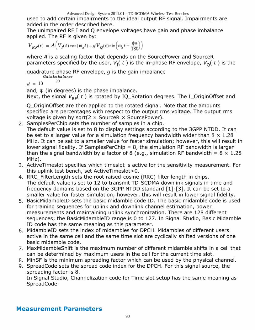
Advanced Design System 2011.01 - TD-SCDMA Wireless Test Benches
98
used to add certain impairments to the ideal output RF signal. Impairments areadded in the order described here.The unimpaired RF I and Q envelope voltages have gain and phase imbalanceapplied. The RF is given by:
where A is a scaling factor that depends on the SourcePower and SourceRparameters specified by the user, VI( t ) is the in-phase RF envelope, VQ( t ) is the
quadrature phase RF envelope, g is the gain imbalance
and, φ (in degrees) is the phase imbalance.Next, the signal VRF( t ) is rotated by IQ_Rotation degrees. The I_OriginOffset and
Q_OriginOffset are then applied to the rotated signal. Note that the amountsspecified are percentages with respect to the output rms voltage. The output rmsvoltage is given by sqrt(2 × SourceR × SourcePower).SamplesPerChip sets the number of samples in a chip.2.The default value is set to 8 to display settings according to the 3GPP NTDD. It canbe set to a larger value for a simulation frequency bandwidth wider than 8 × 1.28MHz. It can be set to a smaller value for faster simulation; however, this will result inlower signal fidelity. If SamplesPerChip = 8, the simulation RF bandwidth is largerthan the signal bandwidth by a factor of 8 (e.g., simulation RF bandwidth = 8 × 1.28MHz).ActiveTimeslot specifies which timeslot is active for the sensitivity measurement. For3.this uplink test bench, set ActiveTimeslot>0.RRC_FilterLength sets the root raised-cosine (RRC) filter length in chips.4.The default value is set to 12 to transmit TD-SCDMA downlink signals in time andfrequency domains based on the 3GPP NTDD standard [1]-[3]. It can be set to asmaller value for faster simulation; however, this will result in lower signal fidelity.BasicMidambleID sets the basic midamble code ID. The basic midamble code is used5.for training sequences for uplink and downlink channel estimation, powermeasurements and maintaining uplink synchronization. There are 128 differentsequences; the BasicMidambleID range is 0 to 127. In Signal Studio, Basic MidambleID code has the same meaning as this parameter.MidambleID sets the index of midambles for DPCH. Midambles of different users6.active in the same cell and the same time slot are cyclically shifted versions of onebasic midamble code.MaxMidambleShift is the maximum number of different midamble shifts in a cell that7.can be determined by maximum users in the cell for the current time slot.MinSF is the minimum spreading factor which can be used by the physical channel.8.SpreadCode sets the spread code index for the DPCH. For this signal source, the9.spreading factor is 8.In Signal Studio, Channelization code for Time slot setup has the same meaning asSpreadCode.
Measurement Parameters
Advanced Design System 2011.01 - TD-SCDMA Wireless Test Benches
99
This measurement requires setting the MirrorMeasSpectrum parameter such that there isan even number of spectrum mirrorings from the combined test bench source and RFDUT. For example, if MirrorSourceSpectrum = NO and the RF DUT causes its output RFsignal to have spectrum mirroring relative to its input signal, then set MirrorMeasSpectrum= YES.
DisplayPages provides Data Display page information for this test bench; it is not1.user-editable.StartBlock sets the start block. The block is the unit set of TD-SCDMA subframes for2.processing channel coding. One block contains four subframes. A value of 0 is thefirst block.StopBlock sets the stop block. For example, StopBlock=50 results in a measurement3.of 51 blocks.
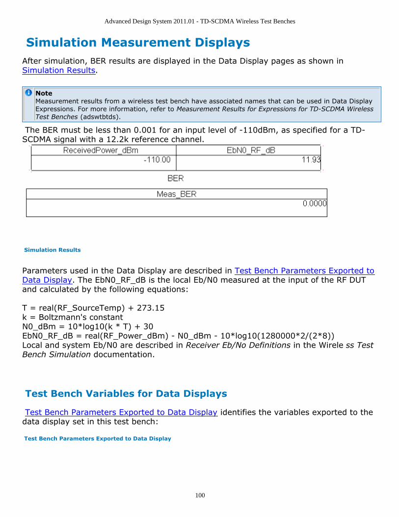
Advanced Design System 2011.01 - TD-SCDMA Wireless Test Benches
100
Simulation Measurement DisplaysAfter simulation, BER results are displayed in the Data Display pages as shown inSimulation Results.
NoteMeasurement results from a wireless test bench have associated names that can be used in Data DisplayExpressions. For more information, refer to Measurement Results for Expressions for TD-SCDMA WirelessTest Benches (adswtbtds).
The BER must be less than 0.001 for an input level of -110dBm, as specified for a TD-SCDMA signal with a 12.2k reference channel.
Simulation Results
Parameters used in the Data Display are described in Test Bench Parameters Exported toData Display. The EbN0_RF_dB is the local Eb/N0 measured at the input of the RF DUTand calculated by the following equations:
T = real(RF_SourceTemp) + 273.15k = Boltzmann's constantN0_dBm = 10*log10(k * T) + 30EbN0_RF_dB = real(RF_Power_dBm) - N0_dBm - 10*log10(1280000*2/(2*8))Local and system Eb/N0 are described in Receiver Eb/No Definitions in the Wirele ss TestBench Simulation documentation.
Test Bench Variables for Data Displays
Test Bench Parameters Exported to Data Display identifies the variables exported to thedata display set in this test bench:
Test Bench Parameters Exported to Data Display
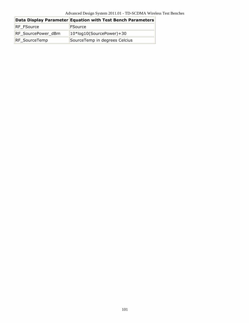
Advanced Design System 2011.01 - TD-SCDMA Wireless Test Benches
101
Data Display Parameter Equation with Test Bench Parameters
RF_FSource FSource
RF_SourcePower_dBm 10*log10(SourcePower)+30
RF_SourceTemp SourceTemp in degrees Celcius
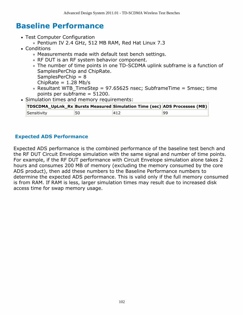
Advanced Design System 2011.01 - TD-SCDMA Wireless Test Benches
102
Baseline PerformanceTest Computer Configuration
Pentium IV 2.4 GHz, 512 MB RAM, Red Hat Linux 7.3Conditions
Measurements made with default test bench settings.RF DUT is an RF system behavior component.The number of time points in one TD-SCDMA uplink subframe is a function ofSamplesPerChip and ChipRate.SamplesPerChip = 8ChipRate = 1.28 Mb/sResultant WTB_TimeStep = 97.65625 nsec; SubframeTime = 5msec; timepoints per subframe = 51200.
Simulation times and memory requirements:TDSCDMA_UpLnk_Rx Bursts Measured Simulation Time (sec) ADS Processes (MB)
Sensitivity 50 412 99
Expected ADS Performance
Expected ADS performance is the combined performance of the baseline test bench andthe RF DUT Circuit Envelope simulation with the same signal and number of time points.For example, if the RF DUT performance with Circuit Envelope simulation alone takes 2hours and consumes 200 MB of memory (excluding the memory consumed by the coreADS product), then add these numbers to the Baseline Performance numbers todetermine the expected ADS performance. This is valid only if the full memory consumedis from RAM. If RAM is less, larger simulation times may result due to increased diskaccess time for swap memory usage.
Advanced Design System 2011.01 - TD-SCDMA Wireless Test Benches
103
References3GPP Technical Specification TS 25.142 V4.5.0 "3rd Generation Partnership Project;1.Technical Specification Group Radio Access Networks; Base station Conformance(TDD) (Release 4)," June, 2002.http://www.3gpp.org/ftp/Specs/2002-06/Rel-4/25_series/25142-450.zip ]3GPP TS 25.221, "3rd Generation Partnership Project; Technical Specification Group2.Radio Access Network; Physical channels and mapping of transport channels ontophysical channels (TDD) (Release 4)," version 4.5.0, June, 2002.http://www.3gpp.org/ftp/Specs/2002-06/Rel-4/25_series/25221-450.zip ]3GPP TS 25.223, "3rd Generation Partnership Project; Technical Specification Group3.Radio Access Network; Spreading and modulation (TDD) (Release 4)," version 4.4.0,March, 2002.http://www.3gpp.org/ftp/Specs/2002-06/Rel-4/25_series/25223-440.zip ]3GPP TS 25.102, "3rd Generation Partnership Project; Technical Specification Group4.Radio Access Networks; UE Radio Transmission and Reception (TDD) (Release 4),"version 4.5.0, June, 2002.http://www.3gpp.org/ftp/Specs/2002-06/Rel-4/25_series/25102-450.zip ]3GPP TS 34.122, "3rd Generation Partnership Project; Technical Specification Group5.Terminal; Terminal Conformance Specification; Radio Transmission and Reception(TDD) (Release 4)," version 4.4.0, June, 2002.http://www.3gpp.org/ftp/Specs/2002-06/Rel-4/34_series/34122-440.zip ]Setting up a Wireless Test Bench Analysis in the Wireless Test Bench Simulationdocumentation explains how to use test bench windows and dialogs to performanalysis tasks.Setting Circuit Envelope Analysis Parameters in the Wireless Test Bench Simulationdocumentation explains how to set up circuit envelope analysis parameters such asconvergence criteria, solver selection, and initial guess.Setting Automatic Verification Modeling Parameters in the Wireless Test BenchSimulation documentation explains how to improve simulation speed.
Advanced Design System 2011.01 - TD-SCDMA Wireless Test Benches
104
Uplink Transmitter Test
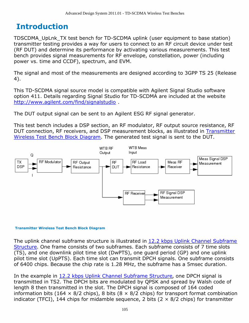
Advanced Design System 2011.01 - TD-SCDMA Wireless Test Benches
105
IntroductionTDSCDMA_UpLnk_TX test bench for TD-SCDMA uplink (user equipment to base station)transmitter testing provides a way for users to connect to an RF circuit device under test(RF DUT) and determine its performance by activating various measurements. This testbench provides signal measurements for RF envelope, constellation, power (includingpower vs. time and CCDF), spectrum, and EVM.
The signal and most of the measurements are designed according to 3GPP TS 25 (Release4).
This TD-SCDMA signal source model is compatible with Agilent Signal Studio softwareoption 411. Details regarding Signal Studio for TD-SCDMA are included at the websitehttp://www.agilent.com/find/signalstudio .
The DUT output signal can be sent to an Agilent ESG RF signal generator.
This test bench includes a DSP section, an RF modulator, RF output source resistance, RFDUT connection, RF receivers, and DSP measurement blocks, as illustrated in TransmitterWireless Test Bench Block Diagram. The generated test signal is sent to the DUT.
Transmitter Wireless Test Bench Block Diagram
The uplink channel subframe structure is illustrated in 12.2 kbps Uplink Channel SubframeStructure. One frame consists of two subframes. Each subframe consists of 7 time slots(TS), and one downlink pilot time slot (DwPTS), one guard period (GP) and one uplinkpilot time slot (UpPTS). Each time slot can transmit DPCH signals. One subframe consistsof 6400 chips. Because the chip rate is 1.28 MHz, the subframe has a 5msec duration.
In the example in 12.2 kbps Uplink Channel Subframe Structure, one DPCH signal istransmitted in TS2. The DPCH bits are modulated by QPSK and spread by Walsh code oflength 8 then transmitted in the slot. The DPCH signal is composed of 164 codedinformation bits (164 × 8/2 chips), 8 bits (8 × 8/2 chips) for transport format combinationindicator (TFCI), 144 chips for midamble sequence, 2 bits (2 × 8/2 chips) for transmitter
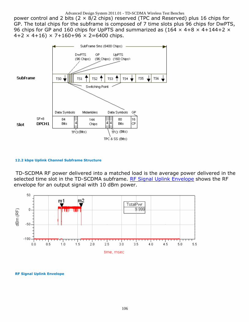
Advanced Design System 2011.01 - TD-SCDMA Wireless Test Benches
106
power control and 2 bits (2 × 8/2 chips) reserved (TPC and Reserved) plus 16 chips forGP. The total chips for the subframe is composed of 7 time slots plus 96 chips for DwPTS,96 chips for GP and 160 chips for UpPTS and summarized as (164 × 4+8 × 4+144+2 ×4+2 × 4+16) × 7+160+96 × 2=6400 chips.
12.2 kbps Uplink Channel Subframe Structure
TD-SCDMA RF power delivered into a matched load is the average power delivered in theselected time slot in the TD-SCDMA subframe. RF Signal Uplink Envelope shows the RFenvelope for an output signal with 10 dBm power.
RF Signal Uplink Envelope
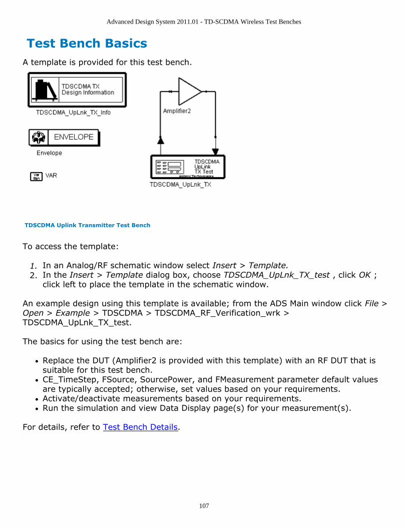
Advanced Design System 2011.01 - TD-SCDMA Wireless Test Benches
107
Test Bench BasicsA template is provided for this test bench.
TDSCDMA Uplink Transmitter Test Bench
To access the template:
In an Analog/RF schematic window select Insert > Template.1.In the Insert > Template dialog box, choose TDSCDMA_UpLnk_TX_test , click OK ;2.click left to place the template in the schematic window.
An example design using this template is available; from the ADS Main window click File >Open > Example > TDSCDMA > TDSCDMA_RF_Verification_wrk >TDSCDMA_UpLnk_TX_test.
The basics for using the test bench are:
Replace the DUT (Amplifier2 is provided with this template) with an RF DUT that issuitable for this test bench.CE_TimeStep, FSource, SourcePower, and FMeasurement parameter default valuesare typically accepted; otherwise, set values based on your requirements.Activate/deactivate measurements based on your requirements.Run the simulation and view Data Display page(s) for your measurement(s).
For details, refer to Test Bench Details.
Advanced Design System 2011.01 - TD-SCDMA Wireless Test Benches
108
Test Bench DetailsThe following sections provide details for setting up a test bench, setting measurementparameters for more control of the test bench, simulation measurement displays, andbaseline performance.Open and use the TDSCDMA_UpLnk_TX template:
In an Analog/RF schematic window select Insert > Template.1.In the Insert > Template dialog box, choose TDSCDMA_UpLnk_TX_test , click OK ;2.click left to place the template in the schematic window.
Test bench setup is detailed here.
Replace the DUT (Amplifier2 is provided with this template) with an RF DUT that is1.suitable for this test bench.For information regarding using certain types of DUTs, see RF DUT Limitations forTD-SCDMA Wireless Test Benches (adswtbtds).Set the Required Parameters2.
NoteRefer to TDSCDMA_UpLnk_TX (adswtbtds) for a complete list of parameters for this test bench.
Generally, default values can be accepted; otherwise, values can be changed by theuser as needed.
Set CE_TimeStep.Cosimulation occurs between the test bench (using ADS Ptolemy Data Flowsimulation technology) and the DUT (using Circuit Envelope simulationtechnology). Each technology requires its own simulation time step with time-step coordination occurring in the interface between the technologies.CE_TimeStep defines the Circuit Envelope simulation time step to be used withthis DUT. The CE_TimeStep must be set to a value equal to or a submultiple of(less than) WTB_TimeStep; otherwise, simulation will stop and an errormessage will be displayed.Note that WTB_TimeStep is not user-settable. Its value is derived from othertest bench parameter values; with default settings WTB_TimeStep= 97.65625nsec. The value is displayed in the Data Display pages as TimeStep.WTB_TimeStep = 1/(ChipRate × SamplesPerChip)whereChipRate is 1.28MHzSamplesPerChip is the number of samples per chipSet FSource, SourcePower, and FMeasurement.FSource defines the RF frequency for the TD-SCDMA signal input to the RF DUT.SourcePower defines the power level for FSource. SourcePower is defined as theaverage power during the non-idle time of the TD-SCDMA signal segment.FMeasurement defines the RF frequency output from the RF DUT to bemeasured.
Activate/deactivate ( YES / NO ) test bench measurements (refer to3.TDSCDMA_UpLnk_TX (adswtbtds)). At least one measurement must be enabled:
RF_EnvelopeMeasurement
Advanced Design System 2011.01 - TD-SCDMA Wireless Test Benches
109
ConstellationPowerMeasurementSpectrumMeasurementEVM_Measurement
More control of the test bench can be achieved by setting Basic Parameters , Signal4.Parameters , and parameters for each activated measurement. For details, refer toSetting Parameters (adswtbtds).The RF modulator (shown in the block diagram in Transmitter Wireless Test Bench5.Block Diagram) uses FSource, SourcePower ( Required Parameters ),MirrorSourceSpectrum ( Basic Parameters) , GainImbalance, PhaseImbalance,I_OriginOffset, Q_OriginOffset, and IQ_Rotation ( Signal Parameters ).The RF output resistance uses SourceR, SourceTemp, and EnableSourceNoise ( BasicParameters ). The RF output signal source has a 50-ohm (default) output resistancedefined by SourceR.RF output (and input to the RF DUT) is at the frequency specified (FSource), with thespecified source resistance (SourceR) and with power (SourcePower) delivered into amatched load of resistance SourceR. The RF signal has additive Gaussian noise powerset by resistor temperature (SourceTemp) (when EnableSourceNoise=YES).Note that the Meas_in point of the test bench provides a resistive load to the RF DUTset by the MeasR value (50-ohm default) ( Basic Parameters ).The Meas signal contains linear and nonlinear signal distortions and time delaysassociated with the RF DUT input to output characteristics.The TX DSP block (shown in the block diagram in Transmitter Wireless Test BenchBlock Diagram) uses other Signal Parameters . More control of Circuit Envelope analysis can be achieved by setting Envelope6.controller parameters. These settings include Enable Fast Cosim, which may speedthe RF DUT simulation more than 10×. Setting these simulation options is describedin Setting Fast Cosimulation Parameters and Setting Circuit Envelope AnalysisParameters in the Wireless Test Bench Simulation documentation. To send the RF DUT output signal to an Agilent ESG RF signal generator, set Signal7.to ESG Parameters .For details, refer to Signal to ESG Parameters (adswtbtds).After running a simulation, results will appear in a Data Display window for the8.measurement. Simulation Measurement Displays (adswtbtds) describes results foreach measurement. For general WTB Data Display details refer to Viewing WTBAnalysis Results (adswtbsim).
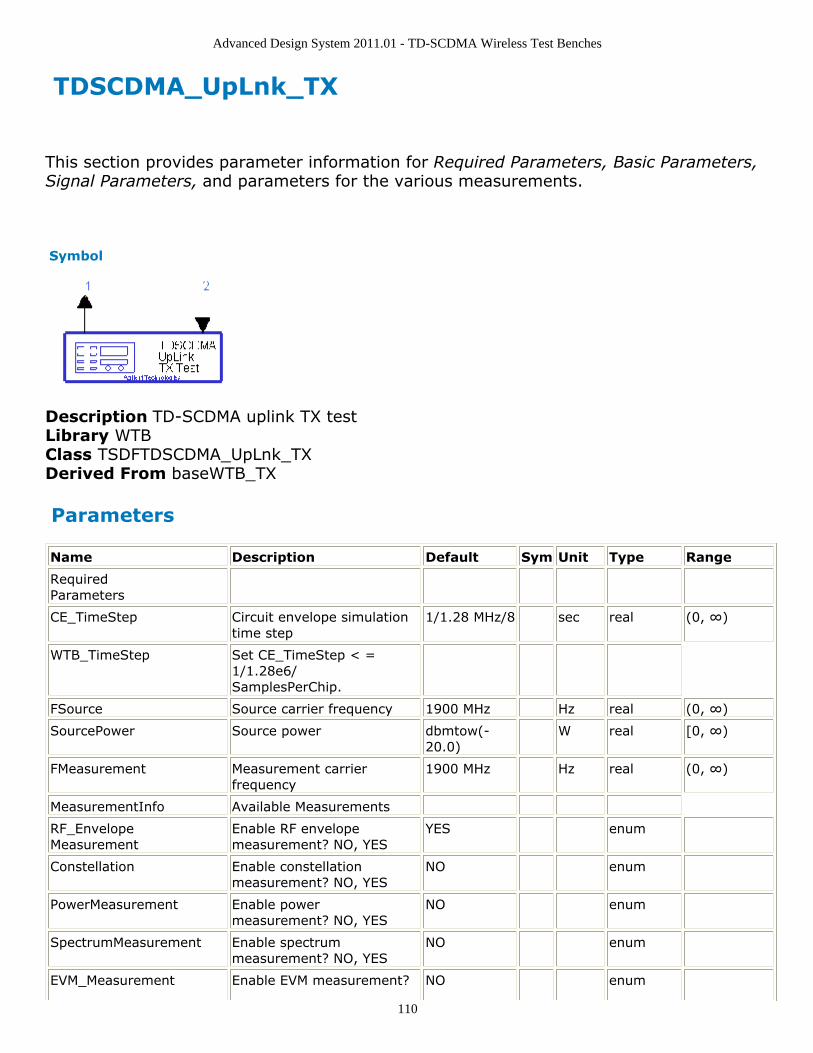
Advanced Design System 2011.01 - TD-SCDMA Wireless Test Benches
110
TDSCDMA_UpLnk_TX
This section provides parameter information for Required Parameters, Basic Parameters,Signal Parameters, and parameters for the various measurements.
Symbol
Description TD-SCDMA uplink TX testLibrary WTBClass TSDFTDSCDMA_UpLnk_TXDerived From baseWTB_TX
Parameters
Name Description Default Sym Unit Type Range
RequiredParameters
CE_TimeStep Circuit envelope simulationtime step
1/1.28 MHz/8 sec real (0, ∞)
WTB_TimeStep Set CE_TimeStep < =1/1.28e6/SamplesPerChip.
FSource Source carrier frequency 1900 MHz Hz real (0, ∞)
SourcePower Source power dbmtow(-20.0)
W real [0, ∞)
FMeasurement Measurement carrierfrequency
1900 MHz Hz real (0, ∞)
MeasurementInfo Available Measurements
RF_EnvelopeMeasurement
Enable RF envelopemeasurement? NO, YES
YES enum
Constellation Enable constellationmeasurement? NO, YES
NO enum
PowerMeasurement Enable powermeasurement? NO, YES
NO enum
SpectrumMeasurement Enable spectrummeasurement? NO, YES
NO enum
EVM_Measurement Enable EVM measurement? NO enum
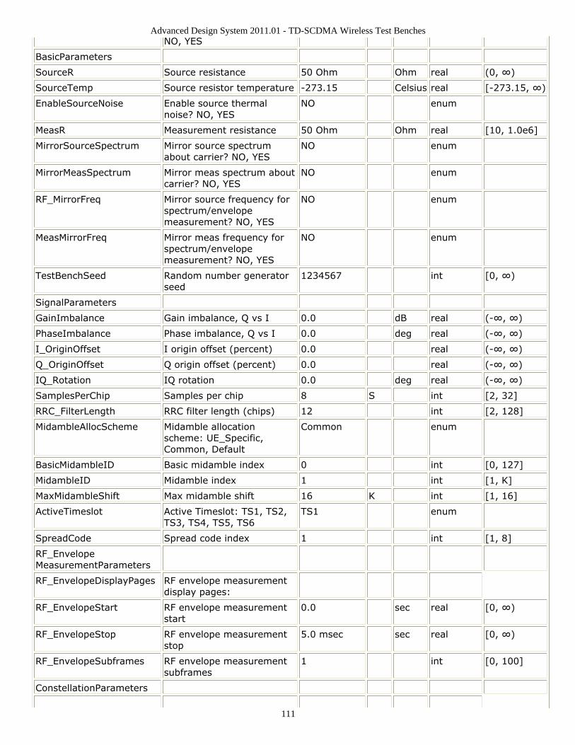
Advanced Design System 2011.01 - TD-SCDMA Wireless Test Benches
111
NO, YES
BasicParameters
SourceR Source resistance 50 Ohm Ohm real (0, ∞)
SourceTemp Source resistor temperature -273.15 Celsius real [-273.15, ∞)
EnableSourceNoise Enable source thermalnoise? NO, YES
NO enum
MeasR Measurement resistance 50 Ohm Ohm real [10, 1.0e6]
MirrorSourceSpectrum Mirror source spectrumabout carrier? NO, YES
NO enum
MirrorMeasSpectrum Mirror meas spectrum aboutcarrier? NO, YES
NO enum
RF_MirrorFreq Mirror source frequency forspectrum/envelopemeasurement? NO, YES
NO enum
MeasMirrorFreq Mirror meas frequency forspectrum/envelopemeasurement? NO, YES
NO enum
TestBenchSeed Random number generatorseed
1234567 int [0, ∞)
SignalParameters
GainImbalance Gain imbalance, Q vs I 0.0 dB real (-∞, ∞)
PhaseImbalance Phase imbalance, Q vs I 0.0 deg real (-∞, ∞)
I_OriginOffset I origin offset (percent) 0.0 real (-∞, ∞)
Q_OriginOffset Q origin offset (percent) 0.0 real (-∞, ∞)
IQ_Rotation IQ rotation 0.0 deg real (-∞, ∞)
SamplesPerChip Samples per chip 8 S int [2, 32]
RRC_FilterLength RRC filter length (chips) 12 int [2, 128]
MidambleAllocScheme Midamble allocationscheme: UE_Specific,Common, Default
Common enum
BasicMidambleID Basic midamble index 0 int [0, 127]
MidambleID Midamble index 1 int [1, K]
MaxMidambleShift Max midamble shift 16 K int [1, 16]
ActiveTimeslot Active Timeslot: TS1, TS2,TS3, TS4, TS5, TS6
TS1 enum
SpreadCode Spread code index 1 int [1, 8]
RF_EnvelopeMeasurementParameters
RF_EnvelopeDisplayPages RF envelope measurementdisplay pages:
RF_EnvelopeStart RF envelope measurementstart
0.0 sec real [0, ∞)
RF_EnvelopeStop RF envelope measurementstop
5.0 msec sec real [0, ∞)
RF_EnvelopeSubframes RF envelope measurementsubframes
1 int [0, 100]
ConstellationParameters
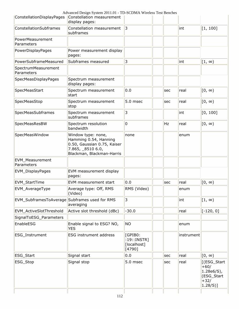
Advanced Design System 2011.01 - TD-SCDMA Wireless Test Benches
112
ConstellationDisplayPages Constellation measurementdisplay pages:
ConstellationSubframes Constellation measurementsubframes
3 int [1, 100]
PowerMeasurementParameters
PowerDisplayPages Power measurement displaypages:
PowerSubframeMeasured Subframes measured 3 int [1, ∞)
SpectrumMeasurementParameters
SpecMeasDisplayPages Spectrum measurementdisplay pages:
SpecMeasStart Spectrum measurementstart
0.0 sec real [0, ∞)
SpecMeasStop Spectrum measurementstop
5.0 msec sec real [0, ∞)
SpecMeasSubframes Spectrum measurementsubframes
3 int [0, 100]
SpecMeasResBW Spectrum resolutionbandwidth
0 Hz real [0, ∞)
SpecMeasWindow Window type: none,Hamming 0.54, Hanning0.50, Gaussian 0.75, Kaiser7.865, _8510 6.0,Blackman, Blackman-Harris
none enum
EVM_MeasurementParameters
EVM_DisplayPages EVM measurement displaypages:
EVM_StartTime EVM measurement start 0.0 sec real [0, ∞)
EVM_AverageType Average type: Off, RMS(Video)
RMS (Video) enum
EVM_SubframesToAverage Subframes used for RMSaveraging
3 int [1, ∞)
EVM_ActiveSlotThreshold Active slot threshold (dBc) -30.0 real [-120, 0]
SignalToESG_Parameters
EnableESG Enable signal to ESG? NO,YES
NO enum
ESG_Instrument ESG instrument address [GPIB0::19::INSTR][localhost][4790]
instrument
ESG_Start Signal start 0.0 sec real [0, ∞)
ESG_Stop Signal stop 5.0 msec sec real [(ESG_Start+60/1.28e6/S),(ESG_Start+32/1.28/S)]
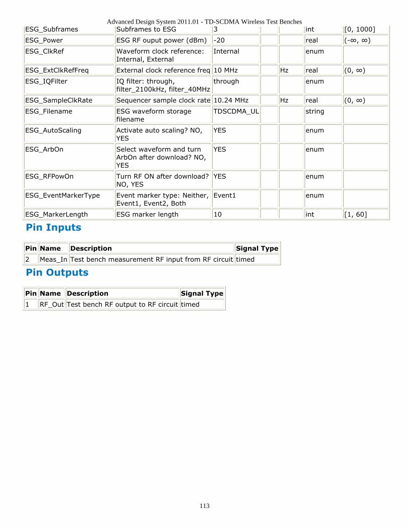
Advanced Design System 2011.01 - TD-SCDMA Wireless Test Benches
113
ESG_Subframes Subframes to ESG 3 int [0, 1000]
ESG_Power ESG RF ouput power (dBm) -20 real (-∞, ∞)
ESG_ClkRef Waveform clock reference:Internal, External
Internal enum
ESG_ExtClkRefFreq External clock reference freq 10 MHz Hz real (0, ∞)
ESG_IQFilter IQ filter: through,filter_2100kHz, filter_40MHz
through enum
ESG_SampleClkRate Sequencer sample clock rate 10.24 MHz Hz real (0, ∞)
ESG_Filename ESG waveform storagefilename
TDSCDMA_UL string
ESG_AutoScaling Activate auto scaling? NO,YES
YES enum
ESG_ArbOn Select waveform and turnArbOn after download? NO,YES
YES enum
ESG_RFPowOn Turn RF ON after download?NO, YES
YES enum
ESG_EventMarkerType Event marker type: Neither,Event1, Event2, Both
Event1 enum
ESG_MarkerLength ESG marker length 10 int [1, 60]
Pin Inputs
Pin Name Description Signal Type
2 Meas_In Test bench measurement RF input from RF circuit timed
Pin Outputs
Pin Name Description Signal Type
1 RF_Out Test bench RF output to RF circuit timed

Advanced Design System 2011.01 - TD-SCDMA Wireless Test Benches
114
Setting ParametersMore control of the test bench can be achieved by setting parameters in the BasicParameters , Signal Parameters , and measurement categories for the activatedmeasurements.
NoteFor required parameter information, see Set the Required Parameters (adswtbtds).
Basic Parameters
SourceR is the RF output source resistance.1.SourceTemp is the RF output source resistance temperature (oC) and sets noise2.density in the RF output signal to (k(SourceTemp+273.15)) Watts/Hz, where k isBoltzmann's constant.EnableSourceNoise, when set to NO disables the SourceTemp and effectively sets it3.to -273.15oC (0 Kelvin). When set to YES, the noise density due to SourceTemp isenabled.MeasR defines the load resistance for the RF DUT output Meas signal into the test4.bench. This resistance loads the RF DUT output; it is also the reference resistance forMeas signal power measurements.MirrorSourceSpectrum is used to invert the polarity of the Q envelope of the5.generated RF signal before it is sent to the RF DUT. Depending on the configurationand number of mixers in an RF transmitter, the signal at the input of the DUT mayneed to be mirrored. If such an RF signal is desired, set this parameter to YES.MirrorMeasSpectrum is used to invert the polarity of the Q envelope in the Meas_in6.RF signal input to the test bench (and output from the RF DUT). Depending on theconfiguration and number of mixers in the RF DUT, the signal at its output may bemirrored compared to the signal generated by the signal source (before any mirroringis done because of the MirrorSourceSpectrum setting). Proper demodulation andmeasurement of the RF DUT output signal requires that its RF envelope is notmirrored compared to the signal generated by the signal source (before any mirroringis done because of the MirrorSourceSpectrum setting). If the Meas_in RF signal ismirrored, set this parameter to YES. Proper setting of this parameter is required formeasurements on the Meas_in signal in TX test benches (EVM, Constellation, CDP,PCDE) and results in measurement on a signal with no spectrum mirroring.TestBenchSeed is an integer used to seed the random number generator used with7.the test bench. This value is used by all test bench random number generators,except those RF DUT components that use their own specific seed parameter.TestBenchSeed initializes the random number generation. The same seed valueproduces the same random results, thereby giving you predictable simulation results.To generate repeatable random output from simulation to simulation, use anypositive seed value. If you want the output to be truly random, enter the seed valueof 0.RF_MirrorFreq is used to invert the polarity of the Q envelope in the RF_out RF signal8.for RF envelope, ppectrum, ACLR, and occupied bandwidth measurements.

Advanced Design System 2011.01 - TD-SCDMA Wireless Test Benches
115
RF_MirrorFreq is typically set by the user to NO when MirrorSourceSpectrum = NO;RF_MirrorFreq is typically set by the user to YES when MirrorSourceSpectrum = YES.Both settings result in viewing the RF_out signal with no spectrum mirroring. Othersettings by the user result in RF_out signal for RF_Envelope and Spectrummeasurements with spectrum mirroring.MeasMirrorFreq is used to invert the polarity of the Q envelope in the Meas_in RF9.signal for the RF envelope, spectrum, ACLR, and occupied bandwidth measurements.MeasMirrorFreq is typically set to NO by the user when the combination of theMirrorSourceSpectrum value and any signal mirroring in the users RF DUT results inno spectrum mirroring in the Meas_in signal. MeasMirrorFreq is typically set to YESby the user when the combination of the MirrorSourceSpectrum and RF DUT resultsin spectrum mirroring in the Meas_in signal.Other settings result in Meas_in signal for RF_Envelope and Spectrum measurementswith spectrum mirroring. The MirrorMeasSpectrum parameter setting has no impacton the setting or use of the MeasMirrorFreq parameter.
Signal Parameters
GainImbalance, PhaseImbalance, I_OriginOffset, Q_OriginOffset, and IQ_Rotation are1.used to add certain impairments to the ideal output RF signal. Impairments areadded in the order described here.The unimpaired RF I and Q envelope voltages have gain and phase imbalanceapplied. The RF is given by:
where A is a scaling factor that depends on the SourcePower and SourceRparameters specified by the user, VI( t ) is the in-phase RF envelope, VQ( t ) is the
quadrature phase RF envelope, g is the gain imbalance
and, φ (in degrees) is the phase imbalance.Next, the signal VRF( t ) is rotated by IQ_Rotation degrees. The I_OriginOffset and
Q_OriginOffset are then applied to the rotated signal. Note that the amountsspecified are percentages with respect to the output rms voltage. The output rmsvoltage is given by sqrt(2 × SourceR × SourcePower).SamplesPerChip sets the number of samples in a chip.2.The default value is set to 8 to display settings according to the 3GPP NTDD. It canbe set to a larger value for a simulation frequency bandwidth wider than 8 × 1.28MHz. It can be set to a smaller value for faster simulation; however, this will result inlower signal fidelity. If SamplesPerChip = 8, the simulation RF bandwidth is largerthan the signal bandwidth by a factor of 8 (e.g., simulation RF bandwidth = 8 × 1.28MHz).RRC_FilterLength sets root raised-cosine (RRC) filter length in chips.3.The default value is set to 12 to transmit TD-SCDMA downlink signals in time andfrequency domains based on the 3GPP NTDD standard. It can be set to a smallervalue for faster simulation; however, this will result in lower signal fidelity.
Advanced Design System 2011.01 - TD-SCDMA Wireless Test Benches
116
MidambleAllocScheme is used to select the midamble allocation scheme. There are4.three midamble allocation schemes based on the 3GPP NTDD standard [1], [2]. Toset the MidambleAllocScheme parameter based on the 3GPP NTDD standard [1],related parameters must be set as stated here.
UE specific midamble allocation : a UE specific midamble for uplink anddownlink is explicitly assigned by higher layers.if MidambleAllocScheme=UE_Specific, BasicMidambleID, MaxMidambleShift, andMidambleID are used to specify which midamble is exported.Common midamble allocation : the midamble for downlink is allocated bylayer 1 depending on the number of channelization codes currently present inthe downlink time slot.if MidambleAllocScheme=Common, only BasicMidambleID andMaxMidambleShift are used to specify which midamble is exported; theMidambleID parameter is ignored.Default midamble allocation : the midamble for uplink and downlink isassigned by layer 1 depending on the associated channelization code.if MidambleAllocScheme=Default, only BasicMidambleID and MaxMidambleShiftare used to specify which midamble is exported; the MidambleID parameter isignored.
BasicMidambleID sets the basic midamble code ID. The basic midamble code is used5.for training sequences for uplink and downlink channel estimation, powermeasurements and maintaining uplink synchronization. There are 128 differentsequences; the BasicMidambleID range is 0 to 127. In Signal Studio, Basic MidambleID code has the same meaning as this parameter.MidambleID sets the index of midambles for DPCH. Midambles of different users6.active in the same cell and the same time slot are cyclically shifted versions of onebasic midamble code.Let P = 128, the length of basic midamble and K=MaxMidambleShift, then
W = , is the shift between midambles and denotes the largest number less than or equal to x. MidambleID range is from 1 toMaxMidambleShift.MidambleID and MaxMidambleShift together correspond to the Midamble Offsetparameter in Signal Studio for Timeslot setup. Midamble Offset = MidambleID × W.MaxMidambleShift is the maximum number of different midamble shifts in a cell that7.can be determined by maximum users in the cell for the current time slot.ActiveTimeSlot specifies which slot signal in the subframe will be transmitted.8.Referring to 12.2 kbps Uplink Channel Subframe Structure (adswtbtds), whenActiveTimeSlot=2, TS2 is used.SpreadCode sets the spread code index for the DPCH. For this test bench, the9.spreading factor is 8.In Signal Studio, Channelization code for Time slot setup has the same meaning asSpreadCode.
RF Envelope Measurement Parameters
The RF Envelope measurement is not affected by the MirrorMeasSpectrum parameter. To
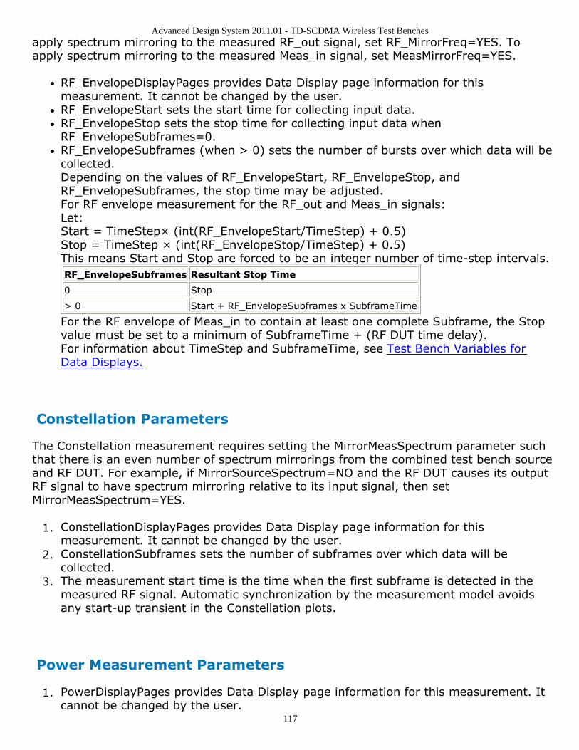
Advanced Design System 2011.01 - TD-SCDMA Wireless Test Benches
117
apply spectrum mirroring to the measured RF_out signal, set RF_MirrorFreq=YES. Toapply spectrum mirroring to the measured Meas_in signal, set MeasMirrorFreq=YES.
RF_EnvelopeDisplayPages provides Data Display page information for thismeasurement. It cannot be changed by the user.RF_EnvelopeStart sets the start time for collecting input data.RF_EnvelopeStop sets the stop time for collecting input data whenRF_EnvelopeSubframes=0.RF_EnvelopeSubframes (when > 0) sets the number of bursts over which data will becollected.Depending on the values of RF_EnvelopeStart, RF_EnvelopeStop, andRF_EnvelopeSubframes, the stop time may be adjusted.For RF envelope measurement for the RF_out and Meas_in signals:Let:Start = TimeStep× (int(RF_EnvelopeStart/TimeStep) + 0.5)Stop = TimeStep × (int(RF_EnvelopeStop/TimeStep) + 0.5)This means Start and Stop are forced to be an integer number of time-step intervals.RF_EnvelopeSubframes Resultant Stop Time
0 Stop
> 0 Start + RF_EnvelopeSubframes x SubframeTime
For the RF envelope of Meas_in to contain at least one complete Subframe, the Stopvalue must be set to a minimum of SubframeTime + (RF DUT time delay).For information about TimeStep and SubframeTime, see Test Bench Variables forData Displays.
Constellation Parameters
The Constellation measurement requires setting the MirrorMeasSpectrum parameter suchthat there is an even number of spectrum mirrorings from the combined test bench sourceand RF DUT. For example, if MirrorSourceSpectrum=NO and the RF DUT causes its outputRF signal to have spectrum mirroring relative to its input signal, then setMirrorMeasSpectrum=YES.
ConstellationDisplayPages provides Data Display page information for this1.measurement. It cannot be changed by the user.ConstellationSubframes sets the number of subframes over which data will be2.collected.The measurement start time is the time when the first subframe is detected in the3.measured RF signal. Automatic synchronization by the measurement model avoidsany start-up transient in the Constellation plots.
Power Measurement Parameters
PowerDisplayPages provides Data Display page information for this measurement. It1.cannot be changed by the user.
Advanced Design System 2011.01 - TD-SCDMA Wireless Test Benches
118
PowerSubframeMeasured sets the number of subframes over which data will be2.collected.The measurement start time is the time when the first subframe is detected in the3.measured RF signal. Automatic synchronization by the measurement model avoidsany start-up transient in the Constellation plots. The measurement stop time is thisstart time plus PowerSubframeMeasured × SubframeTime. SubframeTime isdescribed in Test Bench Variables for Data Displays.
Spectrum Measurement Parameters
The Spectrum measurement calculates the spectrum of the input signal. Averaging thespectrum over multiple subframes can be enabled as described in this section.
This measurement is not affected by the MirrorMeasSpectrum parameter. To applyspectrum mirroring to the measured RF_out signal, set RF_MirrorFreq = YES; to applyspectrum mirroring to the measured Meas_in signal, set MeasMirrorFreq = YES.
In the following, TimeStep denotes the simulation time step and FMeasurement denotesthe measured RF signal characterization frequency.
The measurement outputs the complex amplitude voltage values at the frequencies1.of the spectral tones. It does not output the power at the frequencies of the spectraltones. However, one can calculate and display the power spectrum as well as themagnitude and phase spectrum by using the dBm, mag, and phase functions of thedata display window.Note that the dBm function assumes a 50-ohm reference resistance; if a differentmeasurement was used in the test bench, its value can be specified as a secondargument to the dBm function, for example, dBm(SpecMeas, Meas_RefR) whereSpecMeas is the instance name of the spectrum measurement and Meas_RefR is theresistive load used.By default, the displayed spectrum extends from FMeasurement - 1/(2×TimeStep) Hzto FMeasurement + 1/(2×TimeStep) Hz. When FMeasurement < 1/(2×TimeStep),the default spectrum extends to negative frequencies. The spectral content at thesenegative frequencies is conjugated, mirrored, and added to the spectral content ofthe closest positive frequency. The negative frequency tones are then displayed onthe positive frequency axis as would happen in an RF spectrum analyzermeasurement instrument. This process may introduce an error in the displayedfrequency for the mirrored tones. The absolute error introduced is less than(spectrum frequency step) / 2 (see Effect of Values for SpecMeasStart,SpecMeasStop, SpecMeasSubframes, and SpecMeasResBW for the definition ofspectrum frequency step).The basis of the algorithm used by the spectrum measurement is the chirp-Ztransform. The algorithm can use multiple subframes and average the results toachieve video averaging (see note 6).SpecMeasDisplayPages provides information regarding Data Display pages for this2.measurement. It cannot be changed by the user.SpecMeasStart sets the start time for collecting input data.3.
Advanced Design System 2011.01 - TD-SCDMA Wireless Test Benches
119
SpecMeasStop sets the stop time for collecting input data when SpecMeasSubframes4.= 0 and SpecMeasResBW = 0.SpecMeasSubframes sets the number of segments over which data will be collected.5.SpecMeasResBW sets the resolution bandwidth of the spectrum.6.Depending on the values of SpecMeasStart, SpecMeasStop, SpecMeasSubframes, andSpecMeasResBW, the stop time may be adjusted or spectrum video averaging mayoccur (or both). The different cases are described in Effect of Values forSpecMeasStart, SpecMeasStop, SpecMeasSubframes, and SpecMeasResBW.Referring to Effect of Values for SpecMeasStart, SpecMeasStop, SpecMeasSubframes,and SpecMeasResBW, letStart = TimeStep × int((SpecMeasStart/TimeStep) + 0.5)Stop = TimeStep × int((SpecMeasStop/TimeStep) + 0.5)(This means Start and Stop are forced to be an integer number of time stepintervals.)X = normalized equivalent noise bandwidth of the windowStart and Stop times are used for RF_out and Meas_in signal spectrum analyses. TheMeas_in signal is delayed in time from the RF_out signal by the value of the RF DUTtime delay. Therefore, for RF DUT time delay >0, the RF_out and Meas_in signals areinherently different and spectrum display differences can be expected.TimeStep and SubframeTime are defined in the Test Bench Variables for DataDisplays section.Equivalent noise bandwidth (ENBW) compares the window to an ideal, rectangularfilter. It is the equivalent width of a rectangular filter that passes the same amount ofwhite noise as the window. Normalized ENBW (NENBW) is ENBW multiplied by theduration of the signal being windowed. (Refer to note 7 regarding the various windowoptions and Window Options and Normalized Equivalent Noise Bandwidth regardingNENBW for the various windows.)
Effect of Values for SpecMeasStart, SpecMeasStop, SpecMeasSubframes, and SpecMeasResBW
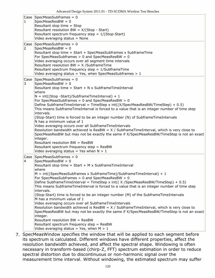
Advanced Design System 2011.01 - TD-SCDMA Wireless Test Benches
120
Case1
SpecMeasSubframes = 0SpecMeasResBW = 0Resultant stop time = StopResultant resolution BW = X/(Stop - Start)Resultant spectrum frequency step = 1/(Stop-Start)Video averaging status = None
Case2
SpecMeasSubframes > 0SpecMeasResBW = 0Resultant stop time = Start + SpecMeasSubframes x SubframeTimeFor SpecMeasSubframes > 0 and SpecMeasResBW = 0Video averaging occurs over all segment time intervalsResultant resolution BW = X /SubframeTimeResultant spectrum frequency step = 1/SubframeTimeVideo averaging status = Yes, when SpecMeasSubframes > 1
Case3
SpecMeasSubframes = 0SpecMeasResBW > 0Resultant stop time = Start + N x SubframeTimeIntervalwhereN = int((Stop -Start)/SubframeTimeInterval) + 1For SpecMeasSubframes = 0 and SpecMeasResBW > 0Define SubframeTimeInterval = TimeStep x int((X/SpecMeasResBW/TimeStep) + 0.5)This means SubframeTimeInterval is forced to a value that is an integer number of time stepintervals.(Stop-Start) time is forced to be an integer number (N) of SubframeTimeIntervalsN has a minimum value of 1Video averaging occurs over all SubframeTimeIntervalsResolution bandwidth achieved is ResBW = X / SubframeTimeInterval, which is very close toSpecMeasResBW but may not be exactly the same if X/SpecMeasResBW/TimeStep is not an exactinteger.Resultant resolution BW = ResBWResultant spectrum frequency step = ResBWVideo averaging status = Yes when N > 1
Case4
SpecMeasSubframes > 0SpecMeasResBW > 0Resultant stop time = Start + M x SubframeTimeIntervalwhereM = int((SpecMeasSubframes x SubframeTime)/SubframeTimeInterval) + 1For SpecMeasSubframes > 0 and SpecMeasResBW > 0Define SubframeTimeInterval = TimeStep x int(( X /SpecMeasResBW/TimeStep) + 0.5)This means SubframeTimeInterval is forced to a value that is an integer number of time stepintervals.(Stop-Start) time is forced to be an integer number (M) of the SubframeTimeIntervalsM has a minimum value of 1Video averaging occurs over all SubframeTimeIntervalsResolution bandwidth achieved is ResBW = X / SubframeTimeInterval, which is very close toSpecMeasResBW but may not be exactly the same if X/SpecMeasResBW/TimeStep is not an exactinteger.Resultant resolution BW = ResBWResultant spectrum frequency step = ResBWVideo averaging status = Yes, when M > 1
SpecMeasWindow specifies the window that will be applied to each segment before7.its spectrum is calculated. Different windows have different properties, affect theresolution bandwidth achieved, and affect the spectral shape. Windowing is oftennecessary in transform-based (chirp-Z, FFT) spectrum estimation in order to reducespectral distortion due to discontinuous or non-harmonic signal over themeasurement time interval. Without windowing, the estimated spectrum may suffer
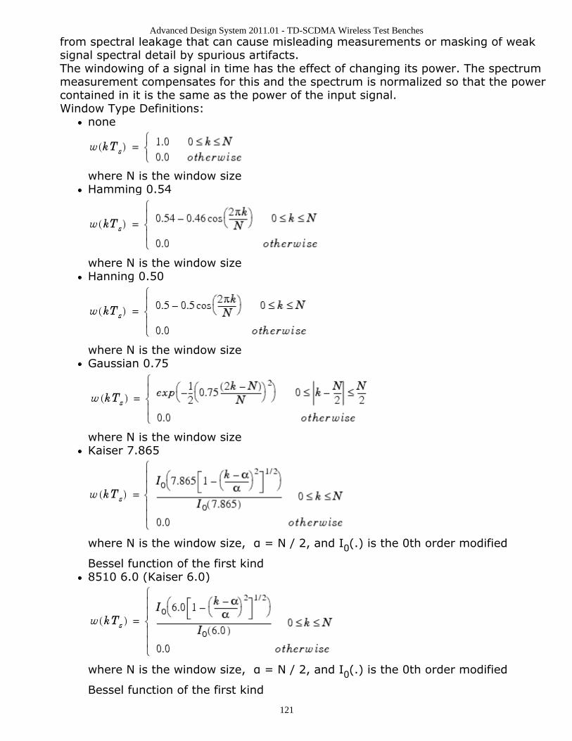
Advanced Design System 2011.01 - TD-SCDMA Wireless Test Benches
121
from spectral leakage that can cause misleading measurements or masking of weaksignal spectral detail by spurious artifacts.The windowing of a signal in time has the effect of changing its power. The spectrummeasurement compensates for this and the spectrum is normalized so that the powercontained in it is the same as the power of the input signal.Window Type Definitions:
none
where N is the window sizeHamming 0.54
where N is the window sizeHanning 0.50
where N is the window sizeGaussian 0.75
where N is the window sizeKaiser 7.865
where N is the window size, α = N / 2, and I0(.) is the 0th order modified
Bessel function of the first kind8510 6.0 (Kaiser 6.0)
where N is the window size, α = N / 2, and I0(.) is the 0th order modified
Bessel function of the first kind
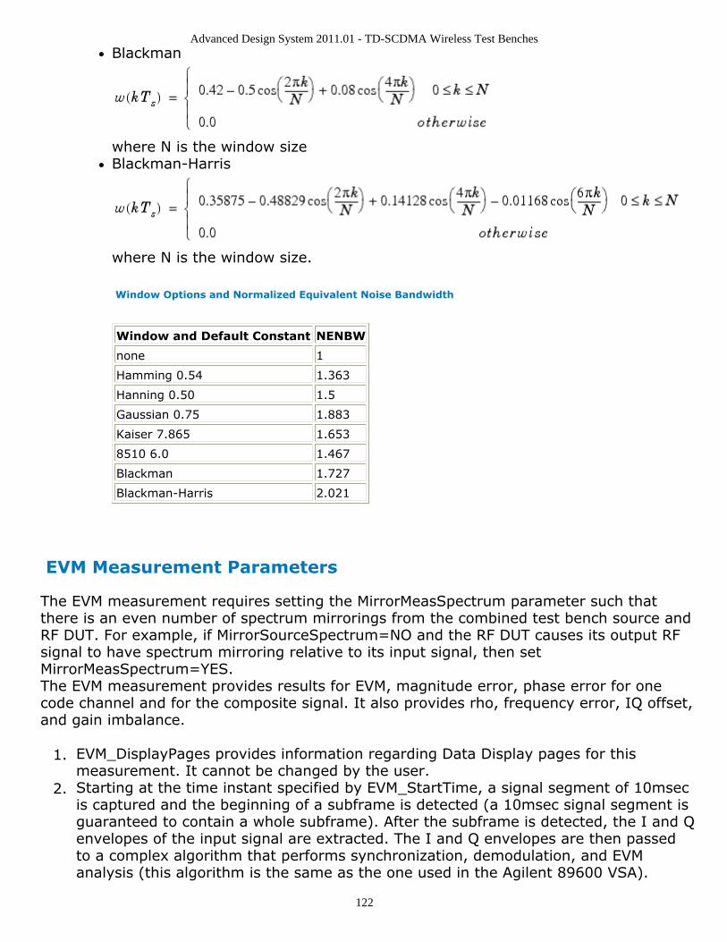
Advanced Design System 2011.01 - TD-SCDMA Wireless Test Benches
122
Blackman
where N is the window sizeBlackman-Harris
where N is the window size.
Window Options and Normalized Equivalent Noise Bandwidth
Window and Default Constant NENBW
none 1
Hamming 0.54 1.363
Hanning 0.50 1.5
Gaussian 0.75 1.883
Kaiser 7.865 1.653
8510 6.0 1.467
Blackman 1.727
Blackman-Harris 2.021
EVM Measurement Parameters
The EVM measurement requires setting the MirrorMeasSpectrum parameter such thatthere is an even number of spectrum mirrorings from the combined test bench source andRF DUT. For example, if MirrorSourceSpectrum=NO and the RF DUT causes its output RFsignal to have spectrum mirroring relative to its input signal, then setMirrorMeasSpectrum=YES.The EVM measurement provides results for EVM, magnitude error, phase error for onecode channel and for the composite signal. It also provides rho, frequency error, IQ offset,and gain imbalance.
EVM_DisplayPages provides information regarding Data Display pages for this1.measurement. It cannot be changed by the user.Starting at the time instant specified by EVM_StartTime, a signal segment of 10msec2.is captured and the beginning of a subframe is detected (a 10msec signal segment isguaranteed to contain a whole subframe). After the subframe is detected, the I and Qenvelopes of the input signal are extracted. The I and Q envelopes are then passedto a complex algorithm that performs synchronization, demodulation, and EVManalysis (this algorithm is the same as the one used in the Agilent 89600 VSA).
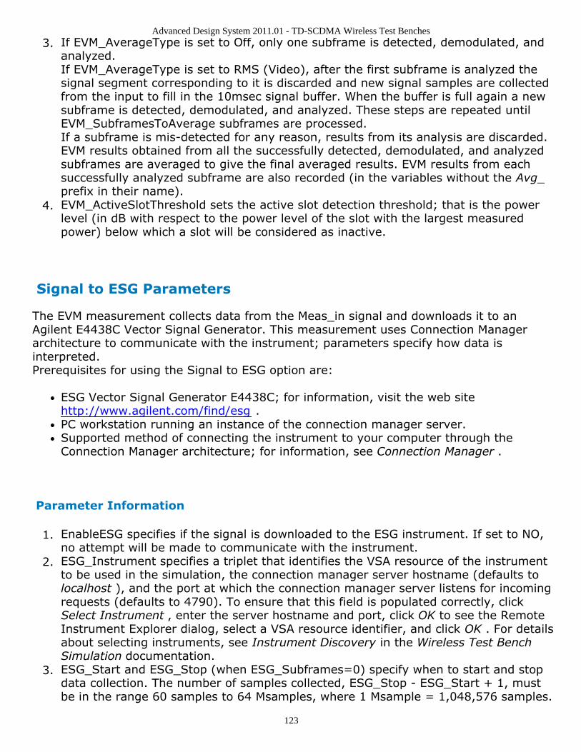
Advanced Design System 2011.01 - TD-SCDMA Wireless Test Benches
123
If EVM_AverageType is set to Off, only one subframe is detected, demodulated, and3.analyzed.If EVM_AverageType is set to RMS (Video), after the first subframe is analyzed thesignal segment corresponding to it is discarded and new signal samples are collectedfrom the input to fill in the 10msec signal buffer. When the buffer is full again a newsubframe is detected, demodulated, and analyzed. These steps are repeated untilEVM_SubframesToAverage subframes are processed.If a subframe is mis-detected for any reason, results from its analysis are discarded.EVM results obtained from all the successfully detected, demodulated, and analyzedsubframes are averaged to give the final averaged results. EVM results from eachsuccessfully analyzed subframe are also recorded (in the variables without the Avg_prefix in their name).EVM_ActiveSlotThreshold sets the active slot detection threshold; that is the power4.level (in dB with respect to the power level of the slot with the largest measuredpower) below which a slot will be considered as inactive.
Signal to ESG Parameters
The EVM measurement collects data from the Meas_in signal and downloads it to anAgilent E4438C Vector Signal Generator. This measurement uses Connection Managerarchitecture to communicate with the instrument; parameters specify how data isinterpreted.Prerequisites for using the Signal to ESG option are:
ESG Vector Signal Generator E4438C; for information, visit the web sitehttp://www.agilent.com/find/esg .PC workstation running an instance of the connection manager server.Supported method of connecting the instrument to your computer through theConnection Manager architecture; for information, see Connection Manager .
Parameter Information
EnableESG specifies if the signal is downloaded to the ESG instrument. If set to NO,1.no attempt will be made to communicate with the instrument.ESG_Instrument specifies a triplet that identifies the VSA resource of the instrument2.to be used in the simulation, the connection manager server hostname (defaults tolocalhost ), and the port at which the connection manager server listens for incomingrequests (defaults to 4790). To ensure that this field is populated correctly, clickSelect Instrument , enter the server hostname and port, click OK to see the RemoteInstrument Explorer dialog, select a VSA resource identifier, and click OK . For detailsabout selecting instruments, see Instrument Discovery in the Wireless Test BenchSimulation documentation.ESG_Start and ESG_Stop (when ESG_Subframes=0) specify when to start and stop3.data collection. The number of samples collected, ESG_Stop - ESG_Start + 1, mustbe in the range 60 samples to 64 Msamples, where 1 Msample = 1,048,576 samples.
Advanced Design System 2011.01 - TD-SCDMA Wireless Test Benches
124
The ESG requires an even number of samples; the last sample will be discarded ifESG_Stop - ESG_Start + 1 is odd.ESG_Subframes sets the number of subframes over which data will be collected. If4.ESG_Subframes is greater than zero, then ESG_Stop is forced to ESG_Start +ESG_Subframes x SubframeTime where SubframeTime is 5 msec.ESG_ClkRef specifies an internal or external reference for the ESG clock generator. If5.set to External, the ESG_ExtClkRefFreq parameter sets the frequency of this clock.ESG_IQFilter specifies the cutoff frequency for the reconstruction filter that lies6.between the DAC output and the Dual Arbitrary Waveform Generator output insidethe ESG.ESG_SampleClkRate sets the sample clock rate for the DAC output.7.ESG_Filename sets the name of the waveform inside the ESG that will hold the8.downloaded data.The ESG driver expects data in the range {-1, 1}. The ESG_AutoScaling parameter9.specifies whether to scale inputs to fit this range. If set to YES, inputs are scaled tothe range {-1, 1}; if set to NO, raw simulation data is downloaded to the ESGwithout any scaling, but data outside the range {-1, 1} is clipped to -1 or 1. If set toYES, scaling is also applied to data written to the local file (ESG_Filename setting).If ESG_ArbOn is set to YES, the ESG will start generating the signal immediately after10.simulation data is downloaded; if set to NO, waveform generation must be turned onat the ESG front panel.If ESG_RFPowOn is set to YES, the ESG will turn RF power on immediately after11.simulation data is downloaded. If ESG_RFPowOn is set to NO (default), RF powermust be turned on at the ESG front panel.ESG_EventMarkerType specifies which ESG Event markers are enabled: Event1,12.Event2, Both, or Neither. Event markers are used for synchronizing other instrumentsto the ESG. When event markers are enabled, Event1 or Event2 (or both) is setbeginning from the first sample of the downloaded Arb waveform over the range ofpoints specified by the ESG_MarkerLength parameter. This is equivalent to settingthe corresponding event from the front panel of the ESG.ESG_MarkerLength specifies the range of points over which the markers must be set13.starting from the first point of the waveform. Depending on theESG_EventMarkerType setting, the trigger length of Event1 or Event2 (or both) is setto a multiple of the pulsewidth that, in turn, is determined by the sample clock rateof the DAC output.
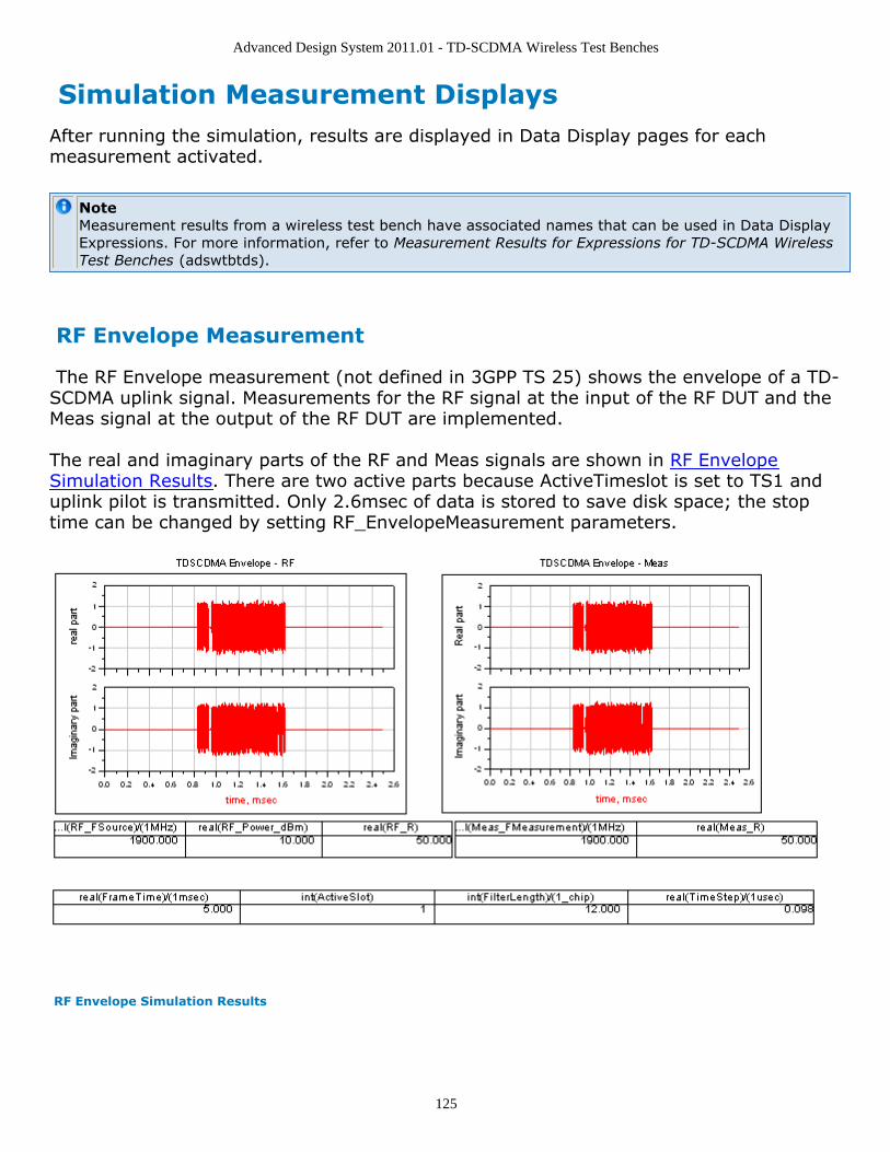
Advanced Design System 2011.01 - TD-SCDMA Wireless Test Benches
125
Simulation Measurement DisplaysAfter running the simulation, results are displayed in Data Display pages for eachmeasurement activated.
NoteMeasurement results from a wireless test bench have associated names that can be used in Data DisplayExpressions. For more information, refer to Measurement Results for Expressions for TD-SCDMA WirelessTest Benches (adswtbtds).
RF Envelope Measurement
The RF Envelope measurement (not defined in 3GPP TS 25) shows the envelope of a TD-SCDMA uplink signal. Measurements for the RF signal at the input of the RF DUT and theMeas signal at the output of the RF DUT are implemented.
The real and imaginary parts of the RF and Meas signals are shown in RF EnvelopeSimulation Results. There are two active parts because ActiveTimeslot is set to TS1 anduplink pilot is transmitted. Only 2.6msec of data is stored to save disk space; the stoptime can be changed by setting RF_EnvelopeMeasurement parameters.
RF Envelope Simulation Results
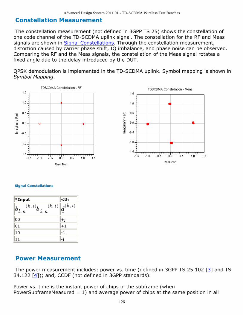
Advanced Design System 2011.01 - TD-SCDMA Wireless Test Benches
126
Constellation Measurement
The constellation measurement (not defined in 3GPP TS 25) shows the constellation ofone code channel of the TD-SCDMA uplink signal. The constellation for the RF and Meassignals are shown in Signal Constellations. Through the constellation measurement,distortion caused by carrier phase shift, IQ imbalance, and phase noise can be observed.Comparing the RF and the Meas signals, the constellation of the Meas signal rotates afixed angle due to the delay introduced by the DUT.
QPSK demodulation is implemented in the TD-SCDMA uplink. Symbol mapping is shown inSymbol Mapping.
Signal Constellations
*Input <th
00 +j
01 +1
10 -1
11 -j
Power Measurement
The power measurement includes: power vs. time (defined in 3GPP TS 25.102 [3] and TS34.122 [4]); and, CCDF (not defined in 3GPP standards).
Power vs. time is the instant power of chips in the subframe (whenPowerSubframeMeasured = 1) and average power of chips at the same position in all
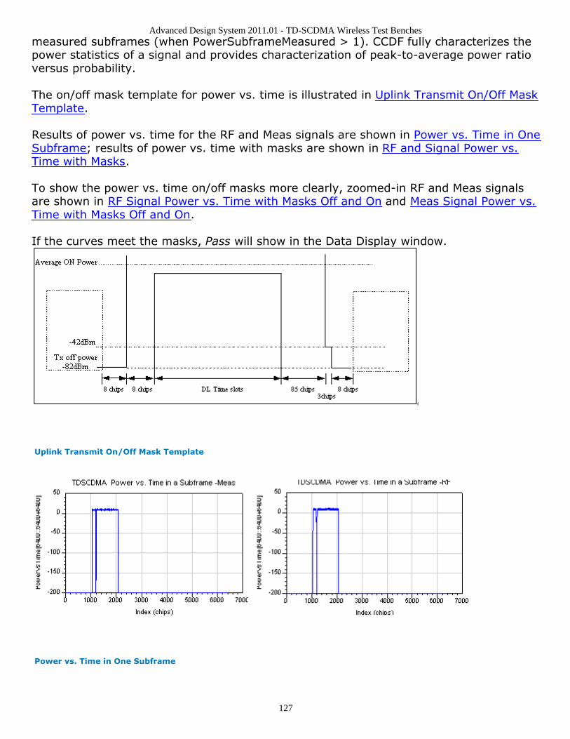
Advanced Design System 2011.01 - TD-SCDMA Wireless Test Benches
127
measured subframes (when PowerSubframeMeasured > 1). CCDF fully characterizes thepower statistics of a signal and provides characterization of peak-to-average power ratioversus probability.
The on/off mask template for power vs. time is illustrated in Uplink Transmit On/Off MaskTemplate.
Results of power vs. time for the RF and Meas signals are shown in Power vs. Time in OneSubframe; results of power vs. time with masks are shown in RF and Signal Power vs.Time with Masks.
To show the power vs. time on/off masks more clearly, zoomed-in RF and Meas signalsare shown in RF Signal Power vs. Time with Masks Off and On and Meas Signal Power vs.Time with Masks Off and On.
If the curves meet the masks, Pass will show in the Data Display window.
Uplink Transmit On/Off Mask Template
Power vs. Time in One Subframe

Advanced Design System 2011.01 - TD-SCDMA Wireless Test Benches
128
RF and Signal Power vs. Time with Masks
RF Signal Power vs. Time with Masks Off and On
Meas Signal Power vs. Time with Masks Off and On

Advanced Design System 2011.01 - TD-SCDMA Wireless Test Benches
129
The CCDF for the RF and the Meas signals are shown in Complementary CumulativeDistribution Function.
The peak-to-average power ratios of the RF and Meas signals are shown in Peak-to-Average Power Ratios.
Complementary Cumulative Distribution Function
Peak-to-Average Power Ratios
Spectrum Measurement
The spectrum measurement (not defined in 3GPP standards) shows the spectrum of theTD-SCDMA uplink signal. The spectrum analyzer output contain complex amplitudevoltage values and the dBm(<meas_name>, <ref_r>) expressions can be used to convertto dBm values. Spectrums for the RF and the Meas signals are shown in TD-SCDMA SignalSpectrums.
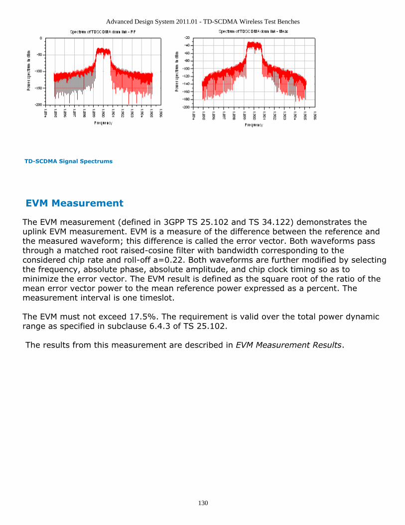
Advanced Design System 2011.01 - TD-SCDMA Wireless Test Benches
130
TD-SCDMA Signal Spectrums
EVM Measurement
The EVM measurement (defined in 3GPP TS 25.102 and TS 34.122) demonstrates theuplink EVM measurement. EVM is a measure of the difference between the reference andthe measured waveform; this difference is called the error vector. Both waveforms passthrough a matched root raised-cosine filter with bandwidth corresponding to theconsidered chip rate and roll-off a=0.22. Both waveforms are further modified by selectingthe frequency, absolute phase, absolute amplitude, and chip clock timing so as tominimize the error vector. The EVM result is defined as the square root of the ratio of themean error vector power to the mean reference power expressed as a percent. Themeasurement interval is one timeslot.
The EVM must not exceed 17.5%. The requirement is valid over the total power dynamicrange as specified in subclause 6.4.3 of TS 25.102.
The results from this measurement are described in EVM Measurement Results.

Advanced Design System 2011.01 - TD-SCDMA Wireless Test Benches
131
Result Description
Avg_ChEVMrms_pct average channel EVM rms in %
ChEVMrms_pct channel EVM rms in % versus subframe
ChEVM_Pk_pct channel peak EVM in % versus subframe
ChEVM_Pk_symbol_idx channel peak EVM symbol index versus subframe
Avg_ChMagErr_rms_pct average channel magnitude error rms in %
ChMagErr_rms_pct channel magnitude error rms in % versus subframe
ChMagErr_Pk_pct channel peak magnitude error in % versus subframe
ChMagErr_Pk_symbol_idx channel peak magnitude error symbol index versus subframe
Avg_ChPhaseErr_deg average channel phase error in degrees
ChPhaseErr_deg channel phase error in degrees versus subframe
ChPhaseErr_Pk_deg channel peak phase error in degrees versus subframe
ChPhaseErr_Pk_symbol_idx channel peak phase error symbol index versus subframe
ChCodePhase_deg channel code phase (phase of the channel code with respect to the pilot) versussubframe
Avg_CompEVMrms_pct average composite EVM rms in %
CompEVMrms_pct composite EVM rms in % versus subframe
CompEVM_Pk_pct composite peak EVM in % versus subframe
CompEVM_Pk_chip_idx composite peak EVM chip index versus subframe
Avg_CompMagErr_rms_pct average composite magnitude error rms in %
CompMagErr_rms_pct composite magnitude error rms in % versus subframe
CompMagErr_Pk_pct composite peak magnitude error in % versus subframe
CompMagErr_Pk_chip_idx composite peak magnitude error chip index versus subframe
Avg_CompPhaseErr_deg average composite phase error in degrees
CompPhaseErr_deg composite phase error in degrees versus subframe
CompPhaseErr_Pk_deg composite peak phase error in degrees versus subframe
CompPhaseErr_Pk_chip_idx composite peak phase error chip index versus subframe
Avg_Rho average rho
Rho rho versus subframe
Avg_FreqError_Hz average frequency error in Hz
FreqError_Hz frequency error in Hz versus subframe
Avg_IQ_Offset_dB average IQ offset in dB
IQ_Offset_dB IQ offset in dB versus subframe
Avg_QuadErr_deg average quadrature error in degrees
QuadErr_deg quadrature error in degrees versus subframe
Avg_GainImb_dB average IQ gain imbalance in dB
IQ_GainImb_dB IQ gain imbalance in dB versus subframe
If EVM_AverageType is set to RMS (Video), EVM will be measured inEVM_SubframesToAverage subframes. If EVM_AverageType is set to Off, EVM will bemeasured in the first subframe detected. Results named with the Avg_ prefix are resultsaveraged over the number of subframes specified by the user inEVM_SubframesToAverage (when EVM_AverageType is set to RMS (Video)). Results thatare not named Avg_ are results versus subframe. RF signal results are shown in RF SignalAverage and Peak EVM; Meas signal results are shown in Meas Signal Average and Peak
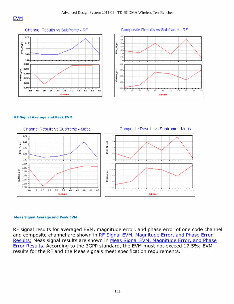
Advanced Design System 2011.01 - TD-SCDMA Wireless Test Benches
132
EVM.
RF Signal Average and Peak EVM
Meas Signal Average and Peak EVM
RF signal results for averaged EVM, magnitude error, and phase error of one code channeland composite channel are shown in RF Signal EVM, Magnitude Error, and Phase ErrorResults; Meas signal results are shown in Meas Signal EVM, Magnitude Error, and PhaseError Results. According to the 3GPP standard, the EVM must not exceed 17.5%; EVMresults for the RF and the Meas signals meet specification requirements.
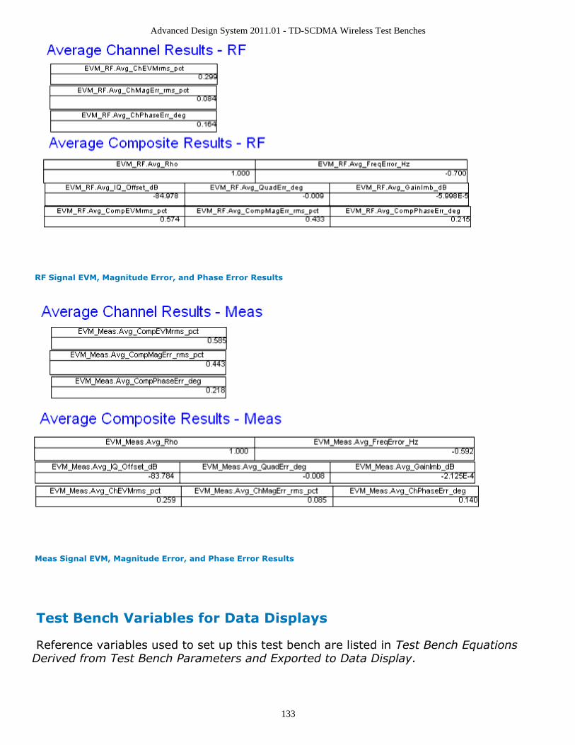
Advanced Design System 2011.01 - TD-SCDMA Wireless Test Benches
133
RF Signal EVM, Magnitude Error, and Phase Error Results
Meas Signal EVM, Magnitude Error, and Phase Error Results
Test Bench Variables for Data Displays
Reference variables used to set up this test bench are listed in Test Bench EquationsDerived from Test Bench Parameters and Exported to Data Display.
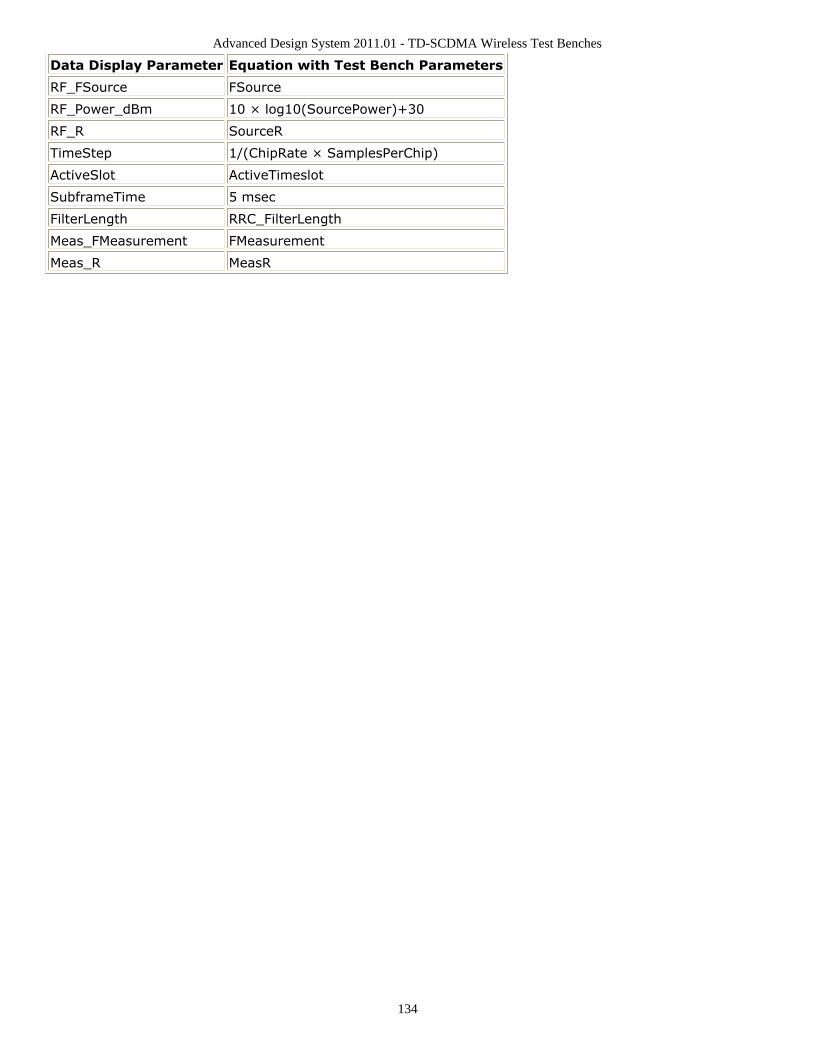
Advanced Design System 2011.01 - TD-SCDMA Wireless Test Benches
134
Data Display Parameter Equation with Test Bench Parameters
RF_FSource FSource
RF_Power_dBm 10 × log10(SourcePower)+30
RF_R SourceR
TimeStep 1/(ChipRate × SamplesPerChip)
ActiveSlot ActiveTimeslot
SubframeTime 5 msec
FilterLength RRC_FilterLength
Meas_FMeasurement FMeasurement
Meas_R MeasR
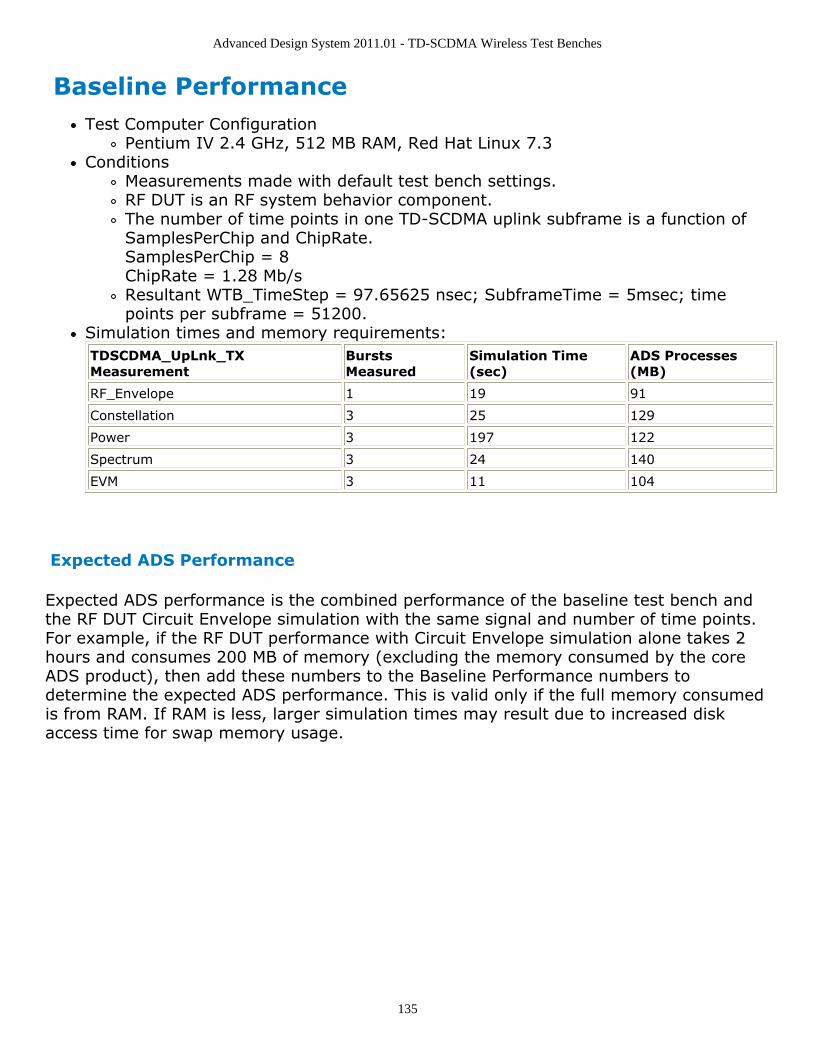
Advanced Design System 2011.01 - TD-SCDMA Wireless Test Benches
135
Baseline PerformanceTest Computer Configuration
Pentium IV 2.4 GHz, 512 MB RAM, Red Hat Linux 7.3Conditions
Measurements made with default test bench settings.RF DUT is an RF system behavior component.The number of time points in one TD-SCDMA uplink subframe is a function ofSamplesPerChip and ChipRate.SamplesPerChip = 8ChipRate = 1.28 Mb/sResultant WTB_TimeStep = 97.65625 nsec; SubframeTime = 5msec; timepoints per subframe = 51200.
Simulation times and memory requirements:TDSCDMA_UpLnk_TXMeasurement
BurstsMeasured
Simulation Time(sec)
ADS Processes(MB)
RF_Envelope 1 19 91
Constellation 3 25 129
Power 3 197 122
Spectrum 3 24 140
EVM 3 11 104
Expected ADS Performance
Expected ADS performance is the combined performance of the baseline test bench andthe RF DUT Circuit Envelope simulation with the same signal and number of time points.For example, if the RF DUT performance with Circuit Envelope simulation alone takes 2hours and consumes 200 MB of memory (excluding the memory consumed by the coreADS product), then add these numbers to the Baseline Performance numbers todetermine the expected ADS performance. This is valid only if the full memory consumedis from RAM. If RAM is less, larger simulation times may result due to increased diskaccess time for swap memory usage.
Advanced Design System 2011.01 - TD-SCDMA Wireless Test Benches
136
References for Uplink Transmitter Test3GPP TS 25.221, "3rd Generation Partnership Project; Technical Specification Group1.Radio Access Network; Physical channels and mapping of transport channels ontophysical channels (TDD) (Release 4)," version 4.5.0, June, 2002.http://www.3gpp.org/ftp/Specs/2002-06/Rel-4/25_series/25221-450.zip ]3GPP TS 25.223, "3rd Generation Partnership Project; Technical Specification Group2.Radio Access Network; Spreading and modulation (TDD) (Release 4)," version 4.4.0,March, 2002.http://www.3gpp.org/ftp/Specs/2002-06/Rel-4/25_series/25223-440.zip ]3GPP TS 25.102, "3rd Generation Partnership Project; Technical Specification Group3.Radio Access Networks; UE Radio Transmission and Reception (TDD) (Release 4),"version 4.5.0, June, 2002.http://www.3gpp.org/ftp/Specs/2002-06/Rel-4/25_series/25102-450.zip ]3GPP TS 34.122, "3rd Generation Partnership Project; Technical Specification Group4.Terminal; Terminal Conformance Specification; Radio Transmission and Reception(TDD) (Release 4)," version 4.4.0, June, 2002.http://www.3gpp.org/ftp/Specs/2002-06/Rel-4/34_series/34122-440.zip ]
Setting up a Wireless Test Bench Analysis in the Wireless Test Bench Simulationdocumentation explains how to use test bench windows and dialogs to perform analysistasks.
Setting Circuit Envelope Analysis Parameters in the Wireless Test Bench Simulationdocumentation explains how to set up circuit envelope analysis parameters such asconvergence criteria, solver selection, and initial guess.
Setting Automatic Verification Modeling Parameters in the Wireless Test Bench Simulationdocumentation explains how to improve simulation speed.


