JOURNAL OF THE KOREAN INSTITUTE OF ELECTROMAGNETIC ENGINEERING AND SCIENCE, VOL. 10, NO. 3, SEP. 2010 JKIEES 2010-10-3-05 104 On the Coexistence among WiMAX-TDD, TD-LTE, and TD-SCDMA Bong Youl Cho Jin Young Kim Abstract With several advantages such as flexible downlink-to-uplink(DL-to-UL) ratio and flexible spectrum usage, Time Division Duplexing(TDD) is emerging as an alternate to Frequency Division Duplexing(FDD), especially in wireless broadband systems. We already have at least four different TDD systems in the industry: Time Division-Synchronous Code Division Multiple Access(TD-SCDMA), IEEE 802.16e-TDD, IEEE 802.16m-TDD, and Time Division-Long Term Evolution(TD-LTE). A disadvantage of TDD is that tight coordination such as time synchronization between adjacent operators is required to prevent interference between the adjacent TDD systems. In this paper, we investigate coexistence scenarios among the above four well-known TDD systems and calculate spectral efficiency(SE) loss in each scenario. Our findings are that SE loss can be significant if TDD ratios of the adjacent operators are considerably different. However, as long as the TDD ratios of the adjacent operators are similar, configurations in the systems permit perfect time synchronization between the two heterogeneous TDD systems, and the resulting SE loss is zero or reasonably low. We believe that the above findings and the configurations of the TDD systems recommended to minimize SE loss will be helpful for operators who deploy TDD systems in system parameter determination and cross-operator coordination. Key words : TDD, WiMAX, TD-LTE, TD-SCDMA, Coexistence. Manuscript received July 23, 2010 ; revised September 1, 2010. (ID No. 20100723-025J) Department of Electronics Convergence Engineering, Kwangwoon University, Seoul, Korea. Corresponding Author : Jin Young Kim (e-mail : [email protected]) Ⅰ. Introduction FDD has been used as a duplexing scheme for the ma- jority of cellular communication systems including IS- 95, cdma2000, wideband code division multiple access (WCDMA), high speed downlink packet access(HS- DPA), high speed uplink packet access(HSUPA), and LTE-FDD. The only TDD-based system that has been meaningful footprint in the industry is TD-SCDMA. Compared with FDD, TDD has several advantages such as flexible DL-to-UL ratio(i.e., TDD ratio), simpler implementation of "smart" antenna techniques, and chea- per transceiver implementation. Consequently, TDD has emerged as another duplexing scheme, especially for wire- less broadband systems such as IEEE 802.16e, IEEE 802.16m, and TD-LTE. A disadvantage of TDD is that TDD system perfor- mance is significantly degraded when DL and UL sig- nals overlap in time. Therefore, TDD first of all requires time synchronization throughout the network within one operator to prevent performance degradation by this over- lap. In addition, TDD requires a large guard band(GB) between the adjacent TDD operators and/or a high level of coordination between the adjacent TDD operators. Coor- dination to reduce interference between adjacent ope- rators can be accomplished in several ways such as time synchronization, general radio network engineering, trans- mit power reduction, and tighter filtering. Among them, time synchronization can be an effective coordination me- thod to reduce interference between adjacent operators [10] . Time synchronization between the same TDD systems (e.g., time synchronization between two adjacent IEEE 802.16e systems) is rather easy. However, if two diffe- rent TDD systems are used in the adjacent spectrum, it can be more difficult to ensure time synchronization since the system parameters of the two different systems may not necessarily be the same. There have been several studies on interference bet- ween DL and UL in TDD systems. Holma et al. eva- luated interference between DL and UL in TDD mode of UMTS terrestrial radio access(UTRA). They also evaluated the synchronization and coordination require- ments of UTRA TDD [1] . In simulation results, Junsong et al. showed that the performance of dynamic TDD is unacceptable due to interference on UL in a cell caused by DL transmissions of other cells when omni-direc- tional antennas are used at BS [2] . Chih-He et al. studied the determination of DL-to-UL ratio for TDD-based IEEE 802.16e systems and proposed a scheme that ad- justs DL-to-UL ratio according to the current traffic pro- file, wireless interference, and transport layer parameters in order to maximize the aggregate throughput of TCP
Transcript
JOURNAL OF THE KOREAN INSTITUTE OF ELECTROMAGNETIC ENGINEERING AND SCIENCE, VOL. 10, NO. 3, SEP. 2010 JKIEES 2010-10-3-05
104
On the Coexistence among WiMAX-TDD, TD-LTE, and TD-SCDMA
Bong Youl Cho․Jin Young Kim
Abstract
With several advantages such as flexible downlink-to-uplink(DL-to-UL) ratio and flexible spectrum usage, Time Division Duplexing(TDD) is emerging as an alternate to Frequency Division Duplexing(FDD), especially in wireless broadband systems. We already have at least four different TDD systems in the industry: Time Division-Synchronous Code Division Multiple Access(TD-SCDMA), IEEE 802.16e-TDD, IEEE 802.16m-TDD, and Time Division-Long Term Evolution(TD-LTE). A disadvantage of TDD is that tight coordination such as time synchronization between adjacent operators is required to prevent interference between the adjacent TDD systems. In this paper, we investigate coexistence scenarios among the above four well-known TDD systems and calculate spectral efficiency(SE) loss in each scenario. Our findings are that SE loss can be significant if TDD ratios of the adjacent operators are considerably different. However, as long as the TDD ratios of the adjacent operators are similar, configurations in the systems permit perfect time synchronization between the two heterogeneous TDD systems, and the resulting SE loss is zero or reasonably low. We believe that the above findings and the configurations of the TDD systems recommended to minimize SE loss will be helpful for operators who deploy TDD systems in system parameter determination and cross-operator coordination.
Key words : TDD, WiMAX, TD-LTE, TD-SCDMA, Coexistence.
Manuscript received July 23, 2010 ; revised September 1, 2010. (ID No. 20100723-025J)Department of Electronics Convergence Engineering, Kwangwoon University, Seoul, Korea.Corresponding Author : Jin Young Kim (e-mail : [email protected])
Ⅰ. Introduction
FDD has been used as a duplexing scheme for the ma-jority of cellular communication systems including IS- 95, cdma2000, wideband code division multiple access (WCDMA), high speed downlink packet access(HS-DPA), high speed uplink packet access(HSUPA), and LTE-FDD. The only TDD-based system that has been meaningful footprint in the industry is TD-SCDMA.
Compared with FDD, TDD has several advantages such as flexible DL-to-UL ratio(i.e., TDD ratio), simpler implementation of "smart" antenna techniques, and chea-per transceiver implementation. Consequently, TDD has emerged as another duplexing scheme, especially for wire-less broadband systems such as IEEE 802.16e, IEEE 802.16m, and TD-LTE.
A disadvantage of TDD is that TDD system perfor-mance is significantly degraded when DL and UL sig-nals overlap in time. Therefore, TDD first of all requires time synchronization throughout the network within one operator to prevent performance degradation by this over-lap. In addition, TDD requires a large guard band(GB) between the adjacent TDD operators and/or a high level of coordination between the adjacent TDD operators. Coor-dination to reduce interference between adjacent ope-rators can be accomplished in several ways such as time
synchronization, general radio network engineering, trans-mit power reduction, and tighter filtering. Among them, time synchronization can be an effective coordination me-thod to reduce interference between adjacent operators[10].
Time synchronization between the same TDD systems (e.g., time synchronization between two adjacent IEEE 802.16e systems) is rather easy. However, if two diffe-rent TDD systems are used in the adjacent spectrum, it can be more difficult to ensure time synchronization since the system parameters of the two different systems may not necessarily be the same.
There have been several studies on interference bet-ween DL and UL in TDD systems. Holma et al. eva-luated interference between DL and UL in TDD mode of UMTS terrestrial radio access(UTRA). They also evaluated the synchronization and coordination require-ments of UTRA TDD[1]. In simulation results, Junsong et al. showed that the performance of dynamic TDD is unacceptable due to interference on UL in a cell caused by DL transmissions of other cells when omni-direc-tional antennas are used at BS[2]. Chih-He et al. studied the determination of DL-to-UL ratio for TDD-based IEEE 802.16e systems and proposed a scheme that ad-justs DL-to-UL ratio according to the current traffic pro-file, wireless interference, and transport layer parameters in order to maximize the aggregate throughput of TCP
CHO and KIM : ON THE COEXISTENCE AMONG WIMAX-TDD, TD-LTE, AND TD-SCDMA
105
based traffic[3]. The following are recent studies on inter- system interference and coexistence scenarios between the different TDD systems in the adjacent spectrum. The article in [4] overviewed the coexistence studies perfor-med in the 3rd generation partnership project(3GPP) radio access network(RAN) Working Group 4 for LTE with other mobile systems, but no specific analysis bet-ween the specific TDD systems such as TD-LTE and IEEE 802.16e-TDD was given. Yihong et al. analyzed coexisting interference between TD-SCDMA and Wi-MAX systems by system simulation[5]. Hui Jia et al. presented performance loss when LTE-TDD system is deployed co-existed with TD-SCDMA system with the assumption that two systems have the similar DL-to-UL ratio[6], and Pei Chang et al. investigated mutual inter-ference between TD-SCDMA system and TD-LTE sys-tem with the minimum coupling loss(MCL) method to analyze isolation requirements[7]. However, most results so far were obtained by simulations, and the coexistence analysis based on the specific system parameters of the different TDD systems was not fully investigated. More-over, neither coordination among the different TDD sys-tems to achieve time synchronization nor the impact on the SE of these systems has been discussed intensively. It should be noted that two different definitions are used for SE loss in this paper: 1) soft SE loss, which is obtained from system level simulation(SLS) and is the definition used in Section Ⅲ; and 2) hard SE loss, which is calculated from system parameter analysis and is the definition used in Section V.
TDD is gaining ground, and there are already at least four different TDD systems in the industry: TD-SCDMA, IEEE 802.16e-TDD, IEEE 802.16m-TDD, and TD-LTE, which means that there is a strong possibility of having the different TDD systems in the adjacent spectrum in the future. Therefore, it is very important to investigate possible interference between the adjacent TDD systems with the specific system parameters of the above four TDD systems and to analyze the anticipated impact of coordination to achieve coexistence.
This paper is organized as follows. First, the advan-tageous features of TDD system are explained in detail in Section Ⅱ. Secondly, the time synchronization require-ment, which is one of the disadvantageous features of the TDD system, is explained in Section Ⅲ. We over-view the four famous TDD systems(IEEE 802.16e-TDD, IEEE 802.16m-TDD, TD-LTE, and TD-SCDMA) focu-sing on their frame and/or subframe structures and TDD ratios in Section Ⅳ. In Section Ⅴ, the coexistence sce-narios among these four TDD systems are analyzed toge-ther with their associated TDD ratios and anticipated SE loss. Finally, we conclude the paper in Section Ⅵ.
Ⅱ. TDD Systems Advantages
Traditional mobile radio systems were built primarily for voice applications which are symmetric in nature. However, today’s broadband internet applications are ge-nerally asymmetric, so it is very difficult to predict how this characteristic will change over time with applica-tions such as digital broadcasting and multicasting which require even higher usage on the DL, and voice over IP(VoIP) which results in more symmetric usage. There-fore, we need a duplexing technology that can acco-mmodate unpredictable changes in future usage models for wireless broadband access. In TDD systems, the ra-tio of bandwidth(BW) dedicated to DL and UL can be adjusted based on actual traffic demand. The flexibility of TDD systems can lead to a more efficient use in a valuable spectrum.
Smart antenna techniques can provide better SE and coverage in cellular deployments. TDD systems enable the simpler implementation and operation of smart ante-nna techniques with the reciprocal feature of DL and UL channels. While FDD systems would generally re-quire fairly accurate channel feedback from mobile stations(MS) to the BS for DL spatial processing, BSs in TDD systems can get DL channel characteristics based on UL channel estimation thanks to channel reciprocity as long as DL and UL paths are well calibrated.
TDD is also generally more flexible for deployment because it does not require a paired spectrum. Therefore, technically it is feasible to deploy TDD systems even in FDD spectrum allocations. In addition, while there should always be a duplexing gap between DL and UL in FDD systems, TDD does not require a duplexing gap.
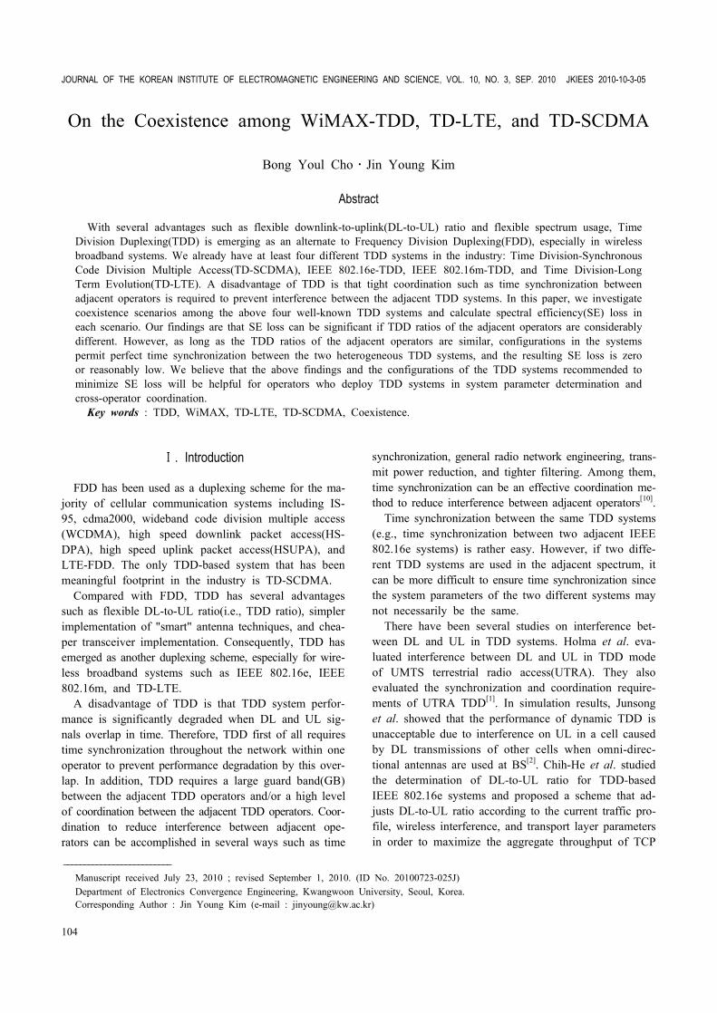
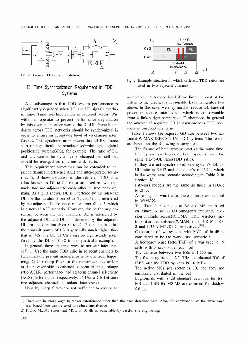
Other advantages of TDD systems include lower costs of hardware both on the MS and the BS. TDD systems avoid the need for expensive duplexers(or diplexers) and require less RF front-end customization for operating in different bands and different regulatory requirements. Fig. 1 shows a typical FDD radio solution and Fig. 2 shows a typical TDD radio solution, respectively. As shown in Fig. 1 and Fig. 2, significantly fewer components are used in the TDD radio solution.
Fig. 1. Typical FDD radio solution.
JOURNAL OF THE KOREAN INSTITUTE OF ELECTROMAGNETIC ENGINEERING AND SCIENCE, VOL. 10, NO. 3, SEP. 2010
106
Fig. 2. Typical TDD radio solution.
Ⅲ. Time Synchronization Requirement in TDD Systems
A disadvantage is that TDD system performance is significantly degraded when DL and UL signals overlap in time. Time synchronization is required across BSs within an operator to prevent performance degradation by this overlap. In other words, the DL/UL frame boun-daries across TDD networks should be synchronized in order to ensure an acceptable level of co-channel inter-ference. This synchronization means that all BSs frame start timings should be synchronized―through a global positioning system(GPS), for example. The ratio of DL and UL cannot be dynamically changed per cell but should be changed on a system-wide basis.
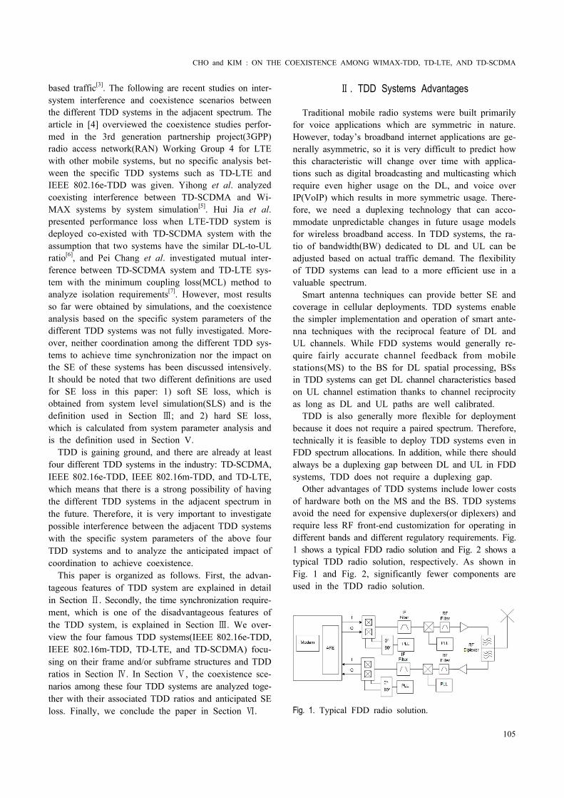
This requirement sometimes can be extended to ad-jacent channel interference(ACI) and inter-operator scena-rios. Fig. 3 shows a situation in which different TDD ratios (also known as DL-to-UL ratio) are used in two cha-nnels that are adjacent to each other in frequency do-main. As Fig. 3 shows, DL is interfered by the adjacent DL for the duration from t0 to t1, and UL is interfered by the adjacent UL for the duration from t2 to t3, which is a normal ACI scenario. However, due to the asynch-ronism between the two channels, UL is interfered by the adjacent DL and DL is interfered by the adjacent UL for the duration from t1 to t2. Given the fact that the transmit power of BS is generally much higher than that of MS, the UL of Ch-1 can be significantly inter-fered by the DL of Ch-2 in this particular example.
In general, there are three ways to mitigate interferen-ce1): 1) Use the same TDD ratio in adjacent channels to fundamentally prevent interference situations from happe-ning; 2) Use sharp filters at the transmitter side and/or at the receiver side to enhance adjacent channel leakage ratio(ACLR) performance and adjacent channel selectivity (ACS) performance, respectively; 3) Use a GB between two adjacent channels to reduce interference.
Usually, sharp filters are not sufficient to ensure an
Fig. 3. Example situation in which different TDD ratios are used in two adjacent channels.
acceptable interference level if we limit the cost of the filters to the practically reasonable level in number two above. In this case, we may need to reduce DL transmit power to reduce interference, which is not desirable from a link-budget perspective. Furthermore, in general the amount of required GB in asynchronous TDD sys-tems is unacceptably large.
Table 1 shows the required GB size between two ad-jacent WiMAX IEEE 802.16e-TDD systems. The results are based on the following assumptions. ․The frames of both systems start at the same time.․If they are synchronized, both systems have the
same DL-to-UL ratio(TDD ratio). ․If they are not synchronized, one system’s DL-to-
UL ratio is 35:12 and the other’s is 26:21, which is the worst case scenario according to Table 2 in Section Ⅳ.1.
․Path-loss models are the same as those in ITU-R M.2113.
․Assuming the worst case, there is no power control in WiMAX.
․The filter characteristics at BS and MS are based on Annex. 6. IMT-2000 orthogonal frequency divi-sion multiple access(OFDMA) TDD wireless me-tropolitan area network(WMAN) of ITU-R M.1580- 2 and ITU-R M.1581-2, respectively[8],[9].
․Co-location of two systems with MCL of 50 dB is considered to be the worst case scenario2).
․A frequency reuse factor(FRF) of 1 was used in 19 cells with 3 sectors per each cell.
․The distance between two BSs is 1,500 m.․The frequency band is 2.5 GHz and channel BW of
IEEE 802.16e-TDD systems is 10 MHz.․The active MSs per sector is 10, and they are
uniformly distributed in the cell.․Lognormals with 8 dB standard deviation for BS-
MS and 4 dB for MS-MS are assumed for shadow fading.
1) There can be more ways to reduce interference other than the ones described here. Also, the combination of the three ways mentioned here can be used to reduce interference.
2) ITU-R M.2045 states that MCL of 70 dB is achievable by careful site engineering.
CHO and KIM : ON THE COEXISTENCE AMONG WIMAX-TDD, TD-LTE, AND TD-SCDMA
107
․Typical BS parameters are used: 36 dBm Tx power, 18 dBi antenna gain, 30 m antenna height, and 3 dB noise figure(NF).
․Typical MS parameters are used: 20 dBm Tx po-wer, 0 dBi antenna gain, 1.5 m antenna height, and 5 dB NF.
․Both co-channel interference(CCI) from the desired system and ACI from the interfering system are considered in calculating signal-to-interference and noise ratio(SINR).
․The amount of required GB is obtained as the points where the victim system’s SE loss is less than 5 % and 10 %, respectively.
As briefly mentioned in Section I, SE loss here is obtained from SLS based on the simulation assumptions described above. Therefore, the required GB size in Table 1 means that the victim system’s capacity will be reduced further below 95 % or below 90 % compared with its original capacity if the GB size assigned bet-ween the adjacent systems is less than the minimum re-quired size. It is important to see that a very big GB that is more than 10 MHz is still required even though we compromise 10 % SE loss in the victim system.
Please note that GB requirements in Table 1 do not take into account any other interference mitigation te-chniques such as tighter TX/RX filters for BS and MS, additional RF filtering for BS, or site engineering in the BS to BS case. If other interference mitigation techni-ques are used, the required GB size can be reduced. However, the results in Table 1 show that time syn-chronization is one of the most efficient coordination schemes to reduce interference between the adjacent sys-tems.
Similar results can be found in [10], and it is entirely possible for time synchronized TDD systems to operate satisfactorily in adjacent frequency blocks with zero guard frequency.
Therefore, it is desirable to have the same TDD ratio on a system-wide basis across adjacent channels as well as in co-channel. However, it is true that this require- Table 1. Required GB size in time synchronized and non-synchronized adjacent 802.16e systems.
Interference path GB required to limit SE loss of victim system by 5 %
GB required to limit SE loss of victim system by 10 %
Time synchronizedBS to MS 0 0
MS to BS 0 0
Time non-synchronizedMS to MS 4 MHz 0
BS to BS >10 MHz >10 MHz
ment forces different operators to use the same TDD ratioif the adjacent channels are owned by the different opera-tors. This requirement may limit operators’ flexibility in their respective business models.
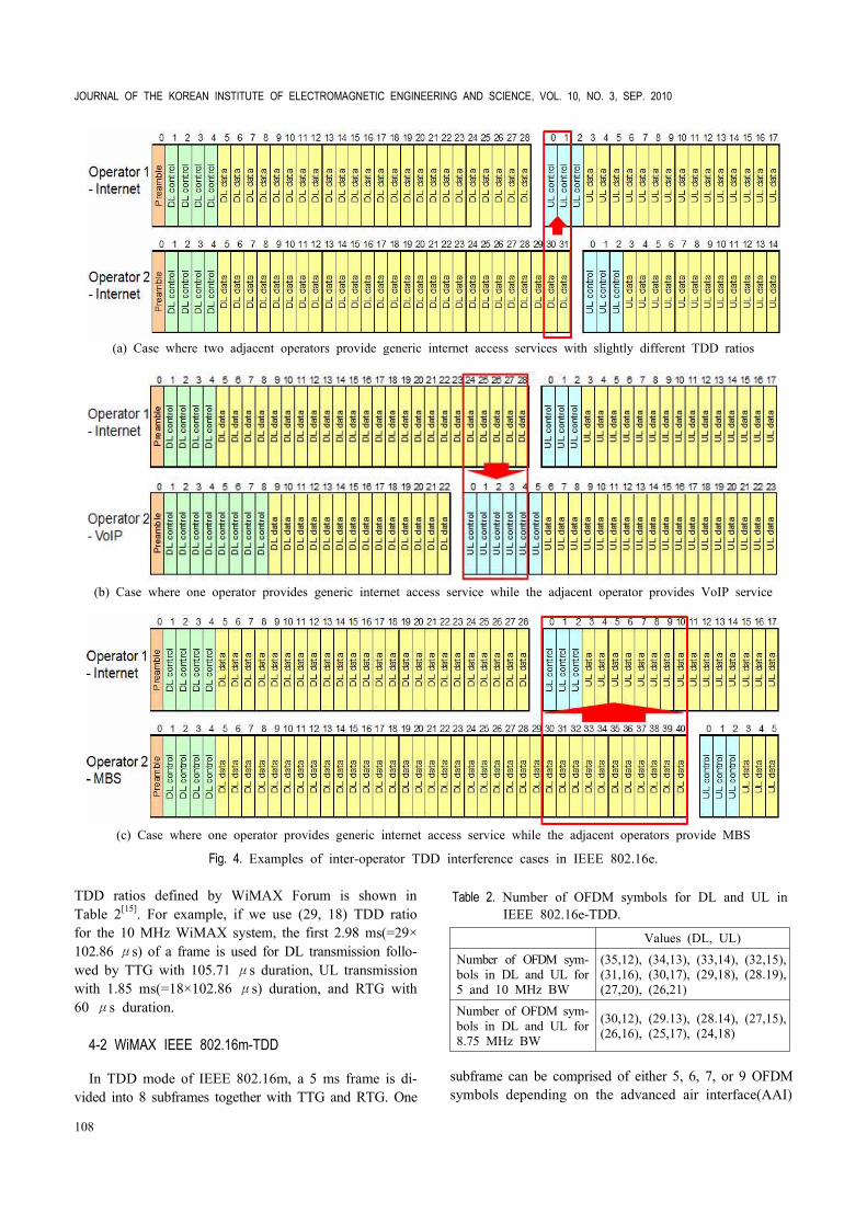
Fig. 4 shows different interference cases per operator business models assuming all operators are using IEEE 802.16e systems. Fig. 4(a) is a case where two adjacent operators provide generic internet access services but use slightly different TDD ratios. Fig. 4(b) is a case where one operator provides generic internet access service while the adjacent operator provides VoIP service, which leads to a significantly different TDD ratio from the one used for the internet service. Finally, Fig. 4(c) is a case where one operator provides generic internet access service while the adjacent operators provide multicast broadcast service (MBS), which also leads to a significantly different TDD ratio from the one for the internet service. The amount of interference in these three cases varies significantly as shown in Fig. 4.
Ⅳ. TDD Ratios of Cellular Communication Systems
The following section reviews several TDD-based cellu-lar communication systems and summarizes TDD ratios.
4-1 WiMAX IEEE 802.16e-TDD
The TDD frame duration of IEEE 802.16e is 5 ms. Each frame in DL transmission begins with a preamble followed by a DL transmission period and a UL trans-mission period. In each frame, the transmit-to-receive time gap(TTG) shall be inserted between DL and UL, and the receive-to-transmit time gap(RTG) shall be inser-ted between the UL and DL at the end of each frame, respectively, to allow BS to turn around[11],[12].
The duration of the cyclic prefix(CP) is 1/8 Tb in IEEE 802.16e. By excluding the switching times(TTG and RTG), there are 47 OFDM symbols per 5 ms frame for 5 and 10 MHz BW and 42 OFDM symbols per 5 ms frame for 8.75 MHz BW3). The number of different
3) For 5 and 10 MHz BW, TTG duration is 105.71 μs, RTG duration is 60 μs, and OFDM symbol duration is 102.86 μs, respectively. For 8.75 MHz BW, TTG duration is 87.2 μs, RTG duration is 74.4 μs, and OFDM symbol duration is 115.2 μs, respectively.
JOURNAL OF THE KOREAN INSTITUTE OF ELECTROMAGNETIC ENGINEERING AND SCIENCE, VOL. 10, NO. 3, SEP. 2010
108
(a) Case where two adjacent operators provide generic internet access services with slightly different TDD ratios
(b) Case where one operator provides generic internet access service while the adjacent operator provides VoIP service
(c) Case where one operator provides generic internet access service while the adjacent operators provide MBS
Fig. 4. Examples of inter-operator TDD interference cases in IEEE 802.16e.
TDD ratios defined by WiMAX Forum is shown in Table 2[15]. For example, if we use (29, 18) TDD ratio for the 10 MHz WiMAX system, the first 2.98 ms(=29× 102.86 μs) of a frame is used for DL transmission follo-wed by TTG with 105.71 μs duration, UL transmission with 1.85 ms(=18×102.86 μs) duration, and RTG with 60 μs duration.
4-2 WiMAX IEEE 802.16m-TDD
In TDD mode of IEEE 802.16m, a 5 ms frame is di-vided into 8 subframes together with TTG and RTG. One
Table 2. Number of OFDM symbols for DL and UL in IEEE 802.16e-TDD.
Values (DL, UL)Number of OFDM sym-bols in DL and UL for 5 and 10 MHz BW
subframe can be comprised of either 5, 6, 7, or 9 OFDM symbols depending on the advanced air interface(AAI)
CHO and KIM : ON THE COEXISTENCE AMONG WIMAX-TDD, TD-LTE, AND TD-SCDMA
109
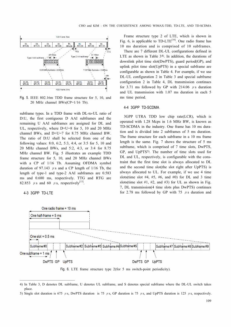
Fig. 5. IEEE 802.16m TDD frame structure for 5, 10, and 20 MHz channel BWs(CP=1/16 Tb).
subframe types. In a TDD frame with DL-to-UL ratio of D:U, the first contiguous D AAI subframes and the remaining U AAI subframes are assigned for DL and UL, respectively, where D+U=8 for 5, 10 and 20 MHz channel BWs, and D+U=7 for 8.75 MHz channel BW. The ratio of D:U shall be selected from one of the following values: 8:0, 6:2, 5:3, 4:4, or 3:5 for 5, 10 and 20 MHz channel BWs, and 5:2, 4:3, or 3:4 for 8.75 MHz channel BW. Fig. 5 illustrates an example TDD frame structure for 5, 10, and 20 MHz channel BWs with a CP of 1/16 Tb. Assuming OFDMA symbol duration of 97.143 μs and a CP length of 1/16 Tb, the length of type-1 and type-2 AAI subframes are 0.583 ms and 0.680 ms, respectively. TTG and RTG are 82.853 μs and 60 μs, respectively[13].
4-3 3GPP TD-LTE
Fig. 6. LTE frame structure type 2(for 5 ms switch-point periodicity).
Frame structure type 2 of LTE, which is shown in Fig. 6, is applicable to TD-LTE[16]. One radio frame has 10 ms duration and is comprised of 10 subframes.
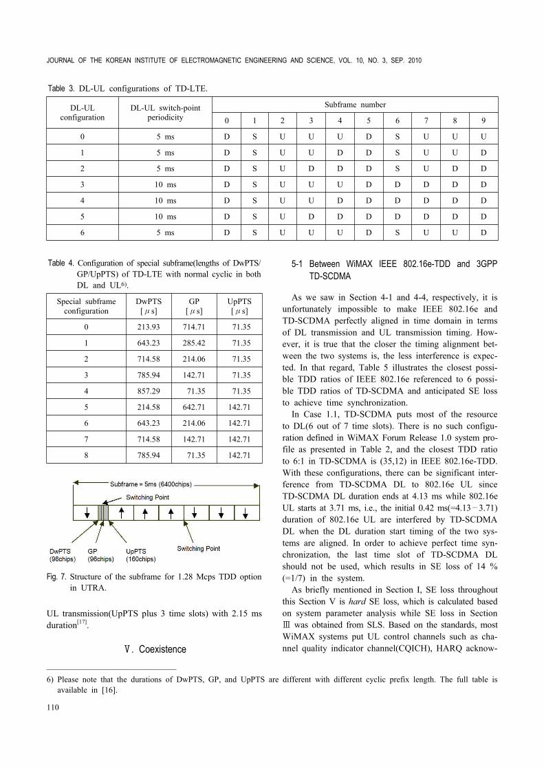
There are 7 different DL-UL configurations defined inLTE as shown in Table 34). In addition, the durations of downlink pilot time slot(DwPTS), guard period(GP), and uplink pilot time slot(UpPTS) in a special subframe are configurable as shown in Table 4. For example, if we use DL-UL configuration 2 in Table 3 and special subframe configuration 2 in Table 4, DL transmission continues for 3.71 ms followed by GP with 214.06 μs duration and UL transmission with 1.07 ms duration in each 5 ms time period.
4-4 3GPP TD-SCDMA
3GPP UTRA TDD low chip rate(LCR), which is operated with 1.28 Mcps in 1.6 MHz BW, is known as TD-SCDMA in the industry. One frame has 10 ms dura-tion and is divided into 2 subframes of 5 ms duration. The frame structure for each subframe in a 10 ms frame length is the same. Fig. 7 shows the structure of 5 ms subframe, which is comprised of 7 time slots, DwPTS, GP, and UpPTS5). The number of time slots used for DL and UL, respectively, is configurable with the cons-traint that the first time slot is always allocated to DL and the second time slot(the slot right after UpPTS) is always allocated to UL. For example, if we use 4 time slots(time slot #4, #5, #6, and #0) for DL and 3 time slots(time slot #1, #2, and #3) for UL as shown in Fig. 7, DL transmission(4 time slots plus DwPTS) continues for 2.78 ms followed by GP with 75 μs duration and
4) In Table 3, D denotes DL subframe, U denotes UL subframe, and S denotes special subframe where the DL-UL switch takes place.
5) Single slot duration is 675 μs, DwPTS duration is 75 μs, GP duration is 75 μs, and UpPTS duration is 125 μs, respectively.
JOURNAL OF THE KOREAN INSTITUTE OF ELECTROMAGNETIC ENGINEERING AND SCIENCE, VOL. 10, NO. 3, SEP. 2010
110
Table 3. DL-UL configurations of TD-LTE.
DL-ULconfiguration
DL-UL switch-point periodicity
Subframe number
0 1 2 3 4 5 6 7 8 9
0 5 ms D S U U U D S U U U
1 5 ms D S U U D D S U U D
2 5 ms D S U D D D S U D D
3 10 ms D S U U U D D D D D
4 10 ms D S U U D D D D D D
5 10 ms D S U D D D D D D D
6 5 ms D S U U U D S U U D
Table 4. Configuration of special subframe(lengths of DwPTS/ GP/UpPTS) of TD-LTE with normal cyclic in both DL and UL6).
Special subframe configuration
DwPTS[μs]
GP[μs]
UpPTS[μs]
0 213.93 714.71 71.35
1 643.23 285.42 71.35
2 714.58 214.06 71.35
3 785.94 142.71 71.35
4 857.29 71.35 71.35
5 214.58 642.71 142.71
6 643.23 214.06 142.71
7 714.58 142.71 142.71
8 785.94 71.35 142.71
Fig. 7. Structure of the subframe for 1.28 Mcps TDD option in UTRA.
UL transmission(UpPTS plus 3 time slots) with 2.15 ms duration[17].
Ⅴ. Coexistence
5-1 Between WiMAX IEEE 802.16e-TDD and 3GPP TD-SCDMA
As we saw in Section 4-1 and 4-4, respectively, it is unfortunately impossible to make IEEE 802.16e and TD-SCDMA perfectly aligned in time domain in terms of DL transmission and UL transmission timing. How-ever, it is true that the closer the timing alignment bet-ween the two systems is, the less interference is expec-ted. In that regard, Table 5 illustrates the closest possi-ble TDD ratios of IEEE 802.16e referenced to 6 possi-ble TDD ratios of TD-SCDMA and anticipated SE loss to achieve time synchronization.
In Case 1.1, TD-SCDMA puts most of the resource to DL(6 out of 7 time slots). There is no such configu-ration defined in WiMAX Forum Release 1.0 system pro-file as presented in Table 2, and the closest TDD ratio to 6:1 in TD-SCDMA is (35,12) in IEEE 802.16e-TDD. With these configurations, there can be significant inter-ference from TD-SCDMA DL to 802.16e UL since TD-SCDMA DL duration ends at 4.13 ms while 802.16e UL starts at 3.71 ms, i.e., the initial 0.42 ms(=4.13—3.71) duration of 802.16e UL are interfered by TD-SCDMA DL when the DL duration start timing of the two sys-tems are aligned. In order to achieve perfect time syn-chronization, the last time slot of TD-SCDMA DL should not be used, which results in SE loss of 14 % (=1/7) in the system.
As briefly mentioned in Section I, SE loss throughout this Section V is hard SE loss, which is calculated based on system parameter analysis while SE loss in Section Ⅲ was obtained from SLS. Based on the standards, most WiMAX systems put UL control channels such as cha-nnel quality indicator channel(CQICH), HARQ acknow-
6) Please note that the durations of DwPTS, GP, and UpPTS are different with different cyclic prefix length. The full table is available in [16].
CHO and KIM : ON THE COEXISTENCE AMONG WIMAX-TDD, TD-LTE, AND TD-SCDMA
111
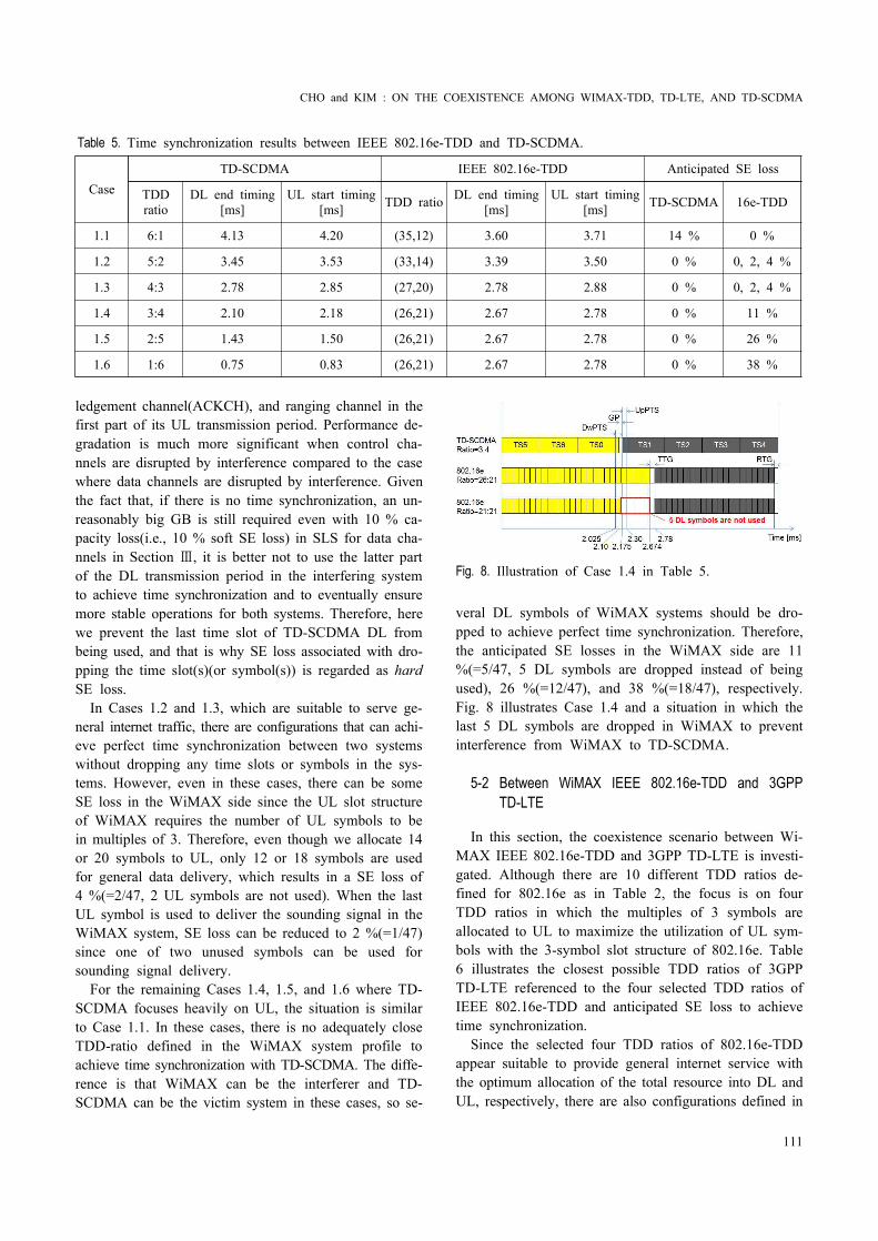
Table 5. Time synchronization results between IEEE 802.16e-TDD and TD-SCDMA.
CaseTD-SCDMA IEEE 802.16e-TDD Anticipated SE loss
TDD ratio
DL end timing [ms]
UL start timing [ms] TDD ratio DL end timing
[ms]UL start timing
[ms] TD-SCDMA 16e-TDD
1.1 6:1 4.13 4.20 (35,12) 3.60 3.71 14 % 0 %
1.2 5:2 3.45 3.53 (33,14) 3.39 3.50 0 % 0, 2, 4 %
1.3 4:3 2.78 2.85 (27,20) 2.78 2.88 0 % 0, 2, 4 %
1.4 3:4 2.10 2.18 (26,21) 2.67 2.78 0 % 11 %
1.5 2:5 1.43 1.50 (26,21) 2.67 2.78 0 % 26 %
1.6 1:6 0.75 0.83 (26,21) 2.67 2.78 0 % 38 %
ledgement channel(ACKCH), and ranging channel in the first part of its UL transmission period. Performance de-gradation is much more significant when control cha-nnels are disrupted by interference compared to the case where data channels are disrupted by interference. Given the fact that, if there is no time synchronization, an un-reasonably big GB is still required even with 10 % ca-pacity loss(i.e., 10 % soft SE loss) in SLS for data cha-nnels in Section Ⅲ, it is better not to use the latter part of the DL transmission period in the interfering system to achieve time synchronization and to eventually ensure more stable operations for both systems. Therefore, here we prevent the last time slot of TD-SCDMA DL from being used, and that is why SE loss associated with dro-pping the time slot(s)(or symbol(s)) is regarded as hard SE loss.
In Cases 1.2 and 1.3, which are suitable to serve ge-neral internet traffic, there are configurations that can achi-eve perfect time synchronization between two systems without dropping any time slots or symbols in the sys-tems. However, even in these cases, there can be some SE loss in the WiMAX side since the UL slot structure of WiMAX requires the number of UL symbols to be in multiples of 3. Therefore, even though we allocate 14 or 20 symbols to UL, only 12 or 18 symbols are used for general data delivery, which results in a SE loss of 4 %(=2/47, 2 UL symbols are not used). When the last UL symbol is used to deliver the sounding signal in the WiMAX system, SE loss can be reduced to 2 %(=1/47) since one of two unused symbols can be used for sounding signal delivery.
For the remaining Cases 1.4, 1.5, and 1.6 where TD- SCDMA focuses heavily on UL, the situation is similar to Case 1.1. In these cases, there is no adequately close TDD-ratio defined in the WiMAX system profile to achieve time synchronization with TD-SCDMA. The diffe-rence is that WiMAX can be the interferer and TD- SCDMA can be the victim system in these cases, so se-
Fig. 8. Illustration of Case 1.4 in Table 5.
veral DL symbols of WiMAX systems should be dro-pped to achieve perfect time synchronization. Therefore, the anticipated SE losses in the WiMAX side are 11 %(=5/47, 5 DL symbols are dropped instead of being used), 26 %(=12/47), and 38 %(=18/47), respectively. Fig. 8 illustrates Case 1.4 and a situation in which the last 5 DL symbols are dropped in WiMAX to prevent interference from WiMAX to TD-SCDMA.
5-2 Between WiMAX IEEE 802.16e-TDD and 3GPP TD-LTE
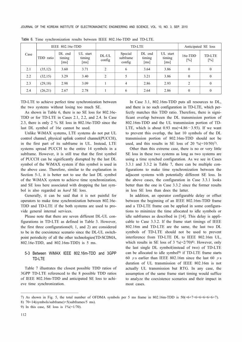
In this section, the coexistence scenario between Wi-MAX IEEE 802.16e-TDD and 3GPP TD-LTE is investi-gated. Although there are 10 different TDD ratios de-fined for 802.16e as in Table 2, the focus is on four TDD ratios in which the multiples of 3 symbols are allocated to UL to maximize the utilization of UL sym-bols with the 3-symbol slot structure of 802.16e. Table 6 illustrates the closest possible TDD ratios of 3GPP TD-LTE referenced to the four selected TDD ratios of IEEE 802.16e-TDD and anticipated SE loss to achieve time synchronization.
Since the selected four TDD ratios of 802.16e-TDD appear suitable to provide general internet service with the optimum allocation of the total resource into DL and UL, respectively, there are also configurations defined in
JOURNAL OF THE KOREAN INSTITUTE OF ELECTROMAGNETIC ENGINEERING AND SCIENCE, VOL. 10, NO. 3, SEP. 2010
112
Table 6. Time synchronization results between IEEE 802.16e-TDD and TD-LTE.
Case
IEEE 802.16e-TDD TD-LTE Anticipated SE loss
TDD ratioDL end timing[ms]
UL start timing[ms]
DL-UL config
Special subframe
config
DL end timing[ms]
UL start timing[ms]
16e-TDD[%]
TD-LTE[%]
2.1 (35,12) 3.60 3.71 2 6 3.64 3.86 0 0
2.2 (32,15) 3.29 3.40 2 5 3.21 3.86 0 0
2.3 (29,18) 2.98 3.09 1 4 2.86 2.93 2 0
2.4 (26,21) 2.67 2.78 1 6 2.64 2.86 0 0
TD-LTE to achieve perfect time synchronization between the two systems without losing too much SE.
As shown in Table 6, there is no SE loss for 802.16e- TDD or for TD-LTE in Cases 2.1, 2.2, and 2.4. In Case 2.3, there is only 2 % SE loss in 802.16e-TDD since the last DL symbol of 16e cannot be used.
Unlike WiMAX systems, LTE systems do not put UL control channel, physical uplink control channel(PUCCH), in the first part of its subframe in UL. Instead, LTE systems spread PUCCH to the entire 14 symbols in a subframe. However, it is still true that the first symbol of PUCCH can be significantly disrupted by the last DL symbol of the WiMAX system if this symbol is used in the above case. Therefore, similar to the explanation in Section 5-1, it is better not to use the last DL symbol of the WiMAX system to achieve time synchronization, and SE loss here associated with dropping the last sym-bol is also regarded as hard SE loss.
Generally, it can be said that it is not painful for operators to make time synchronization between 802.16e- TDD and TD-LTE if the both systems are used to pro-vide general internal services.
Please note that there are seven different DL-UL con-figurations in TD-LTE as defined in Table 3. However, the first three configurations(0, 1, and 2) are considered to be in the coexistence scenario since the DL-UL switch- point periodicity of all the other technologies(TD-SCDMA, 802.16e-TDD, and 802.16m-TDD) is 5 ms.
5-3 Between WiMAX IEEE 802.16m-TDD and 3GPP TD-LTE
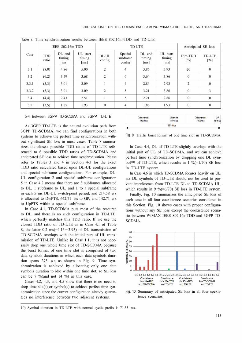
Table 7 illustrates the closest possible TDD ratios of 3GPP TD-LTE referenced to the 8 possible TDD ratios of IEEE 802.16m-TDD and anticipated SE loss to achi-eve time synchronization.
In Case 3.1, 802.16m-TDD puts all resources to DL, and there is no such configuration in TD-LTE, which per-fectly matches this TDD ratio. Therefore, there is signi-ficant overlap between the DL transmission portion of 802.16m-TDD and the UL transmission portion of TD- LTE, which is about 0.93 ms(=4.86—3.93). If we want to prevent this overlap, the last 10 symbols of the DL transmission portion of 802.16m-TDD should not be used, and this results in SE loss of 20 %(=10/50)7).
Other than this extreme case, there is no or very little SE loss in these two systems as long as two systems are using a time synched configuration. As we see in Cases 3.3.1 and 3.3.2 in Table 7, there can be multiple con-figurations to make time synchronization between the adjacent systems with potentially different SE loss. In the above cases, the configuration in Case 3.3.1 looks better than the one in Case 3.3.2 since the former results in less SE loss than does the latter.
In addition, an operator configurable delay or offset between the beginning of an IEEE 802.16m-TDD frame and a TD-LTE frame can be applied in some configura-tions to minimize the time allocated to idle symbols or idle subframes as described in [14]. This delay is appli-cable to Case 3.3.2. If the frame start timings of IEEE 802.16m and TD-LTE are the same, the last two DL symbols of TD-LTE should not be used to prevent interference from TD-LTE DL to IEEE 802.16m UL, which results in SE loss of 3 %(=2/70)8). However, only the last single DL symbol(instead of two) of TD-LTE can be allocated to idle symbol9) if TD-LTE frame starts 60 μs earlier than IEEE 802.16m since the last 60 μs duration of UL transmission of IEEE 802.16m is not actually UL transmission but RTG. In any case, the assumption of the same frame start timing would suffice to analyze the coexistence scenarios and their impact in most cases.
7) As shown in Fig. 5, the total number of OFDMA symbols per 5 ms frame in 802.16m-TDD is 50(=6+7+6+6+6+6+6+7).8) 70=14(symbols/subframe)×5(subframes/5 ms).9) In this case, SE loss is 1%(=1/70).
CHO and KIM : ON THE COEXISTENCE AMONG WIMAX-TDD, TD-LTE, AND TD-SCDMA
113
Table 7. Time synchronization results between IEEE 802.16m-TDD and TD-LTE.
Case
IEEE 802.16m-TDD TD-LTE Anticipated SE loss
TDD ratio
DL end timing[ms]
UL start timing[ms]
DL-UL config
Special subframe
config
DL end timing[ms]
UL start timing[ms]
16m-TDD[%]
TD-LTE[%]
3.1 (8,0) 4.86 5.00 2 4 3.86 3.93 20 0
3.2 (6,2) 3.59 3.68 2 6 3.64 3.86 0 0
3.3.1 (5,3) 3.01 3.09 1 4 2.86 2.93 2 0
3.3.2 (5,3) 3.01 3.09 2 5 3.21 3.86 0 3
3.4 (4,4) 2.43 2.51 1 5 2.21 2.86 0 0
3.5 (3,5) 1.85 1.93 0 4 1.86 1.93 0 0
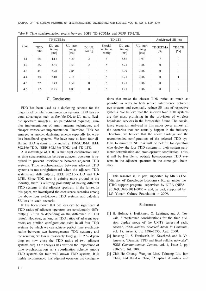
5-4 Between 3GPP TD-SCDMA and 3GPP TD-LTE
As 3GPP TD-LTE is the natural evolution path from 3GPP TD-SCDMA, we can find configurations in both systems to achieve the perfect time synchronization with-out significant SE loss in most cases. Table 8 summa-rizes the closest possible TDD ratios of TD-LTE refe-renced to 6 possible TDD ratios of TD-SCDMA and anticipated SE loss to achieve time synchronization. Please refer to Tables 3 and 4 in Section 4-3 for the exact TDD ratio calculated based upon DL-UL configurations and special subframe configurations. For example, DL- UL configuration 2 and special subframe configuration 5 in Case 4.2 means that there are 3 subframes allocated to DL, 1 subframe to UL, and 1 to a special subframe in each 5 ms DL-UL switch-point period, and 214.58 μs is allocated to DwPTS, 642.71 μs to GP, and 142.71 μs to UpPTS within a special subframe.
In Case 4.1, TD-SCDMA puts most of the resource to DL, and there is no such configuration in TD-LTE, which perfectly matches this TDD ratio. If we use the closest TDD ratio of TD-LTE as in Case 4.1 of Table 8, the latter 0.2 ms(=4.13—3.93) of DL transmission of TD-SCDMA overlaps with the initial part of UL trans-mission of TD-LTE. Unlike in Case 1.1, it is not nece-ssary drop one whole time slot of TD-SCDMA because the burst format of one time slot is comprised of two data symbols durations in which each data symbols dura-tion spans 275 μs as shown in Fig. 9. Time syn-chronization is achieved by allocating only one data symbols duration to idle within one time slot, so SE loss can be 7 %(and not 14 %) in this case.
Cases 4.2, 4.3, and 4.5 show that there is no need to drop time slot(s) or symbol(s) to achieve perfect time syn-chronization since the current configuration already guaran-tees no interference between two adjacent systems.
Fig. 9. Traffic burst format of one time slot in TD-SCDMA.
In Case 4.4, DL of TD-LTE slightly overlaps with the initial part of UL of TD-SCDMA, and we can achieve perfect time synchronization by dropping one DL sym-bol10) of TD-LTE, which results in 1 %(=1/70) SE loss in TD-LTE system.
In Case 4.6 in which TD-SCDMA focuses heavily on UL, six DL symbols of TD-LTE should not be used to pre-vent interference from TD-LTE DL to TD-SCDMA UL, which results in 9 %(=6/70) SE loss in TD-LTE system.
Finally, Fig. 10 summarizes the anticipated SE loss of each case in all four coexistence scenarios considered in this Section. Fig. 10 shows cases with proper configura-tions without any SE loss except the coexistence scena-rio between WiMAX IEEE 802.16e-TDD and 3GPP TD- SCDMA.
Fig. 10. Summary of anticipated SE loss in all four coexis-tence scenarios.
10) Symbol duration in TD-LTE with normal cyclic prefix is 71.35 μs.
JOURNAL OF THE KOREAN INSTITUTE OF ELECTROMAGNETIC ENGINEERING AND SCIENCE, VOL. 10, NO. 3, SEP. 2010
114
Table 8. Time synchronization results between 3GPP TD-SCDMA and 3GPP TD-LTE.
Case
TD-SCDMA TD-LTE Anticipated SE loss
TDD ratio
DL end timing[ms]
UL start timing[ms]
DL-UL config
Special subframe
config
DL end timing[ms]
UL start timing[ms]
TD-SCDMA[%]
TD-LTE[%]
4.1 6:1 4.13 4.20 2 4 3.86 3.93 7 0
4.2 5:2 3.45 3.53 2 5 3.21 3.86 0 0
4.3 4:3 2.78 2.85 1 8 2.79 2.86 0 0
4.4 3:4 2.10 2.18 1 5 2.21 2.86 0 1
4.5 2:5 1.43 1.50 0 5 1.21 1.86 0 0
4.6 1:6 0.75 0.83 0 5 1.21 1.86 0 9
Ⅵ. Conclusions
FDD has been used as a duplexing scheme for the majority of cellular communication systems. TDD has se-veral advantages such as flexible DL-to-UL ratio, flexi-ble spectrum usage(i.e., no paired-band required), sim-pler implementation of smart antenna techniques, and cheaper transceiver implementation. Therefore, TDD has emerged as another duplexing scheme especially for wire-less broadband systems. We have now at least four di-fferent TDD systems in the industry: TD-SCDMA, IEEE 802.16e-TDD, IEEE 802.16m-TDD, and TD-LTE.
A disadvantage of TDD is that tight coordination such as time synchronization between adjacent operators is re-quired to prevent interference between adjacent TDD systems. Time synchronization between adjacent TDD systems is not straightforward when the adjacent TDD systems are different(e.g., IEEE 802.16e-TDD and TD- LTE). Since TDD now is gaining more ground in the industry, there is a strong possibility of having different TDD systems in the adjacent spectrum in the future. In this paper, we investigated the coexistence scenarios among the above four well-known TDD systems and calculate SE loss in each scenario.
It has been shown that SE loss can be significant if TDD ratios of adjacent operators are considerably diffe-rent(e.g. 7~38 % depending on the difference in TDD ratios). However, as long as TDD ratios of adjacent ope-rators are similar, configurations exist in all four TDD systems by which we can achieve perfect time synchroni-zation between two heterogeneous TDD systems, and the resulting SE loss is reasonably low(e.g., 0~2 % depen-ding on how close the TDD ratios of two adjacent systems are). Our analysis has verified the importance of time synchronization as a coordination scheme among TDD systems for four well-known TDD systems. It is highly recommended that adjacent operators use configura-
tions that make the closest TDD ratios as much as possible in order to both reduce interference between two systems and eventually reduce SE loss of respective systems. We believe that the selected four TDD systems are the most promising in the provision of wireless broadband services in the foreseeable future. The coexis-tence scenarios analyzed in this paper cover almost all the scenarios that can actually happen in the industry. Therefore, we believe that the above findings and the recommended configurations of the selected TDD sys-tems to minimize SE loss will be helpful for operators who deploy the four TDD systems in their system para-meter determination and cross-operator coordination. Thus, it will be feasible to operate heterogeneous TDD sys-tems in the adjacent spectrum in the same geo- boun-dary.
This research is, in part, supported by MKE (The Ministry of Knowledge Economy), Korea, under the ITRC support program supervised by NIPA (NIPA- 2010-(C1090-1011-0005)), and, in part, supported by LG Yonam Culture Foundation in 2009.
References
[1] H. Holma, S. Heikkinen, O. Lehtinen, and A. Tos-kala, "Interference considerations for the time divi-sion duplex mode of the UMTS terrestrial radio access", IEEE Journal Selected Areas in Commun., vol. 18, issue 8, pp. 1386-1393, Aug. 2000.
[2] Junsong Li, S. Farahvash, M. Kavehrad, and R. Va-lenzuela, "Dynamic TDD and fixed cellular networks", IEEE Communications Letters, vol. 4, issue 7, pp. 218-220, Jul. 2000.
[3] Chih-He Chiang, Wanjiun Liao, Tehuang Liu, Iam Chan, and Hsi-Lu Chao, "Adaptive downlink and
CHO and KIM : ON THE COEXISTENCE AMONG WIMAX-TDD, TD-LTE, AND TD-SCDMA
115
uplink channel split ratio determination for TCP-based best effort traffic in TDD-based WiMAX networks", IEEE Journal Selected Areas in Commun., vol. 27, issue 2, pp. 182-190, Feb. 2009.
[4] Man Hung Ng, Shen-De Lin, Jimmy Li, and Said Tatesh, "Coexistence studies for 3GPP LTE with other mobile systems", IEEE Commun. Mag., vol. 47, issue 4, pp. 60-65, Apr. 2009.
[5] Yihong Hu, Guochu Shou, Zongjue Qian, and Yajie Xue, "The co-existing interference analysis between TD-SCDMA and WiMAX", in Proceeding of IEEE World Congress on Computer Science and Informa-tion Engineering, pp. 329-333, 2009.
[6] Hui Jia, Qingyu Miao, Changchuan Yin, Huarui Wu, and Yan Ma, "Performance analysis of coexistence between LTE-TDD and TD-SCDMA", in Procee-ding of IEEE ICCTA2009, pp. 303-307, 2009.
[7] Pei Chang, Yongyu Chang, Jing Zhou, and Dacheng Yang, "Interference analysis of TD-LTE and TD- SCDMA system coexistence", in Proceeding of IEEE Second International Conference on Networks Secu-rity, Wireless Communications and Trusted Compu-ting, pp. 77-80, 2010.
[8] Recommendation ITU-R M.1580-2, Generic unwan-ted emission characteristics of base stations using the terrestrial radio interfaces of IMT-2000, 2002-2005- 2007.
[9] Recommendation ITU-R M.1581-2, Generic unwan-
ted emission characteristics of mobile stations using the terrestrial radio interfaces of IMT-2000, 2002- 2003-2007.
[11] IEEE Std 802.16e-2005, IEEE standard for local and metropolitan area networks, Part 16: Air inter-face for fixed and mobile broadband wireless access systems, Feb. 2006.
[12] IEEE Std 802.16-2009, IEEE standard for local and metropolitan area networks, Part 16: Air inter-face for broadband wireless access systems, May 2009.
[13] IEEE P802.16m-09/D6, Draft amendment to IEEE standard for local and metropolitan area networks, Part 16: Air interface for fixed and mobile broad-band wireless access systems, May 2010.
[14] IEEE 802.16m-09/0034r2, IEEE 802.16m system description document(SDD), Sep. 2009.
[15] WiMAX forum, WiMAX forum™ mobile system pro-file: Release 1 - IMT-2000 edition, Jul. 2009.
[16] 3GPP TS 36.211, Evolved Universal Terrestrial Radio Access(E-UTRA); Physical Channels and Mo-dulation, V9.1.0, Mar. 2010.
[17] 3GPP TS 25.221, Physical channels and mapping of transport channels onto physical channels(TDD), V9.2.0, Jun. 2010.
JOURNAL OF THE KOREAN INSTITUTE OF ELECTROMAGNETIC ENGINEERING AND SCIENCE, VOL. 10, NO. 3, SEP. 2010
116
Bong Youl Choreceived the B.Sc., M.Sc. in electrical en-gineering from Seoul National University (SNU), Seoul, Korea, in 1997 and 1999, respectively. In 1999, he joined radio re-search division at KTF in Seoul, Korea, mainly working on the physical and MAC layers of IS-95 A/B and WCDMA. In 2001, he joined wireless modem development di-
vision at GCT Research, working on the various kinds of wireless modem developments including WCDMA, Bluetooth, 802.11abg Wireless LAN, and DMB. He is currently at Wi-MAX Program Office in Intel where he handles technical ma-tters in Asia Pacific region. At the same time, he is now working towards the Ph.D. degree at the department of elec-tronics convergence engineering, Kwangwoon University Graduate School in Seoul, Korea. His main research interests include OFDM, MIMO, and high speed wireless communications.
Jin Young Kim(S’91-M’95-SM’08) received the B. Sc., M.Sc., and Ph.D. degrees from the School of Electrical Engineering, Seoul National University(SNU), Seoul, Korea, in 1991, 1993, and 1998, respectively. He was Mem-ber of Research Staff at the Institute of New Media and Communications(INMC) and at the Inter-university Semiconductor
Research Center(ISRC) of the SNU from 1994 to 1998. He was Postdoctoral Research Fellow at the Department of Elec-trical Engineering, Princeton University, NJ, U.S.A, from 1998 to 2000. He was Principal Member of Technical Staff at the Cen-tral Research and Development Center, SK Telecom, Korea, from 2000 to 2001. He is currently Associate Professor at the School of Electronics Engineering, Kwangwoon University, Seoul, Korea. Now, he has his sabbatical leave as Visiting Scientist at the LIDS(Laboratory of Information and Decision Systems), Massachusetts Institute of Technology(M.I.T), MA, U.S.A. His research interests include design and implementa-tion of wireline/wireless multimedia communication systems for applications to spread-spectrum, cognitive radio, ultrawide-band(UWB), space communication, optical communication and powerline communication systems with basis on modulation/ de-modulation, synchronization, channel coding, and detection/ estimation theory. He received the Best Paper Awards from several academic conferences and societies including Jack Ne-bauer Best Systems Paper Award from IEEE VT Society(2001), the Award of Ministry of Information and Communication of Korea Government(1998), the Best Paper Award at APCC’00 (2000), the Best Paper Award at IEEE MoMuC’97(1997), and the many other Best Paper Awards from conferences of IEEK’08, KITFE’08, KITS’08, and KITS’09(2008-2009). He was listed in the Marquis Who’s Who in the World, Marquis Who’s Who in Science and Engineering, ABI and IBC throughout from 2001 to 2009 Editions. He is now Senior Member of IEEE, Regular Member of IET, IEICE, and Life Member of IEEK, KICS, KEES, KITFE, KITS, KIMST, KOSST and KOSBE.