Teachers Resource: BaseBot Assembly Overview: This document contains all the instructions for assembling the BaseBot. The diagram numbers correspond to the section of the REC curriculum in which the instructions appear. Procedures: Assembling the Chassis 1 Assemble the rear of the chassis as shown in Diagram 1.8.3.1 Align the holes in the end of the two middle rails to the fourth slotted hole from either end of the 7-1/2" angle bar. Do not tighten the screws until instructed to do so. Diagram 1.8.3.1 Materials 4 Chassis rails 1 7-1/2” angle bar 4 8-32 BHCS x 1/4” 4 Keps nuts REC Teacher’s Resource: BaseBot Assembly 1
Transcript
Teachers Resource: BaseBot Assembly Overview:
This document contains all the instructions for assembling the BaseBot. The diagram numbers correspond to the section of the REC curriculum in which the instructions appear.
Procedures: Assembling the Chassis
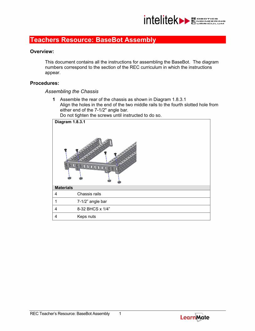
1 Assemble the rear of the chassis as shown in Diagram 1.8.3.1 Align the holes in the end of the two middle rails to the fourth slotted hole from either end of the 7-1/2" angle bar. Do not tighten the screws until instructed to do so.
Diagram 1.8.3.1
Materials 4 Chassis rails
1 7-1/2” angle bar
4 8-32 BHCS x 1/4”
4 Keps nuts
REC Teacher’s Resource: BaseBot Assembly 1
2 Assemble the front of the chassis as shown in Diagram 1.8.3.2. Diagram 1.8.3.2
Materials 1 Rear chassis assembly from step 1
1 Chassis bumper
4 8-32 BHCS x 1/4”
4 Keps nuts
3 Make sure all of the components of the chassis frame are aligned and square, then tighten the hardware.
Assembling the Drive Train Mounting the Motors
Mount the motors to the inside chassis rail as shown in Diagram 1.10.2.1. Tighten the hardware.
Diagram 1.10.2.1
Materials 2 Motor modules
2 Flat Bearings
4 6-32 BHCS x 1/2”
REC Teacher’s Resource: BaseBot Assembly 2
Mounting the Bearings
Mount bearings to the chassis as shown in Diagram 1.10.2.2. Tighten the hardware.
Diagram 1.10.2.2
Materials 6 Flat Bearings
12 8-32 BHCS x 1/2”
12 Keps nuts
REC Teacher’s Resource: BaseBot Assembly 3
Mounting the Gears
Note: Before mounting the gears, be sure the motor mounting screws are tight. Once the gears are installed you will not have access to the top of the motor screws to tighten them.
Mount shafts and gears as shown in Diagram 1.10.2.3.
Do not insert the motor shaft all the way into the motor clutch
Do not tighten the collars until instructed. Diagram 1.10.2.3 A B
Materials 4 36 tooth gears
4 Collars
4 0.318” spacers
2 3” square bars
2 2” square bars
If you cannot fit the spacers between the bearings, proceed to the section “Checking Gear Alignment” below for instructions.
Checking Gear Alignment 1 Rotate the gears by hand and verify that they mesh correctly and do not bind.
If the gears are hard to turn or you cannot fit the spacers in between the bearings:
Loosen the rear end of the associated inside chassis rail.
Slide the inside chassis rail toward the center just enough to allow the gears to rotate freely and then retighten the chassis rail
If the gears move side to side on the shaft:
Slide the inside chassis rail toward the outer rails just enough to keep the gears from sliding.
2 Tighten all the chassis hardware.
REC Teacher’s Resource: BaseBot Assembly 4
Checking Motor Engagement 1 Push the motor shaft into the clutch of the motor.
2 Use the Vex open-ended wrench to rotate the longer shaft . Verify the motor clutch spins with the gears as you turn the long shaft.
3 Tighten the collars on both shafts to secure them in to place.
Mounting the Rear Wheels
Mount the wheels and tighten the collars as shown in Diagram 1.10.2.4 Diagram 1.10.2.4
Materials 2 1.895” hubs with removable tires
2 0.318” spacers
2 Collars
Note: If the portion of the shaft extending from the chassis is too short to mount the collar, loosen the inside collar near the gear and slide the shaft further out.
Once the collar is tightened, verify that the spacer will rotate on the shaft. If the spacer is too tight to rotate:
Loosen the outside collar.
Adjust the wheel to allow more space between the chassis and wheel assembly.
Re-tighten the collar
REC Teacher’s Resource: BaseBot Assembly 5
Mounting the Caster Bearings
Mount the caster bearings as shown in diagram 1.10.2.5. Tighten the hardware. Diagram 1.10.2.5
Materials 2 (2) Flat Bearings
4 (4) 8-32 BHCS x ½”
4 (4) Keps nuts
Mounting the Caster
Mount and align the hub as shown in diagram 1.10.2.6. Diagram 1.10.2.6
Materials 1 5” square bar
1 1.895” hub without removable tires
4 Collars
Tighten the collars to keep the hub centered. The hub should rotate freely without binding.
REC Teacher’s Resource: BaseBot Assembly 6
Mounting the Controller and Battery Shelf 1 Mount the angle bar to the controller as shown in Diagram 1.12.1.1 Diagram 1.12.1.1
Materials 1 Vex controller
1 5” Angle bar
2 8-32 BHCS x ½”
2 Keps nuts
2 Mount the threaded beams and the lower controller bracket to the base of the chassis as shown in Diagram 1.12.1.2 and tighten the mounting screws.
Diagram 1.12.1.2 A B
Materials 4 3” Threaded beams
4 8-32 BHCS x 3/8”
REC Teacher’s Resource: BaseBot Assembly 7
3 Attach the battery shelf to the threaded beams as shown in Diagram 1.2.1.3 and tighten the mounting screws.
Diagram 1.12.1.3
Materials 1 Base plate
4 8-32 BHCS x 1/4”
4 Attach the controller to the battery shelf as shown in Diagram 1.12.1.4. Use the 1/4” screws for the threaded beams and the 3/8” screws for the top of the controller.
Diagram 1.12.1.4 A B
Materials 2 1” Threaded beams
1 2-1/2” Angle bar
2 8-32 BHCS x 3/8”
4 8-32 BHCS x 1/4”
2 Keps nuts
5 Tighten all the mounting hardware.
REC Teacher’s Resource: BaseBot Assembly 8
Installing the Battery 1 Slide the end of each battery strap into its locking mechanism.
2 Mount the battery straps underneath the battery shelf as shown in Diagram 1.12.2.1 and tighten the hardware.
Diagram 1.12.2.1
Materials 1 7.2V robot power pack
2 Reusable battery straps
4 8-32 BHCS x 3/8”
4 Keps nuts
3 Slide the 7.2V Robot power pack through the battery straps underneath the battery shelf. Make sure the battery connector is on the same side as the power switch on the Vex controller.
4 Pull the end of each battery strap to tighten the battery into place.
5 Plug the battery into the controller.
Note: To remove the battery, push in the locking mechanisms and the end of the battery strap.
Connecting the Motors to the Controller 1 Route the wires from each of the motors to the top of the controller.
2 Looking down on the BaseBot, connect the left motor of the BaseBot to the motor port #3 and the right motor to motor port #2.
3 Use cable ties to secure the cables to the BaseBot chassis. This will keep the motor cables safe from entanglement with other robots and gears.
REC Teacher’s Resource: BaseBot Assembly 9
Mounting the Receiver Module 1 Mount the antenna holder, the sleeve and the RF receiver module onto the
chassis and tighten the hardware. Diagram 1.14.1.1 A B
Materials 1 RF receiver module
1 Antenna sleeve and holder
1 Antenna
3 8-32 BHCS x 3/8”
3 Keps nuts
2 Connect one end of the RJ-10 receiver cable to the receiver module and the other end to Rx1 on the Vex controller as shown in the figure below.
REC Teacher’s Resource: BaseBot Assembly 10
Installing the Frequency Crystals
Caution: Be sure you have multiple frequencies available in the classroom. Be aware of which frequency you use so that you do not conflict with the frequencies of those around you.
Using the same frequency for more the one robot can be dangerous.
If you do not have multiple frequency channels available or if you encounter conflicting frequency channels, you must use a tether to operate your robot
1 Ask your teacher for the proper frequency to use in your BaseBot .
2 Carefully insert the frequency module into the transmitter as shown in the figure below.
Caution: Do not force the frequency crystals in place or you may bend or break the pins on the crystals.
3 Carefully insert the frequency crystal into the receiver as shown in the figure below.
4 Verify that the frequency channels are the same for both of your crystals.
REC Teacher’s Resource: BaseBot Assembly 11
Installing the Transmitter Battery 1 Remove the battery cover from the rear of the transmitter.
2 Install the 9.6V transmitter battery into the rear of the controller.
3 Verify that the battery connection locks together.
4 Replace the battery cover. (Be careful not to pinch the battery wires.)
5 Slide the power switch on the front of the transmitter into the ON position.
The transmitter’s battery voltage will be displayed on the transmitter’s LCD screen. If the battery’s voltage is 8.9V or less, it is time to recharge the transmitter’s battery.
6 Extend the antenna of the transmitter.
Testing the BaseBot
Caution: Always lift the robot so that the drive wheels are off the ground before turning the power on. This will reduce the risk of an accident from unexpected movement.
1 Slide the power switch on the Vex controller to the ON position.
Note: The battery power light on the front of the controller should be green indicating a properly charged battery. If the light is red, recharge the 7.2V robot power pack.
2 Place the BaseBot on the ground.
3 Push the left joystick up (channel 3). The left side of the BaseBot moves forward.
4 Push the right joystick up (channel 2). The right side of the BaseBot moves forward.
If either of side of your robot does not respond to the transmitter, review all the wiring connections to make sure everything is correct.
Once you verify that both sides are responding to the input of the transmitter:
5 Push both joysticks up and verify that the robot moves forward.
6 Push both joysticks down to move the robot backwards.
7 Push one joystick up and the other down in order to turn the robot.


![SPECIALISTS IN SUPPLY OF BATTERIES TO THE HEALTHCARE …esbicomedical.com/images/Medical Batteries Catalogue.pdf · 2014. 5. 7. · GW Pump [1000EL00349] 7.2v./1.25Ah 02161 Original](https://static.documents.pub/doc/80x56/60b2254e518c330ffc06bc3e/specialists-in-supply-of-batteries-to-the-healthcare-batteries-cataloguepdf-2014.jpg)


