P.T. ATMINDO-MEDAN page 1 SPECIFICATION FOR STEAM BOILER PLANT SFMW 20-SH-VG-ECO Manufactured by P.T. ATMINDO-MEDAN Attachment to Our Quotation No.100-Q-xxx/10 TECHNICAL MAIN DATA: Boiler Type................................SFMW 20-SH Grate................................VibroGrate VG-20 Maximum Continuous Rating (MCR)................20 t/h Design Pressure..........................46.5 bar (g) Steam Pressure at Superheater Outlet.......42 bar (g) Steam Temperature at Superheater Outlet.......435 0 C Feed Water Temperature........................105 0 C Guarantee Fuel (100%)..................Coal (lignite) MARSIMAX ADITYA RAJA DERADJAT 0818.062.22.062
* Acid capacity – KS 8.2 (previously pH value),E.g. KS 8.2 1 m mole = previously pH value 1 mval/l
Blow-down during approval test is closed.
1.1.4 COMBUSTION
Reference O2 volume, dry 4.9 %
1.1.5 AIR
Reference temperature for efficiency : 25 0CSuction temperature, design : 40 0C
1.1.6 CIVIL WORK
Atmindo shall provide the foundation drawings.
The client handed over the soil investigation report and plant layout to Atmindo.
MARSIMAX ADITYA RAJA DERADJAT
0818.062.22.062
P.T. ATMINDO-MEDAN page 8
The figures marked “G” are guaranteed values. All the other values are to be considered as approximate values, which may change slightly after detailed design of the plant:
1.2 CAPACITY DATA
Fuel : Bukit AsamWater content : 25 % guar.Maximum Continuous Rating (MCR) : 20 T/h SH “G”Design pressure : 46.5 bar (g) “G“Steam pressure at boiler outlet, MCR : 42 bar (g) “G“Steam temperature at boiler outlet, MCR : 435 0 C “G“Feed water temperature : 105 0CFlue gas temperature at boiler outlet, app. : 180 0 C
Quantity of fuel required : 3120 kg/hrQuantity of fuel combusted : 3060 kg/hrExcess Air : 1.5Combustion air quantity, MCR : 27310 Nm3/hrFlue gas quantity, MCR : 29400 Nm3/hr
1.3 TESTS
Any tests carried out to prove the guaranteed steam capacities and efficiency shall be effectuated - if requested - according to the standards of the Verein Deutsche Ingenieure, DIN 1942, at your expense; they refer to the lower heating value of the indicated fuel.
Among others: Blow down is closed
1.4 EMISSION
Particulars, Eref : 350 mg/m3 Ref. O2 % in dry volume : 10 %Ref. volume at : 1 bar, 25 0C
Formula for correction:
MARSIMAX ADITYA RAJA DERADJAT
0818.062.22.062
2 GUARANTEED AND APPROXIMATE VALUES
P.T. ATMINDO-MEDAN page 9
Eref = the particular demand (here 350 mg/m3)O2 % ref = the related volume oxygen content of demand (here 10 %)O2 % measured = the measured dry volume oxygen.E measured = the measured mass of particulars
Other emission demandsNO2 (nitrogen dioxide) : 850 mg/m3
With regard to material quality design and workmanship, we assume guarantee for a period of 12 months after start-up, but limited to 15 months after completion of erection.
MARSIMAX ADITYA RAJA DERADJAT
0818.062.22.062
P.T. ATMINDO-MEDAN page 10
The specification refers to one unit boiler except otherwise stated.
1.6 FUEL SYSTEM
A belt conveyor (client’s scope) with profiled belt elevates the fuel up to the dividing chute over the daily bunker silo. The bunker silo is designed for approximately one day of fuel consumption. With one chute the coal rest on the below screw feeder and the speed is inverter controlled based upon the pressure in the drum. The very spreading of the fuel is executed by the pneumatic spreader.
1.7 COMBUSTION SYSTEM
The water-cooled VibroGrate® will be installed with a declining angle of 7.0 0 towards the boiler front.
The slag removal will be achieved by vibrating the grate. The slag moves to the lower part of the grate and leaves downwards to the slag remover below The stoker doors are side hinged and air cooled and acts mainly as access doors to the grate.
The primary air enters the furnace through holes distributed over the total grate area.
For a better swirling of the flue gases in the furnace and for a better combustion of the suspended fuel particles, secondary air nozzles are provided on the boiler front and rear wall.
The secondary air is blown into the furnace at a high speed through these nozzles. Manual operated dampers can control the air quantities. For boosting the secondary air pressure a separate fan is provided.
A biogas burner (delivered by the client) shall be installed in the furnace and most obvious in the side wall.
1.8 BOILER PRESSURE SYSTEM
The boiler offered by us is part of a series, which we have developed especially for the firing of solid fuel.
The boiler is designed according to DIN/TRD and is approved by the relevant Indonesian authorities, i.e. DEPNAKER which at the same time is supervising the manufacturing, erection and commissioning of the boiler.
MARSIMAX ADITYA RAJA DERADJAT
0818.062.22.062
3 DESCRIPTION OF THE BOILER PLANT
P.T. ATMINDO-MEDAN page 11
Therefore, we are able to present a number of reference plants of the same order of magnitude, which we should like to show to you.
On the basis of the performance data indicated by you, we have suggested a radiant boiler of the 3-pass type with longitudinal arranged upper and lower drum featuring membrane walls and water-cooled grate, as well an economizer to increase the efficiency.
The bottom headers are supplied with interconnecting pipes from the lower drum. The down comers are not exposed to heat and thus, a satisfactory water circulation in the boiler is guaranteed.
The combustion chamber is sufficiently dimensioned, that the fuel fired is burnt to a possible maximum before entering the convection-heating surface. The evaporator banks, which can easily be inspected via sufficiently large inspection lanes, are arranged in the second and third boiler passes.
Fly ash collecting hoppers are arranged below the radiation chamber, second and third passes. Dampers will affect the fly ash discharge.
The total boiler is of the gas tight type; thus, air infiltration is minimized.
A sufficient number of inspection and observation openings are provided.
Due to the chosen type of boiler construction, a large water volume is available which takes high load variations into account.
A superheater of the horizontal type is arranged in the second pass of the boiler. The saturated steam to be superheated is extracted from the upper drum and passed to the superheater through a collecting pipe. The superheater is provided with a safety system consisting of a no. of thermocouples reg. the temperature on the SH surface. At too high temperature the signal opens the start valve to ensure steam flow if the steam turbine trips or the flow stops of other reasons.Special drum internals ensure a good steam quality.
The upper drum with 1 manhole closure, the internals for steam drying, the feed water distribution pipe, the blow down pipe, the necessary sockets and valve connecting branches are electric welded.
The lower drum with 1 manhole closure, the necessary studs and supports, down comers for the evaporator system are electric welded.
The furnace and radiation chamber walls are arranged as evaporator system with the evaporator tubes as membrane walls.The other boiler walls are likewise membrane walls.
Evaporator banks with the steam generating tubes are situated in the 2 and the 3 pass.
The buck stays including necessary brackets for fixing to the membrane walls.
MARSIMAX ADITYA RAJA DERADJAT
0818.062.22.062
P.T. ATMINDO-MEDAN page 12
Internal boiler piping for evaporator as well as boiler drain and vent piping including the necessary fittings and supporting materials.
Outside the boiler an ECO is connected bringing the flue gas temperature down to a reasonable level in respect of the sulphur content.
1.9 SOOT BLOWER SYSTEM
The cleaning system is chosen as a steam soot blowing system, manual operated
For the economizer steam soot blowers are chosen and manual operated.
1.10 COMBUSTION AIR SYSTEM
For this type of boiler we have shown most care to the combustion. This consists of fuel in a hot atmosphere and added air. The air is distributed by use of nozzles located in three rows. By that, we ensure good swirling in the furnace, and make it easier for the fuel to find air. The combustion becomes more efficient, and this means higher efficiency of the introduced fuel.The system is controlled automatic. By automatic means, the operator do not need to adjust the air flow, as a smoke density meter measures the smoke density content continuously in the flue gas and the air amount to the boiler/furnace by opening and closing the guide vane for the Total Air Fan (TAF) becomes following adjusted to match the set value. A part of the air is primary air for the three combustion air zones below the grate. The air can be trimmed by manual dampers, one for each zone. Each nozzle row is provided with trim dampers to manipulate the air share above the grate. Below the grate each lane (spreader) also becomes adjusted by dampers and the pressure can be observed on pressure indicators.
1.11 FLUEGAS SYSTEM
The dust loaded flue gases passes to a multi cyclone dust collector where the dust is separated to a large extent. But through the full length of the boiler fly ash will constant become segregated.
An induced draught fan is provided with a guide vane for ensuring sufficient under pressure in the furnace and for discharge of the flue gases to the chimney. The guide vane is automatic operated.
An environment measuring platform is attached the chimney in the correct level.Chimney with platform for isokinetic measurement according to US EPA method 5.
MARSIMAX ADITYA RAJA DERADJAT
0818.062.22.062
P.T. ATMINDO-MEDAN page 13
The suggested arrangement is shown in the enclosed boiler plant lay out drawing.
1.12 ASH SYSTEM
Across the radiation room, there is a screw conveyor continually removing the segregated coarse ash from the flue gas.
4 rotary valves are situated below the 2. and 3. pass, leaving the segregated ash to the lower screw conveyor.
Below the dust collector the ash is always automatic discharged.Riddling below the grate has to be removed occasionally, depending on firing and behaviour of the vibrating grate.
1.13 SLAG SYSTEM
The use of the VibroGrate system frequently removes the ash from the grate to a dry slag remover. Three stoker doors give access for inspection of the combustion. Watch frequently the combustion to achieve the best result. The slag passes a clinker crusher and becomes transported in screw conveyors to the slag mill.
1.14 FEED WATER SYSTEM
Feed water pumps for one (1) boiler shall be provided, each capable to deliver feed water in excess (125 %) of the normal capacity of the boiler. Each pump is to be protected by a relief valve ensuring sufficient cooling of the pump in case the feed water control valve closes. In this case, the drives are two motors.
1.15 EXTERNAL PIPE SYSTEMS
N/A
1.16 INSULATION & SURFACE TREATMENT
The boiler, economizer and ducts are insulated to a necessary level to ensure low cooling from convection.
1.17 PLATFORMS & STAIRS
For inspection of the boiler is provided with four platforms connected by stairs. One platform is for the feed water tank and one for the economizer.
MARSIMAX ADITYA RAJA DERADJAT
0818.062.22.062
P.T. ATMINDO-MEDAN page 14
1.18 POWER SYSTEM
The electrical equipment includes a low-voltage distribution panel BUSBAR system with 240/380 V, 50 Hz for the boiler.
The breaker devices necessary for the boiler consumers as well as interlock, controls and alarm system are installed in a freestanding cabinet in the vicinity of the boiler.
The boiler MCC is for in-door use and dust proof type, equipped with incoming feeder components and outgoing feeder components.
1.19 CONTROL & INSTRUMENTATION SYSTEMS, C & I
The offered measuring and control equipment corresponds to a full controlled level arranged according to our experience. It contains all measuring and controls elements required for operation of the boiler. Water, combustion air, fuel and finally furnace pressure control.
Remote water level indication is included and installed in boiler.For the feed water flow control, we have provided a motorized control valve, which opens or closes in accordance with the water level in the upper drum.
The air amount is controlled by analysing the flue gas for oxygen.
Fuel feeding is controlled by the drum pressure is also a feature in the MCC as well.
The under pressure is controlled by the furnace pressure.
Local instruments installed at the boiler front remotely indicating the measuring quantities necessary for monitoring of the boiler operation.
1.20 FLUEGAS CLEANING SYSTEM
For reducing the amount of dust to the surroundings, the flue gas becomes reduced for particulars by a multi cyclone.
1.21 CIVIL WORK
Atmindo deliver drawings made in accordance to the need of foundations for the scope and based on the client’s soil investigation report and plant layout.
1.22 SPECIAL TOOLS
N/A as the tools for maintenance is all standard products in the market
MARSIMAX ADITYA RAJA DERADJAT
0818.062.22.062
P.T. ATMINDO-MEDAN page 15
1.23 ERECTION & COMMISSIONING
1.23.1 ERECTION
The boiler will be prefabricated in our workshop to the largest possible extent in the work shop, paying special attention to the local means of transportation.
The largest component to be transported is the upper drum with:
Overall length : 8150 mm
Outside diameter : 1200 mm
Total weight : 10000 kg
The erection time at site is shortened considerably due to prefabrication in our workshop.
For performance and supervision of erection, an experienced erection specialist will be at your disposal assisted and sufficient number of skilled personnel is included the scope. The erection sequence will be agreed upon and coordinated with you.
You should provide correspondingly qualified operation personnel even before completion of erection and during start up. During that period, your personnel will be trained by us with regard to its future task and familiarized with the specific features of the boiler.
It is assumed that the erection works will be executed in a roofed boiler house.
1.23.2 COMMISSIONING
Correspondingly, you shall provide qualified operation personnel even before completion of erection and during start up. During that period your personnel will be trained by us with regard to its future task and familiarized with the specific features of the boiler.
Final approval test takes place right after trim of boiler, if trim is necessary.The staffs take over after final approval test.Take-over takes place right after final approval test.
1.23.3 STATUTORY APPROVALS
Obtaining and arranging for all approvals, licensee’s certification and test needed from or provided by the relevant Indonesian authorities with regard to the manufacturing, erection, testing and commissioning of the boiler.
MARSIMAX ADITYA RAJA DERADJAT
0818.062.22.062
P.T. ATMINDO-MEDAN page 16
1.24 FUEL SYSTEM
1 off split chute1 off daily bunker silo1 off Screw Reclaimer1 off Coal Feeder3 off Pneumatic spreader units
1.25 COMBUSTION SYSTEM
1 off water-cooled VibroGrate® with support and unbalanced motors
1.26 BOILER PRESSURE SYSTEM
1 off Economizer1 off horizontal 2 drums steam boiler with furnace and radiation room in 1. pass.
Consisting of1 set off gastight welded membrane wall all over3 off steam generating banks (1 in 2nd pass and 2 in 3rd pass)1 off superheater, heat overload protected, in 2nd pass1 set off silencer (1 for SH and 2 for Drums)
BOILER SUPPORTING STRUCTURE
1 off frame type to sustain the loads resulting from the boiler and pipe work
BOILER ASSESSORIES
4 off access doors and observation holes2 off peepholes1 set off valves and fittings (see valve list)1 off chemical dosing plant
MISC. BOILER PIPE SYSTEMS
1 off blow down vessel from mild steel1 set off drain pipes to the blow down vessel1 off sample cooler for feed water, boiler water and steam1 off system support
MARSIMAX ADITYA RAJA DERADJAT
0818.062.22.062
4 SCOPE OF SUPPLY
P.T. ATMINDO-MEDAN page 17
1.27 SOOT BLOWER SYSTEM
1.27.1 BOILER
6 off steam soot blowers including wall box1 set off pipes, valves and fittings
1.27.2 ECONOMIZER
2 off multi nozzle soot blower, manual1 off pipes, valves and fittings
1.28 COMBUSTION AIR SYSTEM
TOTAL AIR FAN (TAF)
1 off single inlet, overhung type1 off V-belt drive1 off base frame, steel1 off three-phase squirrel-cage motor1 off Guide vane, actuator operated1 set off air duct system between fan and firing system3 off trim dampers below grate
SECONDARY AIR FAN (SAF)
1 off single inlet, overhung type1 off V-belt drive1 off base frame, steel1 off three-phase squirrel-cage motor1 off damper, manual operated1 set off air duct system between fan and firing system2 off trim dampers for 2 nozzles rows
CARRIER AIR FAN (CAF)
1 off single inlet, overhung type1 off direct drive1 off base frame, steel1 off three-phase squirrel-cage motor1 set off air duct system between fan and firing system2 off trim dampers for 2 spreaders
MARSIMAX ADITYA RAJA DERADJAT
0818.062.22.062
P.T. ATMINDO-MEDAN page 18
1.29 FLUE GAS SYSTEM
INDUCED DRAUGHT FAN (IDF)
1 off single inlet, overhung type on steel1 off V-belt drive with fluid coupling1 off base frame, steel1 off three-phase squirrel-cage motor with surface cooling and anti-friction bearings1 off guide vane, actuator operated2 off flexible connections, inlet and outlet1 set off flue gas ducts system between boiler outlet and the chimney
CHIMNEY
1 off single shell chimney incl. anchor bolt system (embedded) 1 off measurement platform1 off access ladder to the platform1 off lightning system
1.30 ASH SYSTEM
4 off rotary valves, 2. and 3. pass1 off screw conveyor, pass 2 and 31 off screw conveyor, radiation chamber
1.31 SLAG SYSTEM
3 off slag doors (equal to the no. of spreaders)1 off slag hopper below the VibroGrate outlet1 off slag screw conveyor1 off clinker crusher1 off transport conveyor1 off slag mill
1.32 FEED WATER SYSTEM
2 off centrifugal feed pump for direct coupling to drive1 off chemical dosing system2 off three-phase squirrel-cage motor2 off flexible couplings with guard
Each set on common base frame for each pump and drive set
PIPE LINE SYSTEM
1 set off feed water downcomer pipes
MARSIMAX ADITYA RAJA DERADJAT
0818.062.22.062
P.T. ATMINDO-MEDAN page 19
1 set off discharge piping from the feed water pumps to the boiler
Following valves are included for the feed water pump station
2 off Relief valves2 off Non-return valves2 off strainers4 off Shut-off valves
1.33 EXTERNAL PIPE SYSTEMS
N/A
1.34 INSULATION AND SURFACE TREATMENT
INSULATION
1 set off insulation with cladding
SURFACE TREATMENT
1 off Paint for cold surface components with a surface temp. up to 100 0 C
1 off Paint for hot surface components with a surface temp. up to 400 0 C
1.35 PLATFORMS AND STAIRS
1 set off platforms and stairs for the boiler to provide sufficient access for operation and observation of the boiler (see boiler plant lay out), ECO and daily fuel silo
1.36 POWER SYSTEM
LOW – VOLTAGE DISTRIBUTION PANEL
With BUSBAR system, with built-in contactors, fuses, relays, signal lamps, load break switches for the consumers all in a power and control panel.
1 for screw fuel reclaimer INV1 for fuel screw feeder DOL1 for unbalanced motors DOL1 for total air fan S/S1 for secondary air fan S/D1 for carrier air fan DOL1 for induced draft fan S/S1 for slag conveyor DOL1 for clinker crusher DOL
MARSIMAX ADITYA RAJA DERADJAT
0818.062.22.062
P.T. ATMINDO-MEDAN page 20
1 for coarse ash conveyor DOL6 for ash rotary valves DOL2 for slag/ash screw conveyors DOL2 for feed water pump S/S
INSTALLATION MATERIAL:
1 set off cables incl. cable to shell feeder1 set off cable trays and ladders
1.37 CONTROL & INSTRUMENTATION SYSTEM, C & I
1 off Basic engineering, I/O cards for S7 via bus signal to marshalling rack. 1 set off Cabling to marshalling rack is included.
1 set off local instruments, standard scope (see instrument list)
Control loops / remote indicator as:
1 off 3-element water level control, boiler LICHAL1 off fuel feed control, inverter SIC1 off combustion air control, QIC1 off furnace pressure control PIC
INSTALLATION MATERIAL:
1 set off signal cables1 set off cable trays and ladders
1.38 FLUEGAS CLEANING SYSTEM
N/A
1.39 CIVIL WORK
1 set off drawings for the scope of supply will be provided, based upon the soil investigation report from the client for the site
1.40 SPECIAL TOOLS
N/A as all necessary tools is standard
MARSIMAX ADITYA RAJA DERADJAT
0818.062.22.062
P.T. ATMINDO-MEDAN page 21
1.41 ERECTION AND COMMISSIONING
1.41.1 ERECTION
The complete erection of the offered scope of supply is included all skilled and unskilled labours as well as a responsible erection supervisor. It is assumed that erection takes place in a roofed boiler house.
1.41.2 COMMISSIONING
Correspondingly, you shall provide qualified operation personnel even before completion of erection and during start up. During that period, your personnel will be trained by us with regard to its future task and familiarized with the specific features of the boiler.
Final approval test takes place right after trim of boiler, if trim is necessary.The staffs take over after final approval testTake-over takes place right after final approval test.
1.41.3 STATUTORY APPROVALS
Obtaining and arranging for all approvals, licensee’s certification and test needed from or provided by the relevant Indonesian authorities with regard to the manufacturing, erection, testing and commissioning of the boiler.
MARSIMAX ADITYA RAJA DERADJAT
0818.062.22.062
P.T. ATMINDO-MEDAN page 22
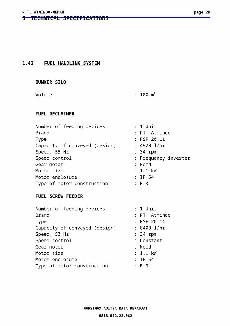
1.42 FUEL HANDLING SYSTEM
BUNKER SILO
Volume : 100 m3
FUEL RECLAIMER
Number of feeding devices : 1 UnitBrand : PT. AtmindoType : FSF 20.11Capacity of conveyed (design) : 4920 l/hrSpeed, 55 Hz : 34 rpmSpeed control : Frequency inverterGear motor : NordMotor size : 1.1 kWMotor enclosure : IP 54Type of motor construction : B 3
FUEL SCREW FEEDER
Number of feeding devices : 1 UnitBrand : PT. AtmindoType : FSF 20.14Capacity of conveyed (design) : 8400 l/hrSpeed, 50 Hz : 34 rpmSpeed control : ConstantGear motor : NordMotor size : 1.1 kWMotor enclosure : IP 54Type of motor construction : B 3
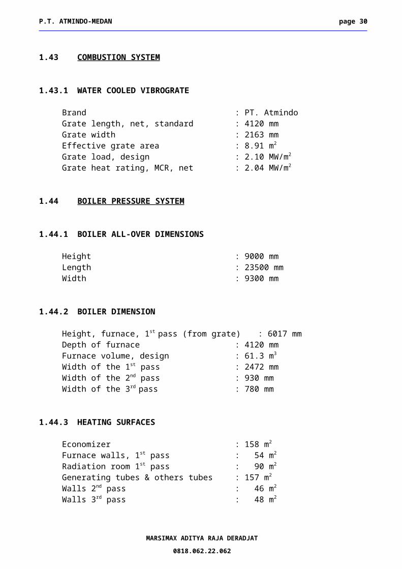
1.43 COMBUSTION SYSTEM
1.43.1 WATER COOLED VIBROGRATE
Brand : PT. AtmindoGrate length, net, standard : 4120 mmGrate width : 2163 mm Effective grate area : 8.91 m2 Grate load, design : 2.10 MW/m2
Width of the 1st pass : 2472 mmWidth of the 2nd pass : 930 mmWidth of the 3rd pass : 780 mm
1.44.3 HEATING SURFACES
Economizer : 158 m2
Furnace walls, 1st pass : 54 m2
Radiation room 1st pass : 90 m2
Generating tubes & others tubes : 157 m2
Walls 2nd pass : 46 m2
Walls 3rd pass : 48 m2
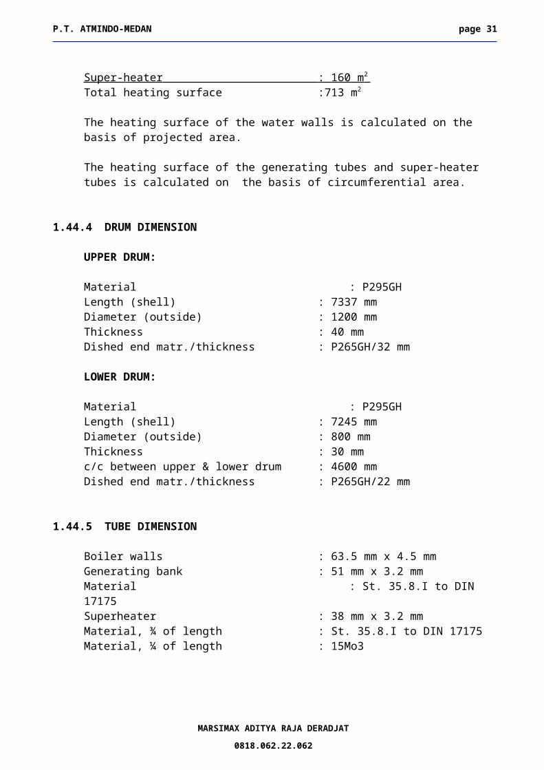
Super-heater : 160 m 2 Total heating surface :713 m2
The heating surface of the water walls is calculated on the basis of projected area.
The heating surface of the generating tubes and super-heater tubes is calculated on the basis of circumferential area.
1.44.4 DRUM DIMENSION
UPPER DRUM:
Material : P295GHLength (shell) : 7337 mmDiameter (outside) : 1200 mmThickness : 40 mmDished end matr./thickness : P265GH/32 mm
MARSIMAX ADITYA RAJA DERADJAT
0818.062.22.062
P.T. ATMINDO-MEDAN page 24
LOWER DRUM:
Material : P295GHLength (shell) : 7245 mmDiameter (outside) : 800 mm Thickness : 30 mmc/c between upper & lower drum : 4600 mmDished end matr./thickness : P265GH/22 mm
1.44.5 TUBE DIMENSION
Boiler walls : 63.5 mm x 4.5 mmGenerating bank : 51 mm x 3.2 mmMaterial : St. 35.8.I to DIN 17175Superheater : 38 mm x 3.2 mmMaterial, ¾ of length : St. 35.8.I to DIN 17175Material, ¼ of length : 15Mo3
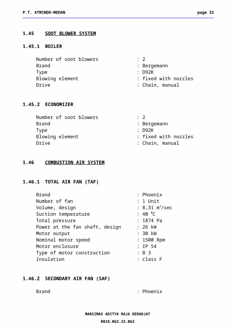
1.45 SOOT BLOWER SYSTEM
1.45.1 BOILER
Number of soot blowers : 2Brand : BergemannType : D92KBlowing element : fixed with nozzlesDrive : Chain, manual
1.45.2 ECONOMIZER
Number of soot blowers : 2Brand : BergemannType : D92KBlowing element : fixed with nozzlesDrive : Chain, manual
1.46 COMBUSTION AIR SYSTEM
1.46.1 TOTAL AIR FAN (TAF)
Brand : PhoenixNumber of fan : 1 UnitVolume, design : 8,31 m3/sec Suction temperature : 40 0C Total pressure : 1874 Pa
MARSIMAX ADITYA RAJA DERADJAT
0818.062.22.062
P.T. ATMINDO-MEDAN page 25
Power at the fan shaft, design : 26 kWMotor output : 30 kWNominal motor speed : 1500 Rpm Motor enclosure : IP 54 Type of motor construction : B 3Insulation : class F
1.46.2 SECONDARY AIR FAN (SAF)
Brand : PhoenixNumber of fan : 1 Unit Volume, design : 2.28 m3/sec Suction temperature : 40 0C Total pressure : 3074 PaPower at the fan shaft, design : 11.7 kW Motor output : 18.5 kW Nominal motor speed : 1500 Rpm Motor enclosure : IP 54 Type of motor construction : B 3Insulation : class F
1.46.3 CARRIER AIR FAN (CAF)
Brand : PhoenixNumber of fan : 1 Unit Volume, design : 0,15 m3/sec Suction temperature : 40 0C Total pressure, design : 3749 PaPower at the fan shaft, design : 1.1 kW Motor output : 5,5 kW Nominal motor speed : 3000 Rpm Motor enclosure : IP 54 Type of motor construction : B 3Insulation : class F
1.47 FLUEGAS SYSTEM
1.47.1 INDUCED DRAUGHT FAN (IDF)
Brand : PhoenixVolume, design : 13.47 m3/secSuction temperature : 180 0CTotal pressure, design : 1275 PaPower at the fan shaft, design : 55.7 kWFan speed : < 1000 rpm
MARSIMAX ADITYA RAJA DERADJAT
0818.062.22.062
P.T. ATMINDO-MEDAN page 26
Motor output : 75 kWNominal motor speed : 1.500 RpmMotor enclosure : IP 54Type of motor construction : B 3Insulation : class F
1.47.2 CHIMNEY
Type : Single shellHeight : 24 m in 4 partsDiameter : 1 mThickness, shell plate, max : 9-6-6-4.5 mmWind load, max : 25 m/sObservation platform : Ring segment platform w. railing
in acc. to ISERA rulesConnection : Ladder with safety guard
1.48 ASH SYSTEM
RACHABrand : PTAType : screw conveyorNumber of : 1Diameter : 270 mmGear motor brand : NordMotor size : 1.5 kW
PASSESBrand : PTAType : Screw conveyorNumber of : 1Diameter : 270 mmGear motor brand : NordMotor size :1.5 kW
Type : screw conveyorDiameter : 330 mmGear motor brand : NordSpeed : 33Motor size : 1.5
1.50 FEED WATER SYSTEM
1.50.1 FEED WATER PUMP
Brand : SIHICapacity, design, case 4 : 26 t/hPump discharge pressure, case 4 : 48.7 bar (g)Speed : 2.940 RpmPower requirement at the shaft, case 4 : 60 kW
1.50.2 MOTOR DRIVE
Brand: Teco
Motor size : 75 kWSpeed : 2900 rpmMotor enclosure : IP 54Construction : B3
1.51 EXTERNAL PIPE SYSTEMS
N/A
MARSIMAX ADITYA RAJA DERADJAT
0818.062.22.062
P.T. ATMINDO-MEDAN page 28
1.52 INSULATION & SURFACE TREATMENT
INSULATION
Insulation material : Rock woolThickness : 100 mmCladding, boiler body : 0.8 mm galvanizedCladding for drums and headers : 0.8 mm aluminiumInsulation for pipes depends on the diameter and temperatureCladding, pipes : 0.7 mm aluminium
SURFACE TREATMENT
For cold surface components with a surface temperature up to 100 0 C
Mechanical cleaning and degreasingPrimary Coat by Hempel primer paint or equivalentTop coat by Alkyd enamel or equivalent
For hot surface components with a surface temperature up to 400 0 C
Sand blastingPrimary coat by Heat resistant paintTop Coat by Heat resistant paint
Voltage : 3x400 V ACVoltage : 1x230 V ACVoltage : 1x48 V ACVoltage : 1x24 V DCFrequency : 50 Hz
Lightning system for chimney Lightning arrestor of max 1 Ohm
1.55 CONTROL & INSTRUMENTATION
Standard in accordance to instrument list
Control as described in scope of supply
MARSIMAX ADITYA RAJA DERADJAT
0818.062.22.062
P.T. ATMINDO-MEDAN page 29
Specification in acc. to instrument list
1.56 FLUEGAS CLEANING SYSTEM
1.56.1 MULTI CYCLONE (N/A)
Brand :No of cones :Material, cones : Flue gas flow, design :temperature, max. : Flue gas temperature, normal : Dust load in the clean gas :Average collector efficiency : Pressure drop at MCR :
1.57 CIVIL WORK
1 set off drawings for the scope of supply will be provided, based upon the geodetic report from the client for the site
MARSIMAX ADITYA RAJA DERADJAT
0818.062.22.062
P.T. ATMINDO-MEDAN page 30
BEGINNING from ENDING
Feed water:Flange on valve before feed pump within supply
Chemical dosingWithin supply Nozzle on FW down comer
and feed water pipeLife steam:Within supply after MSV
Blow off pipe of savety valve
Back pressure steam:N/A
Condensate:N/A
Make up waterN/A
Sample cooler:Within supply Sample cooler outlet
Drain:Within supply Blow down vessel
Vents:Within supply Vent pipe outlet
Blow down:Within supply Outlet, blow down tank
Fuel:Split chute, bunker silo within supply
Combustion air:Air intake of fans within supply
Flue gas:Within supply Chimney outlet
Slag:Within supply Outlet, slag mill
MARSIMAX ADITYA RAJA DERADJAT
0818.062.22.062
6 LIMITS OF SUPPLY
P.T. ATMINDO-MEDAN page 31
Fly ash:Within supply Outlet, slag mill
Power:Terminal point, ingoing, MCC within supply
Signals:Terminal point, ingoing, Marshalling rack Within supply
1.58 OUR OFFER DOES NOT INCLUDE (OUT OF SCOPE)
Incoming power cable to MCC
External signals to cubicle
Fuel conveyor system before daily bunker silo
External piping except expressly mentioned
Water treatment plant, make up water tank and deaerator
Earth wire system and lightning conductor system others than specified
Red Lighting on the chimney
Lighting on boiler
Ash and slag removal systems other than specified
Feed water system , before boiler feed pump
Consumables: Fuel, water, chemicals for erection, hydro-test and commissioning until
take over except boil out chemicals and 1. filling of lubrication oil and grease
Pipe between blow down tank (flash tank) & blow down pit, if any


![N VG [ U{FZJ VG]EJLV[ KLV[P - Gujarat · N VG [ U{FZJ VG]EJLV[ KLV[P - Gujarat ... s], - - - - 5](https://static.documents.pub/doc/80x56/5e13200df3ca9032df67634a/n-vg-ufzj-vgejlv-klvp-gujarat-n-vg-ufzj-vgejlv-klvp-gujarat-.jpg)


