46
TECHLINE HCVXR AND CV DESIGN GUIDE DRIPLINE FOR SUBSURFACE AND ON-SURFACE
LTLCVDG 11/16
NETAFIM USA5470 E. HOME AVE.FRESNO, CA 93727CS 888 638 2346www.netafimusa.com
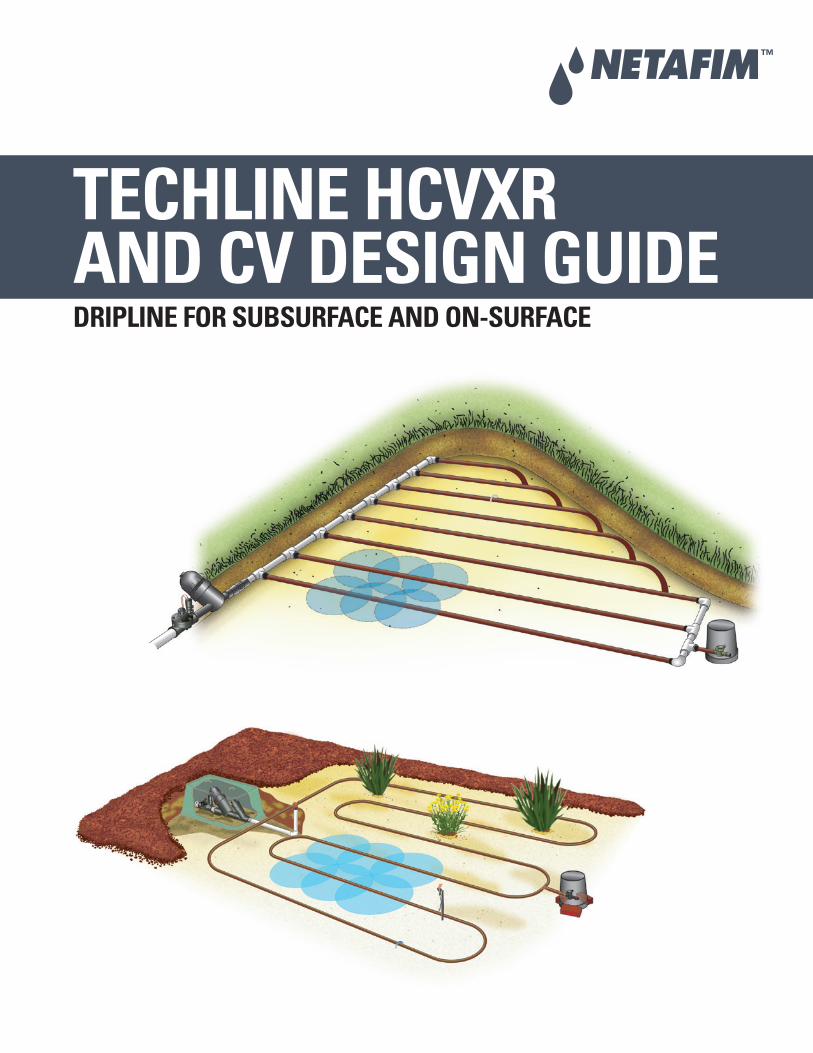
TECHLINE HCVXRAND CV DESIGN GUIDEDRIPLINE FOR SUBSURFACE AND ON-SURFACE
1
N E T A F I M T E C H L I N E® H C V X R a n d C V D E S I G N G U I D E
TABLE OFCONTENTS
INTRODUCTIONOverview.......................................................................................................................................3
DESIGN CRITERIASite Survey ...................................................................................................................................4Point of Connection ....................................................................................................................4
BASIC DESIGN STEPSWhen Should You Use Techline HCVXR or CV .......................................................................5Choosing the Proper Techline HCVXR or CV ..........................................................................5General Guidelines Charts.........................................................................................................6Types of Layouts ..........................................................................................................................7What Do These Layouts Have in Common? ...........................................................................7GRID Layout .................................................................................................................................7LITE Layout ...................................................................................................................................8Calculating Equal Row Spacing ...............................................................................................8Length of Techline Rows ............................................................................................................9 Maximum Length of Laterals Charts ........................................................................................9Center Feed GRID Layout.........................................................................................................10 Other GRID Layout Considerations ........................................................................................10Creating Sub-Headers to Reduce Glue/Saddle Joints .......................................................11Zone Water Requirements ......................................................................................................11Flow Per 100' Charts .................................................................................................................11Calculating Total Zone Water Demand..................................................................................12Fittings.........................................................................................................................................13Staples ........................................................................................................................................14Line Flushing Valves .................................................................................................................14If An Automatic Flush Valve is Not Desired ..........................................................................14If An Air/Vacuum Relief Vent is Desired ................................................................................15Filters...........................................................................................................................................16Disc Filter Sizing Charts ...........................................................................................................16Pressure Regulating Valves (PRV) .........................................................................................17Pressure Regulator Sizing Charts ..........................................................................................18Low Volume Control Zone Kits - Disc ....................................................................................19Low Volume Control Zone Kits - Screen ...............................................................................20Slopes and Berms .....................................................................................................................21In-Line Check Valve ..................................................................................................................21Trees ............................................................................................................................................22Pressure and Flow Checks ......................................................................................................22Calculating Precipitation Rates ..............................................................................................22
2
N E T A F I M T E C H L I N E® H C V X R a n d C V D E S I G N G U I D E
TABLE OFCONTENTS(CONTINUED)
TECHLINE HCVXR AND CV IN TURFTurfgrass .....................................................................................................................................23Where and Why to Use Techline in Turf ...............................................................................23Tips for Using Techline in a Newly-Sodded Lawn ...............................................................24
SPECIAL APPLICATIONS AND TIPSParking Lot Islands ...................................................................................................................25Electrical Grounding .................................................................................................................25Above and Below Grade ..........................................................................................................25
WINTERIZING INSTRUCTIONSWinterizing Instructions...........................................................................................................26Manual Winterization ...............................................................................................................26Compressed Air Winterization ................................................................................................26
TECHNICAL DATATechline HCVXR Dripline ..........................................................................................................27Techline CV Dripline .................................................................................................................28Techline CV and Techline HCVXR Emitters ...........................................................................29Design Formulas........................................................................................................................30Specifying Model Numbers.....................................................................................................32Techline HCVXR Application Rate Tables .............................................................................33Techline CV Application Rate Tables .....................................................................................34End Feed Layout ........................................................................................................................35Slope Layout ..............................................................................................................................36Block System on Slope Layout ...............................................................................................37Center Feed Layout ...................................................................................................................38Installation Checklist ................................................................................................................39System Inspection Checklist ...................................................................................................40Friction Loss Charts ..................................................................................................................41
3
N E T A F I M T E C H L I N E® H C V X R a n d C V D E S I G N G U I D E
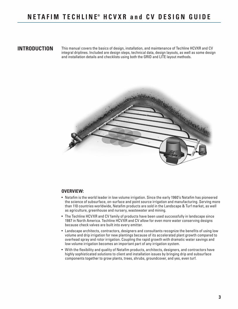
This manual covers the basics of design, installation, and maintenance of Techline HCVXR and CV integral driplines. Included are design steps, technical data, design layouts, as well as some design and installation details and checklists using both the GRID and LITE layout methods.
OVERVIEW:• Netafim is the world leader in low volume irrigation. Since the early 1960’s Netafim has pioneered
the science of subsurface, on-surface and point source irrigation and manufacturing. Serving more than 110 countries worldwide, Netafim products are sold in the Landscape & Turf market, as well as agriculture, greenhouse and nursery, wastewater and mining.
• The Techline HCVXR and CV family of products have been used successfully in landscape since 1987 in North America. Techline HCVXR and CV allow for even more water conserving designs because check valves are built into every emitter.
• Landscape architects, contractors, designers and consultants recognize the benefits of using low volume and drip irrigation for new plantings because of its accelerated plant growth compared to overhead spray and rotor irrigation. Coupling the rapid growth with dramatic water savings and low volume irrigation becomes an important part of any irrigation system.
• With the flexibility and quality of Netafim products, architects, designers, and contractors have highly sophisticated solutions to client and installation issues by bringing drip and subsurface components together to grow plants, trees, shrubs, groundcover, and yes, even turf.
INTRODUCTION
4
N E T A F I M T E C H L I N E® H C V X R a n d C V D E S I G N G U I D E
DESIGNCRITERIA
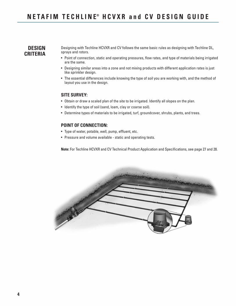
Designing with Techline HCVXR and CV follows the same basic rules as designing with Techline DL, sprays and rotors.• Point of connection, static and operating pressures, flow rates, and type of materials being irrigated
are the same.• Designing similar areas into a zone and not mixing products with different application rates is just
like sprinkler design.• The essential differences include knowing the type of soil you are working with, and the method of
layout you use in the design.
SITE SURVEY:• Obtain or draw a scaled plan of the site to be irrigated. Identify all slopes on the plan.• Identify the type of soil (sand, loam, clay or coarse soil).• Determine types of materials to be irrigated, turf, groundcover, shrubs, plants, and trees.
POINT OF CONNECTION:• Type of water, potable, well, pump, effluent, etc.• Pressure and volume available - static and operating tests.
Note: For Techline HCVXR and CV Technical Product Application and Specifications, see page 27 and 28.
5
N E T A F I M T E C H L I N E® H C V X R a n d C V D E S I G N G U I D E
BASICDESIGN
STEPS
WHEN SHOULD YOU USE TECHLINE HCVXR OR CV?• Anytime you want to create an even wetted pattern of water throughout an area.• Since the object of sprinklers is also to create an even wetted pattern, you can use Techline
HCVXR and CV anytime you can use sprinklers.
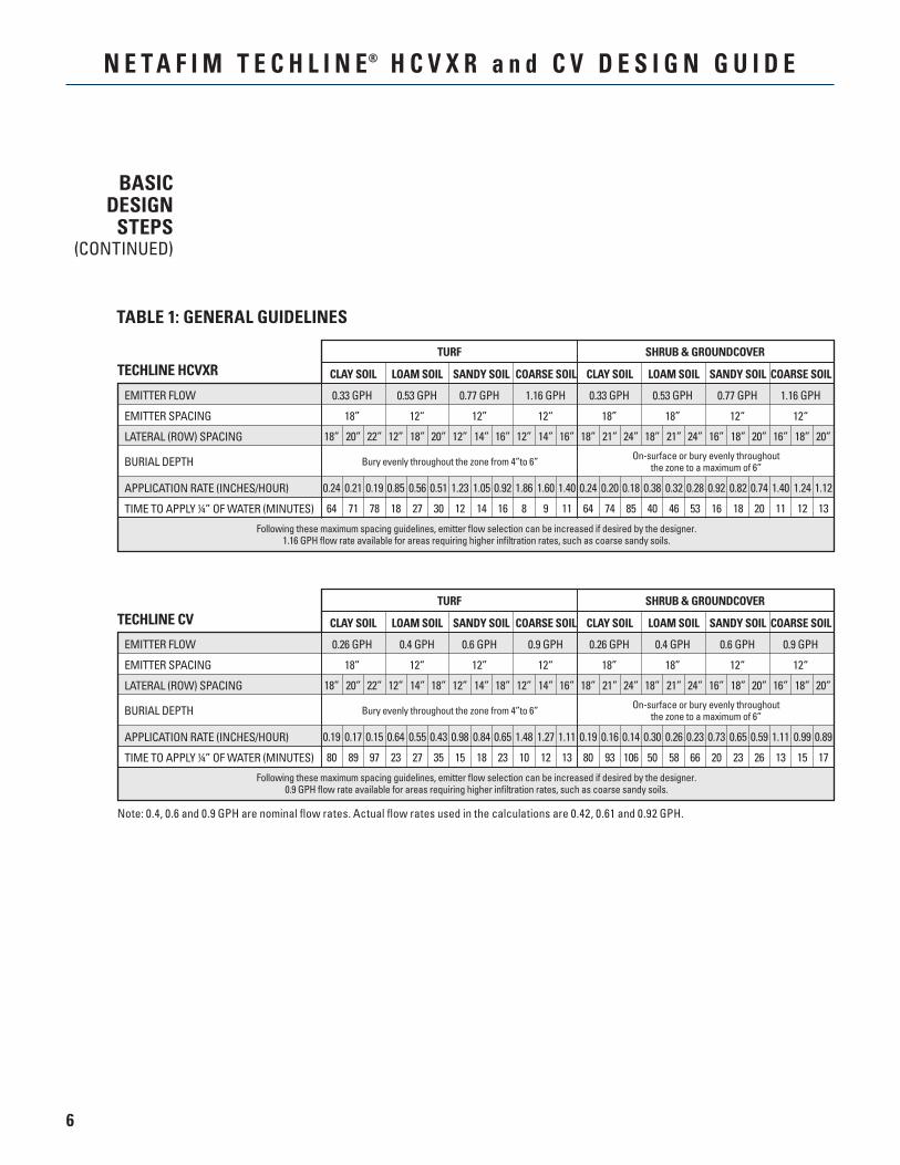
CHOOSING THE PROPER TECHLINE HCVXR OR CV:• From Table 1: General Guidelines (page 6), answer two questions: 1. Are you irrigating a Shrub and Groundcover area or Turf? 2. Is the soil Clay, Loam, Sandy or Coarse Soil?• Follow the proper column listed under Turf or Shrub & Groundcover to identify the proper Techline.
Example - If you choose Shrub and Groundcover, with loam soil, 0.4 GPH/18” Techline CV is the proper choice. (Each emitter will deliver 0.4 GPH and the emitters, mounted inside the tubing, are spaced 18” apart.)
• What other information is in the General Guidelines table? 1. How far to spread out the laterals is listed on the “Lateral (Row) Spacings” line. (For this example, rows should be evenly spaced anywhere from 18” - 24” apart.) 2. The corresponding application rates and time to apply are listed after the Lateral Spacings line.
(With rows of 0.4 GPH/18” Techline CV every 18” apart, the application rate is 0.30 inches per hour and it will take 50 minutes to apply 1/4” of water. If the rows are 24” apart, the application rate is 0.23 inches per hour, and it will take 66 minutes to apply 1/4” of water. For other row spacings see Application Rates Tables, pages 33 and 34.
6
N E T A F I M T E C H L I N E® H C V X R a n d C V D E S I G N G U I D E
BASICDESIGN
STEPS(CONTINUED)
TABLE 1: GENERAL GUIDELINES
TECHLINE HCVXR
EMITTER FLOW 0.33 GPH 0.53 GPH 0.77 GPH 1.16 GPH 0.33 GPH 0.53 GPH 0.77 GPH 1.16 GPH
EMITTER SPACING 18” 12“ 12” 12“ 18” 18” 12“ 12“
LATERAL (ROW) SPACING
APPLICATION RATE (INCHES/HOUR)
TIME TO APPLY ¼” OF WATER (MINUTES)
SHRUB & GROUNDCOVERTURF
CLAY SOIL LOAM SOIL SANDY SOIL COARSE SOIL CLAY SOIL LOAM SOIL SANDY SOIL COARSE SOIL
Following these maximum spacing guidelines, emitter flow selection can be increased if desired by the designer.1.16 GPH flow rate available for areas requiring higher infiltration rates, such as coarse sandy soils.
On-surface or bury evenly throughoutthe zone to a maximum of 6”Bury evenly throughout the zone from 4”to 6” BURIAL DEPTH
18” 20” 22” 12” 18” 20” 12” 14” 16” 12” 14” 16” 18” 21” 24” 18” 21” 24” 16” 18” 20” 16” 18” 20”
0.24 0.21 0.19 0.85 0.56 0.51 1.23 1.05 0.92 1.86 1.60 1.40 0.24 0.20 0.18 0.38 0.32 0.28 0.92 0.82 0.74 1.40 1.24 1.12
64 71 78 18 27 30 12 14 16 8 9 11 64 74 85 40 46 53 16 18 20 11 12 13
TECHLINE CV
EMITTER FLOW 0.26 GPH 0.4 GPH 0.6 GPH 0.9 GPH 0.26 GPH 0.4 GPH 0.6 GPH 0.9 GPH
EMITTER SPACING 18” 12“ 12” 12“ 18” 18” 12“ 12“
LATERAL (ROW) SPACING
APPLICATION RATE (INCHES/HOUR)
TIME TO APPLY ¼” OF WATER (MINUTES)
SHRUB & GROUNDCOVERTURF
CLAY SOIL LOAM SOIL SANDY SOIL COARSE SOIL CLAY SOIL LOAM SOIL SANDY SOIL COARSE SOIL
Following these maximum spacing guidelines, emitter flow selection can be increased if desired by the designer.0.9 GPH flow rate available for areas requiring higher infiltration rates, such as coarse sandy soils.
On-surface or bury evenly throughoutthe zone to a maximum of 6”Bury evenly throughout the zone from 4”to 6” BURIAL DEPTH
Note: 0.4, 0.6 and 0.9 GPH are nominal flow rates. Actual flow rates used in the calculations are 0.42, 0.61 and 0.92 GPH.
18” 20” 22” 12” 14” 18” 12” 14” 18” 12” 14” 16” 18” 21” 24” 18” 21” 24” 16” 18” 20” 16” 18” 20”
0.19 0.17 0.15 0.64 0.55 0.43 0.98 0.84 0.65 1.48 1.27 1.11 0.19 0.16 0.14 0.30 0.26 0.23 0.73 0.65 0.59 1.11 0.99 0.89
80 89 97 23 27 35 15 18 23 10 12 13 80 93 106 50 58 66 20 23 26 13 15 17
7
N E T A F I M T E C H L I N E® H C V X R a n d C V D E S I G N G U I D E
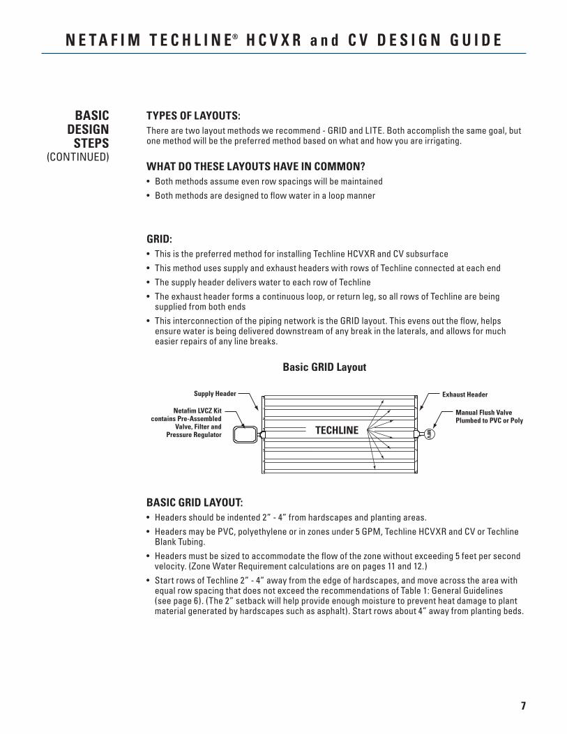
Basic GRID Layout
GRID:• This is the preferred method for installing Techline HCVXR and CV subsurface• This method uses supply and exhaust headers with rows of Techline connected at each end• The supply header delivers water to each row of Techline• The exhaust header forms a continuous loop, or return leg, so all rows of Techline are being
supplied from both ends• This interconnection of the piping network is the GRID layout. This evens out the flow, helps
ensure water is being delivered downstream of any break in the laterals, and allows for much easier repairs of any line breaks.
TYPES OF LAYOUTS:There are two layout methods we recommend - GRID and LITE. Both accomplish the same goal, but one method will be the preferred method based on what and how you are irrigating.
WHAT DO THESE LAYOUTS HAVE IN COMMON?• Both methods assume even row spacings will be maintained• Both methods are designed to flow water in a loop manner
BASIC GRID LAYOUT:• Headers should be indented 2” - 4” from hardscapes and planting areas.• Headers may be PVC, polyethylene or in zones under 5 GPM, Techline HCVXR and CV or Techline
Blank Tubing.• Headers must be sized to accommodate the flow of the zone without exceeding 5 feet per second
velocity. (Zone Water Requirement calculations are on pages 11 and 12.)• Start rows of Techline 2” - 4” away from the edge of hardscapes, and move across the area with
equal row spacing that does not exceed the recommendations of Table 1: General Guidelines (see page 6). (The 2” setback will help provide enough moisture to prevent heat damage to plant material generated by hardscapes such as asphalt). Start rows about 4” away from planting beds.
TECHLINE
Manual Flush ValvePlumbed to PVC or Poly
Exhaust HeaderSupply Header
MFV
Netafim LVCZ Kitcontains Pre-Assembled
Valve, Filter andPressure Regulator
BASICDESIGN
STEPS(CONTINUED)
8
N E T A F I M T E C H L I N E® H C V X R a n d C V D E S I G N G U I D E
Basic LITE Layout
BASICDESIGN
STEPS(CONTINUED)
HOW TO QUICKLY DETERMINE THE AMOUNT OF TECHLINE IN A ZONE(Square Footage of Zone x 12) ÷ Minimum Recommended Row Spacing
NOTE
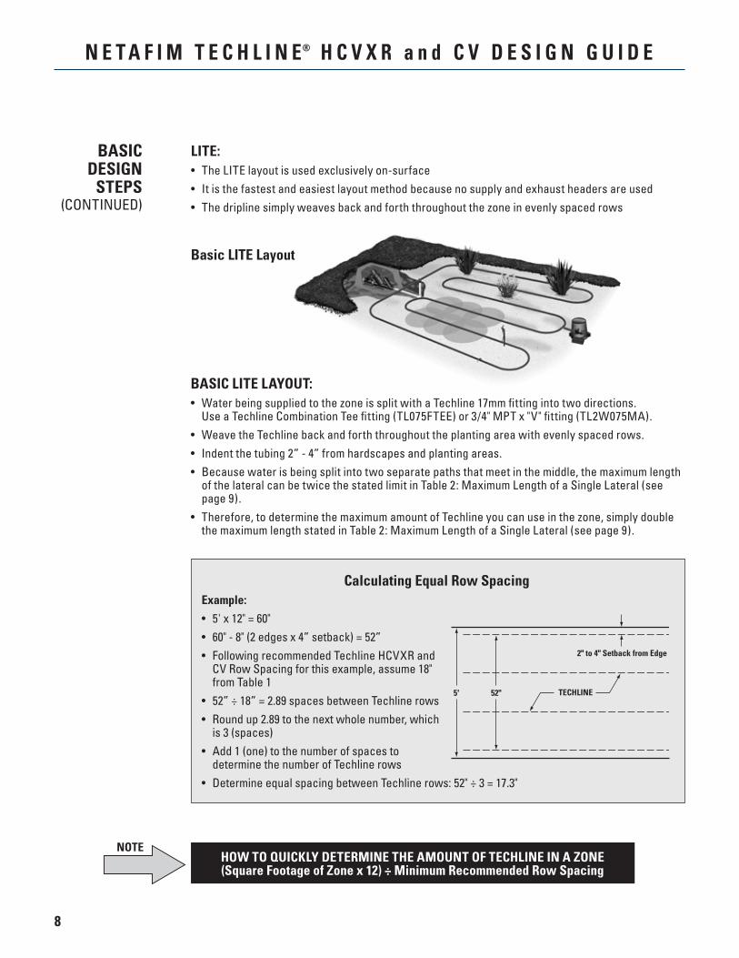
LITE:• The LITE layout is used exclusively on-surface• It is the fastest and easiest layout method because no supply and exhaust headers are used• The dripline simply weaves back and forth throughout the zone in evenly spaced rows
BASIC LITE LAYOUT:• Water being supplied to the zone is split with a Techline 17mm fitting into two directions.
Use a Techline Combination Tee fitting (TL075FTEE) or 3/4" MPT x "V" fitting (TL2W075MA).• Weave the Techline back and forth throughout the planting area with evenly spaced rows.• Indent the tubing 2” - 4” from hardscapes and planting areas.• Because water is being split into two separate paths that meet in the middle, the maximum length
of the lateral can be twice the stated limit in Table 2: Maximum Length of a Single Lateral (see page 9).
• Therefore, to determine the maximum amount of Techline you can use in the zone, simply double the maximum length stated in Table 2: Maximum Length of a Single Lateral (see page 9).
Calculating Equal Row Spacing Example:
• 5' x 12" = 60"• 60" - 8" (2 edges x 4” setback) = 52”• Following recommended Techline HCVXR and
CV Row Spacing for this example, assume 18" from Table 1
• 52” ÷ 18” = 2.89 spaces between Techline rows• Round up 2.89 to the next whole number, which
is 3 (spaces)• Add 1 (one) to the number of spaces to
determine the number of Techline rows• Determine equal spacing between Techline rows: 52" ÷ 3 = 17.3"
TECHLINE
2" to 4" Setback from Edge
5' 52"
9
N E T A F I M T E C H L I N E® H C V X R a n d C V D E S I G N G U I D E
BASICDESIGN
STEPS(CONTINUED)
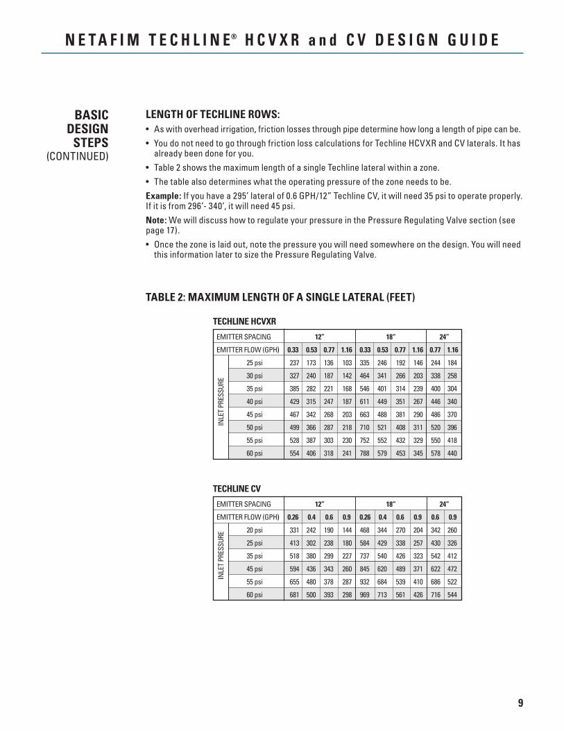
LENGTH OF TECHLINE ROWS:• As with overhead irrigation, friction losses through pipe determine how long a length of pipe can be.• You do not need to go through friction loss calculations for Techline HCVXR and CV laterals. It has
already been done for you.• Table 2 shows the maximum length of a single Techline lateral within a zone.• The table also determines what the operating pressure of the zone needs to be.Example: If you have a 295’ lateral of 0.6 GPH/12” Techline CV, it will need 35 psi to operate properly. If it is from 296’- 340’, it will need 45 psi.Note: We will discuss how to regulate your pressure in the Pressure Regulating Valve section (see page 17).• Once the zone is laid out, note the pressure you will need somewhere on the design. You will need
this information later to size the Pressure Regulating Valve.
TABLE 2: MAXIMUM LENGTH OF A SINGLE LATERAL (FEET)
INLE
T PR
ESSU
RE
TECHLINE HCVXR
25 psi
30 psi
35 psi
40 psi
45 psi
50 psi
55 psi
60 psi
EMITTER SPACING 12” 18“ 24”
EMITTER FLOW (GPH) 0.33 0.53 0.77 1.16 0.33 0.53 0.77 1.16 0.77 1.16
237 173 136 103 335 246 192 146 244 184
327 240 187 142 464 341 266 203 338 258
385 282 221 168 546 401 314 239 400 304
429 315 247 187 611 449 351 267 446 340
467 342 268 203 663 488 381 290 486 370
499 366 287 218 710 521 408 311 520 396
528 387 303 230 752 552 432 329 550 418
554 406 318 241 788 579 453 345 578 440
INLE
T PR
ESSU
RE
TECHLINE CV
20 psi
25 psi
35 psi
45 psi
55 psi
60 psi
EMITTER SPACING 12” 18“ 24”
EMITTER FLOW (GPH) 0.26 0.4 0.6 0.9 0.26 0.4 0.6 0.9 0.6 0.9
331 242 190 144 468 344 270 204 342 260
413 302 238 180 584 429 338 257 430 326
518 380 299 227 737 540 426 323 542 412
594 436 343 260 845 620 489 371 622 472
655 480 378 287 932 684 539 410 686 522
681 500 393 298 969 713 561 426 716 544
10
N E T A F I M T E C H L I N E® H C V X R a n d C V D E S I G N G U I D E
BASICDESIGN
STEPS(CONTINUED)
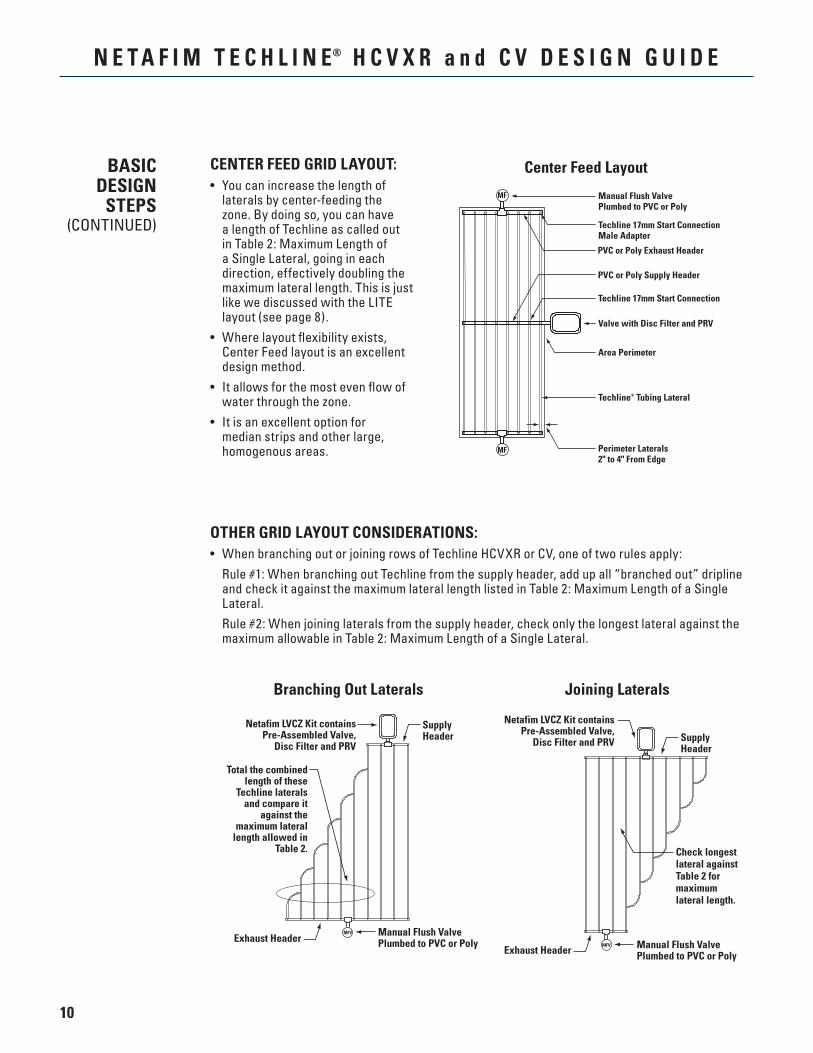
CENTER FEED GRID LAYOUT:• You can increase the length of
laterals by center-feeding the zone. By doing so, you can have a length of Techline as called out in Table 2: Maximum Length of a Single Lateral, going in each direction, effectively doubling the maximum lateral length. This is just like we discussed with the LITE layout (see page 8).
• Where layout flexibility exists, Center Feed layout is an excellent design method.
• It allows for the most even flow of water through the zone.
• It is an excellent option for median strips and other large, homogenous areas.
Manual Flush ValvePlumbed to PVC or Poly
Techline 17mm Start ConnectionMale Adapter
Valve with Disc Filter and PRV
Techline® Tubing Lateral
PVC or Poly Exhaust Header
MF
Techline 17mm Start Connection
PVC or Poly Supply Header
Area Perimeter
Perimeter Laterals2" to 4" From Edge
MF
Center Feed Layout
OTHER GRID LAYOUT CONSIDERATIONS:• When branching out or joining rows of Techline HCVXR or CV, one of two rules apply: Rule #1: When branching out Techline from the supply header, add up all “branched out” dripline
and check it against the maximum lateral length listed in Table 2: Maximum Length of a Single Lateral.
Rule #2: When joining laterals from the supply header, check only the longest lateral against the maximum allowable in Table 2: Maximum Length of a Single Lateral.
Branching Out Laterals
Total the combined length of these
Techline laterals and compare it
against the maximum lateral
length allowed in Table 2.
Manual Flush ValvePlumbed to PVC or Poly
SupplyHeader
MFV
Netafim LVCZ Kit containsPre-Assembled Valve,
Disc Filter and PRV
Exhaust Header
Check longestlateral againstTable 2 formaximumlateral length.
Manual Flush ValvePlumbed to PVC or Poly
SupplyHeader
MFV
Netafim LVCZ Kit containsPre-Assembled Valve,
Disc Filter and PRV
Exhaust Header
Joining Laterals
11
N E T A F I M T E C H L I N E® H C V X R a n d C V D E S I G N G U I D E
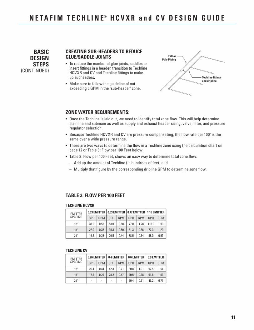
TABLE 3: FLOW PER 100 FEET
BASICDESIGN
STEPS(CONTINUED)
Techline fittingsand dripline
PVC orPoly Piping
CREATING SUB-HEADERS TO REDUCE GLUE/SADDLE JOINTS• To reduce the number of glue joints, saddles or
insert fittings in a header, transition to Techline HCVXR and CV and Techline fittings to make up subheaders.
• Make sure to follow the guideline of not exceeding 5 GPM in the 'sub-header' zone.
ZONE WATER REQUIREMENTS:• Once the Techline is laid out, we need to identify total zone flow. This will help determine
mainline and submain as well as supply and exhaust header sizing, valve, filter, and pressure regulator selection.
• Because Techline HCVXR and CV are pressure compensating, the flow rate per 100' is the same over a wide pressure range.
• There are two ways to determine the flow in a Techline zone using the calculation chart on page 12 or Table 3: Flow per 100 Feet below.
• Table 3: Flow per 100 Feet, shows an easy way to determine total zone flow: – Add up the amount of Techline (in hundreds of feet) and – Multiply that figure by the corresponding dripline GPM to determine zone flow.
TECHLINE HCVXR
12”
18”
24”
0.33 EMITTER 0.53 EMITTER 1.16 EMITTEREMITTERSPACING GPH GPM GPH GPM GPH GPM GPH GPM
33.0 0.55 53.0 0.88 77.0 1.28 116.0 1.93
22.0 0.37 35.3 0.59 51.3 0.86 77.3 1.29
16.5 0.28 26.5 0.44 38.5 0.64 58.0 0.97
0.77 EMITTER
TECHLINE CV
12”
18”
24”
0.26 EMITTER 0.4 EMITTER 0.9 EMITTEREMITTERSPACING GPH GPM GPH GPM GPH GPM GPH GPM
26.4 0.44 42.3 0.71 60.8 1.01 92.5 1.54
17.6 0.29 28.2 0.47 40.5 0.68 61.6 1.03
- - - - 30.4 0.51 46.2 0.77
0.6 EMITTER

12
N E T A F I M T E C H L I N E® H C V X R a n d C V D E S I G N G U I D E
Calculating Total Zone Water Demand• Multiply Total Feet x 12” = Total inches of Techline• Total Inches of Techline ÷ Emitter Spacing = Number of Emitters• Multiply Number of Emitters x Emitter Flow Rate (GPH) = Total GPH Flow• Total GPH Flow ÷ 60 = Total GPM in the Zone
Example:Ten 100’ rows of Techline with Emitter Spacing of 18”, Flow Rate is 0.6 GPH.
100’ x 10 = 1,000’ 1,000’ x 12” = 12,000” 12,000” ÷ 18” = 667 Emitters 667 Emitters x 0.61* GPH = 407 GPH Total Flow 407 GPH ÷ 60 = 6.78 GPM Flow in the Zone
BASICDESIGN
STEPS(CONTINUED)
*0.61 is the actual flow rate of the 0.6 GPH emitter and should be used in calculations for greatest accuracy.
13
N E T A F I M T E C H L I N E® H C V X R a n d C V D E S I G N G U I D E
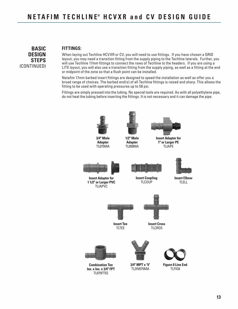
FITTINGS:When laying out Techline HCVXR or CV, you will need to use fittings. If you have chosen a GRID layout, you may need a transition fitting from the supply piping to the Techline laterals. Further, you will use Techline 17mm fittings to connect the rows of Techline to the headers. If you are using a LITE layout, you will also use a transition fitting from the supply piping, as well as a fitting at the end or midpoint of the zone so that a flush point can be installed.Netafim 17mm barbed insert fittings are designed to speed the installation as well as offer you a broad range of choices. The barbed end(s) of all Techline fittings is raised and sharp. This allows the fitting to be used with operating pressures up to 58 psi.Fittings are simply pressed into the tubing. No special tools are required. As with all polyethylene pipe, do not heat the tubing before inserting the fittings. It is not necessary and it can damage the pipe.
Insert CrossTLCROS
Combination TeeIns. x Ins. x 3/4" FPT
TL075FTEE
Insert TeeTLTEE
3/4" MPT x 'V'TL2W075MA
Figure 8 Line EndTLFIG8
Insert Adapter for1" or Larger PE
TLIAPE
Insert Adapter for1 1/2" or Larger PVC
TLIAPVC
3/4" MaleAdapter
TL075MA
1/2" MaleAdapter
TL050MA
Insert CouplingTLCOUP
Insert ElbowTLELL
BASICDESIGN
STEPS(CONTINUED)
14
N E T A F I M T E C H L I N E® H C V X R a n d C V D E S I G N G U I D E
LINE FLUSHING VALVES:Techline HCVXR and CV has a check valve in each emitter designed to hold back a 8.5' or 4.6' column of water (3.64 psi and 2 psi emitter closing pressure). Therefore, it may not be desirable to use an automatic flush valve with Techline HCVXR and CV, since it could allow water to drain from the dripline after zone shutdown.• Line flushing valves are used to provide a cleansing action in dripline each time the zone is
turned on.• When the zone is turned on, the flush valve begins dumping water into a sump located under it.• The dumping of water (additional flow) allows the velocity of water inside the dripline to increase
momentarily helping to clean the inside walls of the tubing.• This action moves sediments out of the zone and into the sump.
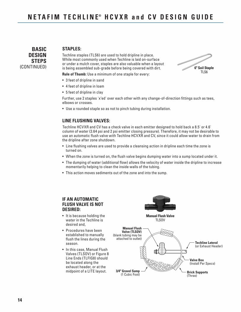
STAPLES:Techline staples (TLS6) are used to hold dripline in place.While most commonly used when Techline is laid on-surface or under a mulch cover, staples are also valuable when a layout is being assembled sub-grade before being covered with dirt.Rule of Thumb: Use a minimum of one staple for every:• 3 feet of dripline in sand• 4 feet of dripline in loam• 5 feet of dripline in clayFurther, use 2 staples 'x’ed' over each other with any change-of-direction fittings such as tees, elbows or crosses.• Use a rounded staple so as not to pinch tubing during installation.
IF AN AUTOMATIC FLUSH VALVE IS NOT DESIRED:• It is because holding the
water in the Techline is desired and,
• Procedures have been established to manually flush the lines during the season.
• In this case, Manual Flush Valves (TLSOV) or Figure 8 Line Ends (TLFIG8) should be located along the exhaust header, or at the midpoint of a LITE layout.
Manual FlushValve (TLSOV)
(blank tubing may beattached to outlet)
Techline Lateral(or Exhaust Header)
Valve Box(Install Per Specs)
Brick Supports(Three)
3/4" Gravel Sump(1 Cubic Foot)
BASICDESIGN
STEPS(CONTINUED) 6" Soil Staple
TLS6
Manual Flush ValveTLSOV
15
N E T A F I M T E C H L I N E® H C V X R a n d C V D E S I G N G U I D E
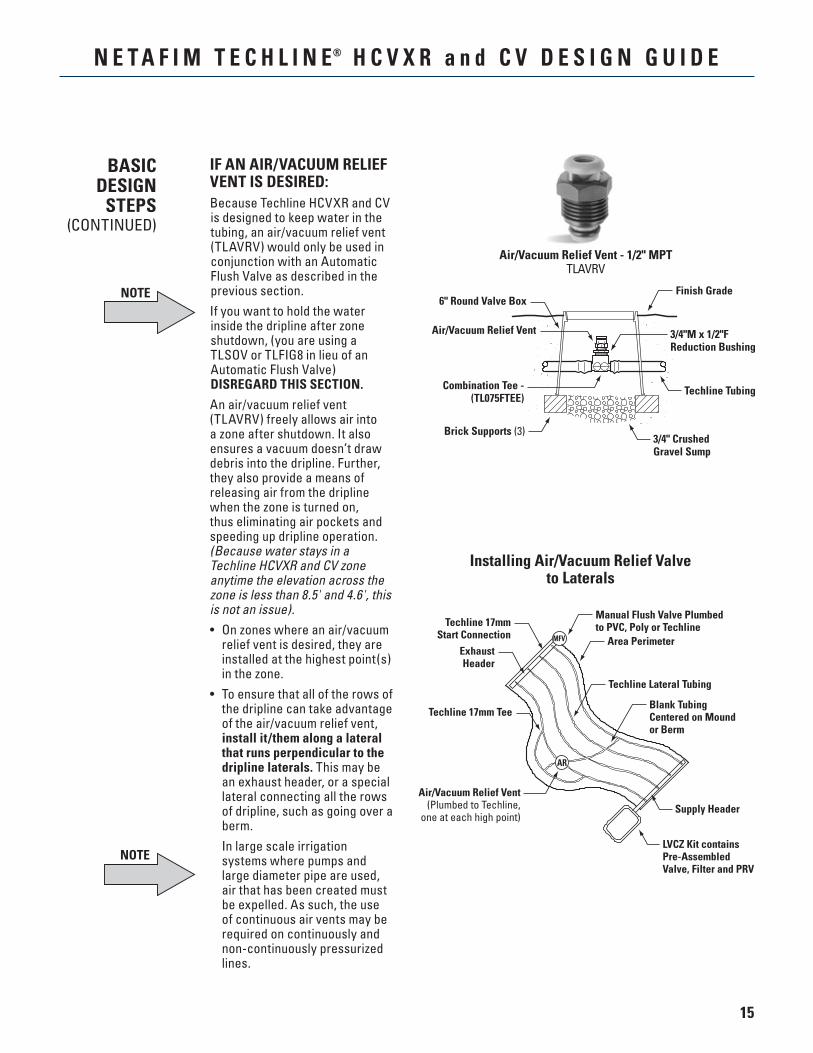
IF AN AIR/VACUUM RELIEF VENT IS DESIRED:Because Techline HCVXR and CV is designed to keep water in the tubing, an air/vacuum relief vent (TLAVRV) would only be used in conjunction with an Automatic Flush Valve as described in the previous section.If you want to hold the water inside the dripline after zone shutdown, (you are using a TLSOV or TLFIG8 in lieu of an Automatic Flush Valve) DISREGARD THIS SECTION.
An air/vacuum relief vent (TLAVRV) freely allows air into a zone after shutdown. It also ensures a vacuum doesn’t draw debris into the dripline. Further, they also provide a means of releasing air from the dripline when the zone is turned on, thus eliminating air pockets and speeding up dripline operation. (Because water stays in a Techline HCVXR and CV zone anytime the elevation across the zone is less than 8.5' and 4.6', this is not an issue).• On zones where an air/vacuum
relief vent is desired, they are installed at the highest point(s) in the zone.
• To ensure that all of the rows of the dripline can take advantage of the air/vacuum relief vent, install it/them along a lateral that runs perpendicular to the dripline laterals. This may be an exhaust header, or a special lateral connecting all the rows of dripline, such as going over a berm.
In large scale irrigation systems where pumps and large diameter pipe are used, air that has been created must be expelled. As such, the use of continuous air vents may be required on continuously and non-continuously pressurized lines.
Installing Air/Vacuum Relief Valveto Laterals
BASICDESIGN
STEPS(CONTINUED)
NOTE
NOTE
Air/Vacuum Relief Vent - 1/2" MPTTLAVRV
6" Round Valve Box
Air/Vacuum Relief Vent
Combination Tee -(TL075FTEE)
3/4"M x 1/2"FReduction Bushing
Finish Grade
Techline Tubing
3/4" CrushedGravel Sump
Brick Supports (3)
Techline 17mmStart Connection
Manual Flush Valve Plumbedto PVC, Poly or Techline
Area Perimeter
Techline Lateral Tubing
Blank TubingCentered on Moundor Berm
Supply Header
LVCZ Kit containsPre-AssembledValve, Filter and PRV
ExhaustHeader
Techline 17mm Tee
Air/Vacuum Relief Vent(Plumbed to Techline,
one at each high point)
MFV
AR
16
N E T A F I M T E C H L I N E® H C V X R a n d C V D E S I G N G U I D E
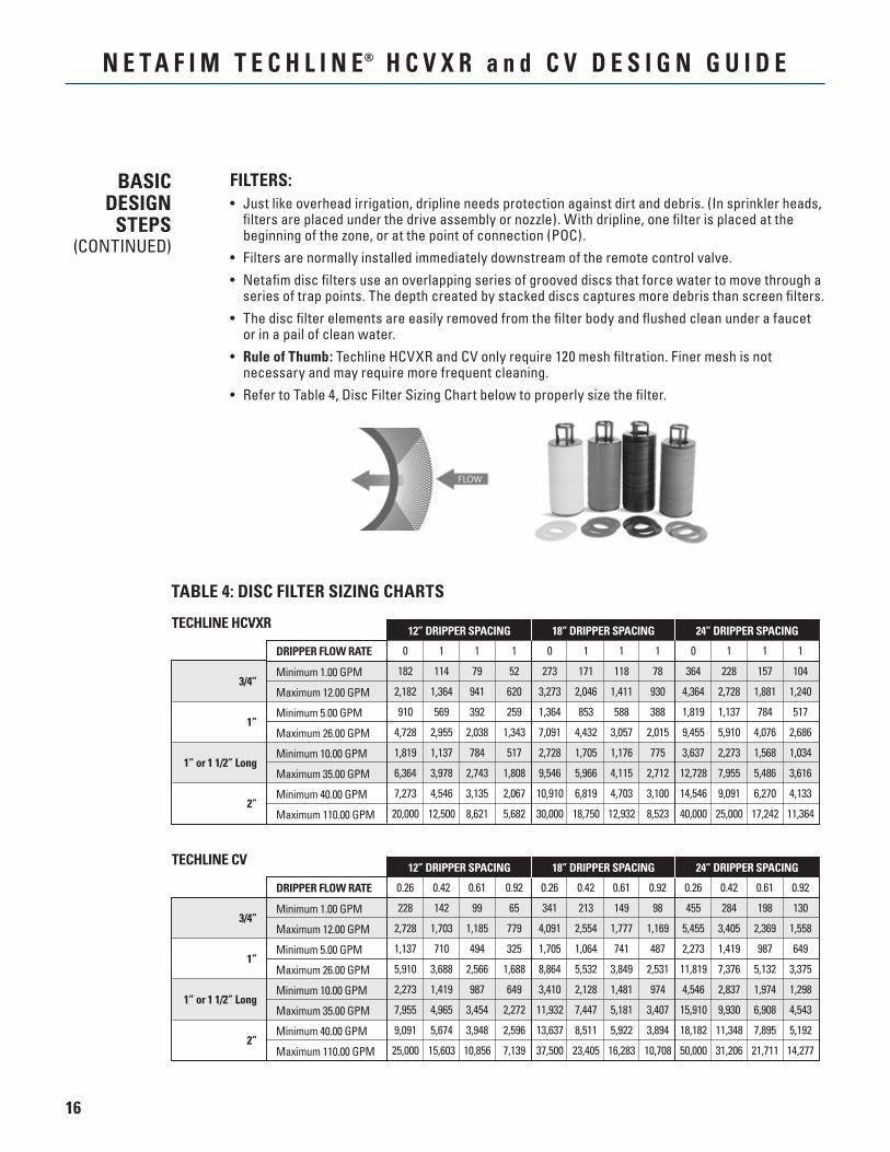
FILTERS:• Just like overhead irrigation, dripline needs protection against dirt and debris. (In sprinkler heads,
filters are placed under the drive assembly or nozzle). With dripline, one filter is placed at the beginning of the zone, or at the point of connection (POC).
• Filters are normally installed immediately downstream of the remote control valve.• Netafim disc filters use an overlapping series of grooved discs that force water to move through a
series of trap points. The depth created by stacked discs captures more debris than screen filters.• The disc filter elements are easily removed from the filter body and flushed clean under a faucet
or in a pail of clean water.• Rule of Thumb: Techline HCVXR and CV only require 120 mesh filtration. Finer mesh is not
necessary and may require more frequent cleaning.• Refer to Table 4, Disc Filter Sizing Chart below to properly size the filter.
BASICDESIGN
STEPS(CONTINUED)
TECHLINE HCVXR
3/4”
1”
1” or 1 1/2” Long
2”
0 1 1 1 0 1 1 1 0 1 1 1
182 114 79 52 273 171 118 78 364 228 157 104
2,182 1,364 941 620 3,273 2,046 1,411 930 4,364 2,728 1,881 1,240
910 569 392 259 1,364 853 588 388 1,819 1,137 784 517
4,728 2,955 2,038 1,343 7,091 4,432 3,057 2,015 9,455 5,910 4,076 2,686
1,819 1,137 784 517 2,728 1,705 1,176 775 3,637 2,273 1,568 1,034
6,364 3,978 2,743 1,808 9,546 5,966 4,115 2,712 12,728 7,955 5,486 3,616
7,273 4,546 3,135 2,067 10,910 6,819 4,703 3,100 14,546 9,091 6,270 4,133
20,000 12,500 8,621 5,682 30,000 18,750 12,932 8,523 40,000 25,000 17,242 11,364
Minimum 1.00 GPM
Maximum 12.00 GPM
Minimum 5.00 GPM
Maximum 26.00 GPM
Minimum 10.00 GPM
Maximum 35.00 GPM
Minimum 40.00 GPM
Maximum 110.00 GPM
DRIPPER FLOW RATE
12” DRIPPER SPACING 18” DRIPPER SPACING 24” DRIPPER SPACING
TECHLINE CV
3/4”
1”
1” or 1 1/2” Long
2”
0.26 0.42 0.61 0.92 0.26 0.42 0.61 0.92 0.26 0.42 0.61 0.92
228 142 99 65 341 213 149 98 455 284 198 130
2,728 1,703 1,185 779 4,091 2,554 1,777 1,169 5,455 3,405 2,369 1,558
1,137 710 494 325 1,705 1,064 741 487 2,273 1,419 987 649
5,910 3,688 2,566 1,688 8,864 5,532 3,849 2,531 11,819 7,376 5,132 3,375
2,273 1,419 987 649 3,410 2,128 1,481 974 4,546 2,837 1,974 1,298
7,955 4,965 3,454 2,272 11,932 7,447 5,181 3,407 15,910 9,930 6,908 4,543
9,091 5,674 3,948 2,596 13,637 8,511 5,922 3,894 18,182 11,348 7,895 5,192
25,000 15,603 10,856 7,139 37,500 23,405 16,283 10,708 50,000 31,206 21,711 14,277
Minimum 1.00 GPM
Maximum 12.00 GPM
Minimum 5.00 GPM
Maximum 26.00 GPM
Minimum 10.00 GPM
Maximum 35.00 GPM
Minimum 40.00 GPM
Maximum 110.00 GPM
DRIPPER FLOW RATE
12” DRIPPER SPACING 18” DRIPPER SPACING 24” DRIPPER SPACING
TABLE 4: DISC FILTER SIZING CHARTS
17
N E T A F I M T E C H L I N E® H C V X R a n d C V D E S I G N G U I D E
PRESSURE REGULATING VALVES (PRV):Pressure regulating valves reduce the operating pressure so that Techline zones operate between 14 to 58 psi for Techline CV and 21.8 to 58 psi for Techline HCVXR.• PRVs are normally installed immediately downstream of the disc filter and control valve. Often
all three components are in the same valve box, and the distance from the PRV to the Techline is limited so additional friction is not incurred.
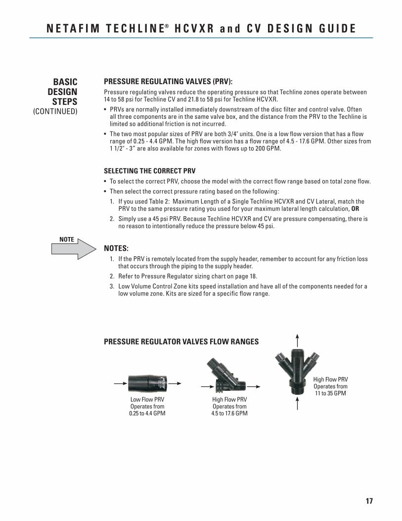
• The two most popular sizes of PRV are both 3/4" units. One is a low flow version that has a flow range of 0.25 - 4.4 GPM. The high flow version has a flow range of 4.5 - 17.6 GPM. Other sizes from 1 1/2" - 3” are also available for zones with flows up to 200 GPM.
SELECTING THE CORRECT PRV• To select the correct PRV, choose the model with the correct flow range based on total zone flow.• Then select the correct pressure rating based on the following: 1. If you used Table 2: Maximum Length of a Single Techline HCVXR and CV Lateral, match the
PRV to the same pressure rating you used for your maximum lateral length calculation, OR
2. Simply use a 45 psi PRV. Because Techline HCVXR and CV are pressure compensating, there is no reason to intentionally reduce the pressure below 45 psi.
NOTES: 1. If the PRV is remotely located from the supply header, remember to account for any friction loss
that occurs through the piping to the supply header. 2. Refer to Pressure Regulator sizing chart on page 18. 3. Low Volume Control Zone kits speed installation and have all of the components needed for a
low volume zone. Kits are sized for a specific flow range.
BASICDESIGN
STEPS(CONTINUED)
PRESSURE REGULATOR VALVES FLOW RANGES
High Flow PRVOperates from 11 to 35 GPM
Low Flow PRVOperates from 0.25 to 4.4 GPM
High Flow PRVOperates from 4.5 to 17.6 GPM
NOTE
18
N E T A F I M T E C H L I N E® H C V X R a n d C V D E S I G N G U I D E
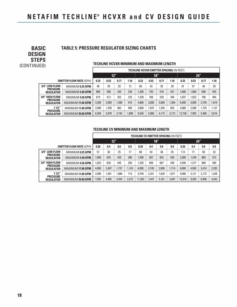
TECHLINE CV MINIMUM AND MAXIMUM LENGTH
12” 18” 24”
MINIMUM 0.25 GPM
MAXIMUM 4.40 GPM
MINIMUM 4.50 GPM
MAXIMUM 17.60 GPM
MINIMUM 11.00 GPM
MAXIMUM 35.00 GPM
3/4” LOW FLOWPRESSURE
REGULATOR3/4” HIGH FLOW
PRESSUREREGULATOR
1 1/2”PRESSURE
REGULATOR
0.26 0.4 0.6 0.9 0.26 0.4 0.6 0.9 0.26 0.4 0.6 0.9
57 36 25 17 86 54 38 25 114 71 50 33
1,000 625 435 286 1,500 937 652 429 2,000 1,249 869 572
1,023 639 445 293 1,535 958 667 439 2,046 1,277 889 585
4,000 2,497 1,737 1,143 6,000 3,745 2,606 1,714 8,000 4,993 3,474 2,285
2,500 1,561 1,086 714 3,750 2,341 1,629 1,071 5,000 3,121 2,172 1,428
7,955 4,965 3,454 2,272 11,932 7,447 5,181 3,407 15,910 9,930 6,908 4,543
TECHLINE CV EMITTER SPACING (IN FEET)
EMITTER FLOW RATE (GPH)
TECHLINE HCVXR MINIMUM AND MAXIMUM LENGTH
12” 18” 24”
MINIMUM 0.25 GPM
MAXIMUM 4.40 GPM
MINIMUM 4.50 GPM
MAXIMUM 17.60 GPM
MINIMUM 11.00 GPM
MAXIMUM 35.00 GPM
3/4” LOW FLOWPRESSURE
REGULATOR3/4” HIGH FLOW
PRESSUREREGULATOR
1 1/2”PRESSURE
REGULATOR
0.33 0.53 0.77 1.16 0.33 0.53 0.77 1.16 0.33 0.53 0.77 1.16
46 29 20 13 69 43 30 20 91 57 40 26
800 500 345 228 1,200 750 518 341 1,600 1,000 690 455
819 512 353 233 1,228 768 529 349 1,637 1,023 706 465
3,200 2,000 1,380 910 4,800 3,000 2,069 1,364 6,400 4,000 2,759 1,819
2,000 1,250 863 569 3,000 1,875 1,294 853 4,000 2,500 1,725 1,137
6,364 3,978 2,743 1,808 9,546 5,966 4,115 2,712 12,728 7,955 5,486 3,616
TECHLINE HCVXR EMITTER SPACING (IN FEET)
EMITTER FLOW RATE (GPH)
TABLE 5: PRESSURE REGULATOR SIZING CHARTSBASICDESIGN
STEPS(CONTINUED)
19
N E T A F I M T E C H L I N E® H C V X R a n d C V D E S I G N G U I D E
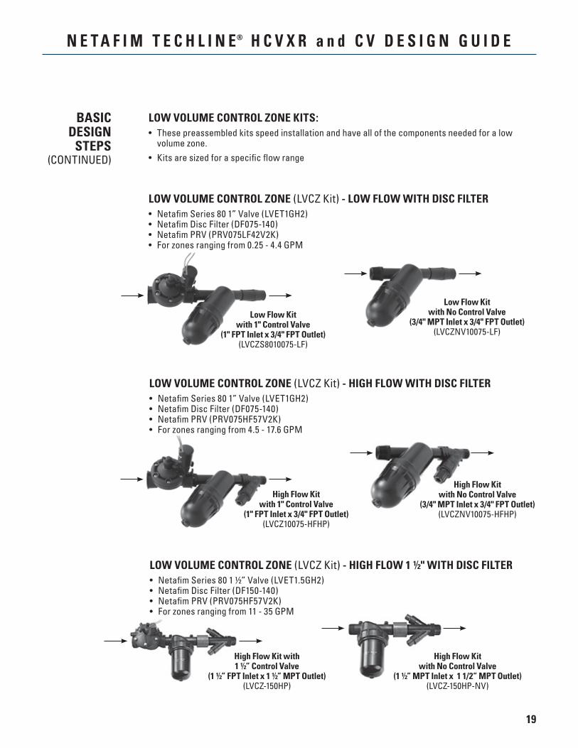
LOW VOLUME CONTROL ZONE (LVCZ Kit) - LOW FLOW WITH DISC FILTER• Netafim Series 80 1” Valve (LVET1GH2)• Netafim Disc Filter (DF075-140)• Netafim PRV (PRV075LF42V2K)• For zones ranging from 0.25 - 4.4 GPM
High Flow Kitwith 1" Control Valve
(1" FPT Inlet x 3/4" FPT Outlet)(LVCZ10075-HFHP)
Low Flow Kitwith 1" Control Valve
(1" FPT Inlet x 3/4" FPT Outlet)(LVCZS8010075-LF)
Low Flow Kitwith No Control Valve
(3/4" MPT Inlet x 3/4" FPT Outlet)(LVCZNV10075-LF)
High Flow Kitwith No Control Valve
(3/4" MPT Inlet x 3/4" FPT Outlet)(LVCZNV10075-HFHP)
LOW VOLUME CONTROL ZONE (LVCZ Kit) - HIGH FLOW WITH DISC FILTER• Netafim Series 80 1” Valve (LVET1GH2)• Netafim Disc Filter (DF075-140)• Netafim PRV (PRV075HF57V2K)• For zones ranging from 4.5 - 17.6 GPM
BASICDESIGN
STEPS(CONTINUED)
LOW VOLUME CONTROL ZONE KITS:• These preassembled kits speed installation and have all of the components needed for a low
volume zone.• Kits are sized for a specific flow range
LOW VOLUME CONTROL ZONE (LVCZ Kit) - HIGH FLOW 1 ½" WITH DISC FILTER• Netafim Series 80 1 ½” Valve (LVET1.5GH2)• Netafim Disc Filter (DF150-140)• Netafim PRV (PRV075HF57V2K)• For zones ranging from 11 - 35 GPM
High Flow Kitwith No Control Valve
(1 ½” MPT Inlet x 1 1/2” MPT Outlet)(LVCZ-150HP-NV)
High Flow Kit with1 ½” Control Valve
(1 ½” FPT Inlet x 1 ½” MPT Outlet)(LVCZ-150HP)
20
N E T A F I M T E C H L I N E® H C V X R a n d C V D E S I G N G U I D E
BASICDESIGN
STEPS(CONTINUED)
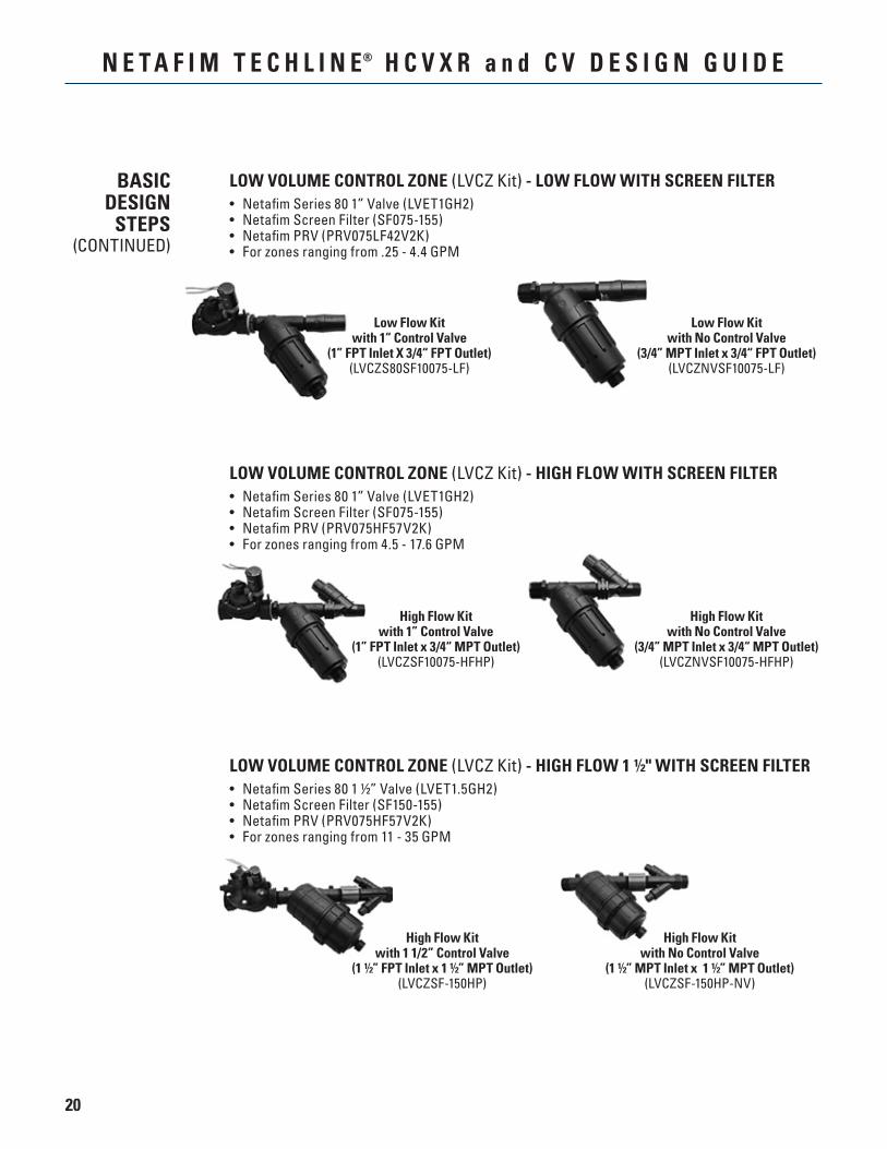
Low Flow Kitwith No Control Valve
(3/4” MPT Inlet x 3/4“ FPT Outlet)(LVCZNVSF10075-LF)
Low Flow Kitwith 1“ Control Valve
(1” FPT Inlet X 3/4“ FPT Outlet)(LVCZS80SF10075-LF)
LOW VOLUME CONTROL ZONE (LVCZ Kit) - LOW FLOW WITH SCREEN FILTER• Netafim Series 80 1” Valve (LVET1GH2)• Netafim Screen Filter (SF075-155)• Netafim PRV (PRV075LF42V2K)• For zones ranging from .25 - 4.4 GPM
High Flow Kitwith No Control Valve
(3/4” MPT Inlet x 3/4“ MPT Outlet)(LVCZNVSF10075-HFHP)
High Flow Kitwith 1” Control Valve
(1” FPT Inlet x 3/4“ MPT Outlet)(LVCZSF10075-HFHP)
LOW VOLUME CONTROL ZONE (LVCZ Kit) - HIGH FLOW WITH SCREEN FILTER• Netafim Series 80 1” Valve (LVET1GH2)• Netafim Screen Filter (SF075-155)• Netafim PRV (PRV075HF57V2K)• For zones ranging from 4.5 - 17.6 GPM
LOW VOLUME CONTROL ZONE (LVCZ Kit) - HIGH FLOW 1 ½" WITH SCREEN FILTER• Netafim Series 80 1 ½” Valve (LVET1.5GH2)• Netafim Screen Filter (SF150-155)• Netafim PRV (PRV075HF57V2K)• For zones ranging from 11 - 35 GPM
High Flow Kitwith No Control Valve
(1 ½” MPT Inlet x 1 ½” MPT Outlet)(LVCZSF-150HP-NV)
High Flow Kitwith 1 1/2” Control Valve
(1 ½” FPT Inlet x 1 ½” MPT Outlet)(LVCZSF-150HP)
21
N E T A F I M T E C H L I N E® H C V X R a n d C V D E S I G N G U I D E
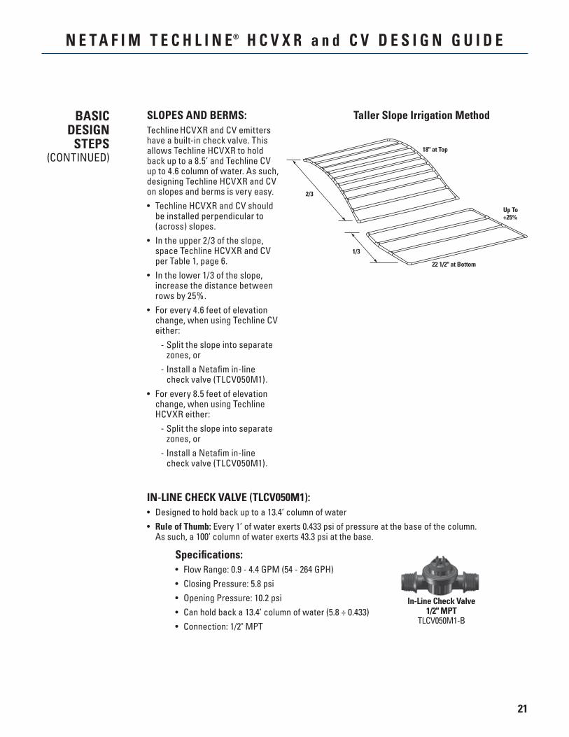
18" at Top
Up To+25%
22 1/2" at Bottom
2/3
1/3
SLOPES AND BERMS:Techline HCVXR and CV emitters have a built-in check valve. This allows Techline HCVXR to hold back up to a 8.5’ and Techline CV up to 4.6 column of water. As such, designing Techline HCVXR and CV on slopes and berms is very easy.• Techline HCVXR and CV should
be installed perpendicular to (across) slopes.
• In the upper 2/3 of the slope, space Techline HCVXR and CV per Table 1, page 6.
• In the lower 1/3 of the slope, increase the distance between rows by 25%.
• For every 4.6 feet of elevation change, when using Techline CV either:
- Split the slope into separate zones, or
- Install a Netafim in-line check valve (TLCV050M1).
• For every 8.5 feet of elevation change, when using Techline HCVXR either:
- Split the slope into separate zones, or
- Install a Netafim in-line check valve (TLCV050M1).
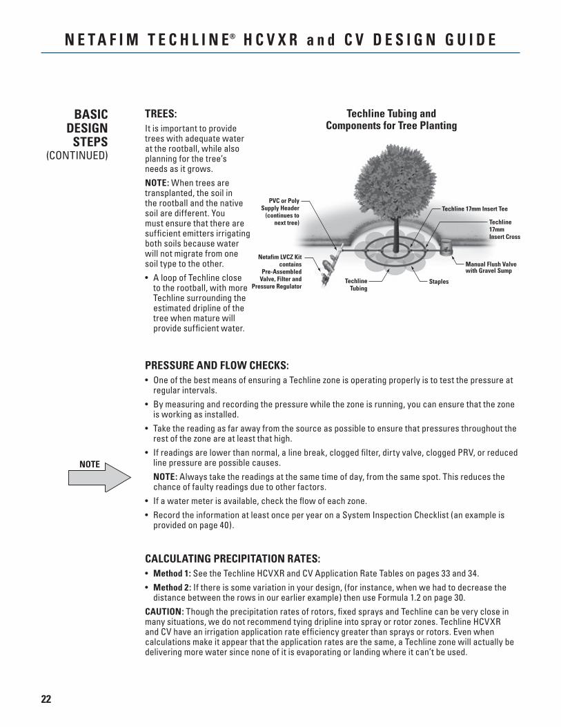
Specifications:• Flow Range: 0.9 - 4.4 GPM (54 - 264 GPH)• Closing Pressure: 5.8 psi• Opening Pressure: 10.2 psi• Can hold back a 13.4’ column of water (5.8 ÷ 0.433)• Connection: 1/2" MPT
Taller Slope Irrigation Method
IN-LINE CHECK VALVE (TLCV050M1):• Designed to hold back up to a 13.4’ column of water• Rule of Thumb: Every 1’ of water exerts 0.433 psi of pressure at the base of the column.
As such, a 100’ column of water exerts 43.3 psi at the base.
BASICDESIGN
STEPS(CONTINUED)
In-Line Check Valve1/2" MPT
TLCV050M1-B
22
N E T A F I M T E C H L I N E® H C V X R a n d C V D E S I G N G U I D E
PRESSURE AND FLOW CHECKS:• One of the best means of ensuring a Techline zone is operating properly is to test the pressure at
regular intervals.• By measuring and recording the pressure while the zone is running, you can ensure that the zone
is working as installed.• Take the reading as far away from the source as possible to ensure that pressures throughout the
rest of the zone are at least that high.• If readings are lower than normal, a line break, clogged filter, dirty valve, clogged PRV, or reduced
line pressure are possible causes. NOTE: Always take the readings at the same time of day, from the same spot. This reduces the
chance of faulty readings due to other factors.• If a water meter is available, check the flow of each zone.• Record the information at least once per year on a System Inspection Checklist (an example is
provided on page 40).
CALCULATING PRECIPITATION RATES:• Method 1: See the Techline HCVXR and CV Application Rate Tables on pages 33 and 34.• Method 2: If there is some variation in your design, (for instance, when we had to decrease the
distance between the rows in our earlier example) then use Formula 1.2 on page 30.CAUTION: Though the precipitation rates of rotors, fixed sprays and Techline can be very close in many situations, we do not recommend tying dripline into spray or rotor zones. Techline HCVXR and CV have an irrigation application rate efficiency greater than sprays or rotors. Even when calculations make it appear that the application rates are the same, a Techline zone will actually be delivering more water since none of it is evaporating or landing where it can’t be used.
BASICDESIGN
STEPS(CONTINUED)
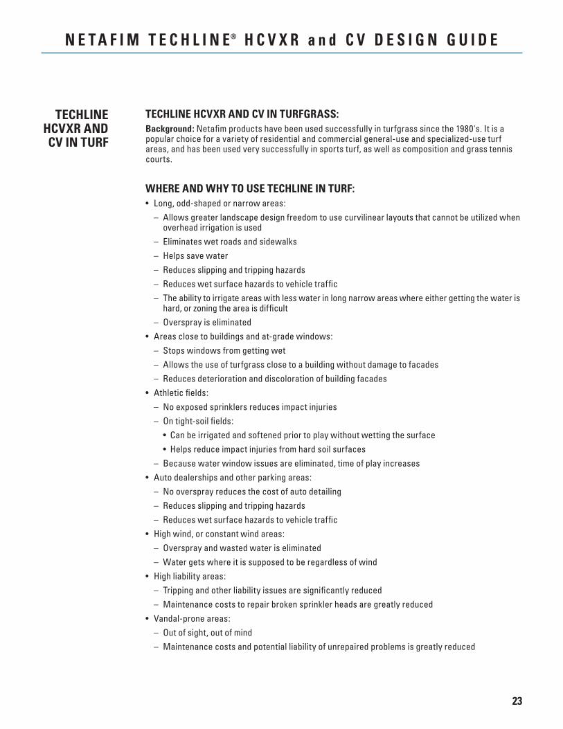
Techline Tubing andComponents for Tree Planting
TREES:It is important to provide trees with adequate water at the rootball, while also planning for the tree’s needs as it grows.NOTE: When trees are transplanted, the soil in the rootball and the native soil are different. You must ensure that there are sufficient emitters irrigating both soils because water will not migrate from one soil type to the other.• A loop of Techline close
to the rootball, with more Techline surrounding the estimated dripline of the tree when mature will provide sufficient water.
PVC or PolySupply Header
(continues tonext tree)
Techline 17mm Insert Tee
Techline17mmInsert Cross
Manual Flush Valvewith Gravel Sump
StaplesTechlineTubing
Netafim LVCZ Kitcontains
Pre-AssembledValve, Filter and
Pressure Regulator
NOTE
23
N E T A F I M T E C H L I N E® H C V X R a n d C V D E S I G N G U I D E
TECHLINE HCVXR AND CV IN TURFGRASS:Background: Netafim products have been used successfully in turfgrass since the 1980's. It is a popular choice for a variety of residential and commercial general-use and specialized-use turf areas, and has been used very successfully in sports turf, as well as composition and grass tennis courts.
WHERE AND WHY TO USE TECHLINE IN TURF:• Long, odd-shaped or narrow areas: – Allows greater landscape design freedom to use curvilinear layouts that cannot be utilized when
overhead irrigation is used – Eliminates wet roads and sidewalks – Helps save water – Reduces slipping and tripping hazards – Reduces wet surface hazards to vehicle traffic – The ability to irrigate areas with less water in long narrow areas where either getting the water is
hard, or zoning the area is difficult – Overspray is eliminated• Areas close to buildings and at-grade windows: – Stops windows from getting wet – Allows the use of turfgrass close to a building without damage to facades – Reduces deterioration and discoloration of building facades• Athletic fields: – No exposed sprinklers reduces impact injuries – On tight-soil fields: • Can be irrigated and softened prior to play without wetting the surface • Helps reduce impact injuries from hard soil surfaces – Because water window issues are eliminated, time of play increases• Auto dealerships and other parking areas: – No overspray reduces the cost of auto detailing – Reduces slipping and tripping hazards – Reduces wet surface hazards to vehicle traffic• High wind, or constant wind areas: – Overspray and wasted water is eliminated – Water gets where it is supposed to be regardless of wind• High liability areas: – Tripping and other liability issues are significantly reduced – Maintenance costs to repair broken sprinkler heads are greatly reduced• Vandal-prone areas: – Out of sight, out of mind – Maintenance costs and potential liability of unrepaired problems is greatly reduced
TECHLINE HCVXR AND CV IN TURF
24
N E T A F I M T E C H L I N E® H C V X R a n d C V D E S I G N G U I D E
• Wood hardscapes: – Bleaching of hardscapes such as wooden fences is eliminated – Aesthetics of the wood hardscapes is maintained• Steep slopes: – Allows turf to be used on slopes – Water is easily managed on slopes with dripline – Wash outs are eliminated• Locales where the cost of water is too expensive for overhead irrigation• Unlike spray or rotor irrigation, which does not have an even application rate across its pattern,
Techline HCVXR and CV have an extremely well-balanced application rate in the entire area. As such, you do not need to overwater to make sure the driest area receives enough water.
– Techline HCVXR and CV use about half of the water of an overhead system – Techline HCVXR and CV are about 90% efficient vs. overhead irrigation, which is about 60%
efficient• Water window issues: – Irrigate whenever necessary because there is no exposed spray• Recycled/reclaimed water or fertigation applications where spraying water is illegal: – Allows for use of nutrient-rich water, often at a greatly reduced cost – Saves potable water supplies
TIPS FOR USING TECHLINE HCVXR AND CV IN A NEWLY-SODDED LAWN:• Use Table 1: General Guidelines recommendations for turf, see page 6.• Bury the Techline approximately 4” below final grade• In areas where mechanical aeration will be used, bury the Techline 6” below final grade and
ensure aeration does not exceed 4"• When installing the sod: – It is important the final grade is smooth, ensuring that the sod makes solid contact with the soil – Properly 'knit' the edges together – Thoroughly wet the sod with overhead irrigation – Roll the sod to ensure good contact• If the irrigation system is automatic: – Set the zone to run several times daily – Keep wetted from above as necessary until the roots establish• Once you cannot pull the edges of the sod up, discontinue overhead watering• Irrigate on a daily or every-other-day basis• Techline HCVXR and CV have a patented emitter design with a built-in physical root barrier in
each emitter• Techline HCVXR offers additional root intrusion protection with Cupron® copper oxide which is
embedded in the emitter resin during the manufacturing process. It will not wash off, wear off or leach out of the emitter for long lasting root intrusion protection throughout the life of the dripline.
TECHLINE HCVXR AND CV IN TURF
25
N E T A F I M T E C H L I N E® H C V X R a n d C V D E S I G N G U I D E
SPECIAL APPLICATIONS
AND TIPS
PARKING LOT ISLANDS:If islands are small, consider tying several of them together on the same zone.• Once you have determined that the conditions of the islands are similar enough to interconnect
them, design each for the same precipitation rate by using the same Techline HCVXR and CV and spacing.
• Use one Low Volume Control Zone kit at the source, and install a manual flush valve (TLSOV) or figure 8 line end (TLFIG8) either at the end of the last island or, if the islands dead-end, on each island.
• Connections between the islands should be PVC, or as called out by the designer or local codes.
ELECTRICAL GROUNDING:• The effectiveness of electrical grounding is dependent on the soil and its moisture content. In
moist soil, grounding is more effective than in dry soil.• One method of ensuring moist soil is to install a length of Techline HCVXR and CV along a length of
unclad copper wire being used for grounding purposes. The Techline HCVXR and CV are installed in the usual method. Run it from a separate station on the controller to give you maximum control.
• Techline HCVXR and CV can also be installed over the top of a grounding plate or ground rod.
ABOVE AND BELOW GRADE:Techline HCVXR and CV are designed to be used in a variety of ways:• It can be laid on the surface and held in place with Techline staples (TLS6),• It can be buried below grade.
NOTE: When using Techline HCVXR and CV above grade with staples, use enough staples to firmly hold the tubing in place, especially in freezing climates.
NOTE
26
N E T A F I M T E C H L I N E® H C V X R a n d C V D E S I G N G U I D E
WINTERIZING INSTRUCTIONS:Winterizing an irrigation system involves removing enough water to ensure that components do not crack or break during freezing weather.Because Techline HCVXR and CV are designed to keep water sealed inside the tubing between irrigations, it is important that these simple steps be followed.
MANUAL WINTERIZATION (no compressed air blow-out)• A drain port must be present at all low points in the zone. • Ports may be a tee or elbow with a threaded plug, a Netafim figure 8 line end (TLFIG8) or manual
flush valve (TLSOV) which, when opened, will allow water to drain. If a Netafim automatic flush valve has been used, disassemble it.
• If the Techline zone is a grid or closed system, the supply and exhaust headers may contain a significant amount of water because they are either blank Techline tubing, PVC, or poly pipe. It is important to provide drain ports for these components.
• If the Techline laterals dead-end, and are not connected to an exhaust header, the lateral ends should be opened to drain at the lowest point(s).
• In the event that some water remains in the system, the disc filter should be disassembled, and the discs removed to allow any water to exit. Leave the filter disassembled in the event that some water remains in the system.
• In systems where elevation is a concern, install a drain port upstream of the filter to ensure as much water as possible is drained.
• Follow manufacturer instructions for any automatic zone valves.
COMPRESSED AIR WINTERIZATIONFollow the same initial procedures for a Techline HCVXR and CV zone as you would for a zone of overhead sprinklers. Note: Techline HCVXR and CV fittings are rated to 58 psi, so the air pressure must be adjusted according. It is air volume, not pressure that is effective when winterizing in this manner.• The pressure regulator, which is normally installed in the valve box along with
the zone valve and filter regulates water, not air pressure. Air pressure should be regulated to 58 psi or less.
• The drain ports, (a fitting with a threaded plug, a Netafim TLSOV, TLFIG8, or automatic flush valve), which are normally installed as far away from the water source of the zone as possible, must be open. Unscrew and disassemble any automatic flush valves.
• With all drain ports open, compressed air should be applied until no water is seen exiting the zone.
TECHLINEHCVXR AND CV
WINTERIZINGINSTRUCTIONS
NOTE
27
N E T A F I M T E C H L I N E® H C V X R a n d C V D E S I G N G U I D E
APPLICATIONS:• Subsurface or on-surface installations• Slopes• Curved, angular or narrow areas• High traffic/high liability areas• Areas subject to vandalism• Turf, shrubs, trees, flowers• At-grade windows• Sports turf, tennis courts, golf courses• Green walls, green roofs• Raised planters
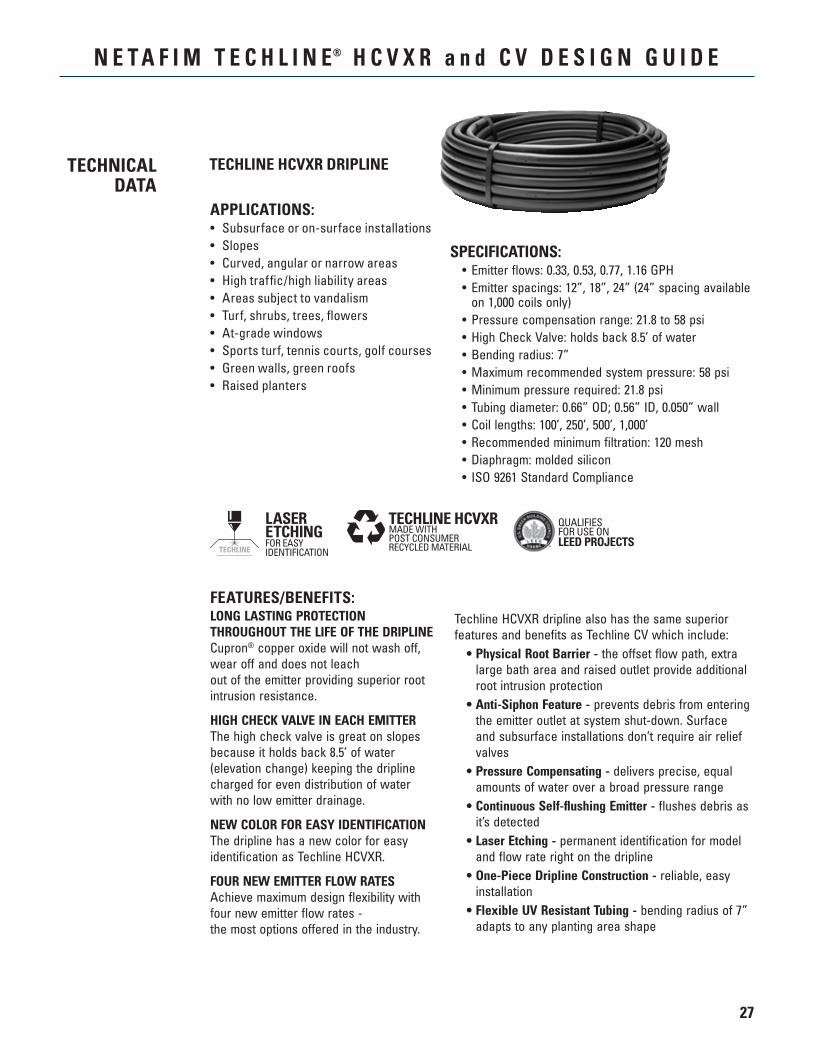
TECHLINE HCVXR DRIPLINETECHNICALDATA
SPECIFICATIONS: • Emitter flows: 0.33, 0.53, 0.77, 1.16 GPH • Emitter spacings: 12”, 18”, 24” (24” spacing available
on 1,000 coils only) • Pressure compensation range: 21.8 to 58 psi • High Check Valve: holds back 8.5’ of water • Bending radius: 7” • Maximum recommended system pressure: 58 psi • Minimum pressure required: 21.8 psi • Tubing diameter: 0.66” OD; 0.56” ID, 0.050” wall • Coil lengths: 100’, 250’, 500’, 1,000’ • Recommended minimum filtration: 120 mesh • Diaphragm: molded silicon • ISO 9261 Standard Compliance
FEATURES/BENEFITS:LONG LASTING PROTECTION THROUGHOUT THE LIFE OF THE DRIPLINECupron® copper oxide will not wash off, wear off and does not leach out of the emitter providing superior root intrusion resistance.
HIGH CHECK VALVE IN EACH EMITTERThe high check valve is great on slopes because it holds back 8.5’ of water (elevation change) keeping the dripline charged for even distribution of water with no low emitter drainage.
NEW COLOR FOR EASY IDENTIFICATIONThe dripline has a new color for easy identification as Techline HCVXR.
FOUR NEW EMITTER FLOW RATESAchieve maximum design flexibility with four new emitter flow rates - the most options offered in the industry.
Techline HCVXR dripline also has the same superior features and benefits as Techline CV which include: • Physical Root Barrier - the offset flow path, extra
large bath area and raised outlet provide additional root intrusion protection
• Anti-Siphon Feature - prevents debris from entering the emitter outlet at system shut-down. Surface and subsurface installations don’t require air relief valves
• Pressure Compensating - delivers precise, equal amounts of water over a broad pressure range
• Continuous Self-flushing Emitter - flushes debris as it’s detected
• Laser Etching - permanent identification for model and flow rate right on the dripline
• One-Piece Dripline Construction - reliable, easy installation
• Flexible UV Resistant Tubing - bending radius of 7” adapts to any planting area shape
TECHLINE HCVXR QUALIFIESFOR USE ONLEED PROJECTS
28
N E T A F I M T E C H L I N E® H C V X R a n d C V D E S I G N G U I D E
APPLICATIONS:• Subsurface or on-surface installations• Slopes• Curved, angular or narrow areas• High traffic/high liability areas• Areas subject to vandalism• High wind areas• Turf, shrubs, trees, flowers• At-grade windows• Sports turf, tennis courts, golf courses• Longer lateral runs• Green walls, green roofs• Raised planters
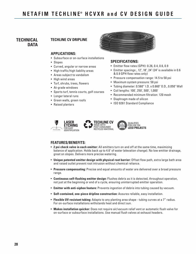
SPECIFICATIONS:• Emitter flow rates (GPH): 0.26, 0.4, 0.6, 0.9• Emitter spacings:, 12", 18", 24" (24" is available in 0.6
& 0.9 GPH flow rates only)• Pressure compensation range: 14.5 to 58 psi• Maximum system pressure: 58 psi• Tubing diameter: 0.560” I.D. x 0.660" O.D., 0.050" Wall• Coil lengths: 100', 250', 500', 1,000'• Recommended minimum filtration: 120 mesh• Diaphragm made of silicon• ISO 9261 Standard Compliance
FEATURES/BENEFITS:• 2 psi check valve in each emitter: All emitters turn on and off at the same time, maximizing
balance of application. Holds back up to 4.6’ of water (elevation change). No low emitter drainage, great on slopes. Delivers more precise watering.
• Unique patented emitter design with physical root barrier: Offset flow path, extra large bath area and raised outlet prevent root intrusion without chemical reliance.
• Pressure compensating: Precise and equal amounts of water are delivered over a broad pressure range.
• Continuous self-flushing emitter design: Flushes debris as it is detected, throughout operation, not just at the beginning or end of a cycle, ensuring uninterrupted emitter operation.
• Emitter with anti-siphon feature: Prevents ingestion of debris into tubing caused by vacuum.
• Self-contained, one-piece dripline construction: Assures reliable, easy installation.
• Flexible UV resistant tubing: Adapts to any planting area shape - tubing curves at a 7” radius. For on-surface installations withstands heat and direct sun.
• Makes installation quicker: Does not require air/vacuum relief vent or automatic flush valve for on-surface or subsurface installations. Use manual flush valves at exhaust headers.
TECHLINE CV DRIPLINETECHNICALDATA
QUALIFIESFOR USE ONLEED PROJECTS
29
N E T A F I M T E C H L I N E® H C V X R a n d C V D E S I G N G U I D E
TECHNICALDATA
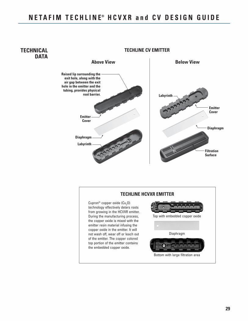
TECHLINE CV EMITTER
Above View Below View
Labyrinth
EmitterCover
Diaphragm
Raised lip surrounding the exit hole, along with the air gap between the exit
hole in the emitter and the tubing, provides physical
root barrier. Labyrinth
EmitterCover
Diaphragm
FiltrationSurface
Cupron® copper oxide (Cu2O) technology effectively deters roots from growing in the HCVXR emitter. During the manufacturing process, the copper oxide is mixed with the emitter resin material infusing the copper oxide in the emitter. It will not wash off, wear off or leach out of the emitter. The copper colored top portion of the emitter contains the embedded copper oxide.
Diaphragm
Bottom with large filtration area
Top with embedded copper oxide
TECHLINE HCVXR EMITTER
30
N E T A F I M T E C H L I N E® H C V X R a n d C V D E S I G N G U I D E
DESIGNFORMULAS
( )x
Emitter Flow Rate (GPH) ÷ 60
x60 (minutes)
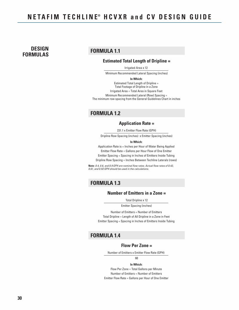
FORMULA 1.1
Irrigated Area x 12
Minimum Recommended Lateral Spacing (inches)
Estimated Total Length of Dripline =
In Which:Estimated Total Length of Dripline =Total Footage of Dripline in a Zone
Irrigated Area = Total Area in Square FeetMinimum Recommended Lateral (Row) Spacing =
The minimum row spacing from the General Guidelines Chart in inches
FORMULA 1.2
231.1 x Emitter Flow Rate (GPH)
Dripline Row Spacing (inches) x Emitter Spacing (inches)
Application Rate =
In Which:Application Rate is = Inches per Hour of Water Being Applied
Emitter Flow Rate = Gallons per Hour Flow of One EmitterEmitter Spacing = Spacing in Inches of Emitters Inside Tubing
Dripline Row Spacing = Inches Between Techline Laterals (rows)
In Which:Estimated Run Time = Estimated Number of minutes of run time for
a particular zone (based upon input data)Et = Evapotranspiration; The amount of water released from soil by
evaporation and transpiration from plants.Daily Et = Monthly Et divided by the number of days in the
associated month.Application Rate = Inches per hour of water being applied. This can be calculated by using Formula 1.2, or by referencing the
Application Rate Charts on pages 33 and 34.60 minutes = Conversion factor from hours to minutes
(60 minutes in one hour).
Note: 0.4, 0.6, and 0.9 GPH are nominal flow rates. Actual flow rates of 0.42, 0.61, and 0.92 GPH should be used in the calculations.
FORMULA 1.3
Total Dripline x 12
Emitter Spacing (inches)
Number of Emitters in a Zone =
Number of Emitters = Number of EmittersTotal Dripline = Length of All Dripline in a Zone in Feet
Emitter Spacing = Spacing in Inches of Emitters Inside Tubing
FORMULA 1.4
Number of Emitters x Emitter Flow Rate (GPH)
60
Flow Per Zone =
In Which:Flow Per Zone = Total Gallons per MinuteNumber of Emitters = Number of Emitters
Emitter Flow Rate = Gallons per Hour of One Emitter
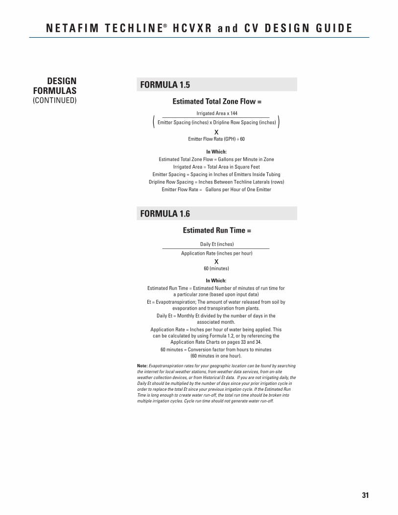
FORMULA 1.5
Irrigated Area x 144
Emitter Spacing (inches) x Dripline Row Spacing (inches)
Estimated Total Zone Flow =
In Which:Estimated Total Zone Flow = Gallons per Minute in Zone
Irrigated Area = Total Area in Square FeetEmitter Spacing = Spacing in Inches of Emitters Inside Tubing
Dripline Row Spacing = Inches Between Techline Laterals (rows)Emitter Flow Rate = Gallons per Hour of One Emitter
FORMULA 1.6
Daily Et (inches)
Application Rate (inches per hour)
Estimated Run Time =
Note: Evapotranspiration rates for your geographic location can be found by searching the internet for local weather stations, from weather data services, from on-site weather collection devices, or from Historical Et data. If you are not irrigating daily, the Daily Et should be multiplied by the number of days since your prior irrigation cycle in order to replace the total Et since your previous irrigation cycle. If the Estimated Run Time is long enough to create water run-off, the total run time should be broken into multiple irrigation cycles. Cycle run time should not generate water run-off.
31
N E T A F I M T E C H L I N E® H C V X R a n d C V D E S I G N G U I D E
DESIGNFORMULAS(CONTINUED)
( )x
Emitter Flow Rate (GPH) ÷ 60
x60 (minutes)
FORMULA 1.1
Irrigated Area x 12
Minimum Recommended Lateral Spacing (inches)
Estimated Total Length of Dripline =
In Which:Estimated Total Length of Dripline =Total Footage of Dripline in a Zone
Irrigated Area = Total Area in Square FeetMinimum Recommended Lateral (Row) Spacing =
The minimum row spacing from the General Guidelines Chart in inches
FORMULA 1.2
231.1 x Emitter Flow Rate (GPH)
Dripline Row Spacing (inches) x Emitter Spacing (inches)
Application Rate =
In Which:Application Rate is = Inches per Hour of Water Being Applied
Emitter Flow Rate = Gallons per Hour Flow of One EmitterEmitter Spacing = Spacing in Inches of Emitters Inside Tubing
Dripline Row Spacing = Inches Between Techline Laterals (rows)
In Which:Estimated Run Time = Estimated Number of minutes of run time for
a particular zone (based upon input data)Et = Evapotranspiration; The amount of water released from soil by
evaporation and transpiration from plants.Daily Et = Monthly Et divided by the number of days in the
associated month.Application Rate = Inches per hour of water being applied. This can be calculated by using Formula 1.2, or by referencing the
Application Rate Charts on pages 33 and 34.60 minutes = Conversion factor from hours to minutes
(60 minutes in one hour).
Note: 0.4, 0.6, and 0.9 GPH are nominal flow rates. Actual flow rates of 0.42, 0.61, and 0.92 GPH should be used in the calculations.
FORMULA 1.3
Total Dripline x 12
Emitter Spacing (inches)
Number of Emitters in a Zone =
Number of Emitters = Number of EmittersTotal Dripline = Length of All Dripline in a Zone in Feet
Emitter Spacing = Spacing in Inches of Emitters Inside Tubing
FORMULA 1.4
Number of Emitters x Emitter Flow Rate (GPH)
60
Flow Per Zone =
In Which:Flow Per Zone = Total Gallons per MinuteNumber of Emitters = Number of Emitters
Emitter Flow Rate = Gallons per Hour of One Emitter
FORMULA 1.5
Irrigated Area x 144
Emitter Spacing (inches) x Dripline Row Spacing (inches)
Estimated Total Zone Flow =
In Which:Estimated Total Zone Flow = Gallons per Minute in Zone
Irrigated Area = Total Area in Square FeetEmitter Spacing = Spacing in Inches of Emitters Inside Tubing
Dripline Row Spacing = Inches Between Techline Laterals (rows)Emitter Flow Rate = Gallons per Hour of One Emitter
FORMULA 1.6
Daily Et (inches)
Application Rate (inches per hour)
Estimated Run Time =
Note: Evapotranspiration rates for your geographic location can be found by searching the internet for local weather stations, from weather data services, from on-site weather collection devices, or from Historical Et data. If you are not irrigating daily, the Daily Et should be multiplied by the number of days since your prior irrigation cycle in order to replace the total Et since your previous irrigation cycle. If the Estimated Run Time is long enough to create water run-off, the total run time should be broken into multiple irrigation cycles. Cycle run time should not generate water run-off.
32
N E T A F I M T E C H L I N E® H C V X R a n d C V D E S I G N G U I D E
TECHNICALDATA
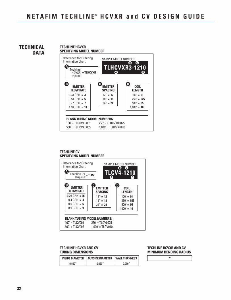
TECHLINE HCVXRSPECIFYING MODEL NUMBER
TLHCVXR3-1210
Reference for OrderingInformation Chart
TechlineHCVXR
Dripline= TLHCVXR
EMITTERFLOW RATE
EMITTERSPACING
COILLENGTH
C D
0.33 GPH0.53 GPH0.77 GPH1.16 GPH
= 3= 5= 7= 11
12”18”24”
= 12= 18= 24
100’250’500‘
1,000’
= 01= 025= 05= 10
D
B C
A
SAMPLE MODEL NUMBER
B
A
BLANK TUBING MODEL NUMBERS:100’ = TLHCVXR001 250’ = TLHCVXR0025500’ = TLHCVXR005 1,000’ = TLHCVXR010
TECHLINE CVSPECIFYING MODEL NUMBER
BLANK TUBING MODEL NUMBERS:100’ = TLCV001 250’ = TLCV0025500‘ = TLCV005 1,000’ = TLCV010
Reference for OrderingInformation Chart
Techline CVDripline = TLCV
EMITTERFLOW RATE
EMITTERSPACING
COILLENGTH
C D
0.26 GPH0.4 GPH0.6 GPH0.9 GPH
= 26= 4= 6= 9
12”18”24”
= 12= 18= 24
100’250’500‘
1,000’
= 01= 025= 05= 10
D
B C
A
SAMPLE MODEL NUMBER
TLCV4-1210
B
A
TECHLINE HCVXR AND CVTUBING DIMENSIONS
INSIDE DIAMETER
0.560” 0.660” 0.050”
OUTSIDE DIAMETER WALL THICKNESS
TECHLINE HCVXR AND CVMINIMUM BENDING RADIUS
7”
33
N E T A F I M T E C H L I N E® H C V X R a n d C V D E S I G N G U I D E
TECHNICALDATA
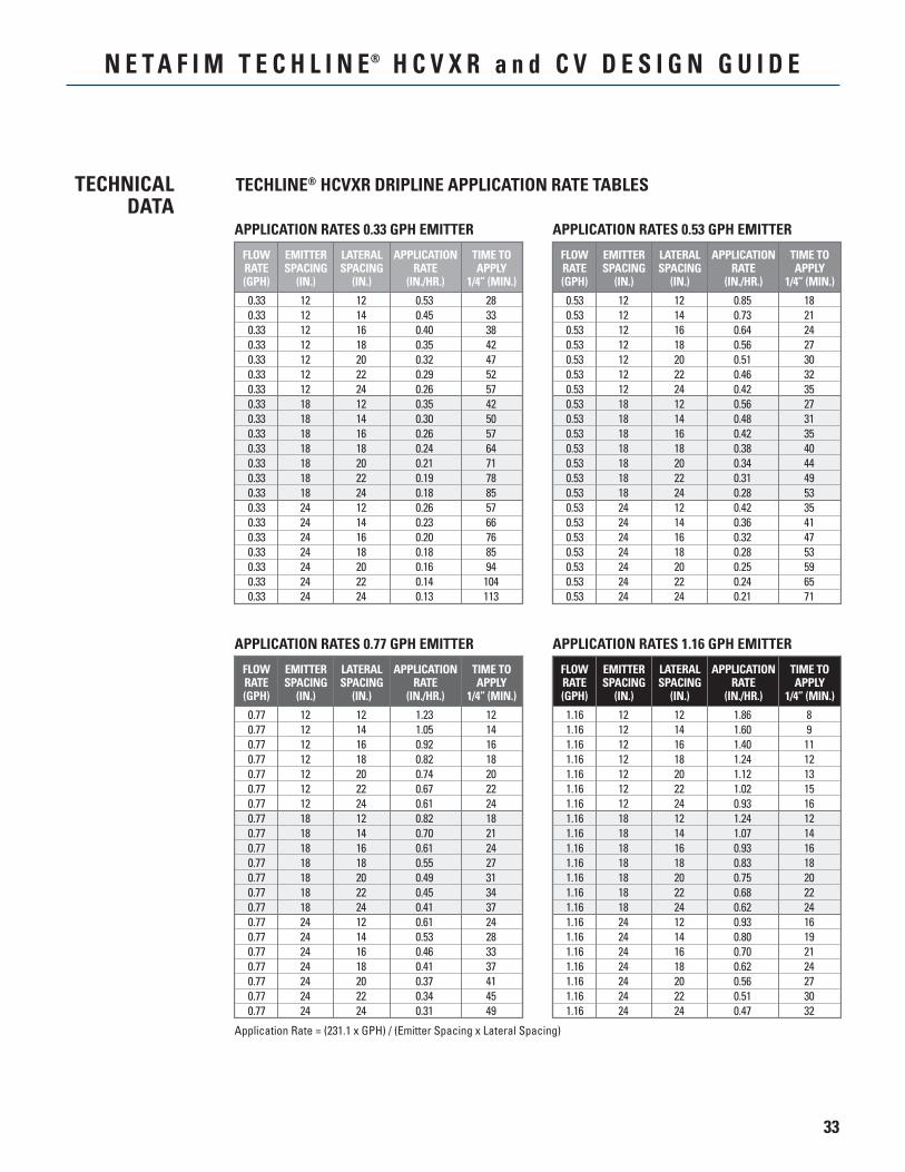
APPLICATION RATES 0.33 GPH EMITTER
APPLICATIONRATE
(IN./HR.)
TIME TOAPPLY
1/4” (MIN.)
FLOWRATE(GPH)
EMITTERSPACING
(IN.)
LATERALSPACING
(IN.)
0.330.330.330.330.330.330.330.330.330.330.330.330.330.330.330.330.330.330.330.330.33
121212121212121818181818181824242424242424
121416182022241214161820222412141618202224
0.530.450.400.350.320.290.260.350.300.260.240.210.190.180.260.230.200.180.160.140.13
28333842475257425057647178855766768594104113
APPLICATION RATES 0.53 GPH EMITTER
APPLICATIONRATE
(IN./HR.)
TIME TOAPPLY
1/4” (MIN.)
FLOWRATE(GPH)
EMITTERSPACING
(IN.)
LATERALSPACING
(IN.)
0.530.530.530.530.530.530.530.530.530.530.530.530.530.530.530.530.530.530.530.530.53
121212121212121818181818181824242424242424
121416182022241214161820222412141618202224
0.850.730.640.560.510.460.420.560.480.420.380.340.310.280.420.360.320.280.250.240.21
182124273032352731354044495335414753596571
APPLICATION RATES 0.77 GPH EMITTER
Application Rate = (231.1 x GPH) / (Emitter Spacing x Lateral Spacing)
APPLICATIONRATE
(IN./HR.)
TIME TOAPPLY
1/4” (MIN.)
FLOWRATE(GPH)
EMITTERSPACING
(IN.)
LATERALSPACING
(IN.)
0.770.770.770.770.770.770.770.770.770.770.770.770.770.770.770.770.770.770.770.770.77
121212121212121818181818181824242424242424
121416182022241214161820222412141618202224
1.231.050.920.820.740.670.610.820.700.610.550.490.450.410.610.530.460.410.370.340.31
121416182022241821242731343724283337414549
APPLICATION RATES 1.16 GPH EMITTER
APPLICATIONRATE
(IN./HR.)
TIME TOAPPLY
1/4” (MIN.)
FLOWRATE(GPH)
EMITTERSPACING
(IN.)
LATERALSPACING
(IN.)
1.161.161.161.161.161.161.161.161.161.161.161.161.161.161.161.161.161.161.161.161.16
121212121212121818181818181824242424242424
121416182022241214161820222412141618202224
1.861.601.401.241.121.020.931.241.070.930.830.750.680.620.930.800.700.620.560.510.47
8911121315161214161820222416192124273032
TECHLINE® HCVXR DRIPLINE APPLICATION RATE TABLES
34
N E T A F I M T E C H L I N E® H C V X R a n d C V D E S I G N G U I D E
TECHNICALDATA
TECHLINE® CV DRIPLINE APPLICATION RATE TABLES
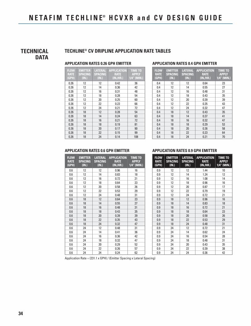
APPLICATION RATES 0.26 GPH EMITTER
APPLICATIONRATE
(IN./HR.)
TIME TOAPPLY
1/4” (MIN.)
FLOWRATE(GPH)
EMITTERSPACING
(IN.)
LATERALSPACING
(IN.)
0.260.260.260.260.260.260.260.260.260.260.260.260.260.26
1212121212121218181818181818
1214161820222412141618202224
0.420.360.310.280.250.230.210.280.240.210.190.170.150.14
36424854606672546372819099108
APPLICATION RATES 0.4 GPH EMITTER
APPLICATIONRATE
(IN./HR.)
TIME TOAPPLY
1/4” (MIN.)
FLOWRATE(GPH)
EMITTERSPACING
(IN.)
LATERALSPACING
(IN.)
0.40.40.40.40.40.40.40.40.40.40.40.40.40.4
1212121212121218181818181818
1214161820222412141618202224
0.640.550.480.430.390.350.320.430.370.320.290.260.230.21
2327313539434735414753586470
APPLICATION RATES 0.6 GPH EMITTER
Application Rate = (231.1 x GPH) / (Emitter Spacing x Lateral Spacing)
APPLICATIONRATE
(IN./HR.)
TIME TOAPPLY
1/4” (MIN.)
FLOWRATE(GPH)
EMITTERSPACING
(IN.)
LATERALSPACING
(IN.)
0.60.60.60.60.60.60.60.60.60.60.60.60.60.60.60.60.60.60.60.60.6
121212121212121818181818181824242424242424
121416182022241214161820222412141618202224
0.960.830.720.640.580.530.480.640.550.480.430.390.350.320.480.410.360.320.290.260.24
161821232629312327313539434731364247525762
APPLICATION RATES 0.9 GPH EMITTER
APPLICATIONRATE
(IN./HR.)
TIME TOAPPLY
1/4” (MIN.)
FLOWRATE(GPH)
EMITTERSPACING
(IN.)
LATERALSPACING
(IN.)
0.90.90.90.90.90.90.90.90.90.90.90.90.90.90.90.90.90.90.90.90.9
121212121212121818181818181824242424242424
121416182022241214161820222412141618202224
1.441.241.080.960.870.790.720.960.830.720.640.580.530.480.720.620.540.480.430.390.36
101214161719211618212326293121242831353842
35
N E T A F I M T E C H L I N E® H C V X R a n d C V D E S I G N G U I D E
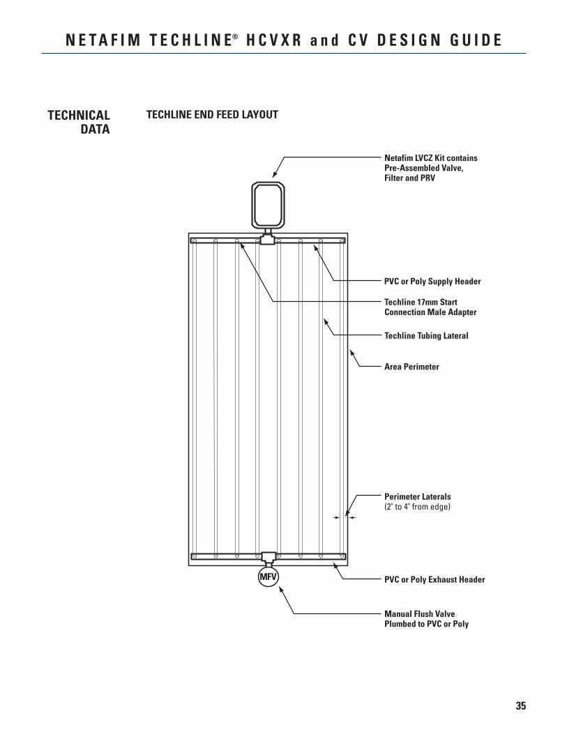
Netafim LVCZ Kit containsPre-Assembled Valve,Filter and PRV
Perimeter Laterals(2" to 4" from edge)
PVC or Poly Supply Header
Techline Tubing Lateral
Area Perimeter
Manual Flush ValvePlumbed to PVC or Poly
PVC or Poly Exhaust HeaderMFV
Techline 17mm StartConnection Male Adapter
TECHLINE END FEED LAYOUTTECHNICALDATA
36
N E T A F I M T E C H L I N E® H C V X R a n d C V D E S I G N G U I D E
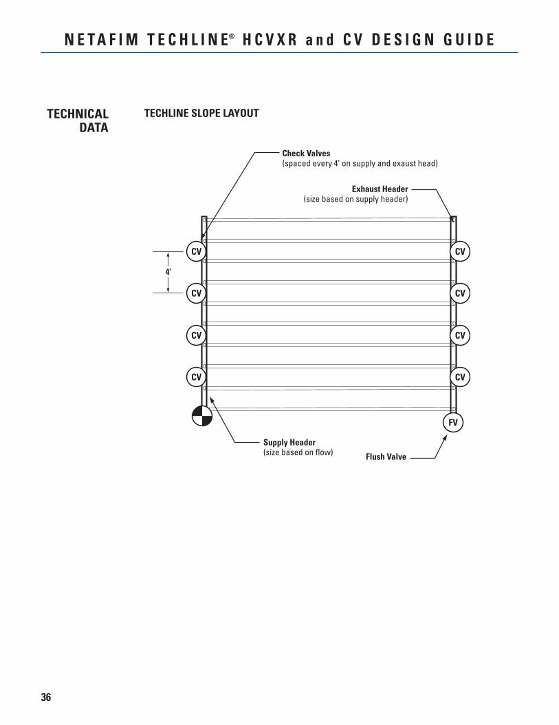
TECHLINE SLOPE LAYOUTTECHNICALDATA
CV
CV
CV
CV
CV
CV
CV
CV
FV
Check Valves(spaced every 4’ on supply and exaust head)
Exhaust Header(size based on supply header)
Supply Header(size based on flow) Flush Valve
4’
37
N E T A F I M T E C H L I N E® H C V X R a n d C V D E S I G N G U I D E
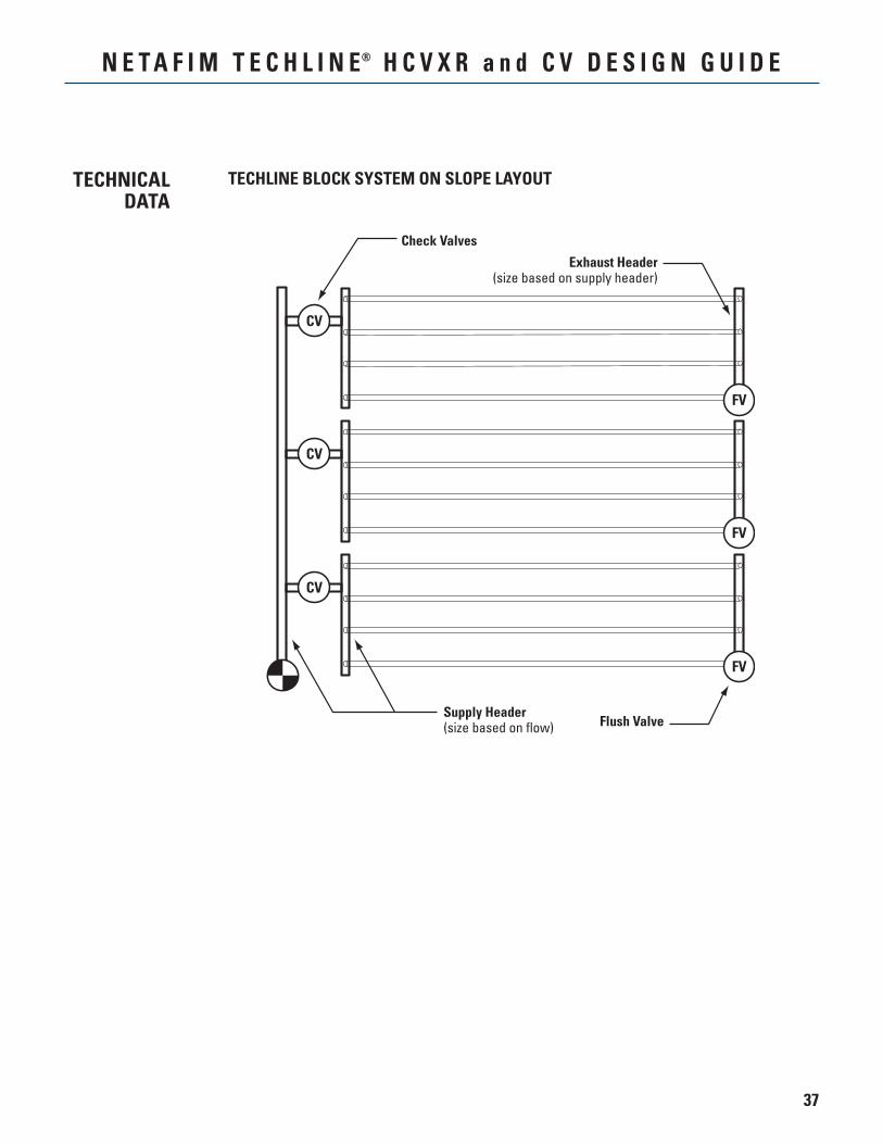
TECHLINE BLOCK SYSTEM ON SLOPE LAYOUTTECHNICALDATA
FV
CV
FV
CV
FV
CV
Check Valves
Exhaust Header(size based on supply header)
Supply Header(size based on flow) Flush Valve
38
N E T A F I M T E C H L I N E® H C V X R a n d C V D E S I G N G U I D E
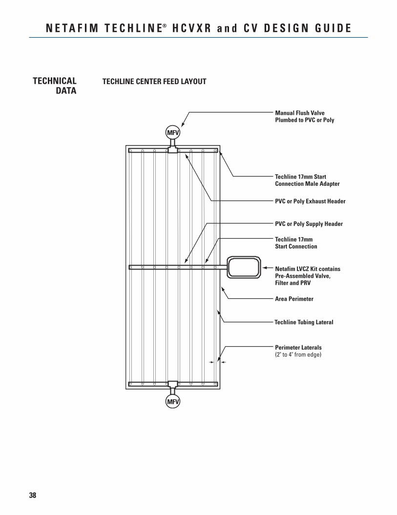
TECHLINE CENTER FEED LAYOUT
Manual Flush ValvePlumbed to PVC or Poly
Perimeter Laterals(2" to 4" from edge)
Techline 17mmStart Connection
PVC or Poly Supply Header
Techline 17mm StartConnection Male Adapter
Techline Tubing Lateral
Area Perimeter
PVC or Poly Exhaust Header
Netafim LVCZ Kit containsPre-Assembled Valve,Filter and PRV
MFV
MFV
TECHNICALDATA
39
N E T A F I M T E C H L I N E® H C V X R a n d C V D E S I G N G U I D E
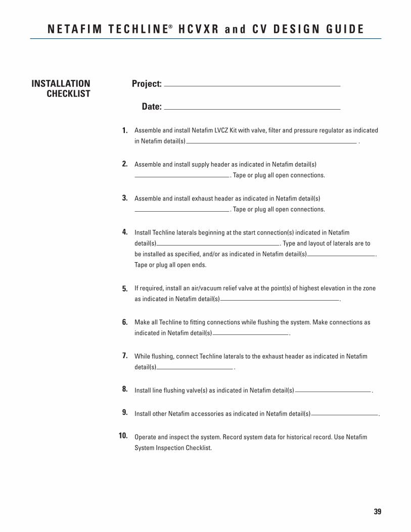
Assemble and install Netafim LVCZ Kit with valve, filter and pressure regulator as indicated
in Netafim detail(s) .
Assemble and install supply header as indicated in Netafim detail(s)
. Tape or plug all open connections.
Assemble and install exhaust header as indicated in Netafim detail(s)
. Tape or plug all open connections.
Install Techline laterals beginning at the start connection(s) indicated in Netafim
detail(s) . Type and layout of laterals are to
be installed as specified, and/or as indicated in Netafim detail(s) .
Tape or plug all open ends.
If required, install an air/vacuum relief valve at the point(s) of highest elevation in the zone
as indicated in Netafim detail(s) .
Make all Techline to fitting connections while flushing the system. Make connections as
indicated in Netafim detail(s) .
While flushing, connect Techline laterals to the exhaust header as indicated in Netafim
detail(s) .
Install line flushing valve(s) as indicated in Netafim detail(s) .
Install other Netafim accessories as indicated in Netafim detail(s) .
Operate and inspect the system. Record system data for historical record. Use Netafim
System Inspection Checklist.
Project:
Date:
1.
2.
3.
4.
5.
6.
7.
8.
9.
10.
INSTALLATIONCHECKLIST
40
N E T A F I M T E C H L I N E® H C V X R a n d C V D E S I G N G U I D E
SYSTEMINSPECTIONCHECK LIST
Project:
Date:
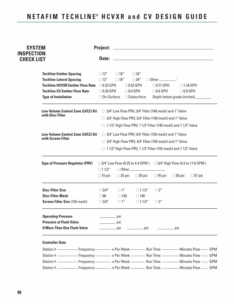
Techline Emitter Spacing 12” 18” 24”Techline Lateral Spacing 12” 18” 24” Other "Techline HCVXR Emitter Flow Rate 0.33 GPH 0.53 GPH 0.77 GPH 1.16 GPHTechline CV Emitter Flow Rate 0.26 GPH 0.4 GPH 0.6 GPH 0.9 GPHType of Installation On-Surface Subsurface Depth below grade (inches)
Station # Frequency x Per Week Run Time: Minutes Flow GPM
Station # Frequency x Per Week Run Time: Minutes Flow GPM
Station # Frequency x Per Week Run Time: Minutes Flow GPM
Station # Frequency x Per Week Run Time: Minutes Flow GPM
Controller Data
Operating Pressure psiPressure at Flush Valve psiIf More Than One Flush Valve psi psi psi
Type of Pressure Regulator (PRV) 3/4" Low Flow (0.25 to 4.4 GPM ) 3/4" High Flow (4.5 to 17.6 GPM )
1 1/2” Other
15 psi 25 psi 35 psi 45 psi 50 psi 57 psi
Disc Filter Size 3/4” 1” 1 1/2” 2”Disc Filter Mesh 80 120 140Screen Filter Size (155 mesh) 3/4” 1” 1 1/2” 2”
Low Volume Control Zone (LVCZ) Kit 3/4" Low Flow PRV, 3/4" Filter (140 mesh) and 1" Valvewith Disc Filter
3/4" High Flow PRV, 3/4" Filter (140 mesh) and 1" Valve
1 1/2" High Flow PRV, 1 1/2" Filter (140 mesh) and 1 1/2" Valve
Low Volume Control Zone (LVCZ) Kit 3/4" Low Flow PRV, 3/4" Filter (155 mesh) and 1" Valvewith Screen Filter
3/4" High Flow PRV, 3/4" Filter (155 mesh) and 1" Valve
1 1/2" High Flow PRV, 1 1/2" Filter (155 mesh) and 1 1/2" Valve
41
N E T A F I M T E C H L I N E® H C V X R a n d C V D E S I G N G U I D E
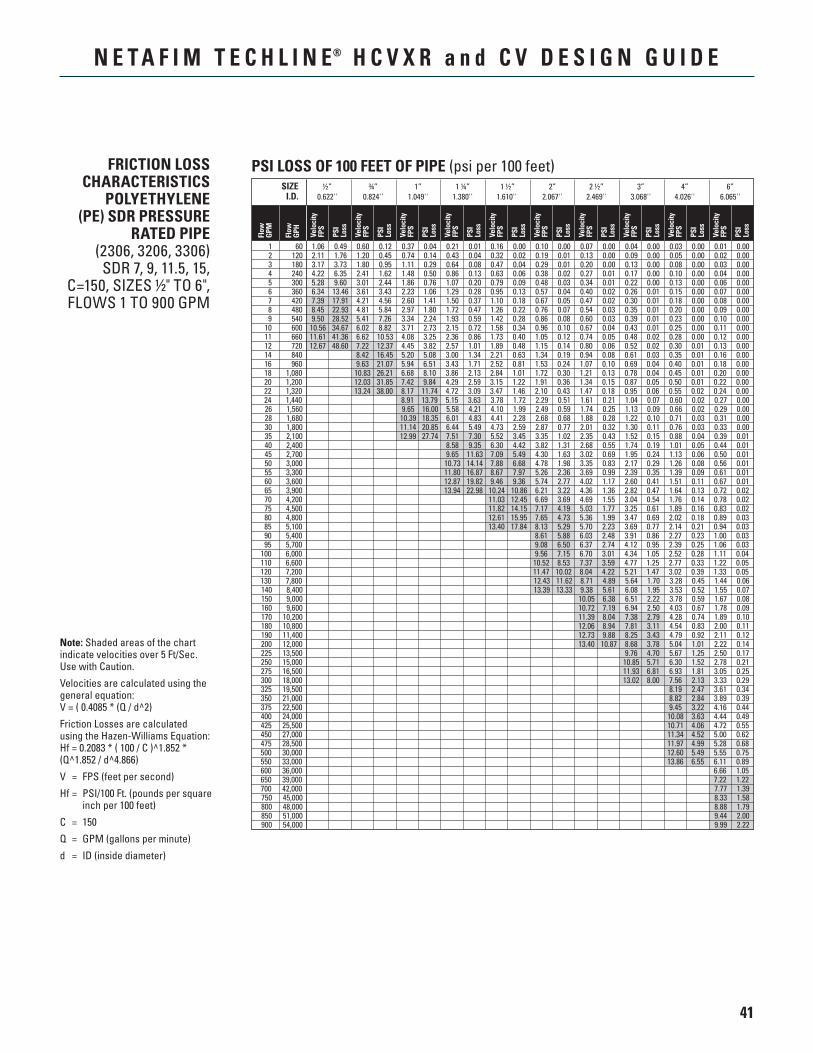
FRICTION LOSS CHARACTERISTICS
POLYETHYLENE (PE) SDR PRESSURE
RATED PIPE(2306, 3206, 3306)
SDR 7, 9, 11.5, 15, C=150, SIZES ½" TO 6", FLOWS 1 TO 900 GPM
Note: Shaded areas of the chart indicate velocities over 5 Ft/Sec. Use with Caution.
Velocities are calculated using the general equation: V = ( 0.4085 * (Q / d^2)
Friction Losses are calculated using the Hazen-Williams Equation: Hf = 0.2083 * ( 100 / C )^1.852 * (Q^1.852 / d^4.866)
V = FPS (feet per second)
Hf = PSI/100 Ft. (pounds per square inch per 100 feet)
C = 150
Q = GPM (gallons per minute)
d = ID (inside diameter)
PSI LOSS OF 100 FEET OF PIPE (psi per 100 feet)
Flow
GPM
Flow
GPH
Velo
city
FPS
SIZE ½” ¾” 1” 1 ¼” 1 ½” 2” 2 ½” 3” 4” 6” I.D. 0.622'' 0.824'' 1.049'' 1.380'' 1.610'' 2.067'' 2.469'' 3.068'' 4.026'' 6.065''
PSI
Loss
Velo
city
FPS
PSI
Loss
Velo
city
FPS
PSI
Loss
Velo
city
FPS
PSI
Loss
Velo
city
FPS
PSI
Loss
Velo
city
FPS
PSI
Loss
Velo
city
FPS
PSI
Loss
Velo
city
FPS
PSI
Loss
Velo
city
FPS
PSI
Loss
Velo
city
FPS
PSI
Loss
1 60 1.06 0.49 0.60 0.12 0.37 0.04 0.21 0.01 0.16 0.00 0.10 0.00 0.07 0.00 0.04 0.00 0.03 0.00 0.01 0.00 2 120 2.11 1.76 1.20 0.45 0.74 0.14 0.43 0.04 0.32 0.02 0.19 0.01 0.13 0.00 0.09 0.00 0.05 0.00 0.02 0.00 3 180 3.17 3.73 1.80 0.95 1.11 0.29 0.64 0.08 0.47 0.04 0.29 0.01 0.20 0.00 0.13 0.00 0.08 0.00 0.03 0.00 4 240 4.22 6.35 2.41 1.62 1.48 0.50 0.86 0.13 0.63 0.06 0.38 0.02 0.27 0.01 0.17 0.00 0.10 0.00 0.04 0.00 5 300 5.28 9.60 3.01 2.44 1.86 0.76 1.07 0.20 0.79 0.09 0.48 0.03 0.34 0.01 0.22 0.00 0.13 0.00 0.06 0.00 6 360 6.34 13.46 3.61 3.43 2.23 1.06 1.29 0.28 0.95 0.13 0.57 0.04 0.40 0.02 0.26 0.01 0.15 0.00 0.07 0.00 7 420 7.39 17.91 4.21 4.56 2.60 1.41 1.50 0.37 1.10 0.18 0.67 0.05 0.47 0.02 0.30 0.01 0.18 0.00 0.08 0.00 8 480 8.45 22.93 4.81 5.84 2.97 1.80 1.72 0.47 1.26 0.22 0.76 0.07 0.54 0.03 0.35 0.01 0.20 0.00 0.09 0.00 9 540 9.50 28.52 5.41 7.26 3.34 2.24 1.93 0.59 1.42 0.28 0.86 0.08 0.60 0.03 0.39 0.01 0.23 0.00 0.10 0.00 10 600 10.56 34.67 6.02 8.82 3.71 2.73 2.15 0.72 1.58 0.34 0.96 0.10 0.67 0.04 0.43 0.01 0.25 0.00 0.11 0.00 11 660 11.61 41.36 6.62 10.53 4.08 3.25 2.36 0.86 1.73 0.40 1.05 0.12 0.74 0.05 0.48 0.02 0.28 0.00 0.12 0.00 12 720 12.67 48.60 7.22 12.37 4.45 3.82 2.57 1.01 1.89 0.48 1.15 0.14 0.80 0.06 0.52 0.02 0.30 0.01 0.13 0.00 14 840 8.42 16.45 5.20 5.08 3.00 1.34 2.21 0.63 1.34 0.19 0.94 0.08 0.61 0.03 0.35 0.01 0.16 0.00 16 960 9.63 21.07 5.94 6.51 3.43 1.71 2.52 0.81 1.53 0.24 1.07 0.10 0.69 0.04 0.40 0.01 0.18 0.00 18 1,080 10.83 26.21 6.68 8.10 3.86 2.13 2.84 1.01 1.72 0.30 1.21 0.13 0.78 0.04 0.45 0.01 0.20 0.00 20 1,200 12.03 31.85 7.42 9.84 4.29 2.59 3.15 1.22 1.91 0.36 1.34 0.15 0.87 0.05 0.50 0.01 0.22 0.00 22 1,320 13.24 38.00 8.17 11.74 4.72 3.09 3.47 1.46 2.10 0.43 1.47 0.18 0.95 0.06 0.55 0.02 0.24 0.00 24 1,440 8.91 13.79 5.15 3.63 3.78 1.72 2.29 0.51 1.61 0.21 1.04 0.07 0.60 0.02 0.27 0.00 26 1,560 9.65 16.00 5.58 4.21 4.10 1.99 2.49 0.59 1.74 0.25 1.13 0.09 0.66 0.02 0.29 0.00 28 1,680 10.39 18.35 6.01 4.83 4.41 2.28 2.68 0.68 1.88 0.28 1.22 0.10 0.71 0.03 0.31 0.00 30 1,800 11.14 20.85 6.44 5.49 4.73 2.59 2.87 0.77 2.01 0.32 1.30 0.11 0.76 0.03 0.33 0.00 35 2,100 12.99 27.74 7.51 7.30 5.52 3.45 3.35 1.02 2.35 0.43 1.52 0.15 0.88 0.04 0.39 0.01 40 2,400 8.58 9.35 6.30 4.42 3.82 1.31 2.68 0.55 1.74 0.19 1.01 0.05 0.44 0.01 45 2,700 9.65 11.63 7.09 5.49 4.30 1.63 3.02 0.69 1.95 0.24 1.13 0.06 0.50 0.01 50 3,000 10.73 14.14 7.88 6.68 4.78 1.98 3.35 0.83 2.17 0.29 1.26 0.08 0.56 0.01 55 3,300 11.80 16.87 8.67 7.97 5.26 2.36 3.69 0.99 2.39 0.35 1.39 0.09 0.61 0.01 60 3,600 12.87 19.82 9.46 9.36 5.74 2.77 4.02 1.17 2.60 0.41 1.51 0.11 0.67 0.01 65 3,900 13.94 22.98 10.24 10.86 6.21 3.22 4.36 1.36 2.82 0.47 1.64 0.13 0.72 0.02 70 4,200 11.03 12.45 6.69 3.69 4.69 1.55 3.04 0.54 1.76 0.14 0.78 0.02 75 4,500 11.82 14.15 7.17 4.19 5.03 1.77 3.25 0.61 1.89 0.16 0.83 0.02 80 4,800 12.61 15.95 7.65 4.73 5.36 1.99 3.47 0.69 2.02 0.18 0.89 0.03 85 5,100 13.40 17.84 8.13 5.29 5.70 2.23 3.69 0.77 2.14 0.21 0.94 0.03 90 5,400 8.61 5.88 6.03 2.48 3.91 0.86 2.27 0.23 1.00 0.03 95 5,700 9.08 6.50 6.37 2.74 4.12 0.95 2.39 0.25 1.06 0.03 100 6,000 9.56 7.15 6.70 3.01 4.34 1.05 2.52 0.28 1.11 0.04 110 6,600 10.52 8.53 7.37 3.59 4.77 1.25 2.77 0.33 1.22 0.05 120 7,200 11.47 10.02 8.04 4.22 5.21 1.47 3.02 0.39 1.33 0.05 130 7,800 12.43 11.62 8.71 4.89 5.64 1.70 3.28 0.45 1.44 0.06 140 8,400 13.39 13.33 9.38 5.61 6.08 1.95 3.53 0.52 1.55 0.07 150 9,000 10.05 6.38 6.51 2.22 3.78 0.59 1.67 0.08 160 9,600 10.72 7.19 6.94 2.50 4.03 0.67 1.78 0.09 170 10,200 11.39 8.04 7.38 2.79 4.28 0.74 1.89 0.10 180 10,800 12.06 8.94 7.81 3.11 4.54 0.83 2.00 0.11 190 11,400 12.73 9.88 8.25 3.43 4.79 0.92 2.11 0.12 200 12,000 13.40 10.87 8.68 3.78 5.04 1.01 2.22 0.14 225 13,500 9.76 4.70 5.67 1.25 2.50 0.17 250 15,000 10.85 5.71 6.30 1.52 2.78 0.21 275 16,500 11.93 6.81 6.93 1.81 3.05 0.25 300 18,000 13.02 8.00 7.56 2.13 3.33 0.29 325 19,500 8.19 2.47 3.61 0.34 350 21,000 8.82 2.84 3.89 0.39 375 22,500 9.45 3.22 4.16 0.44 400 24,000 10.08 3.63 4.44 0.49 425 25,500 10.71 4.06 4.72 0.55 450 27,000 11.34 4.52 5.00 0.62 475 28,500 11.97 4.99 5.28 0.68 500 30,000 12.60 5.49 5.55 0.75 550 33,000 13.86 6.55 6.11 0.89 600 36,000 6.66 1.05 650 39,000 7.22 1.22 700 42,000 7.77 1.39 750 45,000 8.33 1.58 800 48,000 8.88 1.79 850 51,000 9.44 2.00 900 54,000 9.99 2.22
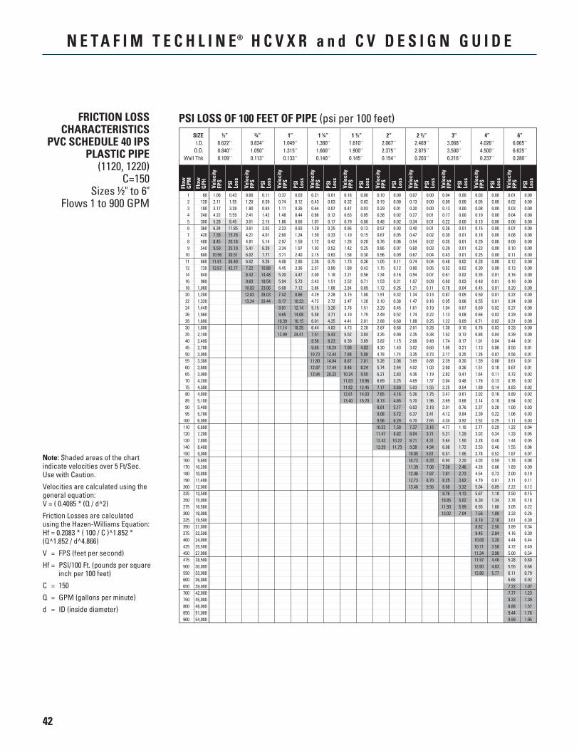
42
N E T A F I M T E C H L I N E® H C V X R a n d C V D E S I G N G U I D E
FRICTION LOSS CHARACTERISTICS
PVC SCHEDULE 40 IPS PLASTIC PIPE
(1120, 1220)C=150
Sizes ½" to 6"Flows 1 to 900 GPM
Note: Shaded areas of the chart indicate velocities over 5 Ft/Sec. Use with Caution.
Velocities are calculated using the general equation: V = ( 0.4085 * (Q / d^2)
Friction Losses are calculated using the Hazen-Williams Equation: Hf = 0.2083 * ( 100 / C )^1.852 * (Q^1.852 / d^4.866)
V = FPS (feet per second)
Hf = PSI/100 Ft. (pounds per square inch per 100 feet)
C = 150
Q = GPM (gallons per minute)
d = ID (inside diameter)
PSI LOSS OF 100 FEET OF PIPE (psi per 100 feet) SIZE ½” ¾” 1” 1 ¼” 1 ½” 2” 2 ½” 3” 4” 6” I.D. 0.622'' 0.824'' 1.049'' 1.380'' 1.610'' 2.067'' 2.469'' 3.068'' 4.026'' 6.065'' O.D. 0.840'' 1.050'' 1.315'' 1.660'' 1.900'' 2.375'' 2.875'' 3.500'' 4.500'' 6.625'' Wall Thk 0.109'' 0.113'' 0.133'' 0.140'' 0.145'' 0.154'' 0.203'' 0.216'' 0.237'' 0.280''
Flow
GPM
Flow
GPH Ve
loci
tyFP
S
PSI
Loss
Velo
city
FPS
PSI
Loss
Velo
city
FPS
PSI
Loss
Velo
city
FPS
PSI
Loss
Velo
city
FPS
PSI
Loss
Velo
city
FPS
PSI
Loss
Velo
city
FPS
PSI
Loss
Velo
city
FPS
PSI
Loss
Velo
city
FPS
PSI
Loss
Velo
city
FPS
PSI
Loss
1 60 1.06 0.43 0.60 0.11 0.37 0.03 0.21 0.01 0.16 0.00 0.10 0.00 0.07 0.00 0.04 0.00 0.03 0.00 0.01 0.00 2 120 2.11 1.55 1.20 0.39 0.74 0.12 0.43 0.03 0.32 0.02 0.19 0.00 0.13 0.00 0.09 0.00 0.05 0.00 0.02 0.00 3 180 3.17 3.28 1.80 0.84 1.11 0.26 0.64 0.07 0.47 0.03 0.29 0.01 0.20 0.00 0.13 0.00 0.08 0.00 0.03 0.00 4 240 4.22 5.59 2.41 1.42 1.48 0.44 0.86 0.12 0.63 0.05 0.38 0.02 0.27 0.01 0.17 0.00 0.10 0.00 0.04 0.00 5 300 5.28 8.45 3.01 2.15 1.86 0.66 1.07 0.17 0.79 0.08 0.48 0.02 0.34 0.01 0.22 0.00 0.13 0.00 0.06 0.00 6 360 6.34 11.85 3.61 3.02 2.23 0.93 1.29 0.25 0.95 0.12 0.57 0.03 0.40 0.01 0.26 0.01 0.15 0.00 0.07 0.00 7 420 7.39 15.76 4.21 4.01 2.60 1.24 1.50 0.33 1.10 0.15 0.67 0.05 0.47 0.02 0.30 0.01 0.18 0.00 0.08 0.00 8 480 8.45 20.18 4.81 5.14 2.97 1.59 1.72 0.42 1.26 0.20 0.76 0.06 0.54 0.02 0.35 0.01 0.20 0.00 0.09 0.00 9 540 9.50 25.10 5.41 6.39 3.34 1.97 1.93 0.52 1.42 0.25 0.86 0.07 0.60 0.03 0.39 0.01 0.23 0.00 0.10 0.00 10 600 10.56 30.51 6.02 7.77 3.71 2.40 2.15 0.63 1.58 0.30 0.96 0.09 0.67 0.04 0.43 0.01 0.25 0.00 0.11 0.00 11 660 11.61 36.40 6.62 9.26 4.08 2.86 2.36 0.75 1.73 0.36 1.05 0.11 0.74 0.04 0.48 0.02 0.28 0.00 0.12 0.00 12 720 12.67 42.77 7.22 10.88 4.45 3.36 2.57 0.89 1.89 0.42 1.15 0.12 0.80 0.05 0.52 0.02 0.30 0.00 0.13 0.00 14 840 8.42 14.48 5.20 4.47 3.00 1.18 2.21 0.56 1.34 0.16 0.94 0.07 0.61 0.02 0.35 0.01 0.16 0.00 16 960 9.63 18.54 5.94 5.73 3.43 1.51 2.52 0.71 1.53 0.21 1.07 0.09 0.69 0.03 0.40 0.01 0.18 0.00 18 1,080 10.83 23.06 6.68 7.12 3.86 1.88 2.84 0.89 1.72 0.26 1.21 0.11 0.78 0.04 0.45 0.01 0.20 0.00 20 1,200 12.03 28.03 7.42 8.66 4.29 2.28 3.15 1.08 1.91 0.32 1.34 0.13 0.87 0.05 0.50 0.01 0.22 0.00 22 1,320 13.24 33.44 8.17 10.33 4.72 2.72 3.47 1.28 2.10 0.38 1.47 0.16 0.95 0.06 0.55 0.01 0.24 0.00 24 1,440 8.91 12.14 5.15 3.20 3.78 1.51 2.29 0.45 1.61 0.19 1.04 0.07 0.60 0.02 0.27 0.00 26 1,560 9.65 14.08 5.58 3.71 4.10 1.75 2.49 0.52 1.74 0.22 1.13 0.08 0.66 0.02 0.29 0.00 28 1,680 10.39 16.15 6.01 4.25 4.41 2.01 2.68 0.60 1.88 0.25 1.22 0.09 0.71 0.02 0.31 0.00 30 1,800 11.14 18.35 6.44 4.83 4.73 2.28 2.87 0.68 2.01 0.28 1.30 0.10 0.76 0.03 0.33 0.00 35 2,100 12.99 24.41 7.51 6.43 5.52 3.04 3.35 0.90 2.35 0.38 1.52 0.13 0.88 0.04 0.39 0.00 40 2,400 8.58 8.23 6.30 3.89 3.82 1.15 2.68 0.49 1.74 0.17 1.01 0.04 0.44 0.01 45 2,700 9.65 10.24 7.09 4.83 4.30 1.43 3.02 0.60 1.95 0.21 1.13 0.06 0.50 0.01 50 3,000 10.73 12.44 7.88 5.88 4.78 1.74 3.35 0.73 2.17 0.25 1.26 0.07 0.56 0.01 55 3,300 11.80 14.84 8.67 7.01 5.26 2.08 3.69 0.88 2.39 0.30 1.39 0.08 0.61 0.01 60 3,600 12.87 17.44 9.46 8.24 5.74 2.44 4.02 1.03 2.60 0.36 1.51 0.10 0.67 0.01 65 3,900 13.94 20.23 10.24 9.55 6.21 2.83 4.36 1.19 2.82 0.41 1.64 0.11 0.72 0.02 70 4,200 11.03 10.96 6.69 3.25 4.69 1.37 3.04 0.48 1.76 0.13 0.78 0.02 75 4,500 11.82 12.45 7.17 3.69 5.03 1.55 3.25 0.54 1.89 0.14 0.83 0.02 80 4,800 12.61 14.03 7.65 4.16 5.36 1.75 3.47 0.61 2.02 0.16 0.89 0.02 85 5,100 13.40 15.70 8.13 4.65 5.70 1.96 3.69 0.68 2.14 0.18 0.94 0.02 90 5,400 8.61 5.17 6.03 2.18 3.91 0.76 2.27 0.20 1.00 0.03 95 5,700 9.08 5.72 6.37 2.41 4.12 0.84 2.39 0.22 1.06 0.03 100 6,000 9.56 6.29 6.70 2.65 4.34 0.92 2.52 0.25 1.11 0.03 110 6,600 10.52 7.50 7.37 3.16 4.77 1.10 2.77 0.29 1.22 0.04 120 7,200 11.47 8.82 8.04 3.71 5.21 1.29 3.02 0.34 1.33 0.05 130 7,800 12.43 10.22 8.71 4.31 5.64 1.50 3.28 0.40 1.44 0.05 140 8,400 13.39 11.73 9.38 4.94 6.08 1.72 3.53 0.46 1.55 0.06 150 9,000 10.05 5.61 6.51 1.95 3.78 0.52 1.67 0.07 160 9,600 10.72 6.33 6.94 2.20 4.03 0.59 1.78 0.08 170 10,200 11.39 7.08 7.38 2.46 4.28 0.66 1.89 0.09 180 10,800 12.06 7.87 7.81 2.73 4.54 0.73 2.00 0.10 190 11,400 12.73 8.70 8.25 3.02 4.79 0.81 2.11 0.11 200 12,000 13.40 9.56 8.68 3.32 5.04 0.89 2.22 0.12 225 13,500 9.76 4.13 5.67 1.10 2.50 0.15 250 15,000 10.85 5.02 6.30 1.34 2.78 0.18 275 16,500 11.93 5.99 6.93 1.60 3.05 0.22 300 18,000 13.02 7.04 7.56 1.88 3.33 0.26 325 19,500 8.19 2.18 3.61 0.30 350 21,000 8.82 2.50 3.89 0.34 375 22,500 9.45 2.84 4.16 0.39 400 24,000 10.08 3.20 4.44 0.44 425 25,500 10.71 3.58 4.72 0.49 450 27,000 11.34 3.98 5.00 0.54 475 28,500 11.97 4.40 5.28 0.60 500 30,000 12.60 4.83 5.55 0.66 550 33,000 13.86 5.77 6.11 0.79 600 36,000 6.66 0.92 650 39,000 7.22 1.07 700 42,000 7.77 1.23 750 45,000 8.33 1.39 800 48,000 8.88 1.57 850 51,000 9.44 1.76 900 54,000 9.99 1.95
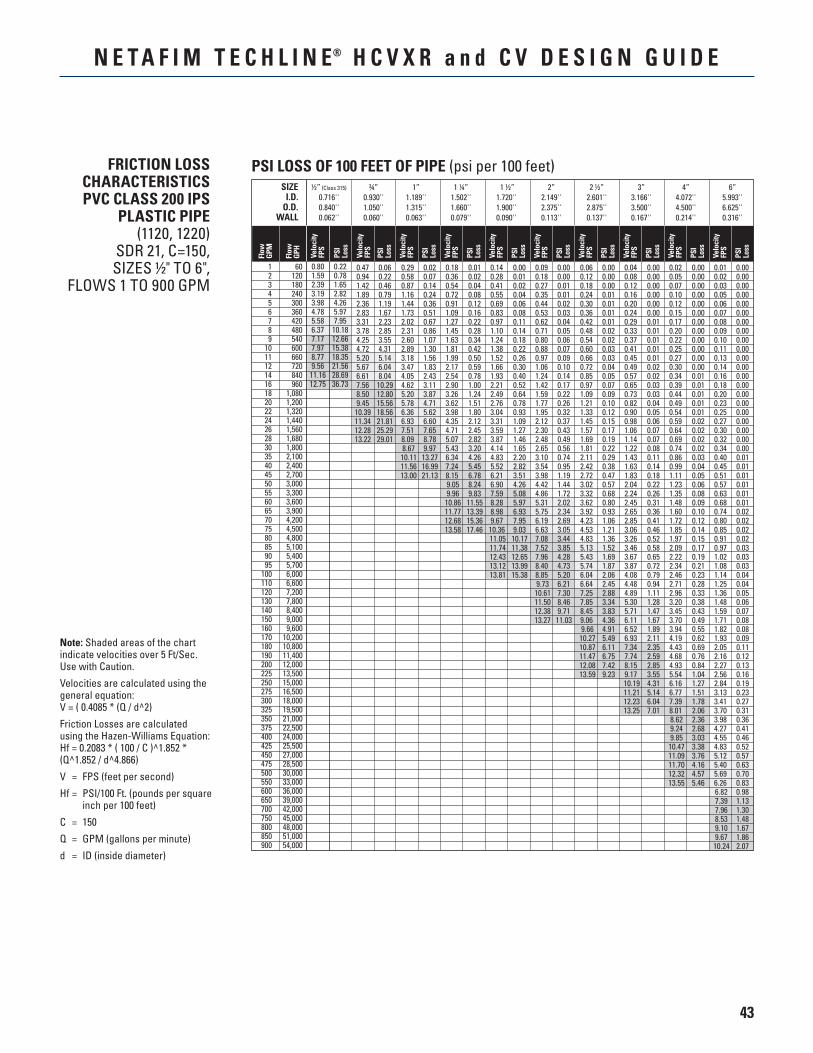
43
N E T A F I M T E C H L I N E® H C V X R a n d C V D E S I G N G U I D E
PSI LOSS OF 100 FEET OF PIPE (psi per 100 feet)
Flow
GPM
Flow
GPH
Velo
city
FPS
Velo
city
FPS
SIZE ¾” 1” 1 ¼” 1 ½” 2” 2 ½” 3” 4” 6” I.D. 0.930'' 1.189'' 1.502'' 1.720'' 2.149'' 2.601'' 3.166'' 4.072'' 5.993'' O.D. 1.050'' 1.315'' 1.660'' 1.900'' 2.375'' 2.875'' 3.500'' 4.500'' 6.625'' WALL 0.060'' 0.063'' 0.079'' 0.090'' 0.113'' 0.137'' 0.167'' 0.214'' 0.316''
PSI
Loss
PSI
Loss
Velo
city
FPS
PSI
Loss
Velo
city
FPS
PSI
Loss
Velo
city
FPS
PSI
Loss
Velo
city
FPS
PSI
Loss
Velo
city
FPS
PSI
Loss
Velo
city
FPS
PSI
Loss
Velo
city
FPS
PSI
Loss
Velo
city
FPS
PSI
Loss
1 60 2 120 3 180 4 240 5 300 6 360 7 420 8 480 9 540 10 600 11 660 12 720 14 840 16 960 18 1,080 20 1,200 22 1,320 24 1,440 26 1,560 28 1,680 30 1,800 35 2,100 40 2,400 45 2,700 50 3,000 55 3,300 60 3,600 65 3,900 70 4,200 75 4,500 80 4,800 85 5,100 90 5,400 95 5,700 100 6,000 110 6,600 120 7,200 130 7,800 140 8,400 150 9,000 160 9,600 170 10,200 180 10,800 190 11,400 200 12,000 225 13,500 250 15,000 275 16,500 300 18,000 325 19,500 350 21,000 375 22,500 400 24,000 425 25,500 450 27,000 475 28,500 500 30,000 550 33,000 600 36,000 650 39,000 700 42,000 750 45,000 800 48,000 850 51,000 900 54,000
0.80 0.22 1.59 0.78 2.39 1.65 3.19 2.82 3.98 4.26 4.78 5.97 5.58 7.95 6.37 10.18 7.17 12.66 7.97 15.38 8.77 18.35 9.56 21.56 11.16 28.69 12.75 36.73
0.47 0.06 0.29 0.02 0.18 0.01 0.14 0.00 0.09 0.00 0.06 0.00 0.04 0.00 0.02 0.00 0.01 0.00 0.94 0.22 0.58 0.07 0.36 0.02 0.28 0.01 0.18 0.00 0.12 0.00 0.08 0.00 0.05 0.00 0.02 0.00 1.42 0.46 0.87 0.14 0.54 0.04 0.41 0.02 0.27 0.01 0.18 0.00 0.12 0.00 0.07 0.00 0.03 0.00 1.89 0.79 1.16 0.24 0.72 0.08 0.55 0.04 0.35 0.01 0.24 0.01 0.16 0.00 0.10 0.00 0.05 0.00 2.36 1.19 1.44 0.36 0.91 0.12 0.69 0.06 0.44 0.02 0.30 0.01 0.20 0.00 0.12 0.00 0.06 0.00 2.83 1.67 1.73 0.51 1.09 0.16 0.83 0.08 0.53 0.03 0.36 0.01 0.24 0.00 0.15 0.00 0.07 0.00 3.31 2.23 2.02 0.67 1.27 0.22 0.97 0.11 0.62 0.04 0.42 0.01 0.29 0.01 0.17 0.00 0.08 0.00 3.78 2.85 2.31 0.86 1.45 0.28 1.10 0.14 0.71 0.05 0.48 0.02 0.33 0.01 0.20 0.00 0.09 0.00 4.25 3.55 2.60 1.07 1.63 0.34 1.24 0.18 0.80 0.06 0.54 0.02 0.37 0.01 0.22 0.00 0.10 0.00 4.72 4.31 2.89 1.30 1.81 0.42 1.38 0.22 0.88 0.07 0.60 0.03 0.41 0.01 0.25 0.00 0.11 0.00 5.20 5.14 3.18 1.56 1.99 0.50 1.52 0.26 0.97 0.09 0.66 0.03 0.45 0.01 0.27 0.00 0.13 0.00 5.67 6.04 3.47 1.83 2.17 0.59 1.66 0.30 1.06 0.10 0.72 0.04 0.49 0.02 0.30 0.00 0.14 0.00 6.61 8.04 4.05 2.43 2.54 0.78 1.93 0.40 1.24 0.14 0.85 0.05 0.57 0.02 0.34 0.01 0.16 0.00 7.56 10.29 4.62 3.11 2.90 1.00 2.21 0.52 1.42 0.17 0.97 0.07 0.65 0.03 0.39 0.01 0.18 0.00 8.50 12.80 5.20 3.87 3.26 1.24 2.49 0.64 1.59 0.22 1.09 0.09 0.73 0.03 0.44 0.01 0.20 0.00 9.45 15.56 5.78 4.71 3.62 1.51 2.76 0.78 1.77 0.26 1.21 0.10 0.82 0.04 0.49 0.01 0.23 0.00 10.39 18.56 6.36 5.62 3.98 1.80 3.04 0.93 1.95 0.32 1.33 0.12 0.90 0.05 0.54 0.01 0.25 0.00 11.34 21.81 6.93 6.60 4.35 2.12 3.31 1.09 2.12 0.37 1.45 0.15 0.98 0.06 0.59 0.02 0.27 0.00 12.28 25.29 7.51 7.65 4.71 2.45 3.59 1.27 2.30 0.43 1.57 0.17 1.06 0.07 0.64 0.02 0.30 0.00 13.22 29.01 8.09 8.78 5.07 2.82 3.87 1.46 2.48 0.49 1.69 0.19 1.14 0.07 0.69 0.02 0.32 0.00 8.67 9.97 5.43 3.20 4.14 1.65 2.65 0.56 1.81 0.22 1.22 0.08 0.74 0.02 0.34 0.00 10.11 13.27 6.34 4.26 4.83 2.20 3.10 0.74 2.11 0.29 1.43 0.11 0.86 0.03 0.40 0.01 11.56 16.99 7.24 5.45 5.52 2.82 3.54 0.95 2.42 0.38 1.63 0.14 0.99 0.04 0.45 0.01 13.00 21.13 8.15 6.78 6.21 3.51 3.98 1.19 2.72 0.47 1.83 0.18 1.11 0.05 0.51 0.01 9.05 8.24 6.90 4.26 4.42 1.44 3.02 0.57 2.04 0.22 1.23 0.06 0.57 0.01 9.96 9.83 7.59 5.08 4.86 1.72 3.32 0.68 2.24 0.26 1.35 0.08 0.63 0.01 10.86 11.55 8.28 5.97 5.31 2.02 3.62 0.80 2.45 0.31 1.48 0.09 0.68 0.01 11.77 13.39 8.98 6.93 5.75 2.34 3.92 0.93 2.65 0.36 1.60 0.10 0.74 0.02 12.68 15.36 9.67 7.95 6.19 2.69 4.23 1.06 2.85 0.41 1.72 0.12 0.80 0.02 13.58 17.46 10.36 9.03 6.63 3.05 4.53 1.21 3.06 0.46 1.85 0.14 0.85 0.02 11.05 10.17 7.08 3.44 4.83 1.36 3.26 0.52 1.97 0.15 0.91 0.02 11.74 11.38 7.52 3.85 5.13 1.52 3.46 0.58 2.09 0.17 0.97 0.03 12.43 12.65 7.96 4.28 5.43 1.69 3.67 0.65 2.22 0.19 1.02 0.03 13.12 13.99 8.40 4.73 5.74 1.87 3.87 0.72 2.34 0.21 1.08 0.03 13.81 15.38 8.85 5.20 6.04 2.06 4.08 0.79 2.46 0.23 1.14 0.04 9.73 6.21 6.64 2.45 4.48 0.94 2.71 0.28 1.25 0.04 10.61 7.30 7.25 2.88 4.89 1.11 2.96 0.33 1.36 0.05 11.50 8.46 7.85 3.34 5.30 1.28 3.20 0.38 1.48 0.06 12.38 9.71 8.45 3.83 5.71 1.47 3.45 0.43 1.59 0.07 13.27 11.03 9.06 4.36 6.11 1.67 3.70 0.49 1.71 0.08 9.66 4.91 6.52 1.89 3.94 0.55 1.82 0.08 10.27 5.49 6.93 2.11 4.19 0.62 1.93 0.09 10.87 6.11 7.34 2.35 4.43 0.69 2.05 0.11 11.47 6.75 7.74 2.59 4.68 0.76 2.16 0.12 12.08 7.42 8.15 2.85 4.93 0.84 2.27 0.13 13.59 9.23 9.17 3.55 5.54 1.04 2.56 0.16 10.19 4.31 6.16 1.27 2.84 0.19 11.21 5.14 6.77 1.51 3.13 0.23 12.23 6.04 7.39 1.78 3.41 0.27 13.25 7.01 8.01 2.06 3.70 0.31 8.62 2.36 3.98 0.36 9.24 2.68 4.27 0.41 9.85 3.03 4.55 0.46 10.47 3.38 4.83 0.52 11.09 3.76 5.12 0.57 11.70 4.16 5.40 0.63 12.32 4.57 5.69 0.70 13.55 5.46 6.26 0.83 6.82 0.98 7.39 1.13 7.96 1.30 8.53 1.48 9.10 1.67 9.67 1.86 10.24 2.07
½” (Class 315)
0.716''0.840''0.062''
FRICTION LOSS CHARACTERISTICS PVC CLASS 200 IPS
PLASTIC PIPE(1120, 1220)
SDR 21, C=150,SIZES ½" TO 6",
FLOWS 1 TO 900 GPM
Note: Shaded areas of the chart indicate velocities over 5 Ft/Sec. Use with Caution.
Velocities are calculated using the general equation: V = ( 0.4085 * (Q / d^2)
Friction Losses are calculated using the Hazen-Williams Equation: Hf = 0.2083 * ( 100 / C )^1.852 * (Q^1.852 / d^4.866)
V = FPS (feet per second)
Hf = PSI/100 Ft. (pounds per square inch per 100 feet)
C = 150
Q = GPM (gallons per minute)
d = ID (inside diameter)


LTLCVDG 11/16
NETAFIM USA5470 E. HOME AVE.FRESNO, CA 93727CS 888 638 2346www.netafimusa.com
TECHLINE HCVXRAND CV DESIGN GUIDEDRIPLINE FOR SUBSURFACE AND ON-SURFACE


