16
FDKS/FDXS-C Concealed Ceiling, Inverter Controlled Unit technical data Split Sky Air air conditioning systems
FDKS/FDXS-C
Concealed Ceiling, Inverter Controlled Unit
technical data
SplitSky Air
air co
nd
ition
ing
system
s
Split - Sky Air
EE
DE0
5-1
/3 •
05/2
005
Prepar
ed in
Belg
ium
by
Goeki
nt
Gra
phic
s
Zandvoordestraat 300
B - 8400 Ostend Belgium
Specifications are subject to change without prior notice.
ISO14001 assures an effective environmental management system in order to help protecthuman health and the environment from the potentialimpact of our activities, products and services and toassist in maintaining and improving the quality ofthe environment
Daikin Europe N.V. is approved by LRQA for its Quality Management System in accordance with the ISO9001 standard. ISO9001 pertains to quality assurance regarding design, development, manufacturing as well as to services related to the product.
Daikin units comply with the European regulations that guarantee the safety of the product.
Daikin Europe N.V. participates in the Eurovent Certification Programme for Air Conditioners (AC), Liquid Chilling Packages (LCP) and Fan Coil Units (FC); the certified data of certified models are listed in the Eurovent Directory.
www.daikineurope.com

• Split Sky Air • Indoor Units 1
• Indoor Units • R410A • FDK/XS-CVMB
TABLE OF CONTENTSFDK/XS-CVMB
1 Features. . . . . . . . . . . . . . . . . . . . . . . . . . . . . . . . . . . . . . . . . . . . . . . . . . . . . . . . . . . . . . . . . . . . . . 2
2 Specifications. . . . . . . . . . . . . . . . . . . . . . . . . . . . . . . . . . . . . . . . . . . . . . . . . . . . . . . . . . . . . . . . 3
FDKS-DNominal capacity and power input . . . . . . . . . . . . . . . . . . . . . . . . . . . . . . . . . . . . . . . . . . . 3
Technical Specifications . . . . . . . . . . . . . . . . . . . . . . . . . . . . . . . . . . . . . . . . . . . . . . . . . . . . . . 3
Electrical Specifications . . . . . . . . . . . . . . . . . . . . . . . . . . . . . . . . . . . . . . . . . . . . . . . . . . . . . . . 4FDXS-DNominal capacity and power input . . . . . . . . . . . . . . . . . . . . . . . . . . . . . . . . . . . . . . . . . . . 5
Technical Specifications . . . . . . . . . . . . . . . . . . . . . . . . . . . . . . . . . . . . . . . . . . . . . . . . . . . . . . 5
Electrical Specifications . . . . . . . . . . . . . . . . . . . . . . . . . . . . . . . . . . . . . . . . . . . . . . . . . . . . . . . 7
3 Dimensional drawing & centre of gravity. . . . . . . . . . . . . . . . . . . . . . . . . . . . . . . . . 8
Dimensional drawing . . . . . . . . . . . . . . . . . . . . . . . . . . . . . . . . . . . . . . . . . . . . . . . . . . . . . . . . . 8
Centre of gravity . . . . . . . . . . . . . . . . . . . . . . . . . . . . . . . . . . . . . . . . . . . . . . . . . . . . . . . . . . . . . 9
4 Piping diagram . . . . . . . . . . . . . . . . . . . . . . . . . . . . . . . . . . . . . . . . . . . . . . . . . . . . . . . . . . . . . 10
5 Wiring diagram . . . . . . . . . . . . . . . . . . . . . . . . . . . . . . . . . . . . . . . . . . . . . . . . . . . . . . . . . . . . 11
6 Sound data . . . . . . . . . . . . . . . . . . . . . . . . . . . . . . . . . . . . . . . . . . . . . . . . . . . . . . . . . . . . . . . . . 12
Sound pressure spectrum . . . . . . . . . . . . . . . . . . . . . . . . . . . . . . . . . . . . . . . . . . . . . . . . . . . . 12
7 Fan characteristics . . . . . . . . . . . . . . . . . . . . . . . . . . . . . . . . . . . . . . . . . . . . . . . . . . . . . . . . . 14
• Indoor Units • R410A • FDK/XS-CVMB
• Split Sky Air • Indoor Units2
121
Indoor Split FDK/XS- R410a 1 Features
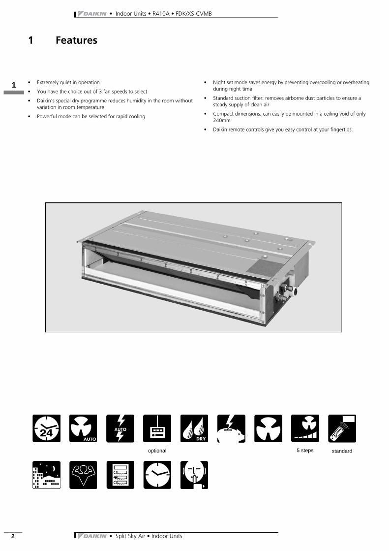
• Extremely quiet in operation
• You have the choice out of 3 fan speeds to select
• Daikin’s special dry programme reduces humidity in the room without variation in room temperature
• Powerful mode can be selected for rapid cooling
• Night set mode saves energy by preventing overcooling or overheating during night time
• Standard suction filter: removes airborne dust particles to ensure a steady supply of clean air
• Compact dimensions, can easily be mounted in a ceiling void of only 240mm
• Daikin remote controls give you easy control at your fingertips.
optional 5 steps standard
122
• Split Sky Air • Indoor Units 3
• Indoor Units • R410A • FDK/XS-CVMB
2 Specifications
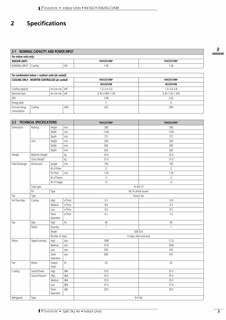
2-1 NOMINAL CAPACITY AND POWER INPUTFor indoor units only:INDOOR UNITS FDKS25CVMB* FDKS35CVMB*
NOMINAL INPUT Cooling kW 1.00 1.00
For combination indoor + outdoor units (air cooled):COOLING ONLY - INVERTER CONTROLLED (air cooled) FDKS25CVMB* FDKS35CVMB*
RKS25DVMB RKS35DVMB
Cooling capacity min~nom~max kW 1.3~2.4~3.0 1.4~3.4~3.8
Nominal input min~nom~max kW 0.30~0.845~1.06 0.30~1.30~1.455
EER 2.48 2.62
Energy label C D
Annual energy consumption
Cooling kWh 423 650
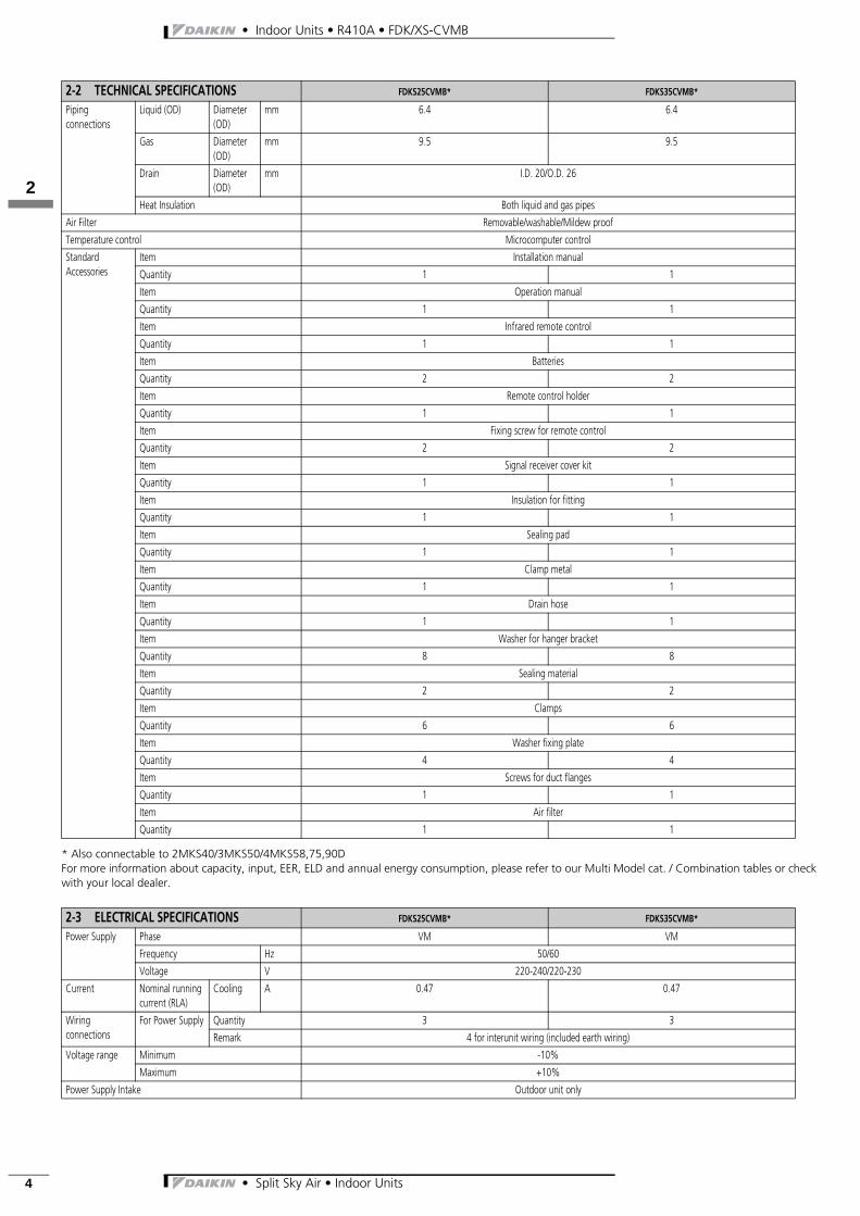
2-2 TECHNICAL SPECIFICATIONS FDKS25CVMB* FDKS35CVMB*
Dimensions Packing Height mm 266 266
Width mm 1106 1106
Depth mm 751 751
Unit Height mm 200 200
Width mm 900 900
Depth mm 620 620
Weight Machine Weight kg 25.0 25.0
Gross Weight kg 31.0 31.0
Heat Exchanger Dimensions Length mm 700 700
Nr of Rows 2 2
Fin Pitch mm 1.50 1.50
Nr of Passes 2 2
Nr of Stages 12 12
Tube type Hi-XSS (7)
Fin Type ML fin (Multi louver)
Fan Type Sirocco fan
Air Flow Rate Cooling High m3/min 9.5 10.0
Medium m3/min 8.8 9.3
Low m3/min 8.0 8.5
Silent Operation
m3/min 6.7 7.0
Fan Max High Pa 40 40
Motor Quantity 1 1
Model 62B-23A
Number of steps 5 steps, silent and auto
Motor Speed (cooling) High rpm 1090 1110
Medium rpm 1010 1040
Low rpm 930 970
Silent Operation
rpm 800 810
Fan Motor Output (high)
W 62 62
Cooling Sound Power High dBA 53.0 53.0
Sound Pressure High dBA 35.0 35.0
Medium dBA 33.0 33.0
Low dBA 31.0 31.0
Silent Operation
dBA 29.0 29.0
Refrigerant Type R-410A
• Indoor Units • R410A • FDK/XS-CVMB
• Split Sky Air • Indoor Units4
122
* Also connectable to 2MKS40/3MKS50/4MKS58,75,90DFor more information about capacity, input, EER, ELD and annual energy consumption, please refer to our Multi Model cat. / Combination tables or check with your local dealer.
Piping connections
Liquid (OD) Diameter (OD)
mm 6.4 6.4
Gas Diameter (OD)
mm 9.5 9.5
Drain Diameter (OD)
mm I.D. 20/O.D. 26
Heat Insulation Both liquid and gas pipes
Air Filter Removable/washable/Mildew proof
Temperature control Microcomputer control
Standard Accessories
Item Installation manual
Quantity 1 1
Item Operation manual
Quantity 1 1
Item Infrared remote control
Quantity 1 1
Item Batteries
Quantity 2 2
Item Remote control holder
Quantity 1 1
Item Fixing screw for remote control
Quantity 2 2
Item Signal receiver cover kit
Quantity 1 1
Item Insulation for fitting
Quantity 1 1
Item Sealing pad
Quantity 1 1
Item Clamp metal
Quantity 1 1
Item Drain hose
Quantity 1 1
Item Washer for hanger bracket
Quantity 8 8
Item Sealing material
Quantity 2 2
Item Clamps
Quantity 6 6
Item Washer fixing plate
Quantity 4 4
Item Screws for duct flanges
Quantity 1 1
Item Air filter
Quantity 1 1
2-3 ELECTRICAL SPECIFICATIONS FDKS25CVMB* FDKS35CVMB*
Power Supply Phase VM VM
Frequency Hz 50/60
Voltage V 220-240/220-230
Current Nominal running current (RLA)
Cooling A 0.47 0.47
Wiring connections
For Power Supply Quantity 3 3
Remark 4 for interunit wiring (included earth wiring)
Voltage range Minimum -10%
Maximum +10%
Power Supply Intake Outdoor unit only
2-2 TECHNICAL SPECIFICATIONS FDKS25CVMB* FDKS35CVMB*
122
• Split Sky Air • Indoor Units 5
• Indoor Units • R410A • FDK/XS-CVMB
2 Specifications
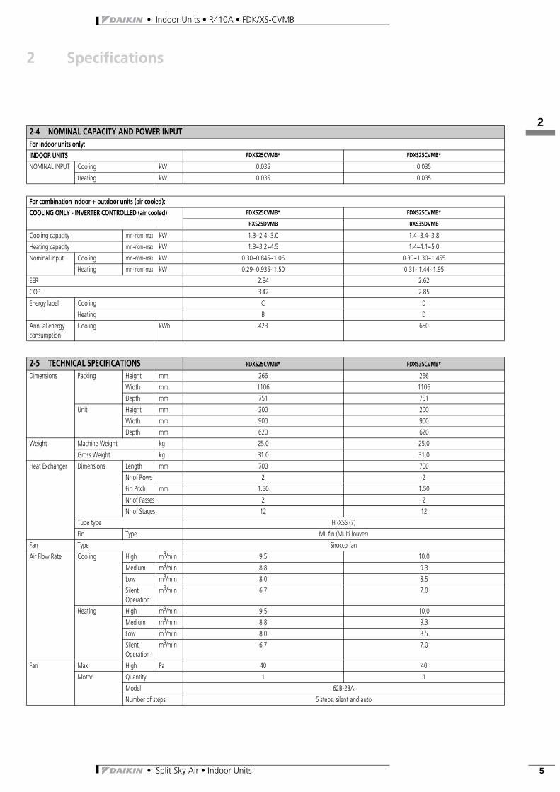
2-4 NOMINAL CAPACITY AND POWER INPUTFor indoor units only:INDOOR UNITS FDXS25CVMB* FDXS25CVMB*
NOMINAL INPUT Cooling kW 0.035 0.035
Heating kW 0.035 0.035
For combination indoor + outdoor units (air cooled):COOLING ONLY - INVERTER CONTROLLED (air cooled) FDXS25CVMB* FDXS25CVMB*
RXS25DVMB RXS35DVMB
Cooling capacity min~nom~max kW 1.3~2.4~3.0 1.4~3.4~3.8
Heating capacity min~nom~max kW 1.3~3.2~4.5 1.4~4.1~5.0
Nominal input Cooling min~nom~max kW 0.30~0.845~1.06 0.30~1.30~1.455
Heating min~nom~max kW 0.29~0.935~1.50 0.31~1.44~1.95
EER 2.84 2.62
COP 3.42 2.85
Energy label Cooling C D
Heating B D
Annual energy consumption
Cooling kWh 423 650
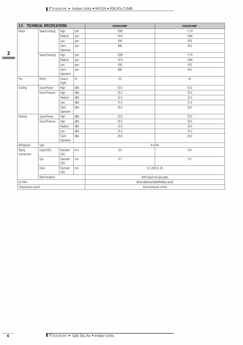
2-5 TECHNICAL SPECIFICATIONS FDXS25CVMB* FDXS35CVMB*
Dimensions Packing Height mm 266 266
Width mm 1106 1106
Depth mm 751 751
Unit Height mm 200 200
Width mm 900 900
Depth mm 620 620
Weight Machine Weight kg 25.0 25.0
Gross Weight kg 31.0 31.0
Heat Exchanger Dimensions Length mm 700 700
Nr of Rows 2 2
Fin Pitch mm 1.50 1.50
Nr of Passes 2 2
Nr of Stages 12 12
Tube type Hi-XSS (7)
Fin Type ML fin (Multi louver)
Fan Type Sirocco fan
Air Flow Rate Cooling High m3/min 9.5 10.0
Medium m3/min 8.8 9.3
Low m3/min 8.0 8.5
Silent Operation
m3/min 6.7 7.0
Heating High m3/min 9.5 10.0
Medium m3/min 8.8 9.3
Low m3/min 8.0 8.5
Silent Operation
m3/min 6.7 7.0
Fan Max High Pa 40 40
Motor Quantity 1 1
Model 62B-23A
Number of steps 5 steps, silent and auto
• Indoor Units • R410A • FDK/XS-CVMB
• Split Sky Air • Indoor Units6
122
Motor Speed (cooling) High rpm 1090 1110
Medium rpm 1010 1040
Low rpm 930 970
Silent Operation
rpm 800 810
Speed (heating) High rpm 1090 1110
Medium rpm 1010 1040
Low rpm 930 970
Silent Operation
rpm 800 810
Fan Motor Output (high)
W 62 62
Cooling Sound Power High dBA 53.0 53.0
Sound Pressure High dBA 35.0 35.0
Medium dBA 33.0 33.0
Low dBA 31.0 31.0
Silent Operation
dBA 29.0 29.0
Heating Sound Power High dBA 53.0 53.0
Sound Pressure High dBA 35.0 35.0
Medium dBA 33.0 33.0
Low dBA 31.0 31.0
Silent Operation
dBA 29.0 29.0
Refrigerant Type R-410A
Piping connections
Liquid (OD) Diameter (OD)
mm 6.4 6.4
Gas Diameter (OD)
mm 9.5 9.5
Drain Diameter (OD)
mm I.D. 20/O.D. 26
Heat Insulation Both liquid and gas pipes
Air Filter Removable/washable/Mildew proof
Temperature control Microcomputer control
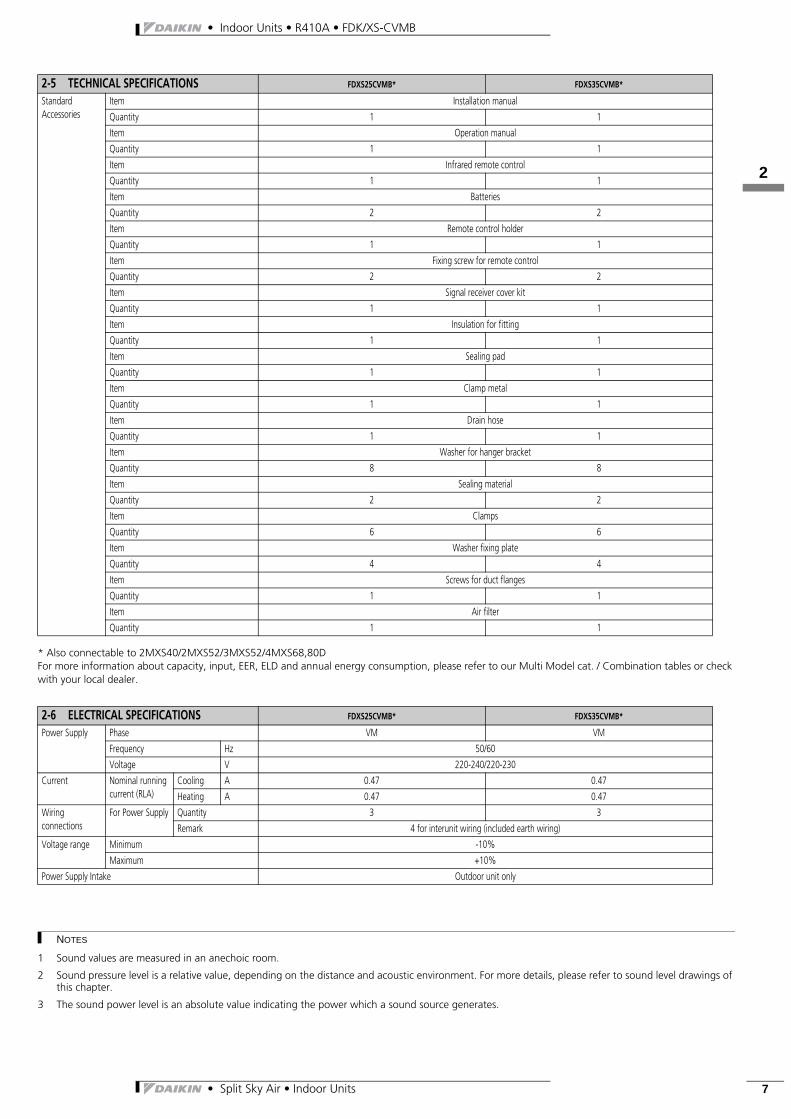
2-5 TECHNICAL SPECIFICATIONS FDXS25CVMB* FDXS35CVMB*
122
• Split Sky Air • Indoor Units 7
• Indoor Units • R410A • FDK/XS-CVMB
* Also connectable to 2MXS40/2MXS52/3MXS52/4MXS68,80DFor more information about capacity, input, EER, ELD and annual energy consumption, please refer to our Multi Model cat. / Combination tables or check with your local dealer.
Standard Accessories
Item Installation manual
Quantity 1 1
Item Operation manual
Quantity 1 1
Item Infrared remote control
Quantity 1 1
Item Batteries
Quantity 2 2
Item Remote control holder
Quantity 1 1
Item Fixing screw for remote control
Quantity 2 2
Item Signal receiver cover kit
Quantity 1 1
Item Insulation for fitting
Quantity 1 1
Item Sealing pad
Quantity 1 1
Item Clamp metal
Quantity 1 1
Item Drain hose
Quantity 1 1
Item Washer for hanger bracket
Quantity 8 8
Item Sealing material
Quantity 2 2
Item Clamps
Quantity 6 6
Item Washer fixing plate
Quantity 4 4
Item Screws for duct flanges
Quantity 1 1
Item Air filter
Quantity 1 1
2-6 ELECTRICAL SPECIFICATIONS FDXS25CVMB* FDXS35CVMB*
Power Supply Phase VM VM
Frequency Hz 50/60
Voltage V 220-240/220-230
Current Nominal running current (RLA)
Cooling A 0.47 0.47
Heating A 0.47 0.47
Wiring connections
For Power Supply Quantity 3 3
Remark 4 for interunit wiring (included earth wiring)
Voltage range Minimum -10%
Maximum +10%
Power Supply Intake Outdoor unit only
2-5 TECHNICAL SPECIFICATIONS FDXS25CVMB* FDXS35CVMB*
NOTES
1 Sound values are measured in an anechoic room.
2 Sound pressure level is a relative value, depending on the distance and acoustic environment. For more details, please refer to sound level drawings of this chapter.
3 The sound power level is an absolute value indicating the power which a sound source generates.

• Indoor Units • R410A • FDK/XS-CVMB
• Split Sky Air • Indoor Units8
123
3 Dimensional drawing & centre of gravity
3 - 1 Dimensional drawing
FDK/XS25,35CVMB
3D045486B
300 or more(service space)
(sus
pens
ion
bolt
pitc
h)
(suspension bolt pitch)
(all around)22-ø4.7 hole
Suspension bolt4-M8~M10
18-M4 holes(all around)
20-M5 holes(all around)
< In case of bottom-suction >
< Service space >
Ceiling
240
or m
ore
20 o
r mor
e
20 o
r mor
e
400 or more(in case of
bottom suction)
Allow view AInspection door(ceiling opening)
20-M5 holes(all around)
Infrared receiver unit
Home leave lamp
Indoor unit on/off switch
Timer lamp
Operation lamp Room temp. sensor
Signal receiver cord (length: 1900 mm)
Wireless remote controllerCDXS--CVMB: (ARC433A7)CDKS--CVMB: (ARC433A8)
FDXS--CVMB: (ARC433A7)FDKS--CVMB: (ARC433A8)
Signal transmitter
A
LEGEND1 Liquid pipe connection: ø 6.4 flare
(connection)2 Gas pipe connection: see note 4.3 Socket for drain: VP20 (O.D. ø26, I.D. ø20)4 Drain hose (accessory): I.D. ø25 (outlet)5 Control box6 Infrared receiver unit connection7 Power supply connection8 Suspension bracket9 Air filter (accessory)
NOTES1 In case of back-suction, mount chamber cover to bottom side of the unit. In
case of bottom-suction, mount chamber cover to back side of the unit.2 Location of unit’s name plate: control box cover.3 Mount the air filter at the suction side.
(Select its colorimethod (gravity method) 50 % or more)It can not be equipped with air filter (accessory) when connecting duct to suction side.
4 Pipe specification
FDX(K)S25
ø 9.5 (flare connection)CDX(K)S25FDX(K)S35CDX(K)S35CDX(K)S50 ø 12.7 (flare connection)
123
• Split Sky Air • Indoor Units 9
• Indoor Units • R410A • FDK/XS-CVMB
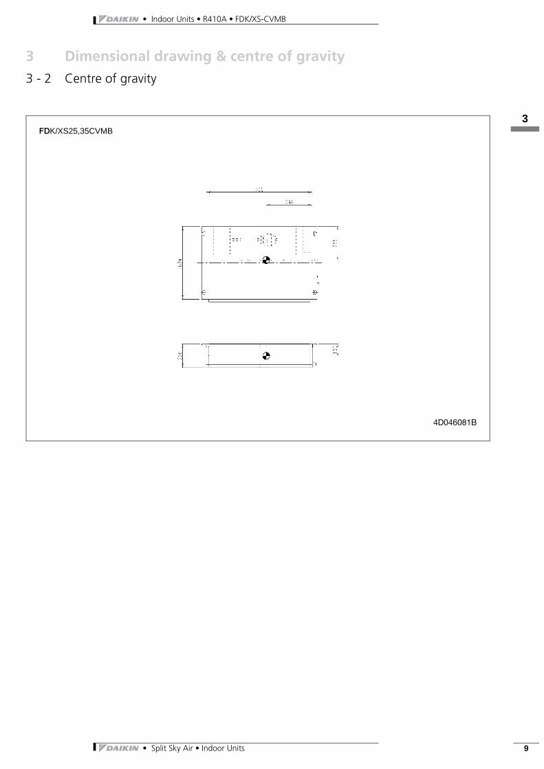
3 Dimensional drawing & centre of gravity
3 - 2 Centre of gravity
FDK/XS25,35CVMB
4D046081B
• Indoor Units • R410A • FDK/XS-CVMB
• Split Sky Air • Indoor Units10
124
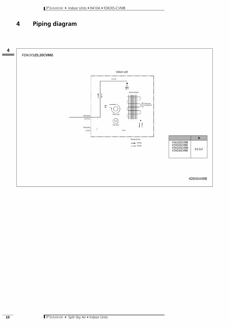
4 Piping diagram
FDK/XS25,35CVMB
4D045449B
Thermistoron heat exch.
Sirocco fanField piping
(6.4 CuT)
Field piping
(A CuT)
Fan motor
Refrigerant flow
Cooling
Heating
A CuT
Heat exchanger
Indoor unit
6.4 CuT
A
FDKS25CVMBFDXS25CVMBFDKS35CVMBFDXS35CVMB 9.5 CuT
125
• Split Sky Air • Indoor Units 11
• Indoor Units • R410A • FDK/XS-CVMB
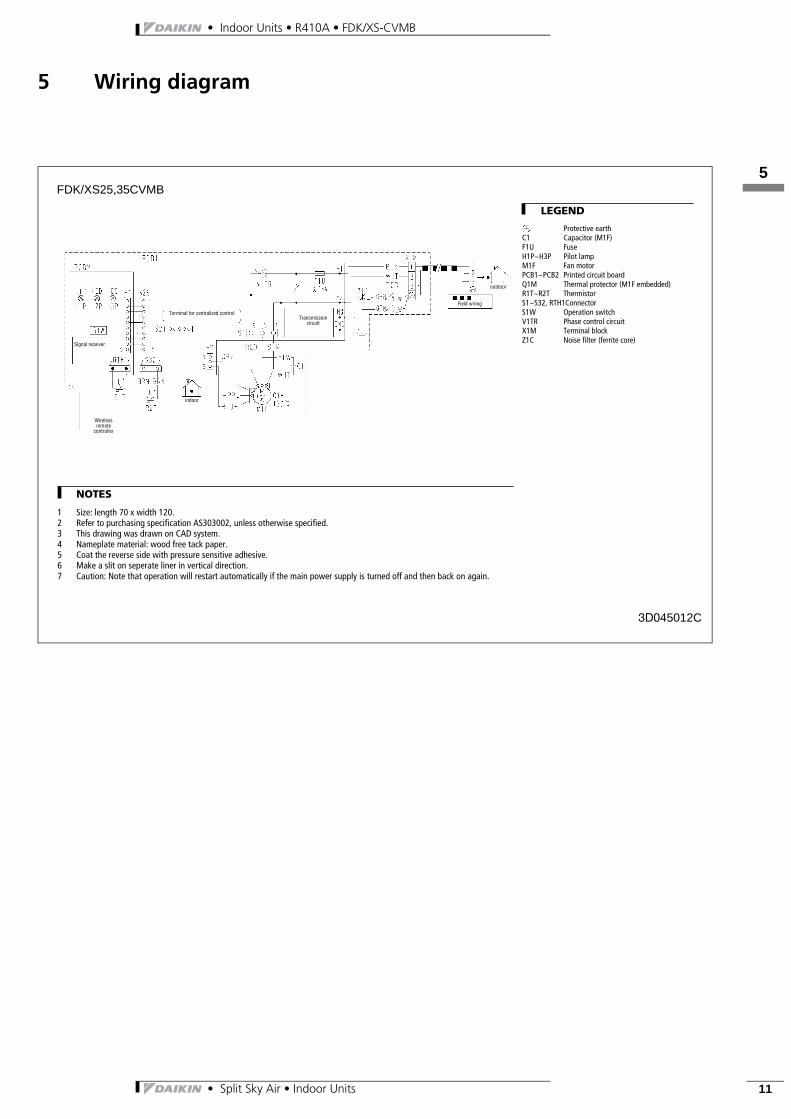
5 Wiring diagram
FDK/XS25,35CVMB
3D045012C
Wireless remote
controller
indoor
outdoor
Transmission circuit
Field wiring
Signal receiver
Terminal for centralized control
LEGEND
Protective earthC1 Capacitor (M1F)F1U FuseH1P~H3P Pilot lampM1F Fan motorPCB1~PCB2 Printed circuit boardQ1M Thermal protector (M1F embedded)R1T~R2T ThermistorS1~S32, RTH1ConnectorS1W Operation switchV1TR Phase control circuitX1M Terminal blockZ1C Noise filter (ferrite core)
NOTES
1 Size: length 70 x width 120.2 Refer to purchasing specification AS303002, unless otherwise specified.3 This drawing was drawn on CAD system.4 Nameplate material: wood free tack paper.5 Coat the reverse side with pressure sensitive adhesive.6 Make a slit on seperate liner in vertical direction.7 Caution: Note that operation will restart automatically if the main power supply is turned off and then back on again.
• Indoor Units • R410A • FDK/XS-CVMB
• Split Sky Air • Indoor Units12
126
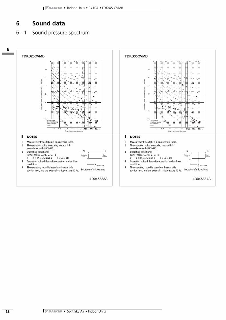
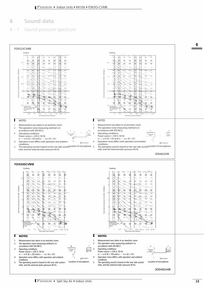
6 Sound data
6 - 1 Sound pressure spectrum
FDKS25CVMB
4D046333A
Approximate threshold hearing for continuous noise
Octave band center frequency
Oct
ave
band
sou
nd p
ress
ure
leve
l (0d
B =
0.0
002μ
bar)
NOTES
1 Measurement was taken in an anechoic room.2 The operation noise measuring method is in
accordance with JISC9612.3 Operating conditions:
Power source = 230 V, 50 Hzo------o H (A = 35) and o- - - -o L (A = 31)
4 Operation noise differs with operation and ambient conditions.
5 The operating sound is based on the rear side suction inlet, and the external static pressure 40 Pa. Location of microphone
Discharge duct
Duct suction
Microphone
126
• Split Sky Air • Indoor Units 13
• Indoor Units • R410A • FDK/XS-CVMB
6 Sound data
6 - 1 Sound pressure spectrum
FDXS35CVMB
3D046244B
Approximate threshold hearing for continuous noise
Approximate threshold hearing for continuous noise
Octave band center frequencyOctave band center frequency
Oct
ave
band
sou
nd p
ress
ure
leve
l (0d
B =
0.00
02μb
ar)
Oct
ave
band
sou
nd p
ress
ure
leve
l (0d
B =
0.0
002μ
bar)
NOTES
1 Measurement was taken in an anechoic room.2 The operation noise measuring method is in
accordance with JISC9612.3 Operating conditions:
Power source = 230 V, 50 Hzo------o H (A = 35) and o- - - -o L (A = 31)
4 Operation noise differs with operation and ambient conditions.
5 The operating sound is based on the rear side suction inlet, and the external static pressure 40 Pa.
Location of microphone
Cooling Heating
Discharge duct
Duct suction
Microphone
Discharge duct
Duct suction
Microphone
• Indoor Units • R410A • FDK/XS-CVMB
• Split Sky Air • Indoor Units14
127
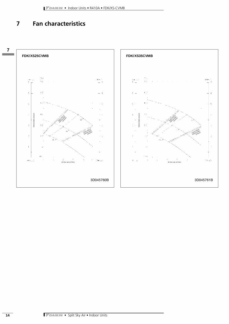
7 Fan characteristics
FDK/XS25CVMB
3D045760B
Exte
rnal
sta
tic p
ress
ure
Air flow rate (m³/min)
Lower limit of
external static
pressure
Upper l
imit o
f
exter
nal s
tatic
press
ure
FDK/XS35CVMB
3D045761B
Exte
rnal
sta
tic p
ress
ure
Air flow rate (m³/min)
Lower limit of
external static
pressure
Upper limit of
extern
alstat
ic
pressure


