1 5515 (supersedes 5496)---1207---L9 348 HYLAB 5 Link-Belt Cranes Technical Dat a Specifications & Capacities Crawler Crane 300 Ton (272.16 metric ton) CAUTION: This material is supplied for reference use only. Operator must refer to in---cab Crane Rating Manual and Operator’s Manual to determine allowable crane lifting capacities and assembly and operating procedures.
Transcript
15515 (supersedes 5496)---1207---L9
348 HYLAB 5Link-Belt Cranes
Technical DataSpecifications & Capacities
Crawler Crane300 Ton (272.16 metric ton)
CAUTION: Thismaterial is supplied for referenceuseonly. Operator must refer to in---cab Crane RatingManual and Operator’s Manual to determineallowable crane lifting capacities and assembly andoperating procedures.
Fuel TankEquipped with fuel sight level gauges,flame arrester, and self ---closing cap withlocking eye for padlock.
Hydraulic System
Hydraulic PumpsThe pump arrangement is designed toprovide hydraulically powered functionsallowing positive, precise control with in-dependent or simultaneous operation ofall crane functions.S Two variable displacement pumpsoperating at 4,550 psi (320kg/cm2) and110 gal/min (416L/min) powers the loadhoist drums, boom hoist drum, optionalthird drum, optional fourth drum, andtravel.
S One variable displacement pumpoperating at 3,560 psi (250kg/cm2) and61.0 gal/min (231L/min) powers theswing motor.
S One fixed displacement gear type pumpoperating at 3,270 psi (230kg/cm2) and16.4 gal/min (62L/min) powers theself---assembly cylinder, counterweightlifting, lower jacks, and hydraulicbackstop and sideframe pin cylinders.
S One fixed displacement gear type pumpoperating at 1,140 psi (80kg/cm2) and11.1 gal/min (42.2L/min) powers theremote control valves, counterweight pinand boom foot pin cylinders.
S One fixed displacement gear typepump operating at 1,990 psi(140kg/cm2) and 8.5 gal/min(32.1L/min) powers the fan for the oilcooler, cab tilt cylinders, andcounterweight lifting cylinders at highspeed.
S One fixed displacement gear typepump operating at 35.6 psi (2.5kg/cm2)and 3.0 gal/min (11.4L/min)powers thesplitter oil cooler.
S One fixed displacement gear typepump operating at 4,550 psi(320kg/cm2) and 8.7 gal/min(32.9L/min) powers the live mast flipcylinders.
Remote Oil CoolerOil cooler, located behind the operator’scab, has a hydraulically driven, thermo-statically controlled fan to control oil tem-perature.
Pump Control “Fine Inching” ModeSpecial pump setting, selectable from theoperator’s cab, that allows very slowmovements of load hoist drums, boomhoist drum, and travel for precision work.
Hydraulic Reservoir108 gal (409L), equipped with sight levelgauge. Diffusers built in for deaeriation.
FiltrationTenmicron, full flow, line filter in thecontrolcircuit. All oil is filteredprior toentering thereservoir.
Counterbalance ValvesAll hoist motors are equipped with coun-terbalance valves to provide positive loadlowering and prevent accidental loaddrop if the hydraulic pressure is suddenlylost.
Load Hoist Drums
Eachdrumcontainsapilot controlled,bi ---directional, axial piston motor and a plan-etary gear reduction unit to provide posi-tive control under all load conditions.S Power up/down with optional free--- falloperation modes
S Automatic brakemode (spring applied,hydraulically released, band typebrake)
S Drum pawl controlled manuallyS Electronic drum rotation indicatorsS Mounted on anti --- friction bearingsS 22.68 in (57.61cm) root diameterS 44.88 in (114.00cm) flange diameterS 27.13 in (68.91cm) widthThe free--- fall operationmode is designedto prevent load lowering even if the free---fall switch is accidentally activated.
The automatic brake mode meets allOSHA requirements for personnel han-dling.
Drum ClutchesHydraulic two shoe clutch design thatuses a 37 in (939mm) diameter x 5.5 in(140mm) wide shoe that expands inter-nally to provide load control.
2 5515 (supersedes 5496)---1207---L9
348 HYLAB 5 Link-Belt Cranes
Optional Front---MountedThird Hoist DrumS Mounts in the boom base sectionS Power up/down for luffer applicationsS 20.72 in (526.3mm) root diameterS 34.84 in (885mm) flange diameterS 11.54 in (293.1mm) width
Boom Hoist Drum
Contains a pilot controlled, bi---directional,axial piston motor and a planetary gear re-duction unit to provide positive control un-der all load conditions.S Spring applied, hydraulically released,disc type brake controlled automatically
S Electronic drum rotation indicatorsS Drum pawl controlled automaticallyS Mounted on anti --- friction bearingsS 20.98 in (5329cm) root diameter (right)S 20.47 in (51.99cm) root diameter (left)S 39.37 in (100.00cm) flange diameterS 11.26 in (28.60cm) width (right)S 11.26 in (28.60cm) width (left)
Boom Hoist System
Designed to lift off maximum boom ormaximum boom plus jib and maximumluffing attachment unassisted. Operatesup to a maximum boom angle of 83˚.Boom hoist limit system limits maximumboom angle operation.S Pin---on bail frameS 24---part reeving with 1 in (26mm) wirerope
S Bridle assemblyS 32 ft (9.75m) Live mastS Hydraulic tubular boom backstopsS Sheaves contain sealed anti --- frictionbearings
Swing System
Pilot controlled, bi ---directional, axial pis-ton motors and planetary gear reductionunits to provide positive control under allload conditions.S Spring applied, hydraulically released,360˚ multi ---plate brake
S Free swing mode when lever is in neu-tral position
S Four position positive house lockS Audio/Visual swing alarmS Maximum swing speed is 1.7 rpmS Swing damper
Counterweight
Consists of a 13---piecedesign that canbeeasily lowered to the ground using thehy-draulic counterweight removal system.S “A” upper counterweight consists ofone, 36,128 lb (16387kg)base slabandtwo, 17,086 lb (7 750kg) type “1” coun-terweights.
S “AB” upper counterweight consists ofall “A” counterweight plus four, 17,086lb (7 750kg) type “1” counterweightsand two, 16,755 lb (7 600kg) type “2”counterweights.
S “ABC” upper counterweight consists ofall “AB” counterweight plus four, 12,125 lb(5 500kg) type “3” counterweights.
Total combined counterweight, “ABC” is221,100 lb (100 289kg). “C” counter-weight is an optional item.
Operator’s Cab
Fully enclosed modular steel compart-ment is independently mounted andpadded to protect against vibration andnoise.S Cab tilts up to 20˚S All tinted/tempered safety glassS Sliding entry door and front windowS 19,000 BTU hot water heaterS 18,600 BTU air conditionerS Door and window locksS Circulating fanS Sun visorS Cloth seatS DefrosterS Windshield wipers and washerS Dry chemical fire extinguisher
S Electronic drum rotation indicators forfront and rear hoist drums
S Six way adjustable seatS Foot throttleS Fully adjustable single axis controlsS Swing lever with twist---grip throttle withvariable pump output control, swingbrake, and horn located on handle
S Bubble type levelS Ergonomic gauge layoutS Controls shut off leverS Right hand control stand is adjustableby electric motor for operator comfort.
Rated Capacity LimiterSystem
The rated capacity limiter system is a boomhoist load cell system. This system pro-vides the operator with useful geometricaldata, to include:S Main boom lengthS Main boom angleS Live mast angle indicatorS Live mast load indicatorS Jib lengthS Jib angleS Operating modeS Load radiusS Boom tip heightS Audible alarmS Pre---warning lightS Overload lightS Load on hookS Function kick---outs including over loadS Operator settable stops (rampedstops)S Anti --- two block indicatorS Boom hoist dead end load cell (nolineriders)
Machinery Cab
Hinged doors (five on right side, four onleft side) formachinery access. Equippedwith rooftop access ladder and skid resist-ant finish on roof.
Catwalks
Standardon right and left sides. Catwalksfold and pin for reduced transport width.
35515 (supersedes 5496)---1207---L9
348 HYLAB 5Link-Belt Cranes
Lower StructureCarbody
Lower FrameAll welded high strength steel [100,000psi (689.48MPa) yield] box constructionframe with precision machined surfacesfor turntable bearing and rotating joint.S 11 ft 2 in (3.2m) overall widthS 17 ft 9 in (5.41m) overall length
Side Frames
Side FramesAllwelded, precisionmachined. Carbodycross axles positioned by dowels andheld in place with adjustable wedgepacks.S 19 ft 2 in (5.84m) retracted gaugeS 22 ft 0 in (6.71m) extended gaugeS 30 ft 8 in (9.35m) overall lengthS 50 in (1.27m) wide track shoes ---standard
S 60 in (1.52m) wide track shoes ---optional
S Sealed (oil filled) idler and drive plane-taries
S Compact travel drivesS Hydraulic self ---adjusting track tensionsystem
Track RollersS Thirteen sealed (oil filled) track rollersper side frame
S Four sealed auxiliary (carrier roller)track rollers per side frame
TracksHeat treated, self ---cleaning, multiplehinged track shoes joined by one---piecefull floating pins; 60 shoes per side frame
Take Up IdlersCast steel, heat treated, self ---cleaning,mounted on aluminum/bronze bushings,lubricated through the idler shaft.S Track Tension Adjustment --- Idler ad-justed bymeans of automatic track ten-sion device. Hydraulic cylinder pro-vides proper track tension. Track ten-sion determined by stop bolt.
Travel and Steering
Travel and SteeringEach side frame contains a pilot con-trolled, bi ---directional, axial piston motorandaplanetary gear reductionunit topro-vide positive control under all load condi-tions.S Individual control provides smooth,precise maneuverability including fullcounter---rotation.
S Spring applied, hydraulically releaseddisc type brake controlled automatically
S Axial piston motor with reduction gear islocated at inner drive end of each sideframe. Each track is driven simulta-neously or individually for straight---line,gradual turn, or pivot turn.
S Maximum travel speed is 1 mph(1.61km/h).
S Designed to 30% gradeability
Jack System
System contains four hydraulic cylindersindividually mounted on swing---outbeams.S Individual jack cylinders are operatedby remote control, or can be operatedby carbody---mounted controls
S Minimum height of carbody when rest-ing on pontoons is 17.4 in (44.20cm).
S Maximum height of carbody when rest-ing on pontoons is 44.0 in (111.76cm).
CarbodyCounterweightConsists of a 3---piece designS Slab “1” carbody counterweight con-sists of one, 11,243 lb (5 100kg) slab.
S Slab “2” carbody counterweight con-sists of one, 11,464 lb (5 200kg) slab.
S Base slab carbody counterweight,14,770 lb (6 670kg).
Total combined carbody counterweightwith hardware is 37,500 lb (17 010kg)each.
4 5515 (supersedes 5496)---1207---L9
348 HYLAB 5 Link-Belt Cranes
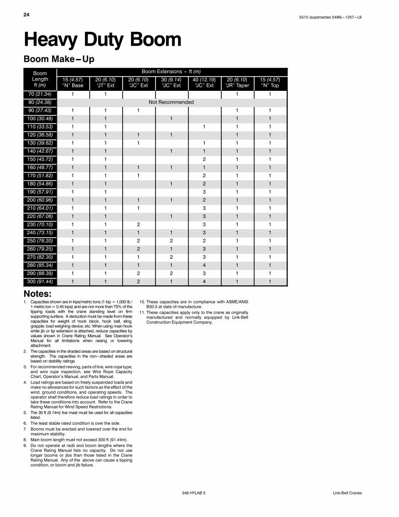
Attachment and OptionsHeavy Duty Boom70--300 ft (21.34---91.44m)
Basic Boom70 ft (21.34m) four ---piece design thatutilizes a 15 ft (4.57m)base section, 20 ft(6.10m)baseextension, 20 ft (6.10m) ta-pered extension, and 15 ft (4.57m) topsection with in --- line connecting pins on95 in (2.41m) wide and 80 in (2.03m)deep centers.S Boom foot on 56.50 in (1.44m) centersS 6 in (15.24cm) diameter tubular chordson base section and top section
S 5.25 in (13.34cm) diameter tubularchords on extensions
S Skywalk platformon 20 ft (6.10m)baseextension
S Offset head sheavesS Permanent standsmountedon topsec-tion to protect head machinery
S Seven 23 in (0.58m) root diameter poly-mide sheaves mounted on sealedanti --- friction bearings
S Tip extension and jib connecting lugson top section
S Mechanical boom angle indicator
Heavy Duty Boom ExtensionsThe following table provides the lengthsavailable and the suggested quantity to ob-tain maximum boom.
Heavy Duty TubeBoom Extensions Quantity For Max
Boomft m
“JC” Heavy Duty Boom
20 6.10 2
30 9.14 1
40 12.19 4
S Midpoint pendant connections are re-quired at 165 ft (50.29m) for boomlengths 250 ft (76.20m) through 300 ft(91.44m).
S Polyamide wear blocks on top of eachextension
S Appropriate length bar pendantsstored on extension
S Maximum tip height of 305 ft (92.96m)S Boom connecting pin storage on eachextension
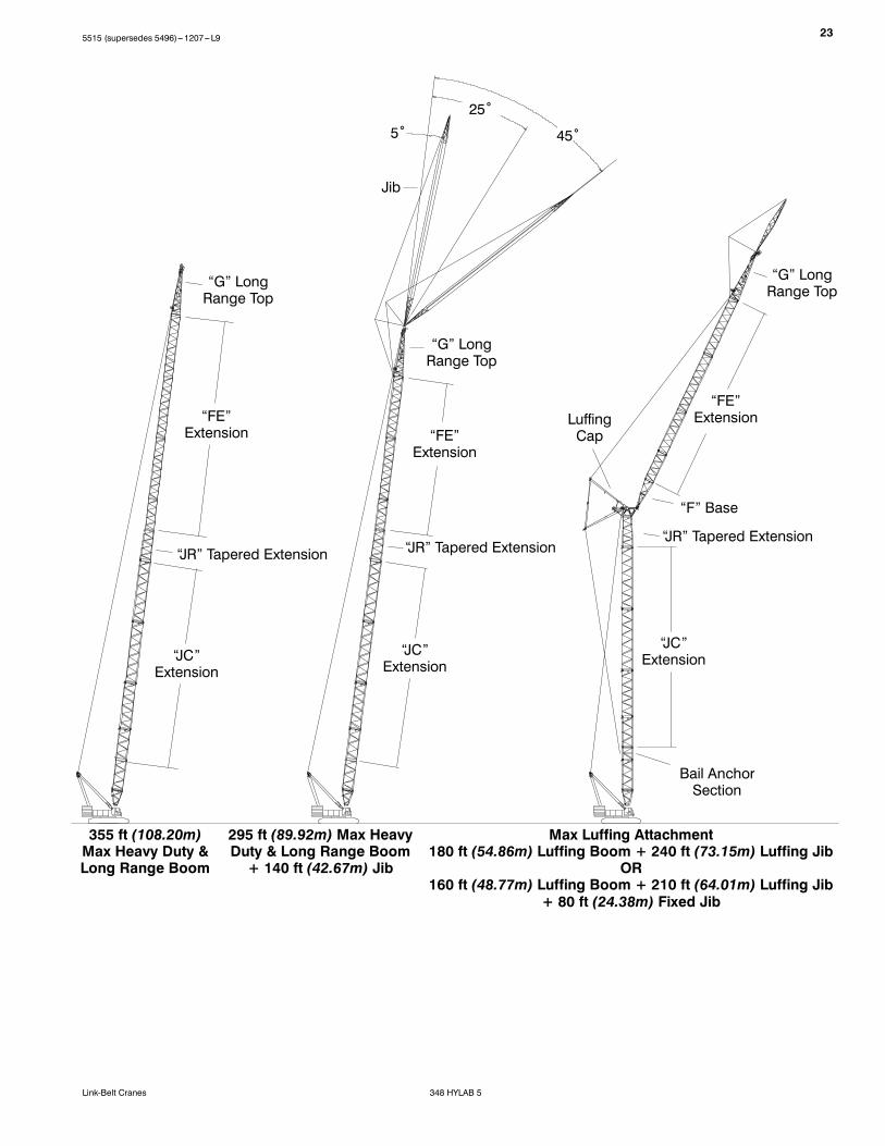
Long Range Boom85--355 ft (25.91---108.20m)
Basic Boom85 ft (25.91m) four ---piece design thatutilizes a 15 ft (4.57m)base section, 20 ft(6.10m)baseextension, 20 ft (6.10m) ta-pered extension, and 30 ft (9.14m) longrange top section with in --- line connect-ing pins on 80 in (2.03m) wide and 68 in(1.73m) deep centers.S Six 21 in (0.53m) root diameter poly-mide sheaves mounted on sealedanti --- friction bearings
S Tip extension and jib connecting lugson top section
S Long rangeboom is luffing jib for luffingattachment
Long Range Boom ExtensionsThe following table provides the lengthsavailable and the suggested quantity to ob-tain maximum boom.
Boom Extensions
ft m Quantity For MaxBoom
“JC” Heavy Duty Boom
20 6.10 1
30 9.14 1
40 12.19 2
“FE” Long Range Boom
10 3.05 1
20 6.10 1
30 9.14 1
40 12.19 2
S Midpoint pendant connections are re-quired at 165 ft (50.29m) for boomlengths 225 ft (68.58m) through 355 ft(108.20m).
S Polyamide wear blocks on top of eachextension
S Appropriate length bar pendantsstored on extension
S Maximum tip height of 360 ft (109.73m)S Boom connecting pin storage on eachextension
Jib40--140 ft (12.19---42.67m)
Basic Tube Jib40 ft (12.19m) two---piece design thatutilizes a 20 ft (6.10m) base section anda 20 ft (6.10m) top section with in --- lineconnecting pins on 48 in (1.22m) wideand 39 in (0.99m) deep centers.
JibExtensions Quantity For Max
Jibft m
20 6.10 5
S 3.00 in (7.62cm) diameter tubularchords
S One 23 in (0.58m) root diameter steelsheave mounted on sealed anti --- fric-tion bearings
S 20 ft (6.10) jib extensions are availableto provide jib lengths of 40---140 ft(12.19 ---42.67m) in 20 ft (6.10m) incre-ments
S Jib offset angles at 5˚, 25˚, and 45˚S The maximum tip height of tube boom+ jib [295 ft + 140 ft (89.92 + 42.67m)]is 435 ft (132.59m).
S Can be used as fixed jib on luffing at-tachment
Auxiliary Tip Extension5 ft (1.5m)
Designed to use in place of jib to provideclearance between working hoist lines.The extension is equipped with two poly-mide 21 in (0.53m) root diameter sheavesmounted on sealed anti --- friction bear-ings. Maximum capacity is 20 Tons(18.14mt).
55515 (supersedes 5496)---1207---L9
348 HYLAB 5Link-Belt Cranes
Luffing Boom130--200 ft (39.62---60.96m)
S Common base and extensions withheavy duty boom (“JC” boom only)
S 10 ft (3.05m) luffing extension requiredfor bail anchor
S Working angles of 90˚, 85˚, 80˚, 75˚,70˚, and 65˚
S Working lengths of 130 ft (39.62m) to200 ft (60.71m)
S Third drum becomes luffing jib hoistS Rear drum provides second load hoistS Designed for self ---assemblyS Luffing jib hoist bridle and bail can re-main reeved for crane transport
S Job site mobility with attachmentS Compact transport module
Luffing Boom ExtensionsThe following table provides the lengthsavailable and the suggested quantity toobtain the maximum luffing boom. Mid-point pendants are not required.
Luffing BoomExtensions Quantity For Max
Luffing Boomft m
“JC” Wall
20 6.10 1
30 9.14 1
40 12.19 2
Luffing Jib100--240 ft (30.48---73.15m)
Basic Luffing Jib100 ft (30.48m) basic luffing jib designutilizes a 20 ft (6.10m) luffing jib basesection, 50 ft (15.24m) of luffing jib ex-tensions, and a 30 ft (9.14m) top sectionwith in --- line connecting pins on 80 in(2.03m) wide and 68 in (1.73m) deepcenters.S Working lengths of 100 ft (30.48m) to240 ft (73.15m)
S Top section includes mounting lugs forfixed jib
S Six 21 in (0.53m) root diameter poly-mide luffing jib head sheaves mountedon anti --- friction bearings
S Two 23 in (0.58m) root diameter poly-mide luffing boom auxiliary headsheaves mounted on anti --- frictionbearings
S Pin---on nose wheelS Twelve---part luffing jib hoistS Appropriate length bar pendantsstored on extension
S The maximum boom length of luffingboom+ luffing jib [180 ft+240 ft (54.86+ 73.15m)] is 420 ft (128.02m).
Luffing Jib ExtensionsThe following table provides the lengthsavailable and the suggested quantity toobtain the maximum luffing jib. Midpointpendants are not required.
Luffing JibExtensions Quantity For Max
Luffing Jibft m
“FE” Wall
10 3.05 1
20 6.10 2
30 9.14 2
40 12.19 2
Note: Long range boom extensionsmake---up luffing jib.
S Polymide wear blocks on top of eachsection
S The maximum tip height is 417.3 ft(127.2m).
Fixed Jib80 ft (24.38m)
Basic Tube Jib80 ft (24.38m) design that utilizes a 20 ft(6.10m) base section, two 20 ft (6.10m)extensions, and a 20 ft (6.10m) top sec-tion with in --- line connecting pins on 48in (1.22m) wide and 39 in (0.99m) deepcenters.S Two 20 ft (6.10m) extensions availablefor 80 ft (24.38m) fixed jib.
S 3.00 in (7.62cm) diameter tubularchords
S One 23 in (0.58m) root diameter steelsheave mounted on sealed anti --- fric-tion bearings
S The maximum tip height of 446.2 ft(136.0m).
6 5515 (supersedes 5496)---1207---L9
348 HYLAB 5 Link-Belt Cranes
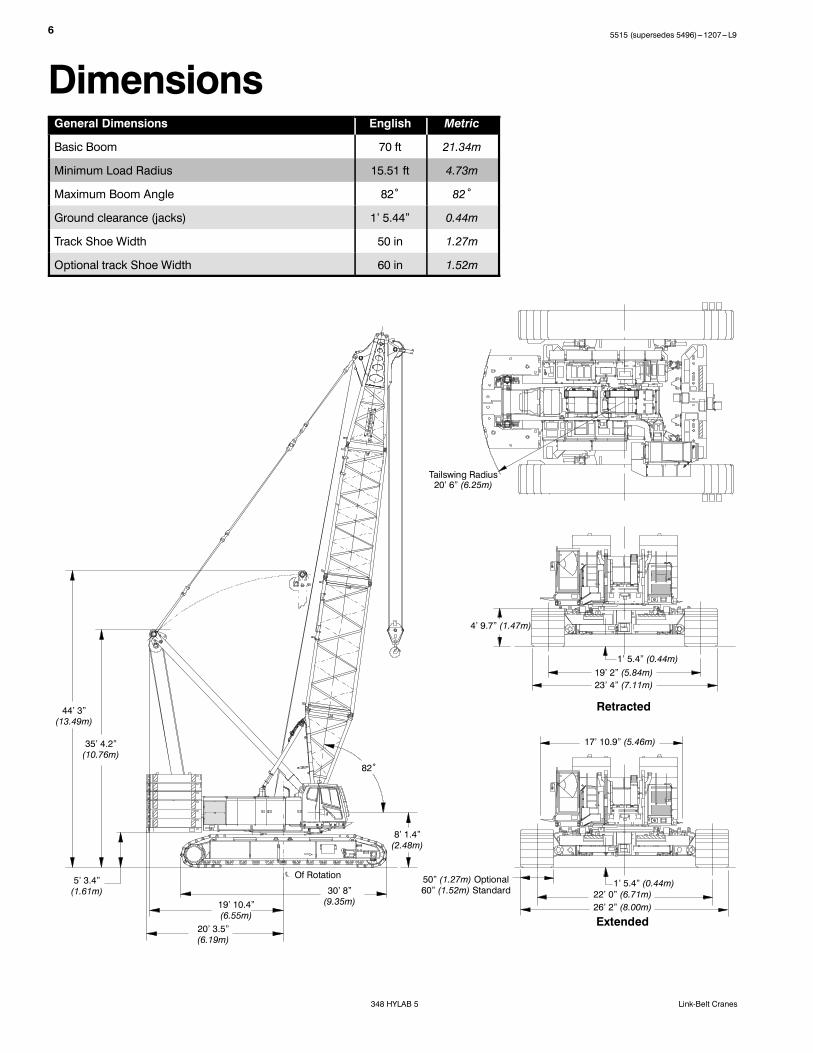
DimensionsGeneral Dimensions English Metric
Basic Boom 70 ft 21.34m
Minimum Load Radius 15.51 ft 4.73m
Maximum Boom Angle 82˚ 82˚
Ground clearance (jacks) 1’ 5.44” 0.44m
Track Shoe Width 50 in 1.27m
Optional track Shoe Width 60 in 1.52m
44’ 3”(13.49m)
35’ 4.2”(10.76m)
5’ 3.4”(1.61m)
20’ 3.5”(6.19m)
19’ 10.4”(6.55m)
30’ 8”(9.35m)
Of Rotation
8’ 1.4”(2.48m)
82˚
Tailswing Radius20’ 6” (6.25m)
4’ 9.7” (1.47m)
1’ 5.4” (0.44m)19’ 2” (5.84m)23’ 4” (7.11m)
17’ 10.9” (5.46m)
22’ 0” (6.71m)26’ 2” (8.00m)
1’ 5.4” (0.44m)
Retracted
Extended
50” (1.27m) Optional60” (1.52m) Standard
L 2
Number inside black circle “ ” = # of components
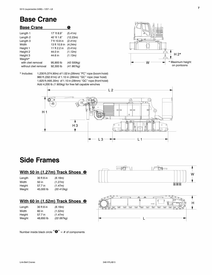
Base CraneLength 1 17’ ft 8.9” (5.41m)Length 2 40’ ft 1.6” (12.23m)Length 3 7 ft 10.9 in (2.41m)Width 13 ft 10.9 in (4.24m)Height 1 11 ft 2.2 in (3.41m)Height 2 44.0 in (1.12m)Height 3 44.6 in (1.13m)Weight*with ctwt removal 95,900 lb (43 500kg)without ctwt removal 92,300 lb (41 867kg)
* Includes: 1,230 ft (374.90m) of 1.02 in (26mm) “FC” rope (boomhoist)960 ft (292.61m) of 1.10 in (28mm) “GC” rope (rear hoist)1,625 ft (495.30m) of 1.10 in (28mm) “GC” rope (front hoist)Add 4,200 lb (1 905kg) for free fall capable winches
With 50 in (1.27m) Track ShoesLength 30 ft 8 in (8.16m)Width 50 in (1.27m)Height 57.7 in (1.47m)Weight 45,000 lb (20 412kg)
H 1
L
H
L 1
W
W
L 3
H 2*
* Maximum heighton pontoons
Base Crane
Side Frames
H 3
With 60 in (1.52m) Track ShoesLength 30 ft 8 in (8.16m)Width 60 in (1.52m)Height 57.7 in (1.47m)Weight 48,650 lb (22 067kg)
75515 (supersedes 5496)---1207---L9
348 HYLAB 5Link-Belt Cranes
8 5515 (supersedes 5496)---1207---L9
348 HYLAB 5 Link-Belt Cranes
H
H
H
Base CounterweightLength 8 ft 1 in (2.46m)Width 12 ft 11.1 in (3.94m)Height 4 ft 9.9 in (1.47m)Weight 36,128 lb (16 388kg)
Upper Counterweights W
L
Number inside black circle “ ” = # of components
#1 CounterweightLength 8 ft 2.4 in (2.5m)Width 6 ft 7.9 in (2.3m)Height 1 ft 7.9 in (0.5m)Weight 17,086 lb (8 101kg)
#2 CounterweightLength 8 ft 2.4 in (2.5m)Width 6 ft 7.9 in (2.3m)Height 1 ft 7.9 in (0.5m)Weight 16,755 lb (7 600kg)
#3 CounterweightLength 8 ft 2.4 in (2.5m)Width 4 ft 9.1 in (1.45m)Height 1 ft 7.1 in (0.48m)Weight 12,125 lb (5 499kg)
1
2
3
H
L
W
L
W
L
W
95515 (supersedes 5496)---1207---L9
348 HYLAB 5Link-Belt Cranes
Lower Counterweights
W
LH
Number inside black circle “ ” = # of components
Base CarbodyCounterweightLength 11 ft 6 in (3.51m)Width 4 ft 2.6 in (1.29m)Height 10 in (0.25m)Weight 14,770 lb (6 670kg)
Carbody CounterweightSlabsLength 6 ft 7.7 in (2.25m)Width 4 ft 2.6 in (1.29m)Height 1 ft 3.7 in (0.4m)WeightSlab 1 11,243 lb (5 100kg)Slab 2 11,464 lb (5 200kg)
W
L
H
L
W
H
Upper CounterweightConfigurations
A
AB
ABC
1
2
3
Base Slab
10 5515 (supersedes 5496)---1207---L9
348 HYLAB 5 Link-Belt Cranes
7’ 8.1”(2.34m)
40 ft (12.19m) ExtensionWeight: 6,552 lb (2 972kg)
80 in (2.03m) x 95 in (2.41m)Heavy Duty BoomExtensions “JC”Weights Include Pendants and Hardware
30 ft (9.14m) ExtensionWeight: 5,187 lb (2 353kg)
20 ft (6.10m) ExtensionWeight: 3,651 lb (1 656kg)
Boom
8’ 5.7”(2.58m) 20’ 5.8” (6.24m)
7’ 8.1”(2.34m)
8’ 5.7”(2.58m) 30’ 5.8” (9.29m)
7’ 8.1”(2.34m)
8’ 5.7”(2.58m) 40’ 5.8” (12.34m)
68 in (1.72m) x 80 in (2.03m)Long Range BoomExtensions “FE”Weights Include Pendants and Hardware
6’ 8.4”(2.04m)
7’ 2.4”(2.20m) 10’ 4.6” (3.17m)
10 ft (3.05m) ExtensionWeight: 1,338 lb (607kg)
6’ 8.4”(2.04m)
7’ 2.4”(2.20m) 20’ 4.6” (6.21m)
20 ft (6.10m) ExtensionWeight: 2,162 lb (981kg)
6’ 8.4”(2.04m)
7’ 2.4”(2.20m) 30’ 4.6” (9.26m)
30 ft (9.14m) ExtensionWeight: 2,992 lb (1 357kg)
6’ 8.4”(2.04m)
7’ 2.4”(2.20m) 40’ 4.6” (12.31m)
40 ft (12.19m) ExtensionWeight: 3,823 lb (1 734kg)
115515 (supersedes 5496)---1207---L9
348 HYLAB 5Link-Belt Cranes
15 ft (6.10m) Heavy Duty/Long Range BoomBase Section “N”Length 1 15 ft 9.5 in (4.81m)Length 2 16 ft 1.8 in (4.92m)Width 8 ft 6 in (2.59m)Deep 80 in (2.03m)Height 1 7 ft 6.3 in (2.29m)Height 2 7 ft 1 in (2.16m)Weight 6,350 lb (2 880kg)
LW
DH
Number inside black circle “ ” = # of components* --- Optional equipment
20 ft (6.10m) Heavy Duty/Long Range BoomTapered Extension “JR”Length 20 ft 5.5 in (6.24m)Width 8 ft 4.2 in (2.55m)Deep 80 in (2.03m)Height 7 ft 7.8 in (2.33m)Weight 5,044 lb (2 288kg)
D H
L W
20 ft (6.10m) Heavy Duty/Long Range BoomBase Extension “JT”Length 20 ft 5.8 in (6.24m)Width 8 ft 5.7 in (2.58m)Deep 80 in (2.03m)Height 7 ft 8.1 in (2.34m)Weight 4,126 lb (1 872kg)
W
DH1
H2
L2
L1
12 5515 (supersedes 5496)---1207---L9
348 HYLAB 5 Link-Belt Cranes
15 ft (4.57m) Heavy DutyBoom Top Section “N”Length 1 17 ft 5.3 in (5.32m)Length 2 17 ft 6.4 in (5.34m)Width 7 ft 2 in (2.18m)Deep 68 in (1.72m)Height 1 7 ft 5.4 in (2.27m)Height 2 7 ft 4.5 in (2.25m)Weight 7,526 lb (3 414kg)
D
L1
H1
W
Number inside black circle “ ” = # of components* --- Optional equipment
30 ft (9.14m) Long RangeBoom Top Section “G”Length 1 33 ft 10.8 in (10.33m)Length 2 33 ft 11.8 in (10.36m)Width 7 ft 0 in (2.03m)Deep 68 in (1.72m)Height 1 7 ft 2.4 in (2.19m)Height 1 7 ft 0.1 in (2.14m)Weight 5,072 lb (2 301kg)
L2
H2
L1
L2
H1
H2
D
W
135515 (supersedes 5496)---1207---L9
348 HYLAB 5Link-Belt Cranes
Number inside black circle “ ” = # of components* --- Optional equipment
20 ft (6.10m) Jib/FixedTop Section “E”*Length 22 ft 2.2 in (6.76m)Width 48 in (1.21m)Deep 39 in (0.99m)Height 4 ft 1.3 in (1.25m)Weight 1,755 lb (796kg)Weight includes jib top, 23 in (0.58m) head sheave,pendant links, ATB weight, and mounting hard-ware.
20 ft (6.10m) Jib/FixedBase Section “K”*Length 21 ft 2 in (6.41m)Width 48 in (1.21m)Deep 39 in (0.99m)Height 5 ft 10.4 in (1.79m)Weight 2,936 lb (1 332kg)Weight includes base section, strut, pendants, andmounting hardware.
Jib/Fixed Jib
L
H
20 ft (6.10m) Jib/FixedExtensions “EF”*Length 20 ft 3.5 in (6.19m)Width 48 in (1.21m)Deep 39 in (0.99m)Height 3 ft 7.9 in (1.11m)Weight 959 lb (435kg)Weights includes extension, pendants, wear bar,and mounting hardware.
D
L
DH
L
HD
W
14 5515 (supersedes 5496)---1207---L9
348 HYLAB 5 Link-Belt Cranes
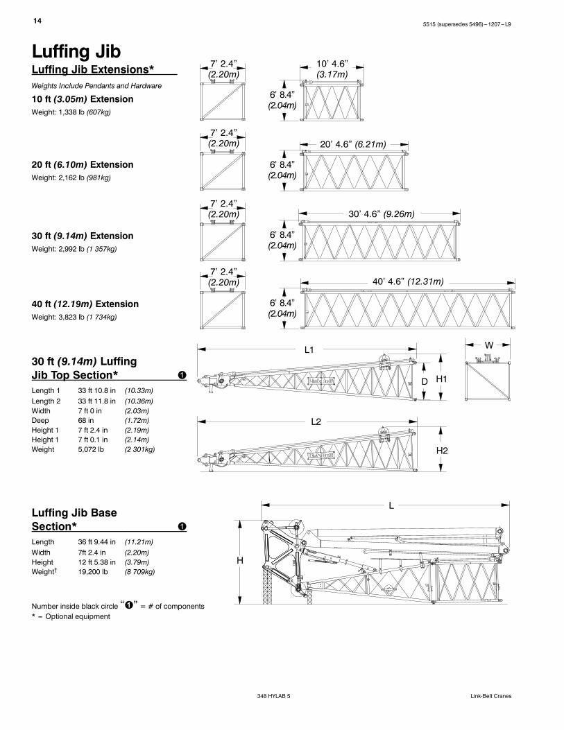
Luffing Jib Extensions*Weights Include Pendants and Hardware
30 ft (9.14m) ExtensionWeight: 2,992 lb (1 357kg)
10 ft (3.05m) ExtensionWeight: 1,338 lb (607kg)
20 ft (6.10m) ExtensionWeight: 2,162 lb (981kg)
30 ft (9.14m) LuffingJib Top Section*Length 1 33 ft 10.8 in (10.33m)Length 2 33 ft 11.8 in (10.36m)Width 7 ft 0 in (2.03m)Deep 68 in (1.72m)Height 1 7 ft 2.4 in (2.19m)Height 1 7 ft 0.1 in (2.14m)Weight 5,072 lb (2 301kg)
Number inside black circle “ ” = # of components* --- Optional equipment
Luffing Jib
Luffing Jib BaseSection*Length 36 ft 9.44 in (11.21m)Width 7ft 2.4 in (2.20m)Height 12 ft 5.38 in (3.79m)Weight† 19,200 lb (8 709kg)
40 ft (12.19m) ExtensionWeight: 3,823 lb (1 734kg)
20’ 4.6” (6.21m)
30’ 4.6” (9.26m)
40’ 4.6” (12.31m)
10’ 4.6”(3.17m)
7’ 2.4”(2.20m)
7’ 2.4”(2.20m)
7’ 2.4”(2.20m)
7’ 2.4”(2.20m)
L1
L2
H1
H2
D
W
6’ 8.4”(2.04m)
6’ 8.4”(2.04m)
6’ 8.4”(2.04m)
6’ 8.4”(2.04m)
L
H
155515 (supersedes 5496)---1207---L9
348 HYLAB 5Link-Belt Cranes
300 Ton (272.2mt) 7---SheaveHook Block*Width1 31.00 in (0.79m)Width2 28.75 in (0.73m)Width3 37.25 in (0.95m)Height 96.25 in (2.44m)Weight 6,436 lb (2 919kg)
Hook Blocks
Number inside black circle “ ” = # of components* --- Optional equipment
60 Ton (54.4mt) 2---SheaveHook Block*Width1 15.50 in (0.39m)Width2 28.75 in (0.73m)Width3 18.75 in (0.48m)Height 67.00 in (1.70m)Weight 1,637 lb (742kg)
250 Ton (226.8mt) 6---SheaveHook Block*Width1 25.35 in (0.64m)Width2 35.25 in (0.90m)Width3 34.75 in (0.88m)Height 95.35 in (2.42m)Weight 4,932 lb (2 237kg)
W1 W2
W3
Hook Balls20 Ton (18.1mt) Non---SwivelHook Ball*Width 21.75 in (0.55m)Height 39.00 in (0.99m)Weight 1,214 lb (551kg)
W
H
H
W1 W2
W3
H
W1 W2
W3
H
165 Ton (149.7mt) 5---SheaveHook Block*Width1 22.00 in (0.56m)Width2 28.75 in (0.73m)Width3 28.25 in (0.72m)Height 81.50 in (2.07m)Weight 3,611 lb (1 638kg)
W1 W2
W3
H
16 5515 (supersedes 5496)---1207---L9
348 HYLAB 5 Link-Belt Cranes
Assembly Diagram
Working WeightsBased on basic crane including Isuzu BB---6W1XQB---01 diesel engine, turntable bearing, indepen-dent hydraulic powered drums, boom hoist limit device, independent hydraulic swing and travel,counterweight, swing brake, drum rotation indicators, crawler lower with 50 in (1.27m) track shoes,sealed carrier rollers, catwalks, and hydraulic boom foot pin removal. The following are also in-cluded:
A+A Ctwt AB+A Ctwt ABC+A Ctwt
lb (kg) lb (kg) lb (kg)
Lifting crane --- Base machine with live mast, 1,230 ft (374.9m) main rope, 940 ft (286.5m) auxiliaryrope, 70 ft (21.3m) basic heavy duty boom, and 50 in (1.27m) side frames.
354,888 lb(160 974kg)
456,988 lb(207 286kg)
505,688 lb(229 376kg)
Ground Bearing Pressurepsi 10.5 13.5 15.0
kg/cm2 0.74 0.95 1.05
175515 (supersedes 5496)---1207---L9
348 HYLAB 5Link-Belt Cranes
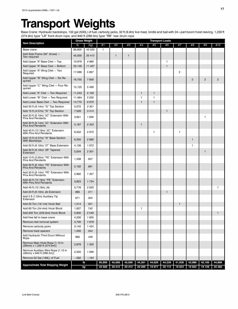
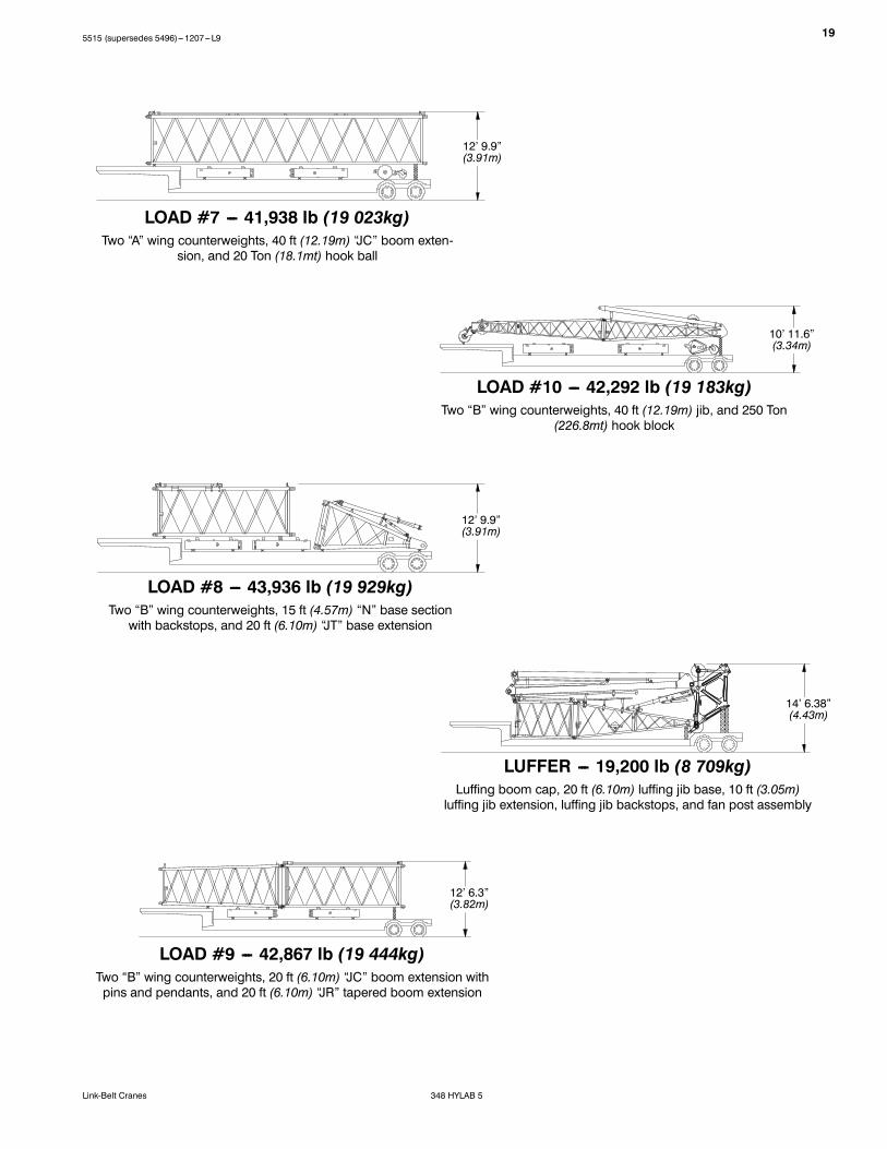
Transport WeightsBase Crane: Hydraulic backstops, 132 gal (500L) of fuel, carbody jacks, 32 ft (9.8m) live mast, bridle and bail with 24---part boom hoist reeving, 1,230 ft(374.9m) type “LB” front drum rope, and 940 ft (286.5m) type “RB” rear drum rope.
Notes:1. Capacities shownare in kips/metric tons (1 kip =1,000 lb /1metric ton=0.45 kips) and are not more than 75% of thetipping loads with the crane standing level on firmsupporting surface. A deductionmust bemade from thesecapacities for weight of hook block, hook ball, sling,grapple, loadweighing device, etc. When using main hookwhile jib or tip extension is attached, reduce capacities byvalues shown in Crane Rating Manual. See Operator’sManual for all limitations when raising or loweringattachment.
2. The capacities in the shaded areas are based on structuralstrength. The capacities in the non---shaded areas arebased on stability ratings.
3. For recommended reeving, parts of line,wire rope type,and wire rope inspection, see Wire Rope CapacityChart, Operator’s Manual, and Parts Manual.
4. Load ratings are based on freely suspended loads andmake no allowances for such factors as the effect of thewind, ground conditions, and operating speeds. Theoperator shall therefore reduce load ratings in order totake these conditions into account. Refer to the CraneRating Manual for Wind Speed Restrictions.
5. The 30 ft (9.14m) live mast must be used for all capacitieslisted.
6. The least stable rated condition is over the side.7. Booms must be erected and lowered over the end formaximum stability.
8. Main boom length must not exceed 300 ft (91.44m).9. Do not operate at radii and boom lengths where theCrane Rating Manual lists no capacity. Do not uselonger booms or jibs than those listed in the CraneRating Manual. Any of the above can cause a tippingcondition, or boom and jib failure.
10. These capacities are in compliance with ASME/ANSIB30.5 at date of manufacture.
11. These capacities apply only to the crane as originallymanufactured and normally equipped by Link-BeltConstruction Equipment Company.
255515 (supersedes 5496)---1207---L9
348 HYLAB 5Link-Belt Cranes
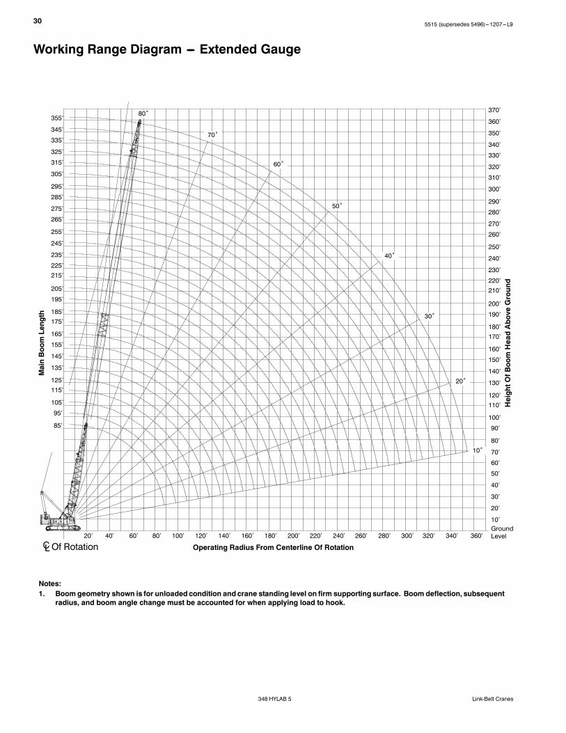
Working Range Diagram --- Extended Gauge
310’
300’
290’
280’
270’
260’
250’
240’
230’
220’
210’
200’
190’
180’
170’
160’
150’
140’
130’
120’
110’
100’
90’
80’
70’
60’
50’
40’
30’
20’
10’
GroundLevel
300’
290’
280’
270’
260’
250’
240’
230’
220’
210’
200’
190’
180’
170’
160’
150’
140’
130’
120’
110’
100’
90’
80’
70’
10’
10˚
20˚
30˚
40˚
50˚
60˚
70˚
80˚
Notes:1. Boom geometry shown is for unloaded condition and crane standing level on firm supporting surface. Boom deflection, subsequent
radius, and boom angle change must be accounted for when applying load to hook.
Load Chart --- Extended GaugeHeavy Duty Boom With Heavy Duty Top --- Extended Gauge (22’) --- 360˚ Rotation
ABC + A [221,700 + 75,000 lb (100.3 + 34.0mt)] Ctwt[All capacities are listed in kips (mt)]
LoadRadiusft (m)
Boom Length ft (m)LoadRadiusft (m)70
(21.34)90
(27.43)110(33.53)
130(39.62)
150(45.72)
170(51.82)
190(57.91)
210(64.01)
230(70.10)
250(76.20)
270(82.30)
290(88.39)
300(91.44)
16(4.88)
600.0(272.7)
16(4.88)
17(5.18)
569.0(258.6)
17(5.18)
18(5.49)
539.8(245.4)
18(5.49)
19(5.79)
513.5(233.4)
510.1(231.9)
19(5.79)
20(6.10)
489.4(222.5)
486.4(221.1)
20(6.10)
30(9.14)
331.2(150.5)
329.8(149.9)
327.8(149.0)
325.5(148.0)
322.9(146.8)
308.7(140.3)
30(9.14)
40(12.19)
235.1(106.9)
235.6(107.1)
235.5(107.0)
235.2(106.9)
234.8(106.7)
234.4(106.5)
233.9(106.3)
225.3(102.4)
186.9(85.0)
153.4(69.7)
128.5(58.4)
40(12.19)
50(15.24)
170.9(77.7)
171.2(77.8)
171.0(77.7)
170.6(77.5)
170.0(77.3)
169.4(77.0)
168.7(76.7)
168.0(76.4)
167.2(76.0)
151.5(68.9)
126.9(57.7)
105.3(47.9)
97.5(44.3)
50(15.24)
60(18.29)
132.9(60.4)
133.3(60.6)
133.0(60.5)
132.4(60.2)
131.8(59.9)
131.0(59.5)
130.2(59.2)
129.4(58.8)
128.6(58.5)
127.8(58.1)
118.2(53.7)
100.0(45.5)
92.6(42.1)
60(18.29)
70(21.34)
107.5(48.9)
108.1(49.1)
107.8(49.0)
107.2(48.7)
106.5(48.4)
105.7(48.0)
104.9(47.7)
104.0(47.3)
103.1(46.9)
102.1(46.4)
101.2(46.0)
92.5(42.0)
84.5(38.4)
70(21.34)
80(24.38)
90.1(41.0)
89.9(40.9)
89.4(40.6)
88.6(40.3)
87.8(39.9)
86.9(39.5)
85.9(39.0)
85.0(38.6)
83.9(38.1)
82.9(37.7)
82.0(37.3)
75.5(34.3)
80(24.38)
90(27.43)
76.5(34.8)
76.5(34.8)
76.0(34.5)
75.2(34.2)
74.3(33.8)
73.4(33.4)
72.4(32.9)
71.5(32.5)
70.3(32.0)
69.3(31.5)
68.3(31.0)
67.8(30.8)
90(27.43)
100(30.48)
66.0(30.0)
65.6(29.8)
64.8(29.5)
63.9(29.0)
63.0(28.6)
62.0(28.2)
61.0(27.7)
59.8(27.2)
58.7(26.7)
57.7(26.2)
57.2(26.0)
100(30.48)
110(33.53)
57.5(26.1)
57.2(26.0)
56.5(25.7)
55.6(25.3)
54.7(24.9)
53.7(24.4)
52.6(23.9)
51.3(23.3)
50.3(22.9)
49.3(22.4)
48.7(22.1)
110(33.53)
120(36.58)
50.3(22.9)
49.7(22.6)
48.8(22.2)
47.9(21.8)
46.8(21.3)
45.8(20.8)
44.5(20.2)
43.4(19.7)
42.4(19.3)
41.8(19.0)
120(36.58)
130(39.62)
44.5(20.2)
44.0(20.0)
43.1(19.6)
42.2(19.2)
41.2(18.7)
40.1(18.2)
38.8(17.6)
37.7(17.1)
36.6(16.6)
36.1(16.4)
130(39.62)
140(42.67)
39.1(17.8)
38.3(17.4)
37.4(17.0)
36.4(16.5)
35.3(16.0)
33.9(15.4)
32.8(14.9)
31.8(14.5)
31.2(14.2)
140(42.67)
150(45.72)
34.8(15.8)
34.1(15.5)
33.2(15.1)
32.2(14.6)
31.2(14.2)
29.8(13.5)
28.7(13.0)
27.6(12.5)
27.0(12.3)
150(45.72)
160(48.77)
30.5(13.9)
29.6(13.5)
28.6(13.0)
27.6(12.5)
26.2(11.9)
25.1(11.4)
24.0(10.9)
23.4(10.6)
160(48.77)
170(51.82)
27.2(12.4)
26.5(12.0)
25.5(11.6)
24.4(11.1)
23.0(10.5)
21.9(10.0)
20.8(9.5)
20.3(9.2)
170(51.82)
180(54.86)
23.6(10.7)
22.7(10.3)
21.7(9.9)
20.2(9.2)
19.1(8.7)
18.0(8.2)
17.5(8.0)
180(54.86)
190(57.91)
21.0(9.5)
20.2(9.2)
19.2(8.7)
17.7(8.0)
16.7(7.6)
15.6(7.1)
15.0(6.8)
190(57.91)
200(60.96)
17.9(8.1)
16.9(7.7)
15.5(7.0)
14.4(6.5)
13.3(6.0)
12.8(5.8)
200(60.96)
220(67.06)
13.0(5.9)
11.6(5.3)
10.6(4.8)
9.5(4.3)
8.9(4.0)
220(67.06)
240(73.15)
8.4(3.8)
7.4(3.4)
6.3(2.9)
5.8(2.6)
240(73.15)
260(79.25)
4.6(2.1)
3.6(1.6)
3.1(1.4)
260(79.25)
270(82.30)
4.6(2.1)
3.6(1.6)
270(82.30)
This material is supplied for reference use only. Operator must refer to in---cab Crane Rating Manual and Operator’s Manual to determine allowablecrane lifting capacities and assembly and operating procedures.
275515 (supersedes 5496)---1207---L9
348 HYLAB 5Link-Belt Cranes
Working Range Diagram --- Retracted Gauge
270’
260’
250’
240’
230’
220’
210’
200’
190’
180’
170’
160’
150’
140’
130’
120’
110’
100’
90’
80’
70’
60’
50’
40’
30’
20’
10’
GroundLevel
260’
250’
240’
230’
220’
210’
200’
190’
180’
170’
160’
150’
140’
130’
10˚
20˚
30˚
40˚
50˚
60˚
70˚
80˚
Notes:1. Boom geometry shown is for unloaded condition and crane standing level on firm supporting surface. Boom deflection, subsequent
radius, and boom angle change must be accounted for when applying load to hook.
Heavy Duty Boom With Heavy Duty Top --- Retracted Gauge (19’ 2”) --- 360˚ Rotation[All capacities are listed in kips (mt)]
LoadRadiusft (m)
Boom Length ft (m)
LoadRadiusft (m)
AB + A [172,150 + 75,000 lb (78.1 + 34.0mt)] Ctwt ABC + A [221,700 + 75,000 lb (100.3 + 34.0mt)] Ctwt
70(21.34)
90(27.43)
110(33.53)
130(39.62)
150(45.72)
170(51.82)
190(57.91)
210(64.01)
230(70.10)
250(76.20)
270(82.30)
290(88.39)
300(91.44)
16(4.88)
561.7(255.3)
16(4.88)
17(5.18)
531.4(241.5)
17(5.18)
18(5.49)
504.1(229.1)
18(5.49)
19(5.79)
479.4(217.9)
476.4(216.5)
19(5.79)
20(6.10)
456.9(207.7)
454.2(206.5)
20(6.10)
30(9.14)
268.7(122.1)
269.3(122.4)
269.5(122.5)
269.4(122.5)
269.3(122.4)
308.7(140.3)
30(9.14)
40(12.19)
175.3(79.7)
175.6(79.8)
175.4(79.7)
175.1(79.6)
174.6(79.4)
205.6(93.5)
205.0(93.2)
204.4(92.9)
186.9(85.0)
153.4(69.7)
128.5(58.4)
40(12.19)
50(15.24)
128.3(58.3)
128.5(58.4)
128.2(58.3)
127.7(58.0)
127.0(57.7)
150.0(68.2)
149.3(67.9)
148.5(67.5)
147.7(67.1)
147.1(66.9)
126.9(57.7)
105.3(47.9)
97.5(44.3)
50(15.24)
60(18.29)
99.8(45.4)
100.1(45.5)
99.8(45.4)
99.2(45.1)
98.4(44.7)
116.6(53.0)
115.8(52.6)
114.9(52.2)
114.0(51.8)
113.2(51.5)
112.3(51.0)
100.0(45.5)
92.6(42.1)
60(18.29)
70(21.34)
80.5(36.6)
81.1(36.9)
80.7(36.7)
80.1(36.4)
79.3(36.0)
94.3(42.9)
93.4(42.5)
92.5(42.0)
91.5(41.6)
90.5(41.1)
89.6(40.7)
88.6(40.3)
84.5(38.4)
70(21.34)
80(24.38)
67.3(30.6)
67.1(30.5)
66.4(30.2)
65.7(29.9)
78.3(35.6)
77.4(35.2)
76.4(34.7)
75.4(34.3)
74.3(33.8)
73.3(33.3)
72.3(32.9)
71.8(32.6)
80(24.38)
90(27.43)
56.7(25.8)
56.7(25.8)
56.2(25.5)
55.4(25.2)
66.3(30.1)
65.4(29.7)
64.4(29.3)
63.4(28.8)
62.2(28.3)
61.1(27.8)
60.1(27.3)
59.6(27.1)
90(27.43)
100(30.48)
48.6(22.1)
48.1(21.9)
47.3(21.5)
57.0(25.9)
56.0(25.5)
55.0(25.0)
54.0(24.5)
52.7(24.0)
51.6(23.5)
50.6(23.0)
50.1(22.8)
100(30.48)
110(33.53)
41.9(19.0)
41.6(18.9)
40.9(18.6)
49.5(22.5)
48.5(22.0)
47.5(21.6)
46.4(21.1)
45.1(20.5)
44.0(20.0)
43.0(19.5)
42.4(19.3)
110(33.53)
120(36.58)
36.2(16.5)
35.6(16.2)
43.3(19.7)
42.3(19.2)
41.3(18.8)
40.2(18.3)
38.9(17.7)
37.8(17.2)
36.7(16.7)
36.2(16.5)
120(36.58)
130(39.62)
31.6(14.4)
31.1(14.1)
38.2(17.4)
37.2(16.9)
36.2(16.5)
35.1(16.0)
33.7(15.3)
32.6(14.8)
31.5(14.3)
31.0(14.1)
130(39.62)
140(42.67)
27.2(12.4)
33.8(15.4)
32.8(14.9)
31.8(14.5)
30.7(14.0)
29.3(13.3)
28.2(12.8)
27.1(12.3)
26.5(12.0)
140(42.67)
150(45.72)
23.8(10.8)
30.0(13.6)
29.0(13.2)
28.0(12.7)
26.9(12.2)
25.5(11.6)
24.4(11.1)
23.3(10.6)
22.7(10.3)
150(45.72)
160(48.77)
26.6(12.1)
25.8(11.7)
24.7(11.2)
23.7(10.8)
22.2(10.1)
21.1(9.6)
20.0(9.1)
19.5(8.9)
160(48.77)
170(51.82)
23.6(10.7)
22.8(10.4)
21.9(10.0)
20.8(9.5)
19.4(8.8)
18.3(8.3)
17.1(7.8)
16.6(7.5)
170(51.82)
180(54.86)
20.2(9.2)
19.3(8.8)
18.3(8.3)
16.8(7.6)
15.7(7.1)
14.6(6.6)
14.0(6.4)
180(54.86)
190(57.91)
17.8(8.1)
17.0(7.7)
16.0(7.3)
14.5(6.6)
13.4(6.1)
12.3(5.6)
11.7(5.3)
190(57.91)
200(60.96)
14.9(6.8)
13.9(6.3)
12.5(5.7)
11.4(5.2)
10.3(4.7)
9.7(4.4)
200(60.96)
220(67.06)
10.4(4.7)
8.9(4.0)
7.9(3.6)
6.8(3.1)
6.2(2.8)
220(67.06)
240(73.15)
5.9(2.7)
4.9(2.2)
3.8(1.7)
3.3(1.5)
240(73.15)
250(76.20)
4.5(2.0)
3.6(1.6)
2.5(1.1)
2.0(0.9)
250(76.20)
260(79.25)
2.4(1.1)
260(79.25)
This material is supplied for reference use only. Operator must refer to in---cab Crane Rating Manual and Operator’s Manual to determine allowablecrane lifting capacities and assembly and operating procedures.
295515 (supersedes 5496)---1207---L9
348 HYLAB 5Link-Belt Cranes
Long Range BoomBoom Make---Up
BoomLengthft (m)
Boom Extensions --- ft (m)
15 (4.57)“N” Base
20 (6.10)“JT” Base Ext
20 (6.10)“JC” Ext
30 (9.14)“JC” Ext
40(12.19)“JC” Ext
20 (6.10)“JR” Tapered
10 (3.05)“FE” Ext
20 (6.10)“FE” Ext
30 (9.14)“FE” Ext
40(12.19)“FE” Ext
30 (9.14)“G” Top
85 (25.91) 1 1 1 1
95 (28.96) Not Recommended
105 (32.00) 1 1 1 1 1
115 (35.05) 1 1 1 1 1
125 (38.10) 1 1 1 1 1
135 (41.15) 1 1 1 1 1 1
145 (44.20) 1 1 1 1 1 1
155 (47.24) 1 1 1 1 1 1
165 (50.29) 1 1 2 1 1
175 (53.34) 1 1 1 1 1 1 1
185 (56.39) 1 1 1 2 1 1
195 (59.44) 1 1 1 2 1 1
205 (62.48) Not Recommended
215 (65.53) 1 1 1 1 2 1 1
225 (68.58) 1 1 1 1 2 1 1 1
235 (71.63) 1 1 1 1 2 1 1 1
245 (74.68) 1 1 1 1 2 1 1 1
255 (77.72) 1 1 1 1 2 1 1 1
265 (80.77) 1 1 1 1 2 1 1 1 1
275 (83.82) 1 1 1 1 2 1 1 1 1
285 (86.87) 1 1 1 1 2 1 1 1 1
295 (89.92) 1 1 1 1 2 1 2 1
305 (92.96) 1 1 1 1 2 1 1 2 1
315 (96.01) 1 1 1 1 2 1 1 2 1
325 (99.06) 1 1 1 1 2 1 1 2 1
335 (102.11) 1 1 1 1 2 1 1 1 2 1
345 (105.16) 1 1 1 1 2 1 1 1 2 1
355 (108.20) 1 1 1 1 2 1 1 1 1 2 1
Notes:1. Capacities shownare in kips/metric tons (1 kip =1,000 lb /1metric ton=0.45 kips) and are not more than 75% of thetipping loads with the crane standing level on firmsupporting surface. A deductionmust bemade from thesecapacities for weight of hook block, hook ball, sling,grapple, loadweighing device, etc. When using main hookwhile jib or tip extension is attached, reduce capacities byvalues shown in Crane Rating Manual. See Operator’sManual for all limitations when raising or loweringattachment.
2. The capacities in the shaded areas are based on structuralstrength. The capacities in the non---shaded areas arebased on stability ratings.
3. For recommended reeving, parts of line,wire rope type,and wire rope inspection, see Wire Rope CapacityChart, Operator’s Manual, and Parts Manual.
4. Load ratings are based on freely suspended loads andmake no allowances for such factors as the effect of thewind, ground conditions, and operating speeds. Theoperator shall therefore reduce load ratings in order totake these conditions into account. Refer to the CraneRating Manual for Wind Speed Restrictions.
5. The 30 ft (9.14m) live mast must be used for all capacitieslisted.
6. The least stable rated condition is over the side.7. Booms must be erected and lowered over the end formaximum stability.
8. Main boom length must not exceed 355 ft (108.20m).9. Do not operate at radii and boom lengths where theCrane Rating Manual lists no capacity. Do not uselonger booms or jibs than those listed in the Crane
Rating Manual. Any of the above can cause a tippingcondition, or boom and jib failure.
10. These capacities are in compliance with ASME/ANSIB30.5 at date of manufacture.
11. These capacities apply only to the crane as originallymanufactured and normally equipped by Link-BeltConstruction Equipment Company.
30 5515 (supersedes 5496)---1207---L9
348 HYLAB 5 Link-Belt Cranes
Working Range Diagram --- Extended Gauge
270’
260’
250’
240’
230’
220’210’
200’
190’
180’170’
160’
150’
140’
130’
120’110’
100’
90’
80’
70’
60’
50’
40’
30’
20’
10’GroundLevel
10˚
20˚
30˚
40˚
50˚
60˚
70˚
80˚
Notes:1. Boom geometry shown is for unloaded condition and crane standing level on firm supporting surface. Boom deflection, subsequent
radius, and boom angle change must be accounted for when applying load to hook.
Load Chart --- Extended GaugeLong Range Top --- Extended Gauge (22’) --- 360˚ RotationABC + A [221,700 + 75,000 lb (100.3 + 34.0mt)] Ctwt
[All capacities are listed in kips (mt)]
LoadRadiusft (m)
Boom Length ft (m)LoadRadiusft (m)85
(25.91)105(32.00)
125(38.10)
145(44.20)
165(50.29)
185(56.39)
205(62.48)
225(68.58)
245(74.68)
265(80.77)
285(86.87)
305(92.96)
325(99.06)
345(105.2)
355(108.2)
17(5.18)
302.2(137.4)
17(5.18)
18(5.49)
296.5(134.8)
18(5.49)
19(5.79)
290.9(132.2)
19(5.79)
20(6.10)
282.7(128.5)
272.5(123.9)
20(6.10)
25(7.62)
259.8(118.1)
248.6(113.0)
237.0(107.7)
229.9(104.5)
25(7.62)
30(9.14)
237.8(108.1)
226.9(103.1)
217.7(99.0)
209.8(95.4)
200.2(91.0)
30(9.14)
35(10.67)
221.5(100.7)
209.9(95.4)
198.0(90.0)
190.8(86.7)
183.9(83.6)
177.2(80.5)
170.6(77.5)
35(10.67)
40(12.19)
207.6(94.4)
192.8(87.6)
184.4(83.8)
177.1(80.5)
170.1(77.3)
163.9(74.5)
155.1(70.5)
138.8(63.1)
129.6(58.9)
40(12.19)
50(15.24)
175.1(79.6)
169.3(77.0)
157.9(71.8)
151.0(68.6)
145.1(66.0)
139.3(63.3)
134.2(61.0)
117.5(53.4)
113.4(51.5)
115.6(52.5)
89.1(40.5)
80.7(36.7)
50(15.24)
60(18.29)
137.3(62.4)
137.2(62.4)
136.7(62.1)
133.1(60.5)
127.4(57.9)
119.7(54.4)
114.9(52.2)
102.8(46.7)
102.4(46.5)
109.1(49.6)
84.4(38.4)
76.4(34.7)
61.9(28.1)
52.5(23.9)
47.4(21.5)
60(18.29)
70(21.34)
112.2(51.0)
112.2(51.0)
111.7(50.8)
111.0(50.5)
110.2(50.1)
105.5(48.0)
100.6(45.7)
90.3(41.0)
91.9(41.8)
99.2(45.1)
76.0(34.5)
70.7(32.1)
57.9(26.3)
49.4(22.5)
44.7(20.3)
70(21.34)
80(24.38)
94.4(42.9)
94.4(42.9)
93.9(42.7)
93.2(42.4)
92.4(42.0)
91.5(41.6)
88.6(40.3)
76.8(34.9)
78.6(35.7)
89.5(40.7)
71.0(32.3)
64.7(29.4)
53.7(24.4)
45.7(20.8)
37.9(17.2)
80(24.38)
90(27.43)
81.1(36.9)
80.6(36.6)
79.9(36.3)
79.1(36.0)
78.2(35.5)
76.2(34.6)
67.9(30.9)
70.3(32.0)
76.0(34.5)
66.3(30.1)
59.1(26.9)
50.1(22.8)
42.4(19.3)
35.1(16.0)
90(27.43)
100(30.48)
70.6(32.1)
70.3(32.0)
69.6(31.6)
68.7(31.2)
67.8(30.8)
66.8(30.4)
60.2(27.4)
63.0(28.6)
65.6(29.8)
62.4(28.4)
53.7(24.4)
46.6(21.2)
36.5(16.6)
32.8(14.9)
100(30.48)
110(33.53)
62.0(28.2)
61.3(27.9)
60.5(27.5)
59.5(27.0)
58.5(26.6)
53.8(24.5)
56.5(25.7)
57.2(26.0)
56.9(25.9)
49.0(22.3)
43.7(19.9)
34.1(15.5)
30.6(13.9)
110(33.53)
120(36.58)
55.1(25.0)
54.5(24.8)
53.7(24.4)
52.8(24.0)
51.8(23.5)
48.1(21.9)
50.7(23.0)
50.4(22.9)
50.1(22.8)
44.5(20.2)
38.2(17.4)
32.0(14.5)
28.5(13.0)
120(36.58)
130(39.62)
48.9(22.2)
48.1(21.9)
47.2(21.5)
46.1(21.0)
41.4(18.8)
45.0(20.5)
44.7(20.3)
44.4(20.2)
37.6(17.1)
36.0(16.4)
29.8(13.5)
26.5(12.0)
130(39.62)
140(42.67)
44.0(20.0)
43.3(19.7)
42.4(19.3)
41.4(18.8)
35.8(16.3)
40.2(18.3)
39.9(18.1)
39.6(18.0)
34.4(15.6)
34.1(15.5)
27.7(12.6)
24.7(11.2)
140(42.67)
150(45.72)
39.2(17.8)
38.3(17.4)
37.3(17.0)
31.1(14.1)
34.1(15.5)
35.8(16.3)
35.5(16.1)
31.4(14.3)
31.6(14.4)
26.0(11.8)
23.1(10.5)
150(45.72)
This material is supplied for reference use only. Operator must refer to in---cab Crane Rating Manual and Operator’s Manual to determine allowablecrane lifting capacities and assembly and operating procedures.
32 5515 (supersedes 5496)---1207---L9
348 HYLAB 5 Link-Belt Cranes
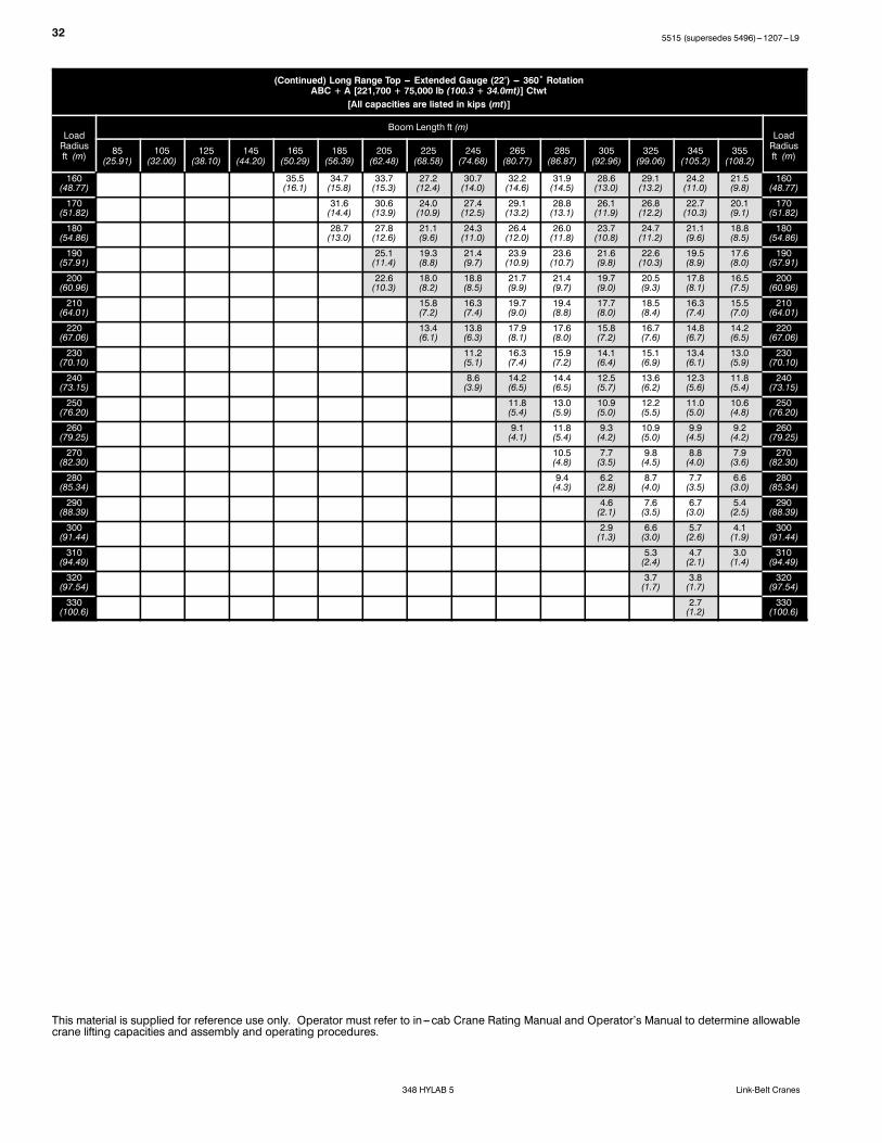
(Continued) Long Range Top --- Extended Gauge (22’) --- 360˚ RotationABC + A [221,700 + 75,000 lb (100.3 + 34.0mt)] Ctwt
[All capacities are listed in kips (mt)]
LoadRadiusft (m)
Boom Length ft (m)LoadRadiusft (m)85
(25.91)105(32.00)
125(38.10)
145(44.20)
165(50.29)
185(56.39)
205(62.48)
225(68.58)
245(74.68)
265(80.77)
285(86.87)
305(92.96)
325(99.06)
345(105.2)
355(108.2)
160(48.77)
35.5(16.1)
34.7(15.8)
33.7(15.3)
27.2(12.4)
30.7(14.0)
32.2(14.6)
31.9(14.5)
28.6(13.0)
29.1(13.2)
24.2(11.0)
21.5(9.8)
160(48.77)
170(51.82)
31.6(14.4)
30.6(13.9)
24.0(10.9)
27.4(12.5)
29.1(13.2)
28.8(13.1)
26.1(11.9)
26.8(12.2)
22.7(10.3)
20.1(9.1)
170(51.82)
180(54.86)
28.7(13.0)
27.8(12.6)
21.1(9.6)
24.3(11.0)
26.4(12.0)
26.0(11.8)
23.7(10.8)
24.7(11.2)
21.1(9.6)
18.8(8.5)
180(54.86)
190(57.91)
25.1(11.4)
19.3(8.8)
21.4(9.7)
23.9(10.9)
23.6(10.7)
21.6(9.8)
22.6(10.3)
19.5(8.9)
17.6(8.0)
190(57.91)
200(60.96)
22.6(10.3)
18.0(8.2)
18.8(8.5)
21.7(9.9)
21.4(9.7)
19.7(9.0)
20.5(9.3)
17.8(8.1)
16.5(7.5)
200(60.96)
210(64.01)
15.8(7.2)
16.3(7.4)
19.7(9.0)
19.4(8.8)
17.7(8.0)
18.5(8.4)
16.3(7.4)
15.5(7.0)
210(64.01)
220(67.06)
13.4(6.1)
13.8(6.3)
17.9(8.1)
17.6(8.0)
15.8(7.2)
16.7(7.6)
14.8(6.7)
14.2(6.5)
220(67.06)
230(70.10)
11.2(5.1)
16.3(7.4)
15.9(7.2)
14.1(6.4)
15.1(6.9)
13.4(6.1)
13.0(5.9)
230(70.10)
240(73.15)
8.6(3.9)
14.2(6.5)
14.4(6.5)
12.5(5.7)
13.6(6.2)
12.3(5.6)
11.8(5.4)
240(73.15)
250(76.20)
11.8(5.4)
13.0(5.9)
10.9(5.0)
12.2(5.5)
11.0(5.0)
10.6(4.8)
250(76.20)
260(79.25)
9.1(4.1)
11.8(5.4)
9.3(4.2)
10.9(5.0)
9.9(4.5)
9.2(4.2)
260(79.25)
270(82.30)
10.5(4.8)
7.7(3.5)
9.8(4.5)
8.8(4.0)
7.9(3.6)
270(82.30)
280(85.34)
9.4(4.3)
6.2(2.8)
8.7(4.0)
7.7(3.5)
6.6(3.0)
280(85.34)
290(88.39)
4.6(2.1)
7.6(3.5)
6.7(3.0)
5.4(2.5)
290(88.39)
300(91.44)
2.9(1.3)
6.6(3.0)
5.7(2.6)
4.1(1.9)
300(91.44)
310(94.49)
5.3(2.4)
4.7(2.1)
3.0(1.4)
310(94.49)
320(97.54)
3.7(1.7)
3.8(1.7)
320(97.54)
330(100.6)
2.7(1.2)
330(100.6)
This material is supplied for reference use only. Operator must refer to in---cab Crane Rating Manual and Operator’s Manual to determine allowablecrane lifting capacities and assembly and operating procedures.
335515 (supersedes 5496)---1207---L9
348 HYLAB 5Link-Belt Cranes
Working Range Diagram --- Retracted Gauge
270’
260’
250’
240’
230’
220’
210’
200’
190’
180’
170’
160’
150’
140’
130’
120’
110’
100’
90’
80’
70’
60’
50’
40’
30’
20’
10’
GroundLevel
10˚
20˚
30˚
40˚
50˚
60˚
70˚
80˚
Notes:1. Boom geometry shown is for unloaded condition and crane standing level on firm supporting surface. Boom deflection, subsequent
radius, and boom angle change must be accounted for when applying load to hook.
Load Chart --- Retracted GaugeLong Range Top --- Retracted Gauge (19’ 2”) --- 360˚ RotationABC + A [221,700 + 75,000 lb (100.3 + 34.0mt)] Ctwt
[All capacities are listed in kips (mt)]
LoadRadiusft (m)
Boom Length ft (m)
LoadRadiusft (m)
AB + A [172,150 + 75,000 lb (78.1 + 34.0mt)] Ctwt ABC + A [221,700 + 75,000 lb (100.3 + 34.0mt)] Ctwt
85(25.91)
105(32.00)
125(38.10)
145(44.20)
165(50.29)
185(56.39)
205(62.48)
225(68.58)
245(74.68)
265(80.77)
285(86.87)
305(92.96)
325(99.06)
345(105.2)
355(108.2)
17(5.18)
302.2(137.4)
17(5.18)
18(5.49)
296.5(134.8)
18(5.49)
19(5.79)
290.9(132.2)
19(5.79)
20(6.10)
282.7(128.5)
272.5(123.9)
20(6.10)
25(7.62)
259.8(118.1)
248.6(113.0)
237.0(107.7)
229.9(104.5)
25(7.62)
30(9.14)
237.8(108.1)
226.9(103.1)
217.7(99.0)
209.8(95.4)
200.2(91.0)
30(9.14)
35(10.67)
216.4(98.4)
209.9(95.4)
198.0(90.0)
190.8(86.7)
183.9(83.6)
177.2(80.5)
170.6(77.5)
35(10.67)
40(12.19)
179.1(81.4)
179.1(81.4)
178.7(81.2)
177.1(80.5)
170.1(77.3)
163.9(74.5)
155.1(70.5)
138.8(63.1)
129.6(58.9)
40(12.19)
50(15.24)
132.3(60.1)
132.2(60.1)
131.7(59.9)
131.1(59.6)
130.4(59.3)
129.6(58.9)
134.2(61.0)
117.5(53.4)
113.4(51.5)
115.6(52.5)
89.1(40.5)
67.2(30.5)
50(15.24)
60(18.29)
104.1(47.3)
104.0(47.3)
103.5(47.0)
102.8(46.7)
102.0(46.4)
101.1(46.0)
114.9(52.2)
102.8(46.7)
102.4(46.5)
109.1(49.6)
84.4(38.4)
63.2(28.7)
50.7(23.0)
52.5(23.9)
47.4(21.5)
60(18.29)
70(21.34)
85.2(38.7)
85.1(38.7)
84.6(38.5)
83.8(38.1)
83.0(37.7)
82.1(37.3)
97.0(44.1)
90.3(41.0)
91.9(41.8)
96.0(43.6)
76.0(34.5)
59.3(27.0)
47.2(21.5)
49.4(22.5)
44.7(20.3)
70(21.34)
80(24.38)
71.5(32.5)
71.5(32.5)
71.0(32.3)
70.3(32.0)
69.4(31.5)
68.5(31.1)
81.1(36.9)
76.8(34.9)
78.6(35.7)
79.9(36.3)
71.0(32.3)
55.0(25.0)
43.5(19.8)
45.7(20.8)
37.9(17.2)
80(24.38)
90(27.43)
61.3(27.9)
60.8(27.6)
60.1(27.3)
59.2(26.9)
58.2(26.5)
69.1(31.4)
67.9(30.9)
68.1(31.0)
67.9(30.9)
66.3(30.1)
51.2(23.3)
36.7(16.7)
42.4(19.3)
35.1(16.0)
90(27.43)
100(30.48)
53.2(24.2)
52.8(24.0)
52.1(23.7)
51.2(23.3)
50.3(22.9)
59.8(27.2)
58.9(26.8)
58.8(26.7)
58.5(26.6)
58.2(26.5)
47.7(21.7)
34.3(15.6)
36.5(16.6)
32.8(14.9)
100(30.48)
110(33.53)
46.4(21.1)
45.7(20.8)
44.8(20.4)
43.9(20.0)
52.4(23.8)
51.4(23.4)
51.2(23.3)
51.0(23.2)
50.6(23.0)
44.7(20.3)
32.2(14.6)
34.1(15.5)
30.6(13.9)
110(33.53)
120(36.58)
41.0(18.6)
40.4(18.4)
39.6(18.0)
38.6(17.5)
46.3(21.0)
45.3(20.6)
45.1(20.5)
44.8(20.4)
44.5(20.2)
39.1(17.8)
30.4(13.8)
32.0(14.5)
28.5(13.0)
120(36.58)
130(39.62)
36.0(16.4)
35.2(16.0)
34.2(15.5)
41.1(18.7)
40.2(18.3)
40.0(18.2)
39.7(18.0)
39.3(17.9)
37.0(16.8)
28.6(13.0)
29.8(13.5)
26.5(12.0)
130(39.62)
140(42.67)
32.2(14.6)
31.4(14.3)
30.5(13.9)
36.8(16.7)
35.8(16.3)
35.6(16.2)
35.3(16.0)
34.9(15.9)
34.5(15.7)
26.9(12.2)
27.7(12.6)
24.7(11.2)
140(42.67)
150(45.72)
28.2(12.8)
27.3(12.4)
33.1(15.0)
31.1(14.1)
31.9(14.5)
31.6(14.4)
31.2(14.2)
30.8(14.0)
25.4(11.5)
26.0(11.8)
23.1(10.5)
150(45.72)
This material is supplied for reference use only. Operator must refer to in---cab Crane Rating Manual and Operator’s Manual to determine allowablecrane lifting capacities and assembly and operating procedures.
355515 (supersedes 5496)---1207---L9
348 HYLAB 5Link-Belt Cranes
(Continued) Long Range Top --- Retracted Gauge (19’ 2”) --- 360˚ RotationABC + A [221,700 + 75,000 lb (100.3 + 34.0mt)] Ctwt
[All capacities are listed in kips (mt)]
LoadRadiusft (m)
Boom Length ft (m)
LoadRadiusft (m)
AB + A [172,150 + 75,000 lb (78.1 + 34.0mt)] Ctwt ABC + A [221,700 + 75,000 lb (100.3 + 34.0mt)] Ctwt
85(25.91)
105(32.00)
125(38.10)
145(44.20)
165(50.29)
185(56.39)
205(62.48)
225(68.58)
245(74.68)
265(80.77)
285(86.87)
305(92.96)
325(99.06)
345(105.2)
355(108.2)
160(48.77)
25.3(11.5)
24.5(11.1)
29.8(13.5)
27.2(12.4)
28.6(13.0)
28.3(12.9)
27.9(12.7)
27.5(12.5)
24.1(11.0)
24.2(11.0)
21.5(9.8)
160(48.77)
170(51.82)
22.0(10.0)
27.0(12.3)
24.0(10.9)
25.8(11.7)
25.5(11.6)
25.1(11.4)
24.7(11.2)
23.0(10.5)
22.7(10.3)
20.1(9.1)
170(51.82)
180(54.86)
19.8(9.0)
24.5(11.1)
21.1(9.6)
23.2(10.5)
22.9(10.4)
22.6(10.3)
22.2(10.1)
21.7(9.9)
20.7(9.4)
18.8(8.5)
180(54.86)
190(57.91)
22.2(10.1)
19.3(8.8)
21.0(9.5)
20.7(9.4)
20.3(9.2)
19.9(9.0)
19.4(8.8)
18.5(8.4)
17.6(8.0)
190(57.91)
200(60.96)
20.1(9.1)
18.0(8.2)
18.8(8.5)
18.7(8.5)
18.3(8.3)
17.9(8.1)
17.4(7.9)
16.5(7.5)
16.2(7.4)
200(60.96)
210(64.01)
15.8(7.2)
16.3(7.4)
16.9(7.7)
16.5(7.5)
16.1(7.3)
15.6(7.1)
14.6(6.6)
14.4(6.5)
210(64.01)
220(67.06)
13.4(6.1)
13.8(6.3)
15.2(6.9)
14.9(6.8)
14.4(6.5)
14.0(6.4)
13.0(5.9)
12.7(5.8)
220(67.06)
230(70.10)
11.2(5.1)
13.7(6.2)
13.3(6.0)
12.9(5.9)
12.5(5.7)
11.5(5.2)
11.2(5.1)
230(70.10)
240(73.15)
8.6(3.9)
12.3(5.6)
12.0(5.5)
11.6(5.3)
11.1(5.0)
10.1(4.6)
9.9(4.5)
240(73.15)
250(76.20)
11.0(5.0)
10.7(4.9)
10.3(4.7)
9.8(4.5)
8.9(4.0)
8.6(3.9)
250(76.20)
260(79.25)
9.1(4.1)
9.5(4.3)
9.1(4.1)
8.7(4.0)
7.7(3.5)
7.4(3.4)
260(79.25)
270(82.30)
8.4(3.8)
8.0(3.6)
7.6(3.5)
6.6(3.0)
6.4(2.9)
270(82.30)
280(85.34)
7.3(3.3)
7.0(3.2)
6.6(3.0)
5.6(2.5)
5.4(2.5)
280(85.34)
290(88.39)
6.0(2.7)
5.6(2.5)
4.7(2.1)
4.4(2.0)
290(88.39)
300(91.44)
5.1(2.3)
4.7(2.1)
3.8(1.7)
3.6(1.6)
300(91.44)
310(94.49)
3.9(1.8)
3.0(1.4)
2.7(1.2)
310(94.49)
320(97.54)
3.1(1.4)
2.2(1.0)
320(97.54)
This material is supplied for reference use only. Operator must refer to in---cab Crane Rating Manual and Operator’s Manual to determine allowablecrane lifting capacities and assembly and operating procedures.
5515 (supersedes 5496)---1207---L9
348 HYLAB 5 Link-Belt Cranes
Link-Belt Construction Equipment Company Lexington, Kentucky www.linkbelt.comRLink-Belt is a registered trademark. Copyright 2007. We are constantly improving our products and therefore reserve the right to change designs and specifications.