Berger Lahr GmbH & Co. KG Breslauer Str. 7 D-77933 Lahr Technical Documentation Intelligent Compact Drive Pulse/direction stepper motor IclA IDS Document: 0098 441 113 191 Edition: V1.03, 05.2005
Transcript
Berger Lahr GmbH & Co. KGBreslauer Str. 7D-77933 Lahr
Technical Documentation
Intelligent Compact Drive
Pulse/direction stepper motor
IclA IDSDocument: 0098 441 113 191
Edition: V1.03, 05.2005
Important information
The drive systems described here are products for general use that con-form to the state of the art in technology and are designed to prevent any dangers. However, drives and drive controllers that are not specifically designed for safety functions are not approved for applications where the functioning of the drive could endanger persons. The possibility of unexpected or unbraked movements can never be totally excluded wit-hout additional safety equipment. For this reason personnel must never be in the danger zone of the drives unless additional suitable safety equipment prevents any personal danger. This applies to operation of the machine during production and also to all service and maintenance work on drives and the machine. The machine design must ensure per-sonal safety. Suitable measures for prevention of property damage are also required.
For more information see the chapter on safety.
Not all product types are available in all countries. Please see the current catalogue for the availability of products.
We reserve the right to make technical changes.
All information refers to specifications and not to assured properties.
Most product designations are registered trademarks of their proprie-tors, even when not specifically noted.
Work steps If work steps must be carried out in sequence, they are shown as fol-lows:
Special prerequisites for the following work steps
Step 1
Important response to this work step
Step 2
If a response to a work step is specified, this will inform you that the step has been carried out correctly.
Unless otherwise stated, the individual instruction steps must be carried in the given sequence.
Lists Lists can be sorted alphanumerically or by priority. Lists are structured as follows:
• Point 1
• Point 2
– Subpoint to 2
– Subpoint to 2
• Point 3
Making work easier Information on making work easier can be found at this symbol:
This offers supplementary information on making work easier.See the chapter on safety for an explanation of the safety instructions.
Parameters Parameters are shown as follows:
Group.Name Index:Subindex
-8 Intelligent Compact Drive
IclA IDS
0098
441
113
191
, V1.
03, 0
5.20
05
0098
441
113
191
, V1.
03, 0
5.20
05
IclA IDS Introduction
Intelligent Compact Drive 1-1
1 Introduction
The IclA IDS Intelligent Compact Drives consist of a stepper motor and integrated electronics. Control electronics and power amplifier are inte-grated in the housing with a pulse/direction interface and motor. If the motor has a holding brake this is also integrated.
The Intelligent Compact Drives IclA IDS are part of the "IclA Intelligent Compact Drive" range of products.
Drive The "Intelligent Compact Drive" moves the stepper motor as specified by a setpoint input. The setpoint signal is generated by a positioning or NC controller and fed to the multifunction interface as a pulse signal.
The resolution can be adjusted by the number of steps.
Safety function The integrated safety function "Safe Standstill" enables a stop of cate-gory 0 or 1 as per EN60204-1 without external power contactors. The supply voltage must not be interrupted. This reduces the system costs and response times.
The "Safe Standstill" safety function is available from unit revision RS10 (see type plate).
1-2 Intelligent Compact Drive
Introduction IclA IDS
0098
441
113
191
, V1.
03, 0
5.20
05
1.1 Unit overview
Figure 1.1 Components of the drive
(1) Three-phase stepper motor(2) Electronics housing(3) Plug-in unit cable bushing (accessory)(4) Switches for making settings(5) Electronics cover, must not be removed(6) Plug cover, to be removed on installation(7) Electrical terminals
5
6
4
3
4
12
7
0098
441
113
191
, V1.
03, 0
5.20
05
IclA IDS Introduction
Intelligent Compact Drive 1-3
1.2 Components and interfaces
1.2.1 Components
Motor Six types of motor are available (maximum torque in parentheses):
• IDS61 (45 Ncm)
• IDS62 (90 Ncm)
• IDS63 (150 Ncm)
• IDS91 (200 Ncm)
• IDS92 (400 Ncm)
• IDS93 (600 Ncm)
gear The motor can be operated with a planetary gearbox (PLE).
3 gear ratios are available:
• single-stage step-down 3:1
• single-stage step-down 5:1
• single-stage step-down 8:1
Electronics The electronic system comprises control electronics and power ampli-fier. They have a common power supply and are not electrically isolated.
The drive system can be actuated by external reference signals via the multifunction interface.
There are also four different 24V signals available. The function of the in-puts and outputs can be set with DIP switches.
Holding brake The drive (IDS9x only) can be optionally fitted with an integrated holding brake. The holding brake is controlled by the drive.
1-4 Intelligent Compact Drive
Introduction IclA IDS
0098
441
113
191
, V1.
03, 0
5.20
05
1.2.2 Interfaces
Standard available interfaces:
VDC supply voltage Function:
• Power supply of control electronics and power amplifier
The earth terminals of all interfaces are electrically connected. For more information see chapter 5.2 “Ground design“. Information on reverse polarity protection can also be found there.
Multifunction interface This interface uses one of the following signal levels depending on the unit design:
• 24V signals optically decoupled (PD1)
• 5V signals optically decoupled (PD2)
• 5V differential signals without electrical isolation (PD3)
The reference pulses are fed in through two of the inputs, either as pulse/direction signals or as AB signals. The other inputs have the func-tions "power amplifier enable / pulse blocking" and "step size switching / PWM motor current control".
24-V signal interface Two inputs and two outputs are available. The inputs are used for "step size adjustment" and "power amplifier activation / pulse blocking". The outputs have the functions "power amplifier standby" and "fault output / index pulse".
If the drive does not have an internal 24V signal power supply and you want to use outputs of the 24V signal interface, an additional external 24V signal power supply is required.
Communications interface Function:
• connection of the RS485 bus for service purposes
A PC can be connected to this interface by a RS485-RS232 converter to use the communications interface for service purposes. Then the com-missioning software can be used for functions such as reading the error memory or observing the temperature.
The RS485 interface can be used for firmware updates.
1.3 Documentation and literature references
The following User's manuals are supplied with this drive system:
• Manual, describes the technical data, installation, commissioning and all operating modes and operating functions.
• Fieldbus manuals, essential description of integration of the drive system into a fieldbus.
The order numbers for these documents can be found in chapter 10 “Ac-cessories and spare parts“.
The entire documentation is also available on CD.
Additional literature We recommend the following literature for more in-depth information:
• Ellis, George: Control System Design Guide. Academic Press
0098
441
113
191
, V1.
03, 0
5.20
05
IclA IDS Introduction
Intelligent Compact Drive 1-5
• Kuo, Benjamin; Golnaraghi, Farid: Automatic Control Systems. John Wiley & Sons
1.4 Directives and standards
The EC directives define the minimum requirements - particularly safety requirements - applicable to a product and must be complied with by all manufacturers and dealers marketing the product in the member states of the European Union (EU).
The EC directives describe the main requirements for a product. The technical details are laid down in the harmonized standards, which are published in Germany as the DIN EN standards. If there is not yet any EN standard applicable to a particular product area, existing technical standards and regulations will apply.
CE mark With the declaration of conformity and the CE mark on the product the manufacturer certifies that the product complies with the requirements of all relevant EC directives. The drive systems described here can be used anywhere in the world.
EC Machine Directive The drive systems described here are not machines as defined by the EC Machine Directive (98/37/EEC) but components for installation in machines. They do not have moving parts designed for specific purpo-ses. However, they can be components of a machine or system.
The manufacturer must certify that the complete system conforms to the machine directive with the CE mark.
EC EMC Directive The EC Electromagnetic Compatibility Directives (89/336/EEC) applies to products that cause electromagnetic interference or whose operation may be be adversely affected by electromagnetic interference.
Conformity with the EMC Directive can only be expected of our drive systems after correct installation in the machine. The information on ensuring electromagnetic compatibility given in the chapter on "Installa-tion" must be followed to ensure that the drive system in the machine or system is EMC-compatible and that the product can legally be operated.
EC Low-Voltage Directive The EC Low Voltage Directive (73/23/EEC) is not applicable to the com-pact drive, because it is operated with CD current under 50 V.
Declaration of conformity The declaration of conformity certifies that the drive system complies with the specific EC directive.
Standards for safe operation EN 60204-1: Electrical equipment of machines, General requirements
EN 60529: IP degrees of protection
IEC 61508; SIL 2; Functional safety of safety-related electric, electronic and programmable electronic systems.
pr IEC 62061; SIL 2; Safety of Machines - Functional safety of electrical, electronic and programmable controllers of machines
EN 954-1: Safety of machines, Safety of components of control devices, Part 1: General design requirements
pr EN 13849-1; Safety of machines - safety-related components of con-trollers - Part 1: General design requirements
1-6 Intelligent Compact Drive
Introduction IclA IDS
0098
441
113
191
, V1.
03, 0
5.20
05
Standards for retention of EMClimiting values
EN 61000-4-1: Measuring and test procedures, overview
EN 61800-3: Variable-speed electrical drives
0098
441
113
191
, V1.
03, 0
5.20
05
IclA IDS Introduction
Intelligent Compact Drive 1-7
1.5 Declaration of conformity
Figure 1.2 Declaration of conformity
EC Declaration of Conformity Year 2005 BERGER LAHR GmbH & Co.KG Breslauer Str. 7 D-77933 Lahr
according to EC Directive Low Voltage 73/23/EC, changed by CE Marking Directive 93/68/EC according to EC Directive on Machinery 98/37/EC according to EC Directive EMC 2004/108/EC
We declare that the products listed below meet the requirements of the mentioned EC Directives with respect to design, construction and version distributed by us. This declaration becomes invalid with any modification on the products not authorized by us. Designation: Motors with integrated Control Electronics
pr EN ISO 13849-1:2004, Performance Level "d" EN 50178:1998 EN 61800-3:2001, second environment according to Berger Lahr EMC test conditions
Applied national standards and technical specifications, especially:
EN 61508:2000, SIL2 UL 508C Berger Lahr EMC test conditions 200.47-01 EN Product documentation
Company stamp: Date/ Signature: 20 May 2005 Name/ Department: Wolfgang Brandstätter/R & D Drive Systems
1-8 Intelligent Compact Drive
Introduction IclA IDS
0098
441
113
191
, V1.
03, 0
5.20
05
1.6 TÜV certificate for functional safety
The certificate of the Certification Body RWTÜV Systems GmbH of Pro-duct Safety and Medical Devices is subject to approval at the moment and will be provided soon.
0098
441
113
191
, V1.
03, 0
5.20
05
IclA IDS Safety
Intelligent Compact Drive 2-1
2 Safety
2.1 Qualification of personnel
Only technicians who are familiar with and understand the contents of this manual and the other relevant manuals are authorised to work on and with this drive system. The technicians must be able to detect po-tential dangers that may be caused by setting parameters, changing pa-rameter values and generally by the mechanical, electrical and electronic equipment.
The technicians must have sufficient technical training, knowledge and experience to recognise and avoid dangers.
The technicians must be familiar with the relevant standards, regulations and safety regulations that must be observed when working on the drive system.
2.2 Intended use
The drive systems described here are products for general use that con-form to the state of the art in technology and are designed to prevent any dangers. However, drives and drive controllers that are not specifically designed for safety functions are not approved for applications where the functioning of the drive could endanger persons. The possibility of unexpected or unbraked movements can never be totally excluded wit-hout additional safety equipment. For this reason personnel must never be in the danger zone of the drives unless additional suitable safety equipment prevents any personal danger. This applies to operation of the machine during production and also to all service and maintenance work on drives and the machine. The machine design must ensure per-sonal safety. Suitable measures for prevention of property damage are also required.
In the system configuration described the drive systems must be used in industrial applications only and must have a fixed connection only.
In all cases the applicable safety regulations and the specified operating conditions, such as environmental conditions and specified technical data, must be observed.
The drive system must not be commissioned and operated until com-pletion of installation in accordance with the EMC regulations and the specifications in this manual.
To prevent personal injury and damage to property damaged drive sys-tems must not be installed or operated.
Changes and modifications of the drive systems are not permitted and if made all no warranty and liability will be accepted.
The drive system must be operated only with the specified wiring and approved accessories. In general, use only original accessories and spare parts.
The drive systems must not be operated in an environment subject to explosion hazard (ex area).
2-2 Intelligent Compact Drive
Safety IclA IDS
0098
441
113
191
, V1.
03, 0
5.20
05
2.3 Hazard categories
Safety notes and general information are indicated by hazard messages in the manual. In addition there are symbols and instructions affixed to the product that warn of possible hazards and help to operate the pro-duct safely.
Depending on the seriousness of the hazard, the messages are divided into three hazard categories.
2.4 General safety instructions
2.5 Safety functions
Using the safety functions integrated in this product requires careful planning. For more information see 5.3 “"Safe Standstill" safety function“ on page 5-3.
DANGER!DANGER indicates an imminently hazardous situation, which, if not avoided, will result in death, serious injury, or equipment damage.
WARNING!WARNING indicates a potentially hazardous situation, which, if not avoided, can result in death, serious injury, or equipment damage.
CAUTION!CAUTION indicates a potentially hazardous situation, which, if not avoided, can result in injury or equipment damage.
WARNING!Danger of injury and damage to system components by loss of control!
• Observe the accident prevention regulations.
• Consideration of possible errors must also include unexpected delay and failure of signals or functions.
• Separate redundant controller paths must be provided for dan-gerous functions.
• Verify the effectiveness of the measures.Failure to follow these instructions can result in death or serious injury.
0098
441
113
191
, V1.
03, 0
5.20
05
IclA IDS Safety
Intelligent Compact Drive 2-3
2.6 Monitoring functions
The monitoring functions in the drive protect the system and reduce the risk in the event of system malfunction. The monitoring functions are not designed for personal safety. The following faults and limit values can be monitored:
Table 2.1 Monitoring functions
Monitoring Task Protective function
Stall detection (only for units with index pulse)
Checks the motor movement using the index pulse Function safety
Motor overload Monitoring for excessively high current in the motor phases Functional safety and device protection
Overvoltage and undervoltage
Monitoring for overvoltage and undervoltage of the power supply Functional safety and device protection
Overtemperature Monitoring device for overtemperature Device protection
2-4 Intelligent Compact Drive
Safety IclA IDS
0098
441
113
191
, V1.
03, 0
5.20
05
0098
441
113
191
, V1.
03, 0
5.20
05
IclA IDS Technical Data
Intelligent Compact Drive 3-1
3 Technical Data
3.1 Environmental conditions
When considering the ambient temperature a distinction is made bet-ween the permissible temperatures during operation and the permis-sible storage and transport temperature.
ambient operating temperature The maximum permissible ambient air temperature during operation de-pends on the clearance between the units and the required output. The relevant requirements in the chapter on installation are also very impor-tant.
Ambient climate for transport andstorage
The environment during transport and storage must be dry and dust-free. The maximum oscillation and shock stress must be within the spe-cified limits. The bearing and transport temperature must remain within the specified range.
Motor temperature
Relative humidity The relative humidity is allowed as follows:
Installation height
Vibration and shock loading The strength during oscillation stress on the units corresponds to EN 50178 Section 9.4.3.2 and EN 61131 Section 6.3.5.1.
Ambient temperature 1)
1) Limit values of a flange-mounted motor (i.e. steel plate 300x300x10
°C 0 .. 65; 50°C.. 65°C: reduced power rating: 2%/K
Temperature for transportation and storage
°C -25 .. 70
Max. admissible motor tempera-ture
°C 110
Relative humidity % 15 .. 85
Installation height without reduced power rating
m above MSL
< 1000 m above sea level
Vibration strain during operation as per DIN EN 60068-2-6
Number of cycles 10
Acceleration amplitude m/s² 20
Frequency range Hz 10...500
Continuous shocks as per DIN EN 60068-2-29
Number of shocks 1000
Peak acceleration m/s² 150
3-2 Intelligent Compact Drive
Technical Data IclA IDS
0098
441
113
191
, V1.
03, 0
5.20
05
Degree of protection
3.2 Electrical Data
Supply voltage
3.3 Safety functions
Data for maintenance schedule andsafety calculations
Use the following data for your maintenance schedule and safety calcu-lations:
3.4 UL 508C approval
Pollution degree
Power supply Use only power supply units that are approved for overvoltage category 3.
Wiring Use copper wiring resistant to at least 60°C or 75°C.
Starting current charging current of capacitor C=1500µF
External fuse O ≤16
Service life corresponding to safety life cycle (IEC 61508)
20 years
SFF (Safe Failure Fraction) (IEC61508)
67%
Probability of a dangerous failure per hour (PFH) (IEC 61508)
1.84*10-9 1/h
Response time (until shutdown of power amplifier)
ms <50
Permitted test pulse width of upstream units
ms ≤1
Pollution degree Step 2
0098
441
113
191
, V1.
03, 0
5.20
05
IclA IDS Basics
Intelligent Compact Drive 4-1
4 Basics
4.1 Safety functions
Automation and safety engineering are two areas that were completely separate in the past but more recently have become more and more in-tegrated. Planning and installation of complex automation solutions are greatly simplified by integrating safety functions. Safety-oriented func-tions are taken into consideration when planning automation and risks can be minimised more easily.
In general the safety engineering requirements depend on the applica-tion. The degree of the requirements is oriented to the risk and the ha-zard potential arising from the specific application.
Working with IEC61508
IEC61508 standard The IEC61508 standard "Functional safety of safety-related electric, electronic and programmable electronic systems" covers the relevant safety-relevant function. This means that it is not only one single com-ponent but always a complete function chain (e.g. from the sensor th-rough the logical processing unit to the actuator) that is considered as one single unit. The function chain must meet the requirements of the specific safety level as a whole. The standard establishes a basic stan-dard that is virtually application-independent. Systems and components that can be used in various applications for safety tasks with comparable risk can be developed in this base.
SIL, Safety Integrity Level The comparable risk is defined by the maximum achievable safety level SIL, which can be at level 1 to level 4 (maximum safety). This is based on an assessment of the hazard potential derived from the hazard and risk analysis. This is used to decide whether the relevant function chain requires a safety function and which hazard potential it must cover.
PFH, Probability of a dangerousfailure per hour
To maintain the safety function the IEC61508 standard, depending on the required SIL, requires staged fault-control and fault-prevention measures. All components of a safety function must be subjected to a probability analysis to assess the effectiveness of the fault-control measures that were taken. This assessment determines the dangerous probability of failure PFH (probability of a dangerous failure per hour) for protective systems. This is the probability per hour that a protective sys-tem fails in a hazardous manner and the protective function cannot be correctly executed. The PFH must not exceed the values calculated for the complete protective system depending on the SIL. The individual PFH of a chain must be calculated together, the total of the PFH must not exceed the maximum value specified in the standard.
SIL PFH at high requirement rate or continuous requirement
4 ≥10-9 to <10-8
3 ≥10-8 to <10-7
2 ≥10-7 to <10-6
1 ≥10-6 to <10-5
4-2 Intelligent Compact Drive
Basics IclA IDS
0098
441
113
191
, V1.
03, 0
5.20
05
HFT and SFF The standard also requires a specific hardware fault tolerance HFT for the safety system depending on the SIL in connection with a specific proportion of safe failures SFF (safe failure fraction). The hardware fault tolerance is the property of a system that enables it to execute the desi-red safety function in spite of the presence of one or more hardware faults. The SFF of a system is defined as the ratio of the rate of safe fai-lures to the total failure rate of the system. Under IEC61508 the maxi-mum achievable SIL of a system is determined by the hardware fault tolerance HFT and the safe failure fraction SFF of the system.
Fault-prevention measures Systematic faults in the specifications, in the hardware and the software, usage faults and maintenance faults of the safety system must be avo-ided as much as possible. IEC61508 specifies a series of fault-preven-tion measures that must be implemented depending on the required SIL. The fault-prevention measures must accompany the complete life cycle of the safety system, i.e. from design to decommissioning of the system.
SFF HFT type A subsystem
0 1 2
<60% SIL1 SIL2 SIL3
60%- <90% SIL2 SIL3 SIL4
90%- < 99% SIL3 SIL4 SIL4
≥ 99% SIL3 SIL4 SIL4
0098
441
113
191
, V1.
03, 0
5.20
05
IclA IDS Engineering
Intelligent Compact Drive 5-1
5 Engineering
This chapter contains basic information on options for use of the pro-duct, which are essential for the engineering.
5.1 External power supply units
5.1.1 Supply voltage
General The power supply unit must be designed to meet the power require-ments of the drive. The power consumption can be found in the technical data.
The actual power requirement is often significantly lower, because the maximum possible motor torque is not required to ensure safe operation of a system.
When designing the system note that during the motor acceleration phase the drive may use a higher current compared to constant move-ment.
Transformer power supply units with sufficient output capacity (e.g. 10,000 µF) should be used. They are generally available as 24VDC po-wer supplies.For example, a standard 24VAC transformer can be used to maintain up to 36VDC depending on rectification and filtering.
Reverse polarity protection If the polarity of the VDC supply voltage is reversed, the drive shows a short circuit. The drive is short-circuit-resistant up to an effective short-circuit current of maximum 15A. If the power is supplied by a transformer power unit several hundred amperes may flow momentarily in the event of polarity reversal; the drive is designed for this and will not be dama-ged.
Fuses: a circuit-breaker (16A, B-characteristic) or a blade-type fuse (FKS, max. 15A) or a fusible link (5 x 20mm, 10A slow-blow).
Wire cross-sections of 0.75 mm² to max. 4.0 mm² (with very long cables) can be used for the VDC supply voltage. The standard is 1.5 mm².
Energy recovery Note the following if the drive is operated highly dynamically or with large external mass moments of inertia:
During deceleration (depending on the external mass moment of inertia and the set deceleration ramp) or in braking mode the drive can gene-rate power. The external power supply unit must be able to accept the
DANGER!Electric shock from incorrect power supply unit.
The +24VDC and VDC supply voltages are connected with many ex-posed signals in the drive system.
• Use a power supply unit that meets the requirements for PELV (Protective Extra Low Voltage)
• Connect the negative output of the power supply unit to PE.Failure to follow these instructions will result in death or serious injury.
5-2 Intelligent Compact Drive
Engineering IclA IDS
0098
441
113
191
, V1.
03, 0
5.20
05
generated energy. If it cannot (e.g. output capacitor in power supply unit too small), an overvoltage condition may occur on the power line. The drive detects the overvoltage and triggers an overvoltage error from about 47V. Overvoltages resulting from energy recovery are limited to 50V by the drive.
If energy recovery is expected in an application, the power supply unit must be appropriately designed. In many cases the excess voltage can be reduced during energy recovery by switching higher capacities. Pay attention to the higher load currents when switching on the power supply unit.
Because of these considerations only chopper-type power supplies that have a sufficiently high output capacity can be recommended.
Transformers with appropriate rectifier circuits are available on the mar-ket and with their high output capacity they provide good results.
5.1.2 Signal power supply
External 24V signal power supply In the case of drives without internal 24V signal power supply the VDC supply voltage must not be bridged at +24VDC. A separate power supply unit must be used for the 24V signal power supply.
Internal 24V signal power supply A constant 24V signal power supply is available for the sensor power supply on drives with internal 24V signal power supply.
It must not be connected in parallel with the internal 24V signal power supply of a different drive.
5.2 Ground design
The electrical bonding of all interfaces are electrically connected, inclu-ding the earth for the VDC supply voltage (the module interfaces with electrical isolation such as PD1 and PD2 are exceptions).
The following points must be considered when wiring the drives in a sys-tem:
• the voltage drop on the VDC power supply lines must be kept as low as possible (less than 1 V). At higher frame potential differences
CAUTION!Destruction of system components by loss of control over the controller caused by overvoltage at VDC!
During energy recovery while braking the drive the VDC supply vol-tage may increase up to 50V. Components not designed for this vol-tage may be destroyed or they may malfunction.
• Use a separate power supply unit for the VDC supply voltage of the drive.
• Do not use the VDC supply voltage for other consumers (such as limit switches).
• Use only power supply units that will not be damaged by energy recovery.
Failure to follow these instructions can result in injury or equipment damage.
0098
441
113
191
, V1.
03, 0
5.20
05
IclA IDS Engineering
Intelligent Compact Drive 5-3
between different drives the communications and control signals may be affected in some cases.
• at greater distances between the system components decentralised power supply units for the VDC supply voltage close to the drives are the better alternative. However, the individual power supply units must be bonded with largest possible line cross-section.
• in the case of drives with internal 24V signal power supply they must not be connected in parallel with the internal 24V signal power supply of a different drive.
• if the master controller (e.g. PLC, IPC etc.) does not have electri-cally isolated outputs for the drives, it is necessary to ensure that the current for the VDC power supply has no path back to the power supply unit via the master controller. The master controller earth must therefore be connected to the VDC power supply earth at one point only. This is generally the case in the switch cabinet. The earth contacts of the various signal connectors in the compact drive are therefore not connected; there is already a connection via the VDC power supply earth.
• if the controller has, for example, an electrically isolated RS485 interface for communication with the drives, the electrically isolated earth of this interface should be connected with the corresponding signal earth of the first drive. This connection is not made in the other drives on the bus. The same applies for an electrically isolated CAN connection.
Equipotential bonding conductors The shields are connected at both ends for fault protection. Potential dif-ferences can result in excessive currents on the shield and must be pre-vented by equipotential bonding conductor cables.
If lines over 100 m are approved, the following applies: up to 200 m length a cable cross section of 16 mm2 is sufficient, for greater lengths a cable cross section of 20 mm2 is required.
5.3 "Safe Standstill" safety function
For some general information on the application of IEC 61508 see page 4-1.
5.3.1 Definitions
Safe Standstill The Safe Standstill safely shuts down the motor torque. The supply vol-tage must not be interrupted. There is no monitoring at standstill.
Category 0 stop (EN60204-1) Stopping by immediate removal of power to the machine actuators (i.e. an uncontrolled stop).
Category 1 stop (EN60204-1) A controlled stop with power available to the machine actuators to achieve the stop and then removal of power when the stop is achieved;
5.3.2 Function
The "Safe Standstill" safety function integrated into the product can be used to implement the control function "Emergency Stop" (EN 60204-1) for Stop Category 0 and Stop Category 1. In addition, this safety func-tion prevents the drive from restarting unexpectedly.
5-4 Intelligent Compact Drive
Engineering IclA IDS
0098
441
113
191
, V1.
03, 0
5.20
05
The following safety levels are implemented in accordance with the stan-dards for functional safety:
• IEC 61508; SIL 2; Functional safety of safety-related electric, elec-tronic and programmable electronic systems.
• pr IEC 62061; SIL 2; Safety of Machines - Functional safety of elec-trical, electronic and programmable controllers of machines
• EN 954-1: Safety of machines, Safety of components of control devices, Part 1: General design requirements
• pr EN 13849-1; Safety of machines - safety-related components of controllers - Part 1: General design requirements
Function The Safe Standstill safety function can be triggered with the two redun-dant inputs SAFE_DISABLE_A and SAFE_DISABLE_B. The circuits of the two inputs must be separate from each other to retain the two chan-nels. The switching process must occur simultaneously for both inputs (skew <1s).The power amplifier is without power and an error message is sent, even if one of the two inputs is shut down. Then the motor cannot generate torque and runs down without braking. A restart is only possible after re-setting the error message.
5.3.3 Requirements for safe application
Stop of category 0 In a stop of category 0 the drive runs down uncontrolled. If access to the machine while it is running down is a hazard (result of hazard and risk analysis), suitable measures must be taken.
Stop of category 1 For stop of category 1 a controlled stop can be executed via the profile generator of the master controller. The standstill is not monitored by the drive system and is not guaranteed if power fails or in the event of an er-ror. The final shutdown is ensured by shutting down the inputs SAFE_DISABLE_A and SAFE_DISABLE_B. This is generally controlled by a standard EMERGENCY STOP module with safe time delay.
Vertical axes, external forces If external forces act on the drive (vertical axis) and an unwanted move-ment, for example caused by gravity, could cause a hazard, the drive must not be operated without additional measures for drop protection corresponding to the required safety.
Prevention of unexpected restart To prevent unexpected restart after restoration of power (e.g. after po-wer failure), the CN6 bridge must be removed. This causes the ENABLE or GATE signal input to respond edge-controlled and no longer static. Note that a higher level controller (profile generator) must also not trig-ger a dangerous restart.
Protected line layout If short circuits and cross connections are possible with the lines for the signals SAFE_DISABLE_A and SAFE_DISABLE_B and this cannot be detected by upstream devices, a protected layout is required.
WARNING!Danger of injury by incorrect usage!
Incorrect usage may cause a safety hazard by loss of the safety function.
• Observe the requirements for the safety function.Failure to follow these instructions can result in death or serious injury.
0098
441
113
191
, V1.
03, 0
5.20
05
IclA IDS Engineering
Intelligent Compact Drive 5-5
A protected layout can be achieved as follows:
• Allocation of signals to different cables. Apart from SAFE_DISABLE_A and SAFE_DISABLE_B only wires with voltages corresponding to PELV are permitted to be run on these cables.
• Use of a shielded cable. The earthed shield protects the signals from outside voltages.
If there are multiple wires in the cable, the signals SAFE_DISABLE_A and SAFE_DISABLE_B are kept separate from these wires by the earthed shield.
Data for maintenance schedule andsafety calculations
Use the following data for your maintenance schedule and safety calcu-lations:
Hazard and risk analysis As a system manufacturer you must conduct a hazard and risk analysis (e.g. as per EN 1050) of the system. The results should be taken into ac-count when using the "Safe Standstill" safety function.
The circuit resulting from the analysis may deviate from the following ap-plication examples. Additional safety components may be required. The results of the hazard and risk analysis always have priority.
• The master controller (profile generator) receives an undelayed stop signal from the EMERGENCY STOP module must bring the drive to a controlled standstill.
• The SAFE_DISABLE_A and SAFE_DISABLE_B inputs are switched off after the delay time specified by the EMERGENCY STOP module. If the drive has not yet stopped at this time, it runs down without control (uncontrolled standstill).
• The specified minimum current and the allowed maximum current of the relay must be maintained in the circuitry of the relay outputs at the EMERGENCY STOP module.
ENABLE
24V
FAULTRESET
24V24V
EMERGENCYSTOP
S11 S12
PreventaXPS-AV
Y64 Y74 Y8438 48 58
37 47 57S31 S21 S22 S32
Delayed
A2
A1
Undelayed
24V 24V
S13 S14
03 13 23
04 14 24
Y+
24V
SAFE_DISABLE_A
SAFE_DISABLE_B
ENABLE
PULSE
PLC/CNC
IclA
0098
441
113
191
, V1.
03, 0
5.20
05
IclA IDS Installation
Intelligent Compact Drive 6-1
6 Installation
6.1 General safety instructions
6.2 Electromagnetic compatibility, EMC
The drive and the system are subject to electromagnetic interference. If suitable precautions are not taken, the interference will affect the signals from the control lines and system parts and adversely affect the opera-ting reliability of the system.
Before operation the electromagnetic compatibility of the system must be checked and assured. The drive system conforms to the require-ments of the EC directives on EMC immunity to interference under DIN EN 61800-3: 2001-02 for the second environment where the following actions are taken into account during installation.
To maintain the limit values for the EMC interference resistance and in-terference radiation the drive must be earthed. It can be grounded from the motor flange or the electronics housing. This is generally done by bolting the motor to an electrically conductive and earthed machine component for sufficient earthing of the drive.
CAUTION!Risk of injury when removing circuit board plugs
• When removing it make sure that the connectors are unlocked.
– Supply voltage VDC: unlock by pulling at the connector shell
– Miscellaneous: unlock by pressing the locking lever
• Always hold the connector to remove it (not the cable).Failure to follow these instructions can result in injury or equipment damage.
WARNING!Interference with signals and devices may cause injury
Distorted signals can cause unexpected device responses.
• Install the wiring in accordance with the EMC requirements.
• Check compliance with the EMC requirements, particularly in an environment subject to strong interference.
Failure to follow these instructions can result in death or serious injury.
6-2 Intelligent Compact Drive
Installation IclA IDS
0098
441
113
191
, V1.
03, 0
5.20
05
Table 6.1 EMC measures
The following cables must be shielded:
• Multifunction interface
• "Safe Standstill" safety function,note the requests in the chapter 5.3.3 “Requirements for safe appli-cation“
The following cables can be left unshielded:
• Supply voltageVDC
• 24-V signal interface
Equipotential bonding conductors The shields are connected at both ends for fault protection. Potential dif-ferences can result in excessive currents on the shield and must be pre-vented by equipotential bonding conductor cables.
If lines over 100 m are approved, the following applies: up to 200 m length a cable cross section of 16 mm2 is sufficient, for greater lengths a cable cross section of 20 mm2 is required.
6.3 Mechanical installation
EMC measures Effect
Cable as short as possible. No ground loops. Prevent capacitive and induc-tive fault interference
The electronics case is electrically connec-ted to the motor.Earthing drive through the motor flange. If this is not possible, provide additional earth wire connected to the plug cover lid or with a cable clip to the flange. Note that in this case the drive will not be earthed when the cover is removed.
Reduced emissions, Increa-sed resistance to interference
Earth shields on digital signal lines over a wide area at both ends or via conductive plug housing.
Preventing interference on control cables, reduction of emissions
Connect large surface areas of cable shields, use cable clamps and tapes
Reduction of emissions.
CAUTION!Hot surfaces can cause burns and damage to system compo-nents!
The drive temperature can exceed 100°C in some conditions.
• Avoid contact with the hot drive.
• Do not place combustible or heat-sensitive components in immediate vicinity.
• Follow the actions described for heat dissipation.
• Check the temperature of the drive during the test run.Failure to follow these instructions can result in injury or equipment damage.
0098
441
113
191
, V1.
03, 0
5.20
05
IclA IDS Installation
Intelligent Compact Drive 6-3
When installing the drive in less accessible positions, it may be useful to carry out the electrical installation first and then install the fully wired drive.
CAUTION!Damage of drive and loss of control!
A shock or strong pressure against the motor shaft may destroy the drive.
• Protect the shaft when working on the drive and during trans-port.
• Avoid shocks to the shaft during installation.
• Do not press any parts against the shaft. Any parts that must be attached to the shaft should be fastened by adhesives, clam-ping, shrinkage or screws.
Nichtbeachtung kann zu einem Unfall führen oder Beschädigungen an der Anlage zur Folge haben
WARNING!Danger of injury and damage to system components by unbra-ked motor!
Loss of power or faults that result in switching off the power amplifier mean that the motor is no longer actively braked and may run against a mechanical stop at high speed.
• Check the mechanical conditions.
• If necessary, use an absorbent mechanical stop or a suitable brake.
Neglect can result in an accident or damage to the system
WARNING!Wear or high temperature will cause loss of braking power.
Incorrect use of the holding brake causes accelerated wear and loss of braking power. Heat reduces the holding torque.
• Do not use the brake as a service brake.
• At operating temperatures over 80°C do not exceed a maximum of 50% of the specified holding torque when using the brake.
Failure to follow these instructions can result in death or serious injury.
WARNING!Violations and system damage by falling loads during start-up.
When the brake is released on stepping motor drives with external forces (vertical axes), the load may fall if the friction is low.
• Restrict the load in these applications to a maximum of 25% of the static holding torque.
Failure to follow these instructions can result in death or serious injury.
6-4 Intelligent Compact Drive
Installation IclA IDS
0098
441
113
191
, V1.
03, 0
5.20
05
Heat dissipation The drive may become very hot, e.g. in the case of incorrect arrange-ment of multiple drives. The surface temperature of the motor must not exceed 110 °C in continuous operation.
• Make sure that the maximum temperature is not exceeded by maintaining sufficient distance or good ventilation for every single drive.
• If the drive is operated to the limits of its performance, adequate heat dissipation via the motor flange is essential
Fixing The motor must be fixed with four M5 bolts. Use washers with smaller bolts. Install the drive on a flat horizontal surface to prevent transmission of mechanical tension to the housing.
Installation clearances No minimum clearances are required for installation. However, note that the drive can become very hot.
Note the bending radii of the cables used.
Ambient conditions Note the permissible environmental conditions.
6.4 Electrical installation
WARNING!Danger of injury and damage to system components by loss of degree of protection
Foreign bodies, deposits or humidity can cause unexpected device responses.
• Prevent any foreign bodies from entering the terminal unit.
• Do not remove the electronic case cover. Only remove the plug cover.
• Check that seals and cable glands are correctly seated.Neglect can result in an accident or damage to the system
WARNING!Danger of injury by loss of safety function!
The safety function may fail because of conductive foreign bodies, li-quids or dust. The "Safe Stop" safety function must only be used when the degree of protection IP54 is assured.
• Ensure degree of protection IP54.Failure to follow these instructions can result in death or serious injury.
0098
441
113
191
, V1.
03, 0
5.20
05
IclA IDS Installation
Intelligent Compact Drive 6-5
The chapter on engineering contains basic information that you should know before starting the installation.
The drive has DIP switches in the connector shell. Set the DIP switches before connecting the cables, because after connection they are difficult to access.
CAUTION!Destruction of unit components and loss of control monito-ring!
Excessive currents can be created at the signal connections if the negative connection to the controller supply voltage is interrupted.
• Do not interrupt the negative connection between power supply unit and load with a fuse or switch
• Check for correct connection before switching on.
• Never connect the controller supply voltage or change its wiring while there is supply voltage present.
Failure to follow these instructions can result in injury or equipment damage.
6-6 Intelligent Compact Drive
Installation IclA IDS
0098
441
113
191
, V1.
03, 0
5.20
05
6.4.1 Overview of all connections
Overview of printed circuit boardplug connectors
The following figure shows the pin assignment of the interfaces with the connector shell cover open.
Figure 6.1 Overview of all connections
6.4.2 Input and output signals
The various functions of the drive are available at two different inter-faces. The inputs and outputs of the two different interfaces are distin-guished by the signal level.
Overview
7 1
8 2
9 3
10 4
11 5
12 6
0VDC
1 2 3
4 5 6
2
1
1 2 3
4 5 6
VDC
CN1
CN6
CN4CN3CN2
CN5
Terminal Assignments
CN1 Supply voltageVDC
CN2 Multifunction interface
CN3 Service interface
CN4 24-V signal interface
CN5 Interface for "Safe Standstill" safety function
CN6 Bridge for disabling "Safe Standstill" safety function
Function Connection CN2 Connection CN4 I/O
PULSE/DIR CN2.6/12 / CN2.5/11 - I
A / B CN2.5/11 / CN2.6/12 - I
ENABLE CN2.4/10 CN4.2 I
GATE CN2.4/10 CN4.2 I
STEP2_INV CN2.3/9 CN4.5 I
PWM CN2.3/9 - I
ACTIVE CN2.2/8 CN4.6 O
FAULT - CN4.2 O
INDEXPULSE - CN4.2 O
0098
441
113
191
, V1.
03, 0
5.20
05
IclA IDS Installation
Intelligent Compact Drive 6-7
6.4.3 Setting DIP switches
The diagram below shows an overview of the available DIP and rotary switches. The switches are shown as viewed with the plug housing open.
Figure 6.2 DIP switches
6.4.3.1 Switch S1
Setting number of steps The resolution of the drive can be adjusted by the number of steps.
Example: at a number of steps of 1000 the drive runs exactly one com-plete motor revolution at 1000 pulses.
At a pulse frequency of 1 kHz this yields a speed of 1 rev/s = 60 rpm
function output at CN4(ON = FAULT, OFF = INDEXPULSE)
function input at CN2(ON = PWM, OFF = STEP2_INV)
function input at CN2 and CN4(ON = GATE, OFF = ENABLE)
terminating resistor(ON = on)
S3
1 2 3 4
ON
OFF
S2
S4
0 1 2
34
56
789A
BC
D
EF
ST
EP
0
ST
EP
1
ST
EP
2
6-8 Intelligent Compact Drive
Installation IclA IDS
0098
441
113
191
, V1.
03, 0
5.20
05
Figure 6.3 Setting number of steps
Set the number of steps with DIP switches 1.1…1.3. The number of steps that was selected with "STEP0" and "STEP1" can be increa-sed by 10 times the value with "STEP2".
The "STEP2" setting can be inverted via the input signal "STEP2_INV" of the multifunction interface of the 24V signal interface.
Setting current reduction If the full holding torque is not required at standstill, the function "current reduction" can be used to reduce the holding torque.
Advantage: Motor and electrics heat up less and the efficiency is impro-ved.
The motor phase current is reduced to approximately 70% of the set cur-rent 100 ms after receiving the last pulse slope.
6.4.3.2 Switch S2
Setting "ENABLE/GATE" signalinput
The "ENABLE/GATE" signal can have two functions:
ON
OFF
STEP0
STEP1
STEP2
1 2 3 4
S1STEP2 STEP1/STEP0
2000 4000 5000 10000200 400 500 1000
2 32 32 3 2 3
1
Switch setting S1.4 Meaning
ON Current reduction enabled
OFF Current reduction disabled
WARNING!Violations and system damage by falling loads at standstill.
When the current reduction is enabled, the motor torque at standstill is reduced and result dropping in the case of axes with external forces (vertical axes).
• Check whether the load rations allow operation with current reduc-tion.
• If necessary, switch on the current reduction.Failure to follow these instructions can result in death or serious injury.
Switch setting S2.1 Meaning
ON "GATE" function
Enable or block power amplifier
OFF "ENABLE" function
Enable or block pulse input
0098
441
113
191
, V1.
03, 0
5.20
05
IclA IDS Installation
Intelligent Compact Drive 6-9
The "ENABLE/GATE" signal is available at the following interfaces:
• 24-V signal interface
• Multifunction interface
Setting "STEP2_INV/PWM" signalinput
The "STEP2_INV/PWM" signal can have two functions:
The "STEP2_INV/PWM" signal is available at the following interfaces:
• Multifunction interface
• STEP2_INV also at 24V signal interface
Setting "FAULT/INDEXPULSE"signal output
The "FAULT/INDEXPULSE" signal can have two functions:
The index pulse signal can only be switched at the "FAULT/INDEX-PULSE" signal output on drives with index pulse.
The "FAULT/INDEXPULSE" signal is available at the following inter-faces:
• 24V signal interface, pin 3
Set stall detection
The drive is fitted with stall detection as an option. The stall detection re-sponds if the actual position of the axis deviates from the setpoint posi-tion by more than one revolution. The function is only available on drives with index pulse.
If the stall detection responds the power to the drive is disconnected and the signal output FAULT is set.
6.4.3.3 Switch S3
Setting terminating resistor
Switch setting S2.2 Meaning
ON "PWM" function
Motor phase current control or current reset to zero by pulse widening at signal input.
OFF "STEP2_INV" function
Meaning of inverting the DIP switch 1.1 "STEP2" (increase or reduce number of steps by a factor of 10)
Switch setting S2.3 Meaning
ON "FAULT" function
OFF "INDEXPULSE" function
Switch setting S2.4 Meaning
ON Stall detection enabled
OFF Stall detection disabled
Switch setting S3.1 Meaning
ON 125Ω terminating resistor enabled
OFF 125Ω terminating resistor disabled
6-10 Intelligent Compact Drive
Installation IclA IDS
0098
441
113
191
, V1.
03, 0
5.20
05
Setting interface mode
The value of the setpoint position can be fed in at the signal interface as pulse-direction signals or AB encoder signals. The drive converts the in-put signals corresponding to the switch position within one motor move-ment.
Reserved DIP switches are reserved for future upgrades and must be set to "OFF".
6.4.3.4 Switch S4
The motor phase current is set with a rotary switch S4. A high motor phase current generates a high motor torque.
6.4.4 Connection with cable bushing
You can order prepared cables with connectors installed from your dea-ler or prepare the cables yourself.
The wiring specifications and pin assignment can be found in the chap-ters that describe the connections.
Switch setting S3.4 Meaning
ON "A/B" interface mode
OFF "PULSE/DIR" interface mode
Switch position S4 Motor phase current 1)
1) in percent of rated current
0 25
1 30
2 35
3 40
4 45
5 50
6 55
7 60
8 65
9 70
A 75
B 80
C 85
D 90
E 95
F 100
0098
441
113
191
, V1.
03, 0
5.20
05
IclA IDS Installation
Intelligent Compact Drive 6-11
Preparing and fastening wiring
Figure 6.4 Fasten cable in bushing
(1) unshielded cable(2) shielded cable
Select the correct cable cross section to ensure that the drive remains sealed.
CAUTION: The specified degree of protection IP54 can only be achieved with correctly sized cable bushes.
(A) Sheath all cables over a length of 70 mm.
(B) Shorten the shield to 10 mm.
(C) Slide the shield braiding back over the cable sheath.
(D) Release the strain relief.
Push the cable though the strain relief.
Glue EMC shielding foil around the shield.
Pull the cable back to the strain relief.
Fasten the strain relief.
Attach connector The required parts and data for preparation are listed in the following ta-ble. Connector shell and crimp contacts are included in the accessory set. See also chapter 10 “Accessories and spare parts“
Attach terminal ends and crimp contacts. Make sure you have the correct crimp contacts and the matching crimping pliers.
Slide the terminal end and crimp contacts straight on until they click into the connector.
Figure 6.5 Connector, terminal end and crimp contacts
(1) Supply voltageVDC(2) Multifunction interface (pulse input)(3) Shielded lead with EMC shield foil(4) 24-V signal interface
Installing cable bushing
Figure 6.6 Inserting cable bushings
Unscrew the side plug housing.
If the drive has DIP switches set the DIP switches first, because they are difficult to access when the cables are connected.
0098
441
113
191
, V1.
03, 0
5.20
05
IclA IDS Installation
Intelligent Compact Drive 6-13
For a description of the DIP switch settings see below in the sec-tions that describe the connections.
Connect the connector on the prepared cable to the matching socket. All connectors cannot be confused and must click into place when plugged in.
Always hold the connector to remove it (not the cable).
Position the cable bushing in one of the two openings provided. The space available in your system will decide the side from which the cable is led out.
CAUTION: Degree of protection IP54 is not assured if the cable bushing is mounted reversed.
Close the opening that is not used with a blank cover.
CAUTION: do not use the transport clips.
Finally, screw the plug case cover back into place.
If screws are lost use M3x12 only.
6.4.5 Power supply connectionVDC
CAUTION!Destruction of system components by loss of control over the controller caused by overvoltage at VDC!
During energy recovery while braking the drive the VDC supply vol-tage may increase up to 50V. Components not designed for this vol-tage may be destroyed or they may malfunction.
• Use a separate power supply unit for the VDC supply voltage of the drive.
• Do not use the VDC supply voltage for other consumers (such as limit switches).
• Use only power supply units that will not be damaged by energy recovery.
Failure to follow these instructions can result in injury or equipment damage.
DANGER!Electric shock from incorrect power supply unit.
The +24VDC and VDC supply voltages are connected with many ex-posed signals in the drive system.
• Use a power supply unit that meets the requirements for PELV (Protective Extra Low Voltage)
• Connect the negative output of the power supply unit to PE.Failure to follow these instructions will result in death or serious injury.
Unshielded cables may be used for the VDC supply voltage. Twisted pair is not required.
Use prefabricated cables to minimise the risk of a wiring error.
Make sure that the wiring, the cables and the connected interfaces meet the requirements for PELV.
Connecting cable Follow the relevant technical data.
See chapter 5.1 “External power supply units“ and 5.2 “Ground design“.
Install fuses for the power supply line in accordance with the selec-ted cross section (note the starting currents).
CAUTION!Destruction of contacts.
The connection for the controller power supply at the drive system does not have a make current limit. If the voltage is switched on by switching contacts, the contacts may be destroyed or welded shut.
• Use a power supply that limits the peak value of the output cur-rent to a value permissible for the contact.
• Switch the line input of the power supply instead of the output voltage.
Failure to follow these instructions can result in injury or equipment damage.
CAUTION!Destruction of unit components and loss of control monito-ring!
Excessive currents can be created at the signal connections if the negative connection to the controller supply voltage is interrupted.
• Do not interrupt the negative connection between power supply unit and load with a fuse or switch
• Check for correct connection before switching on.
• Never connect the controller supply voltage or change its wiring while there is supply voltage present.
Failure to follow these instructions can result in injury or equipment damage.
0098
441
113
191
, V1.
03, 0
5.20
05
IclA IDS Installation
Intelligent Compact Drive 6-15
Pin assignment for printed circuitboard plug connector
Figure 6.7 Pin assignment for supply voltage
Table 6.2 Pin assignment for supply voltage VDC
You can crimp two leads together to supply multiple drives over one DC bus. Two different crimp contacts are available for different cable cross sections, see 6.4.4 “Connection with cable bushing“.
6.4.6 Connection of multifunction interface
Circuit of the signal inputs The signal input circuits depend on the device version used. the three ty-pes PD1, PD2 and PD3 are available.
In drives with PD1 or PD2 the signal inputs and outputs are electrically isolated by optocouplers. The signal inputs operate at 24 V (PD1) or 5 V (PD2) and can be controlled, as described in Figure 6.8.
Figure 6.8 Circuits of signal inputs in PD1 and PD2
Compact drives with PD3 operate at the RS422 level and are not elec-trically isolated, see Figure 6.9.
7 1
8 2
9 3
10 4
11 5
12 6
0VDC
1 2 3
4 5 6
2
1
1 2 3
4 5 6
VDC
CN1
CN6
CN4CN3CN2
CN5
Signal Meaning Number 1)
1) Information refers to prefabricated wiring
VDC Supply voltage VDC, 24/36 VDC 1
OVDC Reference potential 2
+
5V, 24V
NC
-
6-16 Intelligent Compact Drive
Installation IclA IDS
0098
441
113
191
, V1.
03, 0
5.20
05
Figure 6.9 Circuits of signal inputs with PD3
• Logical 0
– 0-level at input "+"
– 1-level at input "–"
• Logical 1
– 1-level at input "+"
– 0-level at input "–"
Open inputs are logical 0.
Circuit of signal outputs The ACTIVE signal output shows that the drive is ready for operation.
The signal output is electrically isolated by optocouplers on drives with PD1 or PD2, as shown in Figure 6.10. The signal output switches th-rough if the power amplifier is enabled.
Figure 6.10 Circuits of signal outputs in PD1 and PD2
The signal output on drives with PD3 is an open collector output, which is not electrically isolated. -ACTIVE and 0VDC are connected internally. With the power amplifier enabled the signal output +ACTIVE is enabled after 0VDC.
The signal output ACTIVE is short-circuit resistant in all types.
+RS422
NC
-
+ ACTIVE
- ACTIVE
0098
441
113
191
, V1.
03, 0
5.20
05
IclA IDS Installation
Intelligent Compact Drive 6-17
Table 6.3 Enable power amplifier
Cable specifications • Shielded cable
• Cross section 0.14 … 0.6 mm²
• Twisted-pair lines
• Earthing of the screen at both ends
• Maximum length: ca. 100 m
The maximum possible length depends on the cross section and the driver circuit used.
Use equipotential bonding lines, see page 6-2.
Use prefabricated cables to minimise the risk of a wiring error.
Make sure that the wiring, the cables and the connected interfaces meet the requirements for PELV.
Pin assignment for printed circuitboard plug connector
Figure 6.11 Pin assignment for multifunction interface
Pin Signal Signal value Meaning
2, 8 ACTIVE 0 Power amplifier is enabled
high resistance Power amplifier is disabled
7 1
8 2
9 3
10 4
11 5
12 6
0VDC
1 2 3
4 5 6
2
1
1 2 3
4 5 6
VDC
CN1
CN6
CN4CN3CN2
CN5
Pin Signal Meaning Colour 1) I/O
1 +5V 220Ω resistance against inter-nal +5V
-
7 0V Internally connected with CN1.0VDC
blue
2 +ACTIVE Drive ready red/blue O
8 -ACTIVE Drive ready grey/pink O
3 +STEP2_INVor+PWM
Angular resolutionorphase current controller
black I
6-18 Intelligent Compact Drive
Installation IclA IDS
0098
441
113
191
, V1.
03, 0
5.20
05
6.4.7 24V signal interface connection
External 24V signal power supply In the case of drives without internal 24V signal power supply the VDC supply voltage must not be bridged at +24VDC. A separate power supply unit must be used for the 24V signal power supply.
Internal 24V signal power supply A constant 24V signal power supply is available for the sensor power supply on drives with internal 24V signal power supply.
It must not be connected in parallel with the internal 24V signal power supply of a different drive.
Note that for drives with an internal 24V signal power supply different accessories must be used from drives with an external 24V signal power supply.
Use prefabricated cables to minimise the risk of a wiring error.
9 -STEP2_INVor-PWM
Angular resolutionorphase current controller
purple I
4 +ENABLEor+GATE
Enable signal grey I
10 -ENABLEor-GATE
Enable signal pink I
5 +DIRor+A
Direction of rotation "DIR"orA-channel of AB encoder sig-nals
green I
11 -DIRor-A
Direction of rotation "DIR"orA-channel of AB encoder sig-nals
yellow I
6 +PULSEor+B
Motor step "PULSE"orB-channel of AB encoder sig-nals
white I
12 -PULSEor-B
Motor step "PULSE"orB-channel of AB encoder sig-nals
brown I
1) Information refers to prefabricated wiring
Pin Signal Meaning Colour 1) I/O
DANGER!Electric shock from incorrect power supply unit.
The +24VDC and VDC supply voltages are connected with many ex-posed signals in the drive system.
• Use a power supply unit that meets the requirements for PELV (Protective Extra Low Voltage)
• Connect the negative output of the power supply unit to PE.Failure to follow these instructions will result in death or serious injury.
0098
441
113
191
, V1.
03, 0
5.20
05
IclA IDS Installation
Intelligent Compact Drive 6-19
Make sure that the wiring, the cables and the connected interfaces meet the requirements for PELV.
6.4.8 Safety function connection "Safe Standstill"
Function Notes and requests to the safety signals SAFE_DISABLE_A and SAFE_DISABLE_B can be found in the chapter 5.3 “"Safe Standstill" safety function“.
Protected line layout If short circuits and cross connections are possible with the lines for the signals SAFE_DISABLE_A and SAFE_DISABLE_B and this cannot be detected by upstream devices, a protected layout is required.
A protected layout can be achieved as follows:
• Allocation of signals to different cables. Apart from SAFE_DISABLE_A and SAFE_DISABLE_B only wires with voltages corresponding to PELV are permitted to be run on these cables.
• Use of a shielded cable. The earthed shield protects the signals from outside voltages.
If there are multiple wires in the cable, the signals SAFE_DISABLE_A and SAFE_DISABLE_B are kept separate from these wires by the earthed shield.
Cable specifications • Shielded cable corresponding to the requirements for protected lay-out of wires
• Minimum cross section of signal wires: 0.34 mm²
Use equipotential bonding lines, see page 6-2.
Use prefabricated cables to minimise the risk of a wiring error.
Make sure that the wiring, the cables and the connected interfaces meet the requirements for PELV.
WARNING!Danger of injury by incorrect usage!
Incorrect usage may cause a safety hazard by loss of the safety function.
• Observe the requirements for the safety function.Failure to follow these instructions can result in death or serious injury.
6-20 Intelligent Compact Drive
Installation IclA IDS
0098
441
113
191
, V1.
03, 0
5.20
05
Pin assignment for printed circuitboard plug connector
Figure 6.12 Pin assignment of safety function
Table 6.4 Pin assignment of safety function
Function CN6 You use the CN6 bridge to specify whether the drive is operated with or without the "Safe Standstill" safety function.
• Bridge connected: "Safe Standstill" safety function disabled
• Bridge disconnected: "Safe Standstill" safety function enabled
The CN6 bridge also offers a simultaneous mechanical lock against CN5. Therefore, CN5 cannot be connected if the CN6 bridge is still con-nected.
7 1
8 2
9 3
10 4
11 5
12 6
0VDC
1 2 3
4 5 6
2
1
1 2 3
4 5 6
VDC
CN1
CN6
CN4CN3CN2
CN5
Pin Signal Meaning
1 SAFE_DISABLE_A Safety function
2 SAFE_DISABLE_B Safety function
0098
441
113
191
, V1.
03, 0
5.20
05
IclA IDS Installation
Intelligent Compact Drive 6-21
6.5 Checking wiring
Check the following items:
Are all cables and connectors safely installed and connected?
Are any live cables exposed?
Are the control lines connected correctly?
Are all seals installed and is degree of protection IP54 specified? (only with use of the "Safe Standstill" safety function)
6-22 Intelligent Compact Drive
Installation IclA IDS
0098
441
113
191
, V1.
03, 0
5.20
05
0098
441
113
191
, V1.
03, 0
5.20
05
IclA IDS Commissioning
Intelligent Compact Drive 7-1
7 Commissioning
7.1 General safety instructions
CAUTION!Hot surfaces can cause burns and damage to system compo-nents!
The drive temperature can exceed 100°C in some conditions.
• Avoid contact with the hot drive.
• Do not place combustible or heat-sensitive components in immediate vicinity.
• Follow the actions described for heat dissipation.
• Check the temperature of the drive during the test run.Failure to follow these instructions can result in injury or equipment damage.
WARNING!Unexpected motion may cause injury and damage to the sys-tem
When the drive is operated for the first time there is a high risk of un-expected motion because of possible wiring faults or unsuitable pa-rameters.
• If possible, run the first test movement without coupled loads.
• Make sure that a functioning button for EMERGENCY STOP is within reach.
• Also anticipate a movement in the incorrect direction or oscilla-tion of the drive.
• Make sure that the system is free and ready for the motion before starting the function.
Failure to follow these instructions can result in death or serious injury.
7-2 Intelligent Compact Drive
Commissioning IclA IDS
0098
441
113
191
, V1.
03, 0
5.20
05
WARNING!Unexpected responses may cause injury and damage to the system
The behaviour of the drive system is governed by numerous stored data or settings. Unsuitable settings or data may trigger unexpected movements or reactions to signals and disable monitoring functions.
• Do not operate a drive system with unknown settings or data.
• Check the stored data or settings.
• When commissioning carefully run tests for all operating states and fault cases.
• Check the functions after replacing the product and also after making changes to the settings or data.
• Only start the system if there are no persons or materials in the danger zone and the system can be operated safely.
Failure to follow these instructions can result in death or serious injury.
WARNING!Danger of injury and damage to system components by unbra-ked motor!
Loss of power or faults that result in switching off the power amplifier mean that the motor is no longer actively braked and may run against a mechanical stop at high speed.
• Check the mechanical conditions.
• If necessary, use an absorbent mechanical stop or a suitable brake.
Neglect can result in an accident or damage to the system
WARNING!Rotating parts may cause injury and damage to the system.
Rotating parts may cause injuries and may catch clothing or hair. Loose parts or parts that are unbalanced may be thrown clear.
• After installation check all rotating parts (parallel keys, clutch, ..).
• Use a guard as protection against rotating parts.Failure to follow these instructions can result in death or serious injury.
WARNING!Danger of injury from falling parts.
The motor may move as a result of the reaction torque, tip and fall.
• Fasten the motor securely to prevent it from breaking loose during strong acceleration.
Failure to follow these instructions can result in death or serious injury.
0098
441
113
191
, V1.
03, 0
5.20
05
IclA IDS Commissioning
Intelligent Compact Drive 7-3
7.2 Preparing for commissioning
The following tests are required before commissioning:
Wiring and connection of all cables and system components
Limit switch function, if installed
One of the following must be available:
• Fieldbus master (e.g. PLC) or industrial PC
• IclA Easy commissioning software
7.3 Running commissioning
7-4 Intelligent Compact Drive
Commissioning IclA IDS
0098
441
113
191
, V1.
03, 0
5.20
05
7.3.1 Testing safety functions
Operation with "Safe Standstill" Carry out the following steps to use the "Safe Standstill" function: Make sure that the sequence is retained.
Supply voltage switched off.
Check that the inputs SAFE_DISABLE_A and SAFE_DISABLE_B are electrically isolated from each other. The two signals must not be electrically connected.
Trigger the safety disconnection. SAFE_DISABLE_A and SAFE_DISABLE_B must be disconnected.
Switch on the VDC voltage supply.
Reset the safety disconnection. SAFE_DISABLE_A and SAFE_DISABLE_B must be switched on simultaneously (skew <1s).
Enable the power amplifier.
The power amplifier switches on. If the power amplifier is not swit-ched on, there is a wiring error.
Trigger the safety disconnection. SAFE_DISABLE_A and SAFE_DISABLE_B must be switched off simultaneously (skew <1s).
The power amplifier switches off and the output FAULT is set. If the power amplifier is not switched off, there is a wiring error.
Check the behaviour of the drive in error states.
Record all tests of the safety function in the acceptance record.
Operation without "Safe Standstill" If you do not want to use the safety function:
Check whether the bridge CN6 is connected.
7.3.2 Check function of limit switches
You can secure the movement range of the motor with limit switches. The limit switch signals must be monitored by the master controller. When the limit switch is tripped the master controller must interrupt the reference value pulses to the drive.
Check the function of the limit switches before operating the drive in the system.
Input ENABLE/GATE to ENABLE Input ENABLE/GATE to GATE
Enable the power amplifier with the input signal ENABLE, see chapter 8.2.2 “Input ENABLE“
Power amplifier is automatically enab-led
0098
441
113
191
, V1.
03, 0
5.20
05
IclA IDS Commissioning
Intelligent Compact Drive 7-5
7.3.3 Running test movement
Figure 7.1 Checking motor direction of rotation
If the motor follows the pulse signals, the motor is correctly controlled.
7.3.4 Optimising travel behaviour of the motor
Selecting number of steps The compact drive operates with a patented soft-step process, in which every input pulse is broken down into many small internal increments. The number of steps should be set as high as possible for optimum syn-chronism. Ensure that higher frequencies are not fed in at a higher num-ber of steps.
From an input frequency of 100 Hz the compact drive switches from sin-gle-step mode to movement mode. This ensures smoother synchronism of the motor.
Calculating and testing cut-offfrequencies
The cut-off frequencies for the following operating phases must be set at the NC controller for optimum operation of the compact drive:
• Acceleration phase
• start-stop phase
The cut-off frequencies of a motor depend on the following quantities:
• Motor torque
• External mass moment of inertia
You can use these moments to derive the limit frequencies from the cha-racteristic curves.
Proceed as follows to calculate the cut-off frequencies:
• Calculate the moment of inertia of the system reduced to the axis.
WARNING!Unexpected movement may cause injury and damage to the system.
• Run the first test movement with no coupled load.
• If the drive is already installed in a system, make sure that unexpected movements will not cause any damage.
• Start the first test movement with low pulse frequency. If the "DIR" signal is disabled, the drive must rotate clockwise.
Failure to follow these instructions can result in death or serious injury.
0
1
0
1
+ + +-
PULSE
DIR>2,5µs >2,5µs >2,5µs
>0,0µs
7-6 Intelligent Compact Drive
Commissioning IclA IDS
0098
441
113
191
, V1.
03, 0
5.20
05
• Calculate the following values based on the characteristic curve graph of the motor and the motor torque:
– Maximum start-stop frequency
– Slope of frequency ramp
Frequency for the start-stop phase The unloaded motor starts and stops at the start-stop frequency. If ex-ternal moments of inertia affect the motor, you will need to select a lower frequency for the start-stop phase.
Figure 7.2 Characteristic curves of the linear ramp
Limit the pulse frequency to the start-stop frequency before you change the direction of rotation.
Frequency ramp In the acceleration and braking range above the start-stop frequency the control frequency must be changed continuously corresponding to the frequency ramp.
The rise of the frequency ramp depends on the external moment of in-ertia and depends on the motor type.
Programme the frequency data into the NC controller or the com-pact drive.
Start the test run under realistic load conditions.
Start-stop frequency fs < fs
fmax
fs
fs*
*
Acceleration Braking
without ext. moment of inertiawith ext. moment of inertia
0
f
tMovement with max.increment frequency
Ramp function
0098
441
113
191
, V1.
03, 0
5.20
05
IclA IDS Operation
Intelligent Compact Drive 8-1
8 Operation
The "Operation" chapter describes the basic functions of the drive.
8.1 Basics
8.1.1 Overview
Drive The "Intelligent Compact Drive" moves the stepper motor as specified by a setpoint input. The setpoint signal is generated by a positioning or NC controller and fed to the multifunction interface as a pulse signal.
The resolution can be adjusted by the number of steps.
Functions Different functions can be controlled via the inputs.
• Enable and disable power amplifier and reset errors
• Block pulse input
• Switch step resolution
• Control motor phase current
Specific functions and states can be queried via the outputs.
• Ready
• Error
• Index pulse (optional)
8.1.2 Overview of motor phase current
The motor phase current of the drive is influenced by several factors.
• Setting of switch S4
• Input signal PWM (S2.2 = OFF)
• Current reduction at standstill (S1.4 = ON)
Figure 8.1 Overview of motor phase current
I_nomMotor
S4
25...100%current reduction100% / 70%
Step2Inv/PWM
PWM0...100%
Step2Inv
PWM
S2.2
S1.4
standstill motor
I_act
phase current motor
8-2 Intelligent Compact Drive
Operation IclA IDS
0098
441
113
191
, V1.
03, 0
5.20
05
8.2 Functions
8.2.1 Input DIR/A and PULSE/B
The signal inputs DIR/A and PULSE/B are used in combination:
• "PULSE/DIR" interface mode
Pulse direction signals
• "A/B" interface mode
AB encoder signals
The maximum frequency is 200 Hz.
"PULSE/DIR" interface mode The motor executes an angular step with the leading edge of the PULSE signal. The direction of rotation is controlled by the DIR signal.
Figure 8.2 Pulse direction signals
"A/B" interface mode A/B encoder signals can be fed as a reference value selection via the "A/B" interface mode.
Figure 8.3 AB encoder signals
8.2.2 Input ENABLE
Function The input ENABLE enables the power amplifier to allow actuation of the motor.
An error message is acknowledged with a negative edge.
0
1
0
1
+ + +-
PULSE
DIR>2,5µs >2,5µs >2,5µs
>0,0µs
Signal Signal value Meaning
PULSE 0 -> 1 Angular step
DIR 10 / open
Anti-clockwise rotationClockwise rotation
B
0
1
0
1A
+ -
0098
441
113
191
, V1.
03, 0
5.20
05
IclA IDS Operation
Intelligent Compact Drive 8-3
If there is no breakdown, the signal output ACTIVE displays ready for operation for about 100 ms after the power amplifier is enabled. Then pulses can be fed in.
If the signal ENABLE is removed, the power amplifier remains still enab-led after approx. 150 ms. This ensures that the holding brake can close. The power amplifier is disabled immediately on drives without a holding brake.
If an error results in the power amplifier being switched off, the signal output ACTIVE is disabled and the motor phase current is set to "0".
Operation with "Safe Standstill" If the drive is operated with the "Safe Standstill" safety function, the input responds edge-controlled and no longer statically.
8.2.3 Input GATE
Function The input GATE blocks the pulses at the reference value input without disabling the operating readiness. In a multi-axis system you can select individual axes with GATE.
Figure 8.4 Signal sequences during switch-on via GATE
(1) Motor step(2) No motor steps(3) Motor steps
There must be no pulse pending for 1.5 ms before and after switching the signal GATE to ensure that the drive can follow the pulse preset step by step. If the time period is not met, the LED signals a warning. The warning does not affect the operating readiness of the drive.
Operation with "Safe Standstill" If the drive is operated with the "Safe Standstill" safety function, the input responds edge-controlled and no longer statically.
Signal value Meaning
11 -> 00 / open
Power amplifier is enabledReset errorPower amplifier is disabled
Signal value Meaning
10 / open
Pulses are blockedPulses are released
01
+PULSE
01
+GATE
ACTIVE
01
>1,5 ms>1,5 ms >1,5 ms >1,5 ms
1 32
8-4 Intelligent Compact Drive
Operation IclA IDS
0098
441
113
191
, V1.
03, 0
5.20
05
8.2.4 Input STEP2_INV
The STEP2INV input can be used if a high positioning precision is re-quired but the output frequency of the master controller is limited.
The number of steps can be increased or reduced by a factor of 10 with the signal input.
The STEP2_INV input inverts the setting of switch S1.1.
The table below shows an example:
Figure 8.5 Signal sequences as with switching the signal STEP2_INV
(1) Large motor step(2) Motor steps lower by a factor of 10(3) Large motor steps
There must be no pulse pending for 1.5 ms before and after switching the signal STEP2_INV to ensure that the drive can follow the pulse pre-set step by step. If the time period is not met, the LED signals a warning. The warning does not affect the operating readiness of the drive.
8.2.5 Input PWM
With the PWM input (Pulsewidthmodulation) the motor phase current (and thus the torque) can be reduced between 0% and 100% of the cur-rent that is set at switch S4.
1-level At constant 1-level no motor phase current flows (current zero).
0-level At constant 0-level the motor operates at the specified maximum motor phase current.
Square-wave signal If a square signal is fed, the motor phase current can be set with the pulse-pause ratio. The frequency of the square-wave signal must be bet-ween 6 kHz and 25 kHz.
8.2.6 Output ACTIVE
The ACTIVE output shows that the drive is ready for operation.
Signal value S1.1 S1.2 S1.3 Motor increment count
Explanation
0 / open 0 0 1 400 Number of motor steps set as with switches S1.1 .. S1.3
1 0 0 1 4000 Setting of switch S1.1 is inverted
01
+PULSE
STEP2_INV
ACTIVE 0
1
01
>1,5 ms>1,5 ms >1,5 ms >1,5 ms
1 32
0098
441
113
191
, V1.
03, 0
5.20
05
IclA IDS Operation
Intelligent Compact Drive 8-5
8.2.7 Output FAULT
The FAULT output shows an error status. An error can be reset by lo-cking and enabling the power amplifier (signal ENABLE: 0 -> 1)
8.2.8 Output INDEXPULSE
If the drive has the optional internal Hall sensor on the motor shaft, the Hall sensor sends the INDEXPULSE signal once per revolution.
Signal value Meaning
10
Power amplifier is enabledPower amplifier is locked
Signal value Meaning
10
ErrorNo error
Signal value Meaning
10
Index pulseNo index pulse
8-6 Intelligent Compact Drive
Operation IclA IDS
0098
441
113
191
, V1.
03, 0
5.20
05
0098
441
113
191
, V1.
03, 0
5.20
05
IclA IDS Diagnostics and troubleshooting
Intelligent Compact Drive 9-1
9 Diagnostics and troubleshooting
9.1 Error display and troubleshooting
9.1.1 Operation and error display
The motor and the power amplifier are protected against overload and overheating by various monitoring systems.
Temperature monitoring Sensors in the drive measure the temperature of the power amplifier.
If the permissible limit temperature is exceeded, the power amplifier switches off and reports a temperature error.
Stall detection The stall detection checks whether the index pulse is always triggered at the same angular position of the rotating field during the motor move-ment. If a stepper motor stalls, the motor shaft is displaced in relation to the rotating field by an angle corresponding to one or more complete pole pairs. One pair of poles corresponds to 1/50 of a revolution.
Restrictions:
• The stall detection is initially inactive every time the power amplifier is activated. The detection is automatically enabled as soon as the index pulse is overrun; this occurs after a maximum of one motor revolution. A stall of one or more pole pairs is only detected from this point on.
• If the stepper motor stalls during braking shortly before standstill, this will be only detected when the index pulse is overrun next time, i.e. possibly only on the next movement.
• If the area of travel of the application is less than one complete motor revolution, the stall detection will not operate reliably.
• If the motor shaft is rotated by external forces during standstill, the stall detection will not necessarily detect this. If the motor shaft remains at the standstill exactly at the index pulse, a distinction bet-ween oscillations and true rotary movement cannot be made. The stall is detected at the next movement unless the motor shaft was rotated exactly one full revolution.
Error message via the 24-V signalinterface
An error is sent to a master controller via the signal output "FAULT/IND-EXPULSE" (pin 3) of the 24V signal interface. The power amplifier is lo-cked simultaneously and the "ACTIVE" signal switches to LOW.
Status display The LED shows error messages and warnings. It shows the operating status in coded form.
9-2 Intelligent Compact Drive
Diagnostics and troubleshooting IclA IDS
0098
441
113
191
, V1.
03, 0
5.20
05
9.1.2 Reset error message
When the malfunction is corrected and the DIP switch 2.1 is set to "OFF", the error message can be acknowledged by resetting the output signal "ENABLE".
If DIP switch 2.1 is set to "ON", the output signal "GATE" is active. An er-ror message can then only be acknowledged by switching off the power supply.
9.1.3 Error classes and error response
Error response The product triggers an error response in the event of a fault. Depending upon the gravity of the fault, the unit responds in accordance with one of the following error classes:
9.1.4 Causes of errors and troubleshooting
Errors trigger an error response in the compact drive.
Signalling of an error by the compact drive:
• Setting the signal output "FAULT"
• Internal LED flashing
Status display Meaning
• Start-up
• Undervoltage, "Safe Standstill"
• Power amplifier inactive
• Power amplifier active
• Warning
• Error
• internal error1s
Error class
Response Description
0 Warning Message only, no interruption of movement mode.
3 Fatal error Power amplifier and controller switch off immedi-ately, without stopping the motor first.
4 Uncontrolled ope-ration
Power amplifier and controller switch off immedi-ately, without stopping the motor first. Error response can only be reset by switching the unit off.
Error Error class Cause of error Troubleshooting
LED off – No power Check power supply and fuses
0098
441
113
191
, V1.
03, 0
5.20
05
IclA IDS Diagnostics and troubleshooting
Intelligent Compact Drive 9-3
Table 9.1 Troubleshooting
9.1.5 Troubleshooting malfunctions in movement mode
Table 9.2 Malfunctions in movement mode
Warning 0 Timing of GATE or STEP2_INV not retai-ned
Check time response of signals at the multifunction interface
Undervoltage 3 Supply voltage below threshold value for switching off the drive
Check voltage, check connections
Stall detection 3 Drive is blocked or stalledMovement frequency too highAcceleration too high
Reduce load torque or motor torque; check settings for motor phase current; reduce travel frequency reduce accelera-tion
Maximum motor speed
3 Maximum motor speed exceeded Reduce pulse frequency
Overvoltage 3 Overvoltage, feedback, loss of synchro-nism at high speed
See chapter 5.1 “External power supply units“
Overtemperature 3 Power amplifier or motor overheatedAmbient temperature too highInadequate heat dissipation
Improve heat dissipation via the motor flange or reduce motor phase current
Timing error 3 Timing of "PULSE" nor retainedInterference pulses present
Motor torque too low Motor phase current incor-rectly set
Set motor phase current (increase)
9-4 Intelligent Compact Drive
Diagnostics and troubleshooting IclA IDS
0098
441
113
191
, V1.
03, 0
5.20
05
0098
441
113
191
, V1.
03, 0
5.20
05
IclA IDS Accessories and spare parts
Intelligent Compact Drive 10-1
10 Accessories and spare parts
10.1 Documentation
10.2 Accessories
The tools required for fabrication must be ordered directly from the ma-nufacturer.
• Crimping pliers for CN1: AMP 654174-1
• Crimping pliers for CN2 and CN4: Molex 69008-0982
• Crimping pliers for CN3: Molex 69008-0724
• Extraction tool for CN2 and CN4: Molex 11-03-0043
• Extraction tool for CN3: Molex 11-03-0044
An RS232/USB to RS485 converter is required for service and to up-grade the operating system.
• NuDAM RS232-RS485 converter: Acceed ND-6520
• NuDAM USB-RS485 converter: Acceed ND-6530
Designation Ordering number
IclA Ixx CD-ROM multilingual 0098 441 113 207
IclA IDS device manual, DE 0098 441 113 190
IclA IDS device manual, EN 0098 441 113 191
Designation Ordering number
Ixx Installation Set 0062 501 521 001
Ixx cable bushings (2 units) 0062 501 520 002
Ixx cable bushings (10 units) 0062 501 520 001
IDx cable (power, P/R), 3m 0062 501 464 030
IDx cable (power, P/R), 5m 0062 501 464 050
IDx cable (power, P/R), 10m 0062 501 464 100
IDx cable (power, P/R), 15m 0062 501 464 150
IDx cable (power, P/R), 20m 0062 501 464 200
10-2 Intelligent Compact Drive
Accessories and spare parts IclA IDS
0098
441
113
191
, V1.
03, 0
5.20
05
0098
441
113
191
, V1.
03, 0
5.20
05
IclA IDS Service, maintenance and disposal
Intelligent Compact Drive 11-1
11 Service, maintenance and disposal
You cannot carry out repairs yourself. The repair should only be carried out by a certified customer service organisation. No warranty or liability is accepted for repairs made by the customer.
11.1 Service address
If you cannot resolve the fault yourself please contact your appointed sa-les partner. Have the following details available:
• Type, identification number and serial number of the product (type plate)
• Type of fault (possibly with fault number)
• Previous and concurrent conditions
• Your own ideas regarding the cause of the fault
Include this information if you return the product for inspection or repair.
If you have any questions please contact your local dealer. Your dealer will be happy to give you the name of a customer service outlet in your area.
11.2 Maintenance
The unit is maintenance free
11.2.1 Operational duration of safety function
The operating life for the Safe Standstill function is designed to be 20 ye-ars. After this period correct function is no longer ensured. The expiry date of the unit is determined by adding 20 years to the DOM shown on the type plate.
This date must be included in the system maintenance schedule.
CAUTION!Destruction of unit components and loss of control monito-ring!
Excessive currents can be created at the signal connections if the negative connection to the controller supply voltage is interrupted.
• Do not interrupt the negative connection between power supply unit and load with a fuse or switch
• Check for correct connection before switching on.
• Never connect the controller supply voltage or change its wiring while there is supply voltage present.
Failure to follow these instructions can result in injury or equipment damage.
11-2 Intelligent Compact Drive
Service, maintenance and disposal IclA IDS
0098
441
113
191
, V1.
03, 0
5.20
05
Example The name plate on the unit includes the DOM in the DD.MM.YY format, e.g. 31.12.06. (31 December 2006). This means that the safety function is guaranteed until 31 December 2026 (06 + 20 = 26).
0098
441
113
191
, V1.
03, 0
5.20
05
IclA IDS Service, maintenance and disposal
Intelligent Compact Drive 11-3
11.3 Replacing units
Observe the following procedure when changing the units.
Note all switch settings.
Switch off all power supplies. Make sure that power is no longer connected (safety instructions).
Label all connections and remove the product.
Note the identification number and the serial number from the pro-duct type plate for later identification.
Install the new product as specified in 6 “Installation“
Carry out commissioning in accordance with chapter 7 “Commissio-ning“.
11.4 Shipping, storage, disposal
Removal Removal procedure:
Switch off the power supply.
Disconnect the power supply.
Pull out all plugs.
Remove the compact drive from the system.
Shipping The product must be protected against shocks during transport. Use the original packaging for this purpose.
Storage Store the product only under the specified, approved environmental conditions for room temperature and humidity.Protect the product against dust and dirt.
Disposal The product consists of various materials that can be recycled and must be disposed of separately. Dispose of the product in accordance with lo-cal regulations
WARNING!Unexpected responses may cause injury and damage to the system
The behaviour of the drive system is governed by numerous stored data or settings. Unsuitable settings or data may trigger unexpected movements or reactions to signals and disable monitoring functions.
• Do not operate a drive system with unknown settings or data.
• Check the stored data or settings.
• When commissioning carefully run tests for all operating states and fault cases.
• Check the functions after replacing the product and also after making changes to the settings or data.
• Only start the system if there are no persons or materials in the danger zone and the system can be operated safely.
Failure to follow these instructions can result in death or serious injury.
11-4 Intelligent Compact Drive
Service, maintenance and disposal IclA IDS
0098
441
113
191
, V1.
03, 0
5.20
05
0098
441
113
191
, V1.
03, 0
5.20
05
IclA IDS Glossary
Intelligent Compact Drive 12-1
12 Glossary
12.1 Terms and Abbreviations
AC Alternating Current
ASCII American Standard Code for Information Interchange; Standard for co-ding text characters
Stall detection The stall detection monitors that the optional index pulse is always cor-rectly triggered at the same angular setting of the motor axis. Only for stepper motor drives with index pulse.
CAN (Controller Area Network), standardized open Fieldbus over which the drives and other devices from different manufacturers communicate with one another.
DC Direct current
Default value Factory settings.
DIP switch Small switches positioned side by side. They must be set during instal-lation.
DOM (Date of manufacturing), the type plate of the device shows the date of manufacture in the format DD.MM.YY,e.g. 31.12.06 (31. December 2006).
Direction of rotation Rotation of the motor shaft in a positive or negative direction of rotation. A positive direction of rotation is defined as the motor shaft rotating clo-ckwise as the observer faces the end of the protruding shaft.
I/O Inputs/Outputs
E Encoder
EC motor Electronically commutated motor
EC European Community
EMC Electromagnetic compatibility
Encoder Sensor for recording the angular position of a rotating element. The en-coder is mounted on the motor and signals the angular position of the ro-tor.
Limit switch Switch that signals an overrun of the permissible travel range.
Power amplifier A device that generates current for controlling the motor in accordance with the positioning signals from the controller.
EU European Union
Error class Classification of possible operating faults of the drive system that result in an error status.
High/open Signal status of an input or output signal; in the idle state the signal vol-tage is high, high level.
Inc Increment
Index pulse Encoder signal for referencing the rotor position in the motor. The enco-der sends one index pulse per revolution.
LED Light-Emitting Diode
12-2 Intelligent Compact Drive
Glossary IclA IDS
0098
441
113
191
, V1.
03, 0
5.20
05
Low/open Signal status of an input or output signal; in the idle state signal voltage is low (low level).
M Motor
Torque ramp Brakes the motor with the maximum possible deceleration, which is only limited by the maximum permissible current. The higher the permissible braking current, the stronger the deceleration. Because energy is taken up depending on the coupled load, the voltage may increase to exces-sive values. In this case the maximum permissible current must be re-duced.
Motor phase current In a stepper motor the available torque is specified by the motor phase current. The higher the motor phase current the higher the torque.
Node-Guarding Monitoring function with slave at an interface for cyclic communication.
Parameter Device functions and values that can be set and called by the user.
PC Personal Computer
per Designation of whether the value of the parameter is persistent, i.e. after switching off the unit it is retained in the memory. When changing a value via commissioning software or fieldbus, the user must explicitly store the value change in the persistent memory.
Profibus Standardised open fieldbus compliant with EN 50254-2 over which drives and other devices from different manufacturers communicate with one another.
PWM Pulse Width Modulation
Quick Stop Quick stop, function used to provide quick braking of the motor via a command or in the event of a fault.
RS485 Fieldbus interface compliant with EIA-485, which enables serial data transmission with multiple devices.
SM Stepper motor
PLC Programmable Logic Controller
Watchdog Equipment that monitors cyclic basic functions in the drive system. Po-wer amplifier and outputs are switched off in the event of error.
12.2 Product name
IclA IDS Intelligent Compact Drive with pulse/direction interface and stepper mo-tor
IclA IFA Intelligent Compact Drive with fieldbus interface and servomotor
IclA IFE Intelligent Compact Drive with fieldbus interface and EC motor
IclA IFS Intelligent Compact Drive with fieldbus interface and stepper motor
0098
441
113
191
, V1.
03, 0
5.20
05
IclA IDS Index
Intelligent Compact Drive 13-1
13 Index
Numerics24V signal interface
connecting 6-18wiring specifications 6-18
AAbbreviations 12-1Accessories 10-1
CCable specifications
power supply 6-14Category 0 stop 5-3Category 1 stop 5-3Causes of error 9-2CE mark 1-5Commissioning 7-1
TTechnical data 3-1Temperature monitoring 9-1Terms 12-1Test movement 7-5Testing safety functions 7-4Troubleshooting 9-1, 9-2Troubleshooting malfunctions in movement mode 9-3
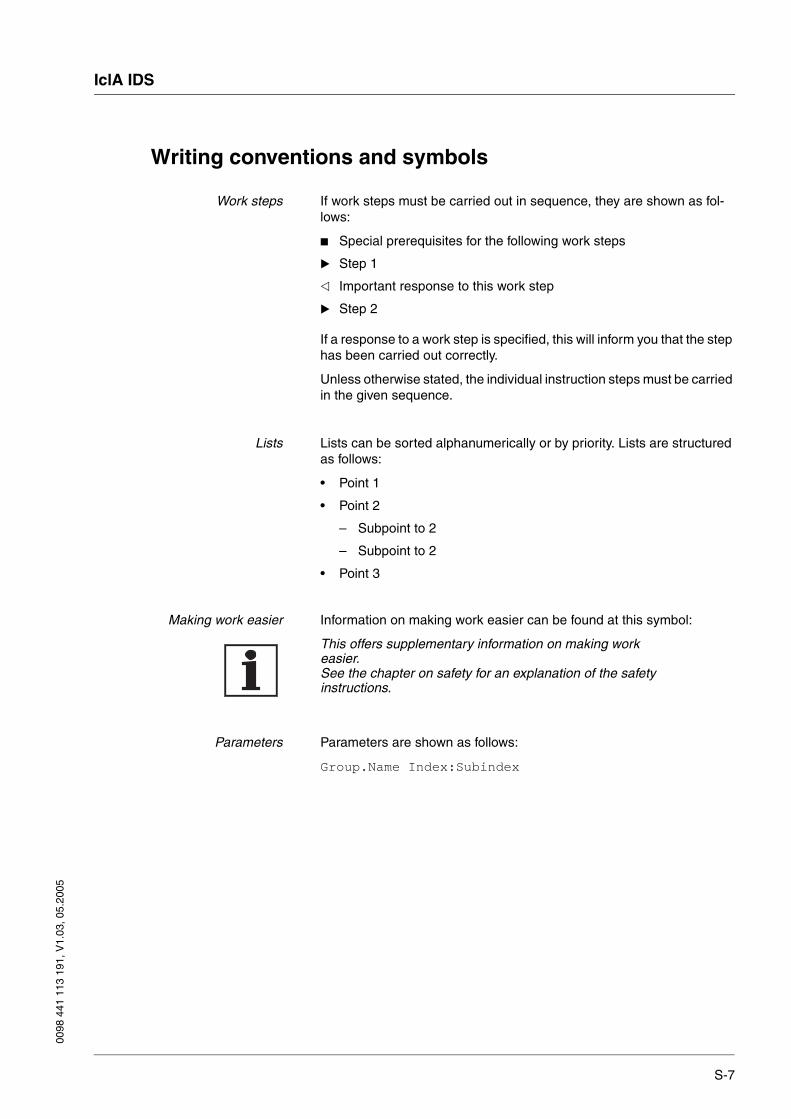

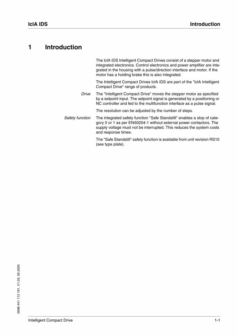
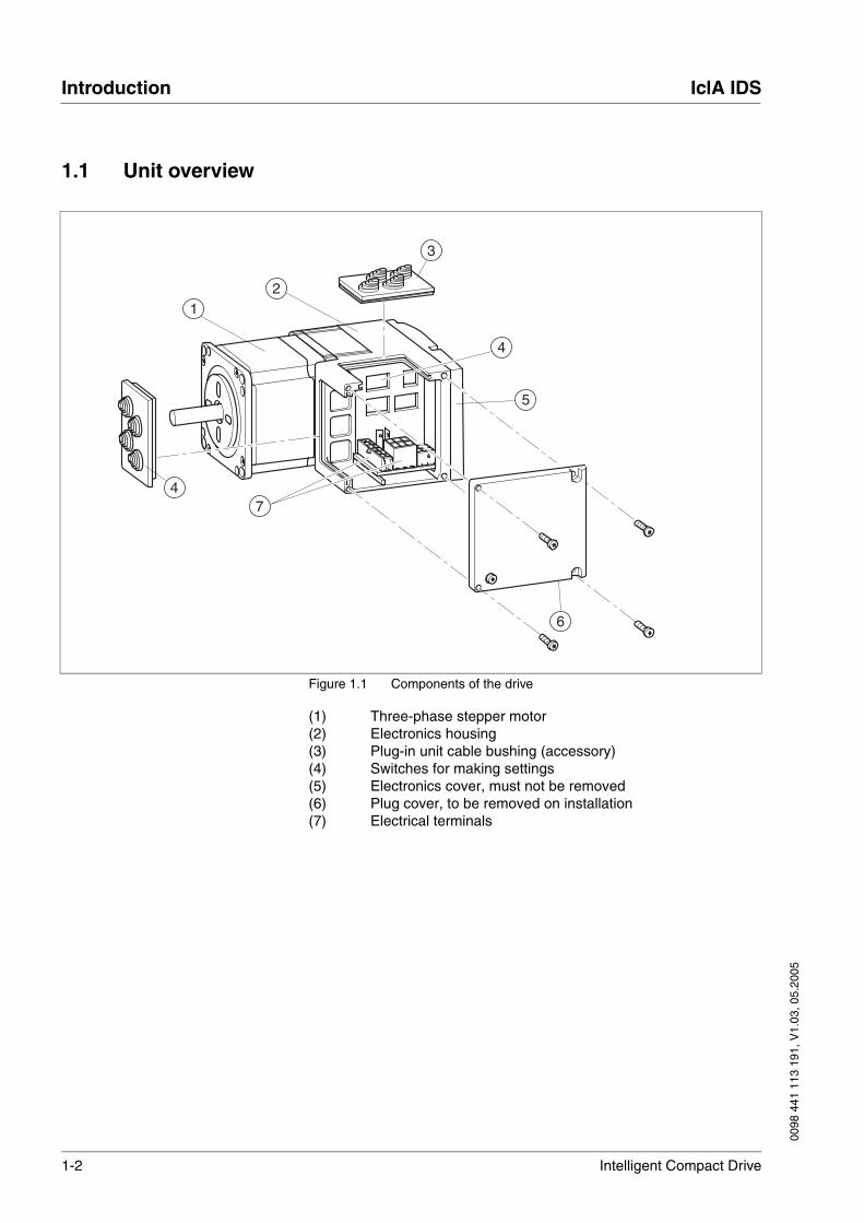
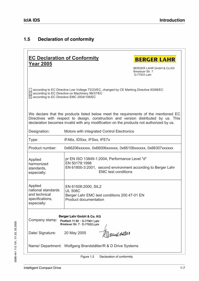

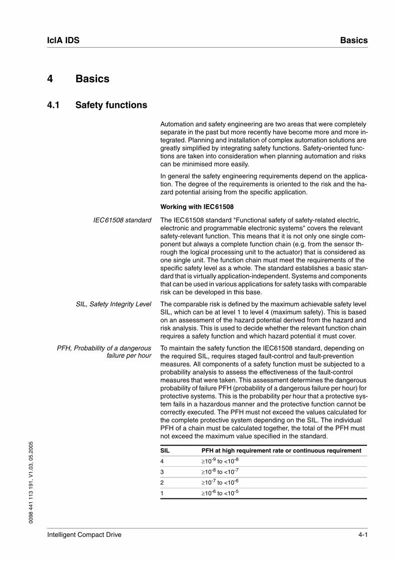


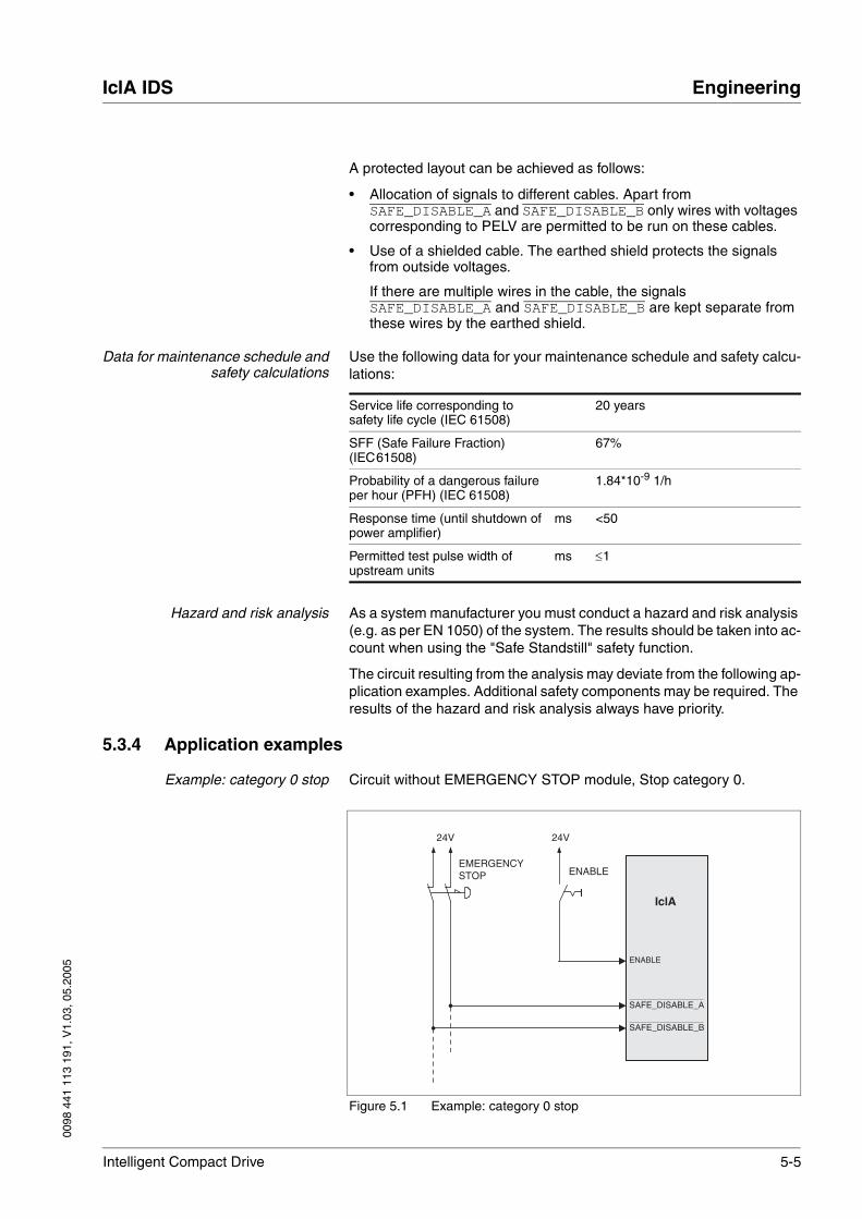
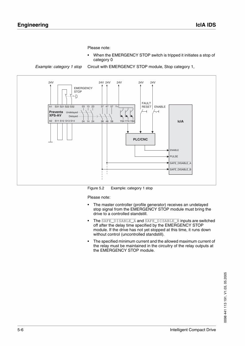

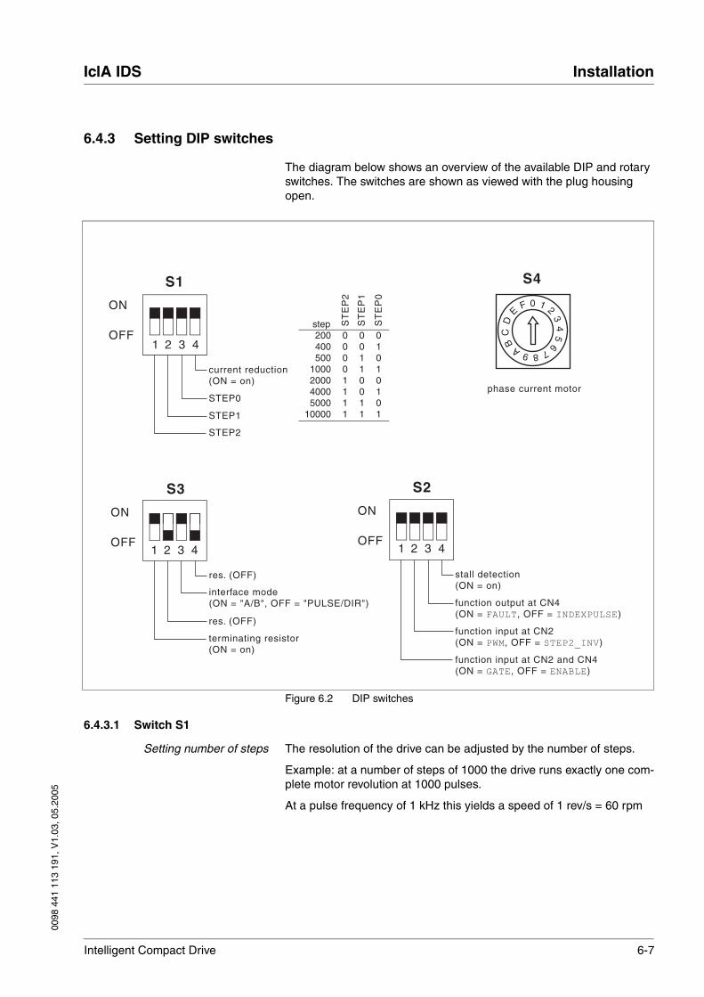
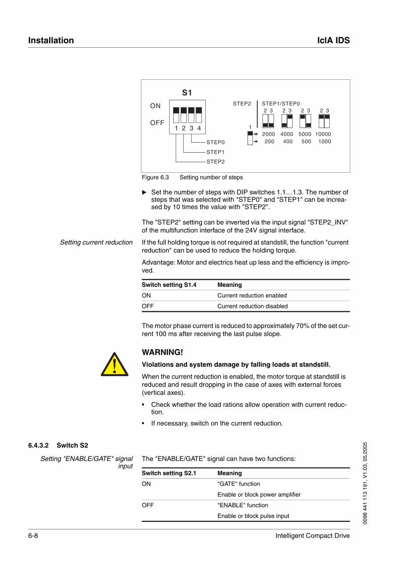
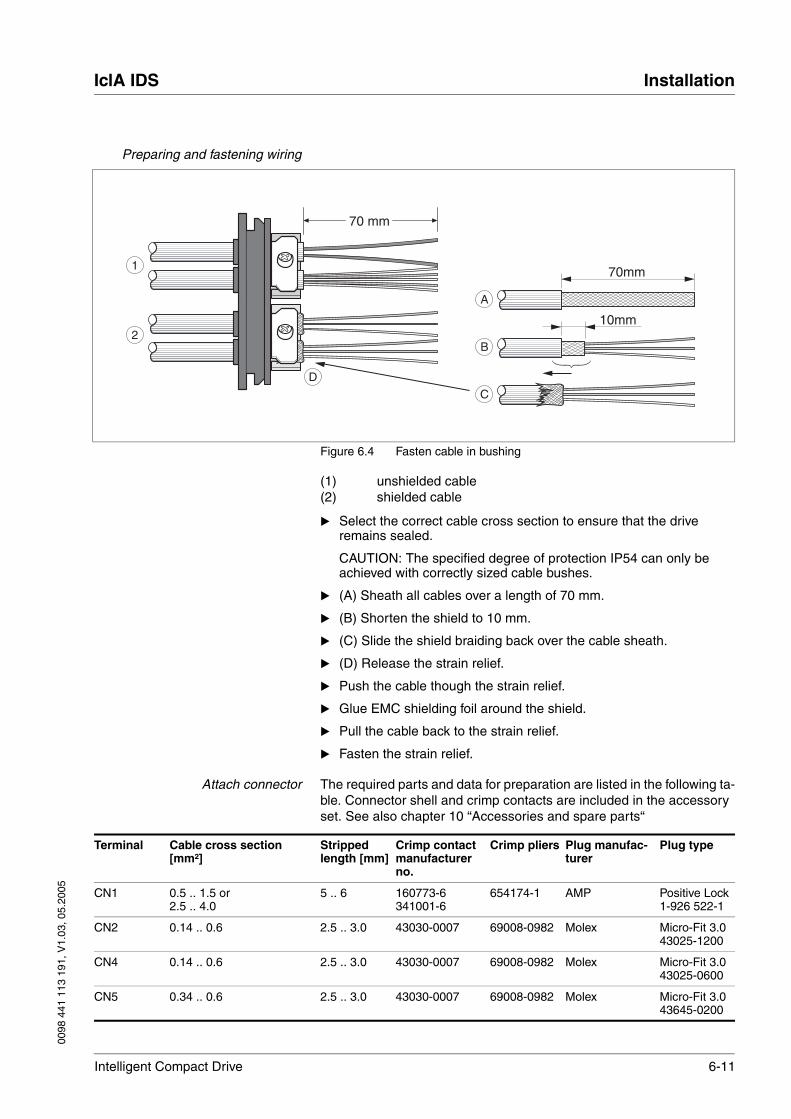


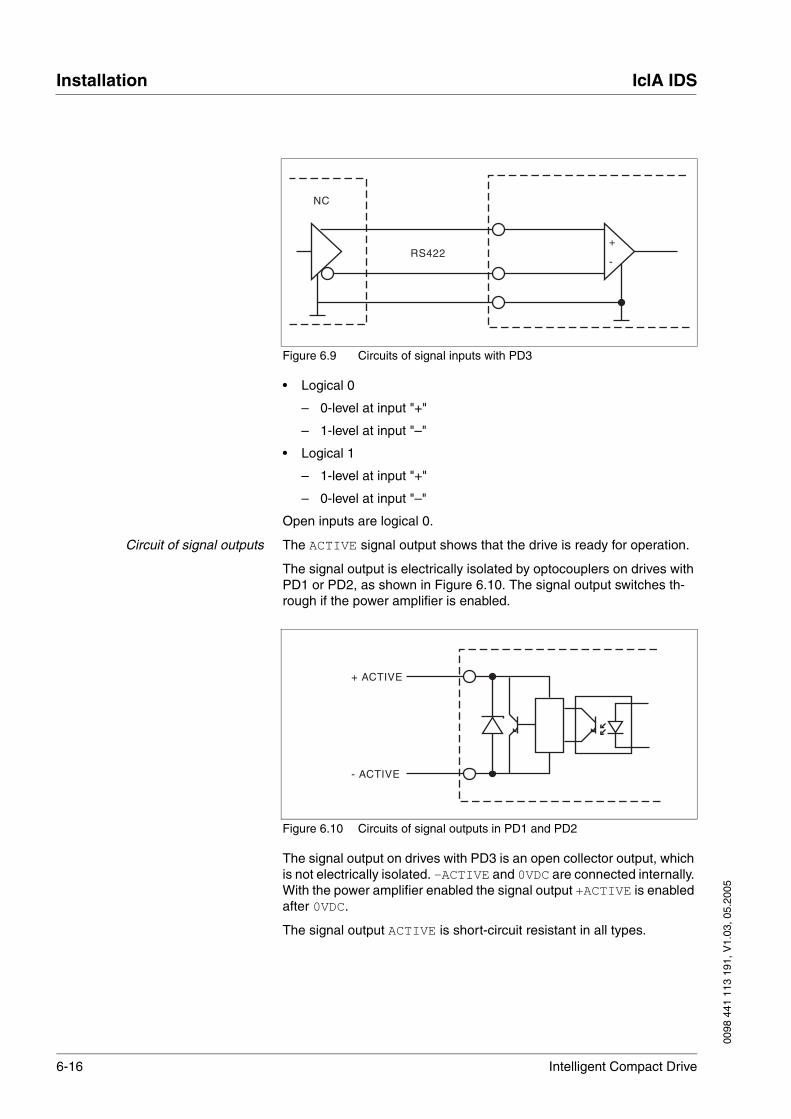
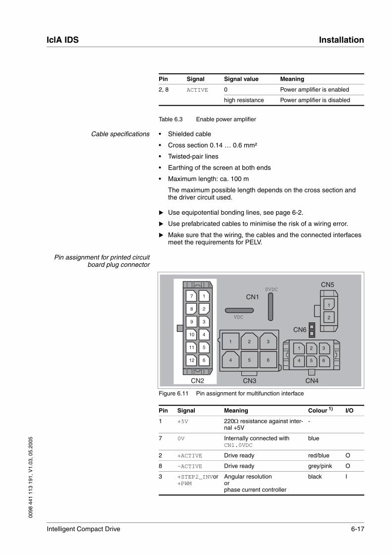

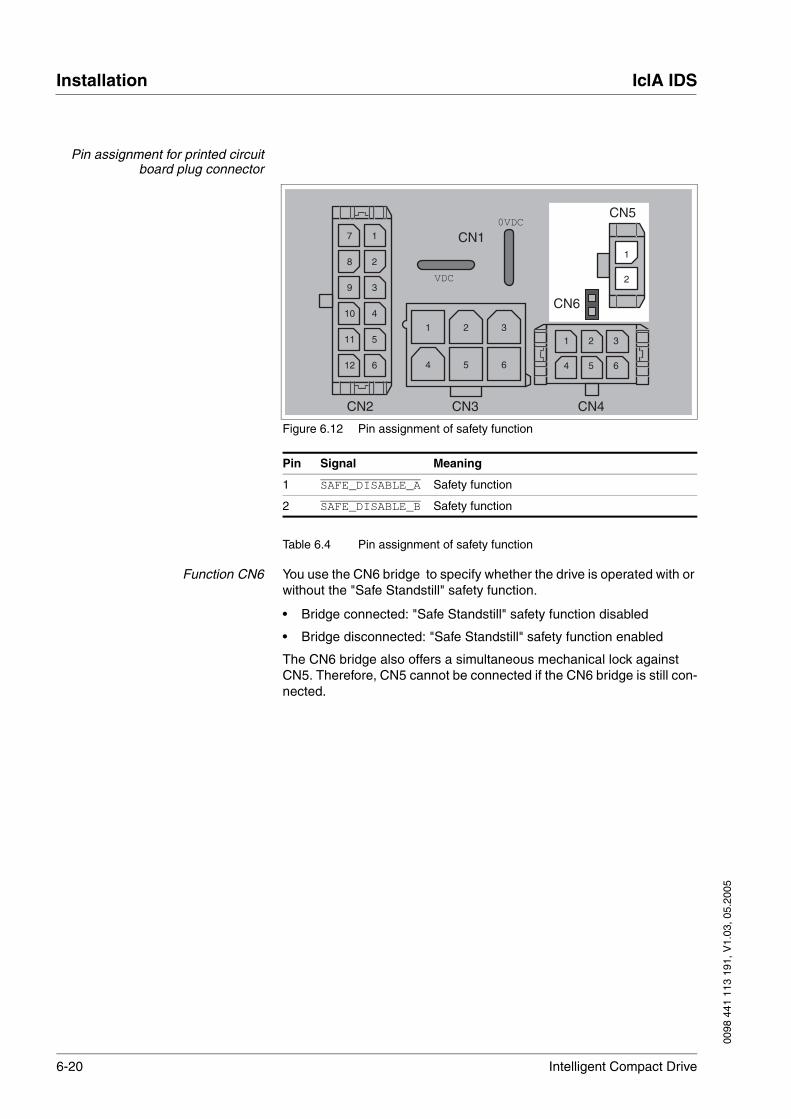


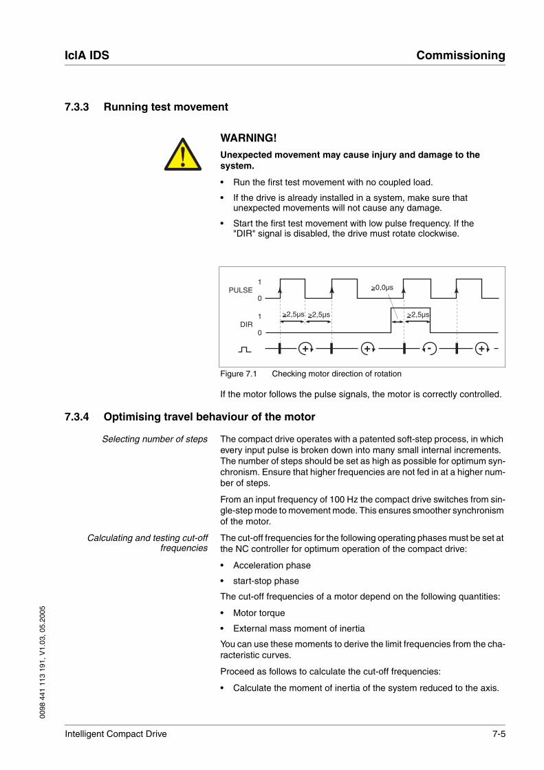
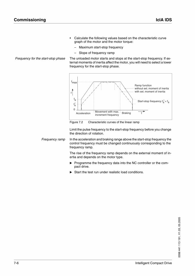
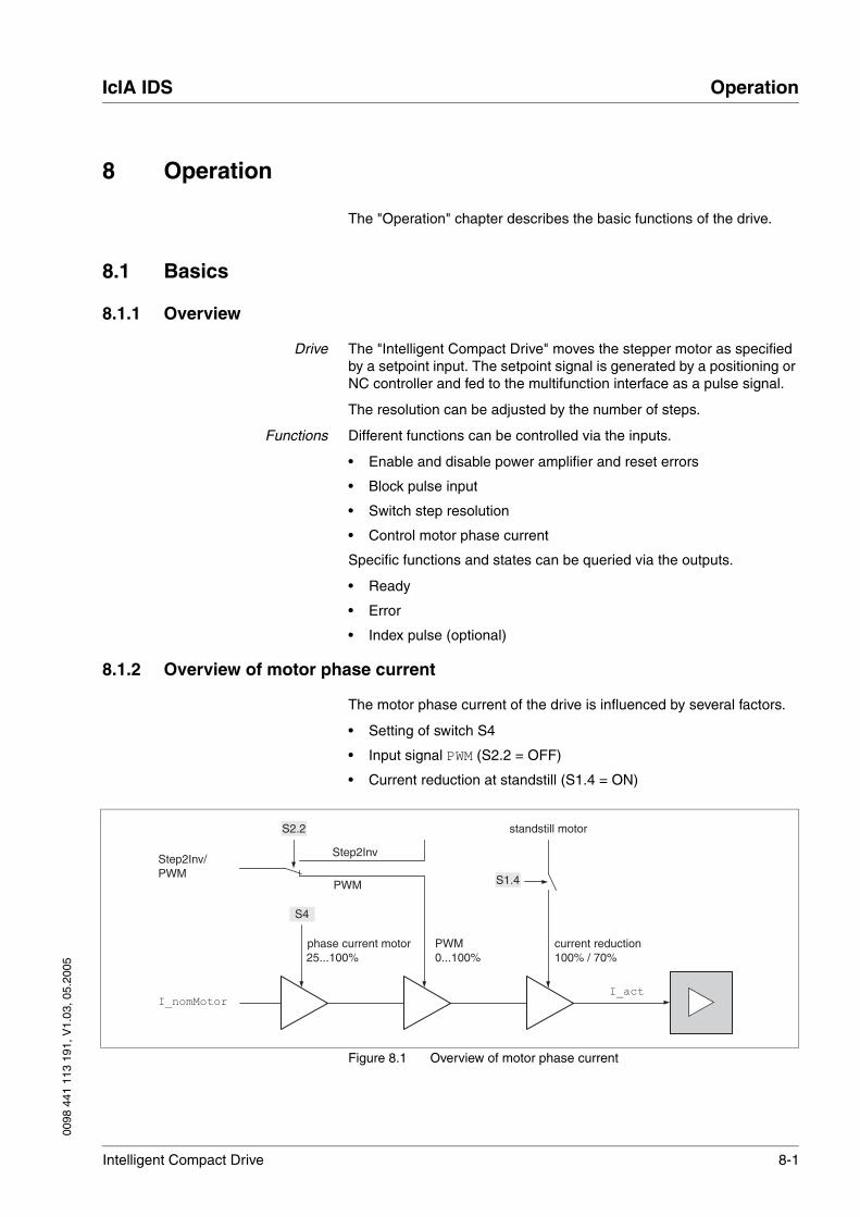
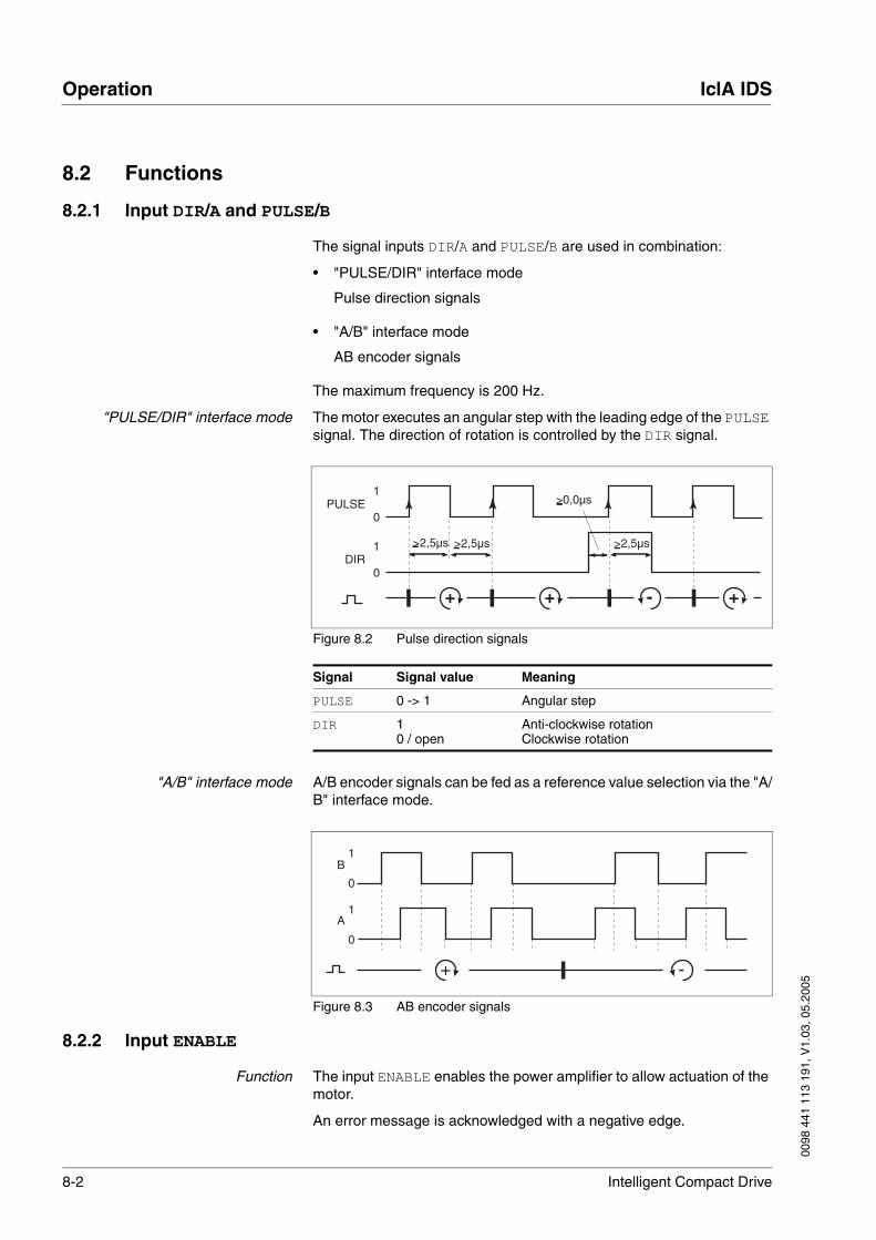
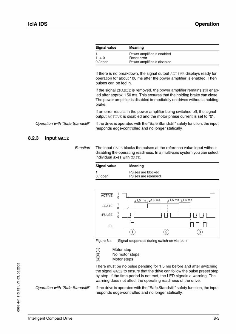
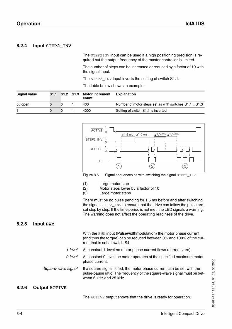

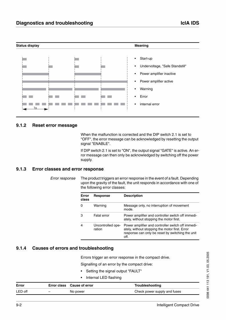

![I N D E X [cms.midcindia.org]cms.midcindia.org/Lists/TenderDocumentsList/Attachments/15854/B-1... · 9 Special Condition 19 19 ... 19 Declaration by Contractor 40 40 ... Undertaking](https://static.documents.pub/doc/80x56/5b083c107f8b9a992a8bfbed/i-n-d-e-x-cms-cms-special-condition-19-19-19-declaration-by-contractor-40.jpg)


![iCLA International Student GuidebookFinal]iCLA International... · 2019. 3. 13. · leatherworking to silk weaving. Kōfu, the capital city of Yamanashi Prefecture and home to the](https://static.documents.pub/doc/80x56/611a876014fd7031b727943f/icla-international-student-guidebook-finalicla-international-2019-3-13.jpg)


