NOTE: When calling to order parts, be sure to have the model number, serial number, voltage,and phase of your machine, along with your customer account number.
GENERAL .................................................................................................................................................. 3
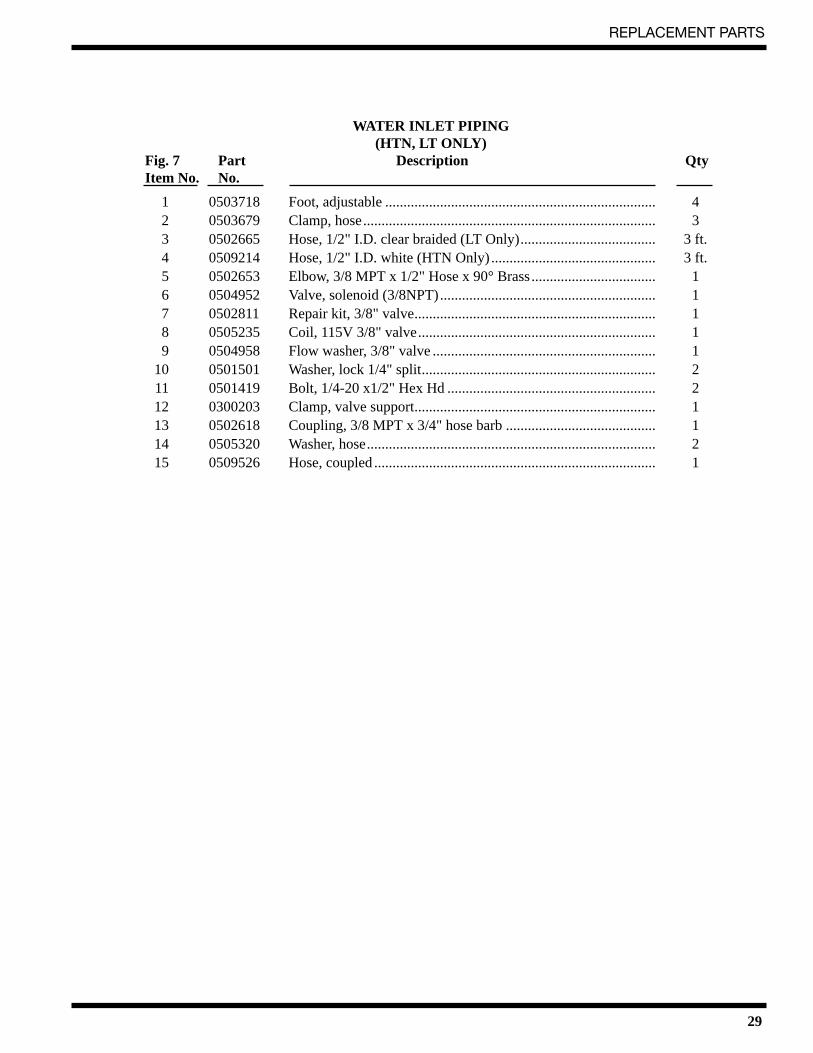
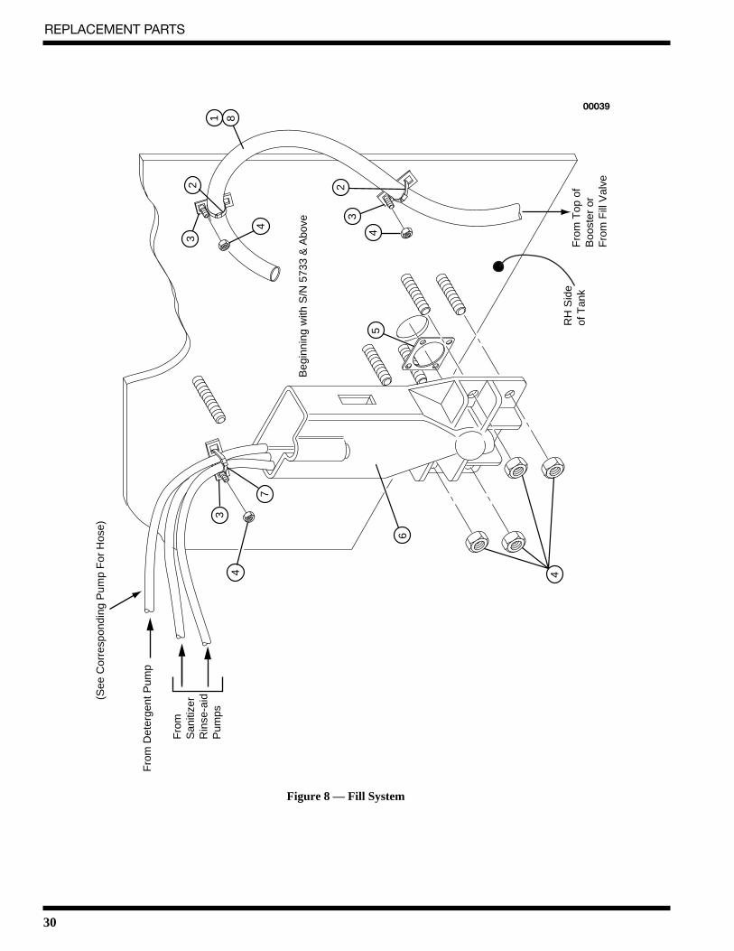
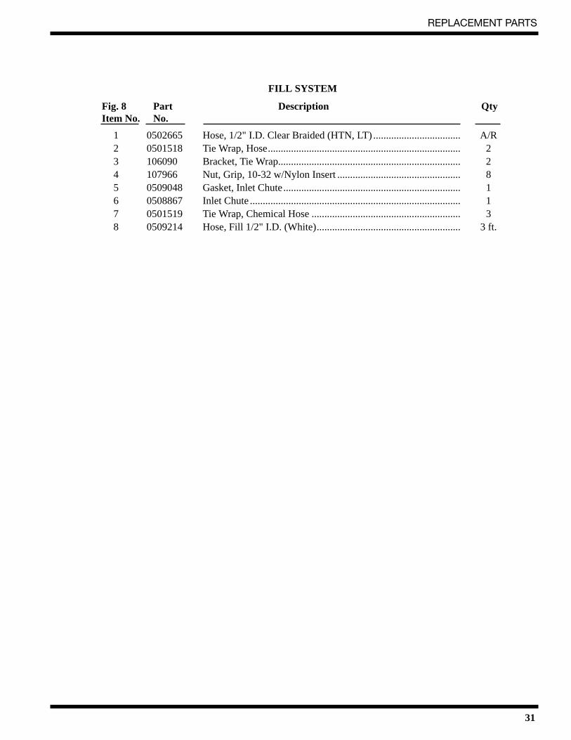
Figure 8—Fill System ................................................................................................................................. 30
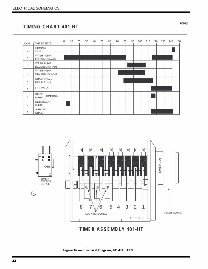
Figure 16—Timer Chart and Diagram, 401-HT, HTN ............................................................................... 44
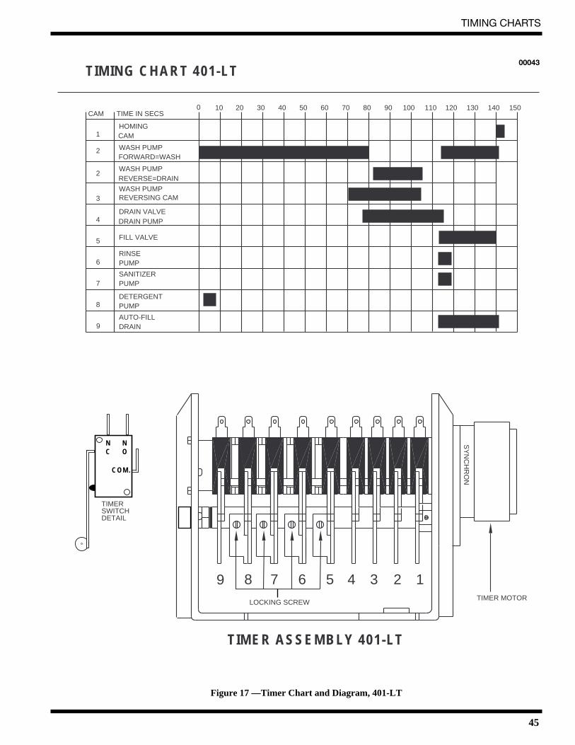
Figure 17—Timer Chart and Diagram, 401-LT .......................................................................................... 45
1
INTRODUCTION
INTRODUCTIONWelcome to Moyer Diebel.
Thank you for choosing Moyer Diebel and for allowing us to take care of your dishwashingneeds.
This manual covers several models. Model numbers are shown on the front cover.
Your machine has been completely assembled, inspected, and thoroughly tested at our factory toeliminate problems at installation before it was shipped to your installation site. This manualprovides:
• Warranty information
• Installation and operation procedures
• Maintenance instructions
• Troubleshooting guide
• Replacement parts lists.
Complete and return your warranty registration card as soon as possible.
Moyer Diebel constantly improves its products; therefore, specifications contained in thismanual may have changed.
For your protection, factory authorized parts should always be used.
Replacement parts may be ordered from your Moyer Diebel authorized parts distributor orservice agency. When ordering parts, supply the model number, serial number, voltage and phaseof your machine, the part number, part description, and quantity.
2
WARRANTY
LIMITED WARRANTYChampion Industries/Moyer Diebel Limited, P.O. Box 4183, Winston-Salem, North Carolina 27115, and P. O. Box 301, 2674North Service Road, Jordan Station, Ontario, Canada L0R 1S0 warrants machines, and parts, as set out below.
Warranty of Machines: Champion Industries/Moyer Diebel Limited warrants all new machines of its manufacture bearingthe name “Champion” or "Moyer Diebel" and installed within the United States and Canada to be free from defects inmaterial and workmanship for a period of one (1) year after the date of installation or fifteen (15) months after the date ofshipment by Champion/Moyer Diebel, whichever occurs first. [See below for special provisions relating to Model Series DFand SW.] The warranty registration card must be returned to Champion/Moyer Diebel within ten (10) days after installation.If warranty card is not returned to Champion/Moyer Diebel within such period, the warranty will expire after one year fromthe date of shipment.
Champion/Moyer Diebel will not assume any responsibility for extra costs for installation in any area where there arejurisdictional problems with local trades or unions.
If a defect in workmanship or material is found to exist within the warranty period, Champion/Moyer Diebel, at its election,will either repair or replace the defective machine or accept return of the machine for full credit; provided, however, as toModel Series DF and SW, Champion/Moyer Diebel's obligation with respect to labor associated with any repairs shall end(a) 120 days after shipment, or (b) 90 days after installation, whichever occurs first. In the event that Champion/MoyerDiebel elects to repair, the labor and work to be performed in connection with the warranty shall be done during regularworking hours by a Champion/Moyer Diebel authorized service technician. Defective parts become the property ofChampion/Moyer Diebel. Use of replacement parts not authorized by Champion/Moyer Diebel will relieve Champion/Moyer Diebel of all further liability in connection with its warranty. In no event will Champion/Moyer Diebel's warrantyobligation exceed Champion/Moyer Diebel's charge for the machine. The following are not covered by Champion/MoyerDiebel's warranty:
a. Lighting of gas pilots or burners.b. Cleaning of gas lines.c. Replacement of fuses or resetting of overload breakers.d. Adjustment of thermostats.e. Adjustment of clutches.f. Opening or closing of utility supply valves or switching of electrical supply current.g. Adjustments to chemical dispensing equipment.h. Cleaning of valves, strainers, screens, nozzles, or spray pipes.i. Performance of regular maintenance and cleaning as outlined in operator’s guide.j. Damages resulting from water conditions, accidents, alterations, improper use, abuse,
tampering, improper installation, or failure to follow maintenance and operation procedures.
Examples of the defects not covered by warranty include, but are not limited to: (1) Damage to the exterior or interior finishas a result of the above, (2) Use with utility service other than that designated on the rating plate, (3) Improper connection toutility service, (4) Inadequate or excessive water pressure, (5) Corrosion from chemicals dispensed in excess of recom-mended concentrations, (6) Failure of electrical components due to connection of chemical dispensing equipment installedby others, (7) Leaks or damage resulting from such leaks caused by the installer, including those at machine table connec-tions or by connection of chemical dispensing equipment installed by others, (8) Failure to comply with local buildingcodes, (9) Damage caused by labor dispute.
Warranty of Parts: Champion/Moyer Diebel warrants all new machine parts produced or authorized by Champion/MoyerDiebel to be free from defects in material and workmanship for a period of 90 days from date of invoice. If any defect inmaterial and workmanship is found to exist within the warranty period Champion/Moyer Diebel will replace the defectivepart without charge.
DISCLAIMER OF WARRANTIES AND LIMITATIONS OF LIABILITY. CHAMPION/MOYER DIEBEL'SWARRANTY IS ONLY TO THE EXTENT REFLECTED ABOVE. CHAMPION/MOYER DIEBEL MAKES NOOTHER WARRANTIES, EXPRESS OR IMPLIED, INCLUDING, BUT NOT LIMITED TO, ANY WARRANTY OFMERCHANTABILITY, OR FITNESS OF PURPOSE. CHAMPION/MOYER DIEBEL SHALL NOT BE LIABLEFOR INCIDENTAL OR CONSEQUENTIAL DAMAGES. THE REMEDIES SET OUT ABOVE ARE THE EXCLU-SIVE REMEDIES FOR ANY DEFECTS FOUND TO EXIST IN CHAMPION/MOYER DIEBEL DISHWASHINGMACHINES AND CHAMPION/MOYER DIEBEL PARTS, AND ALL OTHER REMEDIES ARE EXCLUDED,INCLUDING ANY LIABILITY FOR INCIDENTALS OR CONSEQUENTIAL DAMAGES.
Champion/Moyer Diebel does not authorize any other person, including persons who deal in Champion/Moyer Diebeldishwashing machines, to change this warranty or create any other obligation in connection with Champion/Moyer DiebelDishwashing Machines.
rev. 8699
3
GENERAL
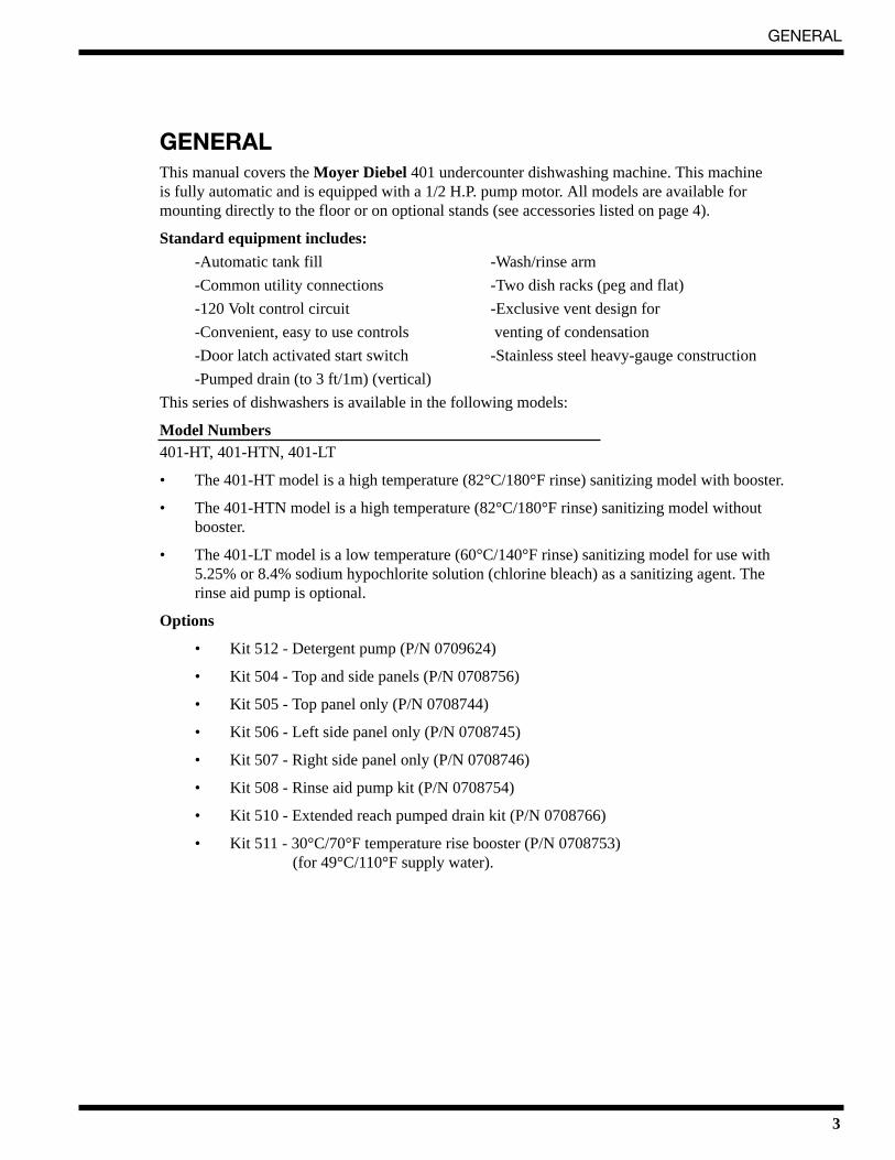
GENERALThis manual covers the Moyer Diebel 401 undercounter dishwashing machine. This machine is fully automatic and is equipped with a 1/2 H.P. pump motor. All models are available formounting directly to the floor or on optional stands (see accessories listed on page 4).
Standard equipment includes:
-Automatic tank fill -Wash/rinse arm
-Common utility connections -Two dish racks (peg and flat)
-120 Volt control circuit -Exclusive vent design for
-Convenient, easy to use controls venting of condensation
-Door latch activated start switch -Stainless steel heavy-gauge construction
-Pumped drain (to 3 ft/1m) (vertical)
This series of dishwashers is available in the following models:
Model Numbers 401-HT, 401-HTN, 401-LT
• The 401-HT model is a high temperature (82°C/180°F rinse) sanitizing model with booster.
• The 401-HTN model is a high temperature (82°C/180°F rinse) sanitizing model withoutbooster.
• The 401-LT model is a low temperature (60°C/140°F rinse) sanitizing model for use with5.25% or 8.4% sodium hypochlorite solution (chlorine bleach) as a sanitizing agent. Therinse aid pump is optional.
• 17RS - 17" rack stand (raises working height and adds rack storage)
• 17T - 17" cabinet (raises working height and adds storage)
• CST - Combination sink/table (scraping and sorting station)
• 101285 - Dish Rack (Peg Rack)
• 101273 - Silverware Rack (Flat Bottom Rack)
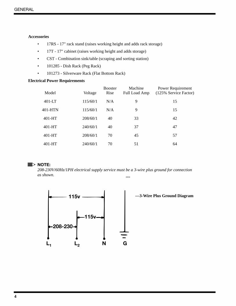
Electrical Power Requirements
Booster Machine Power RequirementModel Voltage Rise Full Load Amp (125% Service Factor)
401-LT 115/60/1 N/A 9 15
401-HTN 115/60/1 N/A 9 15
401-HT 208/60/1 40 33 42
401-HT 240/60/1 40 37 47
401-HT 208/60/1 70 45 57
401-HT 240/60/1 70 51 64
NOTE:208-230V/60Hz/1PH electrical supply service must be a 3-wire plus ground for connection as shown.
—3-Wire Plus Ground Diagram115v
115v
L1 L2 N G
208-230
00036
5
INSTALLATION
INSTALLATIONUnpacking
WARNING: Care should be taken when lifting the machine to prevent damage.
1. Immediately after unpacking your machine, inspect for any shipping damage. If damage isfound, save the packing material and contact the carrier immediately.
2. Remove the dishwasher from the skid. Adjust the feet if required, then move the machine toits permanent location.
3. Level the machine (if required) by placing a level on the top of the machine and adjustingthe feet. Level the machine front-to-back and side-to-side.
CAUTION:After locating your machine, the installation must meet local health codes. An example maybe to seal your machine to the floor using a good grade of silicone sealant.
Electrical ConnectionsWARNING:Electrical and grounding connections must comply with the National Electrical Codeand/or Local Electrical Codes.
WARNING: When working on the dishwasher, disconnect the electric service and tag it to indicate workis being done on that circuit.
1. The electrician should compare the electrical specifications on the machine electrical ratinglabel (located on the lower left front panel) to the electrical power supply before connectingthe machine to the incoming service at a fused disconnect switch.
NOTE: The 208-240V/60Hz/1PH electrical supply service for this machine must be a3-wire plus ground service.
2. On the 208V-240V models, a terminal block is provided on the left front side of themachine (located behind the front panel) for electrical service connections. A fuseddisconnect switch or circuit breaker (supplied by user) is required to protect each powersupply circuit.
3. On 115V models, your machine is already equipped with a 4-foot power cord and plugsuitable for 115V-15A service.
!
!
!
!
INSTALLATION
6
Plumbing ConnectionsCAUTION:Plumbing connections must comply with local sanitary and plumbing codes.
Water Connections
1. Connect the hot water supply (60°C/ 140°F Min) to the 1/2" I.D. fill hose provided. The fillsolenoid valve is equipped with a flow control that will accept water pressures from 172kPa/25 psi to 665 kPa/95 psi.
2. Install a manual shut-off valve with 3/4" garden hose connection in the water supply lineclose to the machine to accommodate installation and servicing the machine. The shut-offvalve should be the same size or larger than the supply line.
3. The fill solenoid valve is equipped with a built-in strainer to protect from particles in thewater supply.
Drain Connections
1. All Models are supplied with a flexible 5/8" I.D. drain hose, which must be connected to a1-1/2" drain using a wye (Y) fitting close to the machine.
Detergent/ChemicalsUse a qualified detergent/chemical supplier for your detergent, rinse aid, and chemicalsanitizer needs.
1. Your machine may be fitted with an optional liquid detergent dispensing pump. Insert thelabeled detergent pickup tube into the detergent container. The pickup tube has a strainer onthe end to prevent crystallized chemical from clogging the supply lines.
2. The cycle timer located in the main control cabinet is equipped with adjustable cams for thechemical dispensing pump(s). The cams control the length of time that the pumps operate.A qualified person may adjust the cam settings if necessary. Refer to the timer chartdiagram(s) at the end of the manual for timer cam locations. Factory time settings are onlyapproximate. Have your chemical supplier check the concentration and make the necessaryadjustments.
NOTE: A nonchlorinated detergent is recommended for your dishwasher.
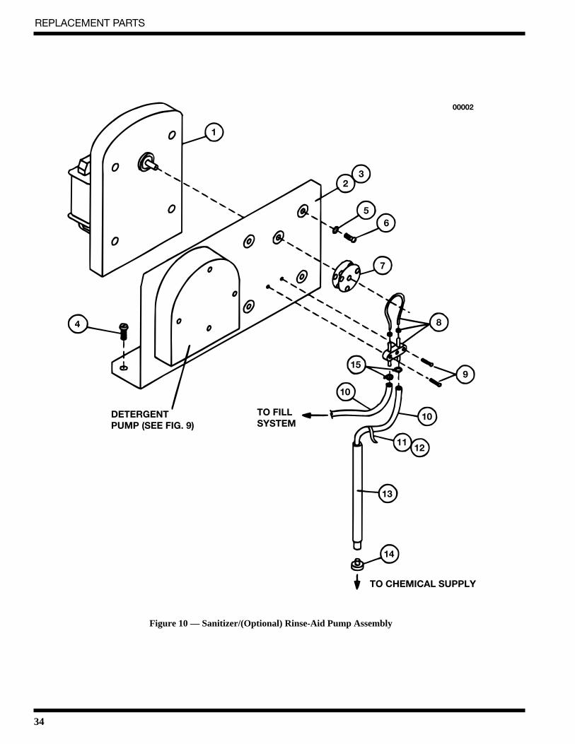
Rinse Aid1. An optional rinse aid pump may be added for all models. Insert the labeled Rinse Aid
pickup tube into the rinse aid container. Contact your chemical supplier for adjustment toensure proper dosage.
Chemical Sanitizer1. Model 401-LT is supplied with chemical sanitizer dispensing pump. Using a 5.25% or 8.4%
sodium hypochlorite solution, insert the labeled Chemical Sanitizer pickup tube into thechemical sanitizer container. Have your chemical supplier set chemical dosage according tolocal code.
2. Contact your chemical supplier for adjustment of the chemical sanitizer to ensure properdosage.
!
INSTALLATION
7
Completing Installation1. Remove any foreign material from inside the machine.
2. Center the scrap screen over the sump opening.
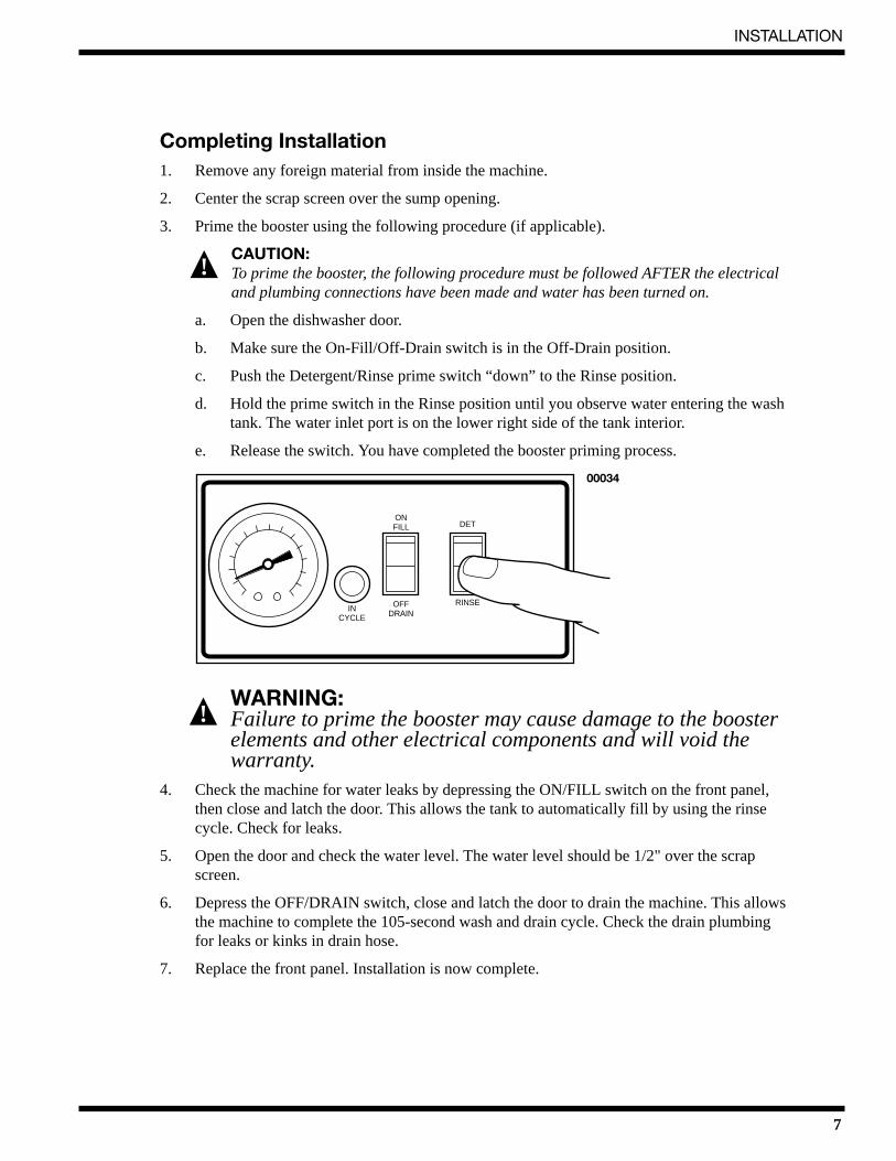
3. Prime the booster using the following procedure (if applicable).
CAUTION: To prime the booster, the following procedure must be followed AFTER the electrical and plumbing connections have been made and water has been turned on.
a. Open the dishwasher door.
b. Make sure the On-Fill/Off-Drain switch is in the Off-Drain position.
c. Push the Detergent/Rinse prime switch “down” to the Rinse position.
d. Hold the prime switch in the Rinse position until you observe water entering the washtank. The water inlet port is on the lower right side of the tank interior.
e. Release the switch. You have completed the booster priming process.
WARNING: Failure to prime the booster may cause damage to the booster elements and other electrical components and will void the warranty.
4. Check the machine for water leaks by depressing the ON/FILL switch on the front panel,then close and latch the door. This allows the tank to automatically fill by using the rinsecycle. Check for leaks.
5. Open the door and check the water level. The water level should be 1/2" over the scrapscreen.
6. Depress the OFF/DRAIN switch, close and latch the door to drain the machine. This allowsthe machine to complete the 105-second wash and drain cycle. Check the drain plumbingfor leaks or kinks in drain hose.
7. Replace the front panel. Installation is now complete.
!
!
INCYCLE
OFFDRAIN
ONFILL DET
RINSE
00034
8
OPERATION
OPERATIONOperation Summary (See Timer Chart in back of manual)The following is a summary of your Undercounter Dishwashing Machine operating cycle:
1. The cycle begins when you close and latch the door.
2. The green cycle lamp lights and the wash pump starts.
3. The pump runs during the wash cycle for approximately 80 seconds.
4. The wash pump stops, and the drain valve is opened.
5. After a 2-3 second pause, the pump drain cycle begins and continues for approximately 30seconds.
6. After a 2-3 second pause, the fill valve opens, and the pump starts for the rinse cycle.
7. Within approximately 25 seconds, the rinse cycle is complete. The pump stops, the greencycle lamp turns off, and the cycle is complete.
8. Open the door and remove the rack of clean ware. The door must remain open for 5seconds to allow the timer to reset before starting another cycle.
Daily Operation ProceduresThe operation of your dishwasher will be more efficient when these procedures are followed:
1. Check that the spray arm and scrap screen are in place.
2. Close and latch the door. Push the ON/FILL switch to the ON position. The tank will beginfilling with water. This procedure is followed only when the tank is empty.
3. When the tank is full, check the wash tank temperature gauge. Minimum wash temperaturesare:
• 401-HT, 401-HTN - 66°C/150°F.
• 401-LT - 60°C/140°F.
CAUTION:If the wash water temperature falls below the minimums listedabove, you must run an empty cycle to refill with fresh hot water.
4. Scrap and preflush all items to be washed, and load the items into the rack. DO NOTOVERLOAD the rack. Wash only one layer of silverware in a rack.
5. Open the door and insert the rack into the machine.
6. Close and latch the door. This will start the wash cycle. The green cycle lamp located on thefront control panel will light. This lamp will remain on until the entire wash and rinse cycleare completed.
!
9
OPERATION
NOTE: The machine may be stopped at any time by opening the door. When restarted, the cycle does not start over. It will continue from the point at which it was interrupted.
7. Check the rinse temperature during the final rinse (120 seconds into cycle). The rinsetemperature must be 82°C/180°F minimum for models 401-HT and 401-HTN and60°C/140°F for model 401-LT.
8. The pump will automatically stop and the green cycle light will turn off indicating the cycleis completed.
9. Open the door and remove the rack.
10. Repeat steps 4-9 for additional cycles. Machine operation is automatic.
11. CLEAN the scrap screen after every meal period. During heavy usage, the scrap screenshould be cleaned more frequently.
CAUTION: Poor machine performance and/or damage to the machine can occur if the scrap screen becomes clogged with soil or waste particles.
12. To drain water out of the tank at the end of each day. Flip OFF/DRAIN switch to DRAINposition. Close and latch door. Machine will drain completely in approximately 105seconds.
CAUTION: DO NOT LEAVE WATER IN THE TANK OVERNIGHT. Water left in the tank overnight will allow harmful chemicals to deteriorate the tank.
!
!
10
MAINTENANCE
MAINTENANCEThe efficiency and life of your machine is increased by regularly scheduled preventivemaintenance. A well maintained machine gives better results and service. An investment of a fewminutes of daily maintenance will be worthwhile.
The best maintenance you can provide is to keep your machine clean. Components that are notregularly cleaned and flushed will clog and become inoperative.
Intervals shown in the following schedules represent an average length of time betweennecessary maintenance. Maintenance intervals should be shortened whenever your machine isfaced with abnormal working conditions, hard water, or multiple shift operations.
Cleaning Schedule• Daily-Every 8 Hours
1. Depress the OFF/DRAIN switch to OFF and close and latch the door to drain thetank.
2. Open the door and remove the lower spray arm by unscrewing the knurled fastener.
3. Remove the scrap screen carefully to keep soil or waste particles from falling into the sump. Remove any material caught in pump intake.
4. Clean inside the tank with clean water. Backflush the scrap screen until it is clean. Do not strike the screen against solid objects.
5. Clean the wash arm to remove any debris from spray openings. Do not strike the sprayarm against solid objects.
6. Reinstall the scrap screen and spray arm.
7. Leave the door open overnight to allow drying.
8. Report any unusual conditions to your supervisor.
• Meal Periods
1. Clean the scrap screen after every meal period and more frequently during heavyusage. Do not allow the scrap screen to become clogged with soil or waste particles.
11
MAINTENANCE
DelimingYour dishwasher should be delimed regularly as required. This will depend on the mineralcontent of your water.
Inspect your machine interior for lime deposits. If deliming is required, a deliming agent shouldbe used for best results.
If you have the chemical sanitizing model (401-LT), carefully follow the following procedurebefore deliming:
DANGER: Deliming solution or other acids must not come in contact with household bleach (sodiumhypochlorite) or any chemicals containing chlorine, iodine, bromine, or fluorine. Mixingwill cause hazardous gases to form. Skin contact with deliming solutions can cause severeirritation and possible chemical burns. Consult your chemical supplier for specific safetyprecautions.
1. Remove the sanitizer tube from the container. Place the tube into a container of hot water.
2. Depress and hold the SANITIZER prime switch (located on the front panel) until allsanitizer has been purged from the hoses.
3. Close the door and depress the door latch. Complete two operating cycles to purge themachine of all sanitizer.
Deliming ProcedureComplete the following procedure to delime your machine:
1. Add the delime chemical to wash the tank (per chemical supplier specifications).
2. Close and latch the door.
3. The dishwasher will complete a regular cycle.
4. Check the deliming results and repeat if necessary per the chemical supplier’sspecifications.
5. Operate the dishwasher for at least four complete cycles to purge the machine of anydeliming chemicals.
6. For chemical sanitizing Model 401-LT, re-prime sanitizer chemical line and run anadditional cycle to flush any excess sanitizer from machine.
7. Drain the dishwasher. Deliming is complete.
!
12
MAINTENANCE
Maintenance Schedule• As Required
1. Check the temperature gauge reading.
2. Check the chemical supplies and refill as necessary.
• Weekly
1. Inspect all water lines for leaks and tighten them at joints if required.
2. Clean all detergent residue from the exterior of the machine.
3. Check the drain for leaks.
4. Remove and closely inspect the spray arm for blockage.
5. Check for damage to the scrap screen. Ineffective screening can cause wash system failures, or poor washing results.
6. Clean the detergent, sanitizer, and rinse aid supply tubes (if equipped). Complete thefollowing procedure:
a. Remove the detergent, sanitizer, and rinse aid pick-up tube(s) from the container(s). Place the tube(s) into a container of hot water.
b. Ensure ON/OFF switch is in the ON position depress and hold the DET primeswitch (located on the front panel) until clear water enters the tank through thefill air gap (located on the right side of the tank).
c. If your machine is equipped with a sanitizer and/or rinse aid pump, follow thesame procedure by pressing the SANITIZER and/or the RINSE AID primeswitch until clear water enters the tank through the fill air gap.
d. When completed, remove the pickup tubes from the hot water and reinsert theminto the correct chemical containers. Repeat the priming procedures to ensurethat chemicals have filled the tubes for the next operating period.
e. Run a complete cycle to flush chemicals from the tank.
13
TROUBLESHOOTING
TROUBLESHOOTINGBefore determining any specific cause of a breakdown or abnormal operation of your dishwasher,check that:
1. Power supply is turned on. All switches are ON.
2. Wash arm is clean.
3. Scrap screen is properly positioned and clean.
4. Thermostat is at the correct setting.
5. Sanitizer, detergent, and rinse additive dispensers (if equipped) are adequately filled.
6. All plumbing valves are open and drain hose is not kinked.
If a problem still exists, use the following table for troubleshooting.
CONDITION CAUSE SOLUTIONMachine will not start Door not closed and latched . . . . . . . . Make sure door is fully latched
Main switch off, or unit unplugged . . Check disconnect or plug into outlet
Low or no water Main water supply is turned off . . . . Turn on house water supplyWater level setting low. . . . . . . . . . . . Adjust water level
Chemical not feeding No chemical in container . . . . . . . . . . Replace or fill containerFeed tubes to/from chemical . . . . . . . Clear obstruction and flushpump clogged with hot waterScreen on feed tube clogged. . . . . . . . Clean and replaceTubing kinked or split . . . . . . . . . . . . Straighten or replace tubing
Water temperature Incoming water temperature. . . . . . . . Raise house supply temperature tois low when in use at machine too low 60°C/140°F for all machines
Insufficient pumped spray Clogged spray arm . . . . . . . . . . . . . . . Cleanpressure Scrap screen full . . . . . . . . . . . . . . . . . Must be kept clean and in place
Low final rinse temperature Low incoming water. . . . . . . . . . . . . . Check the booster - be sure thetemperature thermostat is set to maintain 66°C/180°F
temperature (401-LT is 60°C/140°F)(Check all valves to besure they are clean and operating)
Detergent setting too low . . . . . . . . . Contact detergent supplierWash water temperature too low . . . . See above booster temperatures, run cycleWash arm clogged . . . . . . . . . . . . . . . Clean wash armImproperly scraped dishes . . . . . . . . . Check scraping proceduresWare being improperly. . . . . . . . . . . . Use proper racks - do not overloadplaced in rack racksImproperly cleaned . . . . . . . . . . . . . . Unclog wash arm to maintainequipment proper pressure and flow conditions
No water in wash well Opening door prior . . . . . . . . . . . . . . . Close and latch door. Wait for green lightto cycle completion to go out before opening door.Water supply is turned off . . . . . . . . . Turn on supply
No water in wash tank Door not latched . . . . . . . . . . . . . . . . . Latch doorafter activating the Wait for wash tank to fillON/FILL switch
THIS PAGEINTENTIONALLY
LEFT BLANK
15
REPLACEMENT PARTS
REPLACEMENTPARTS
16
REPLACEMENT PARTS
12
12
12
11
10
00050
96
54
3
7
2
1
8
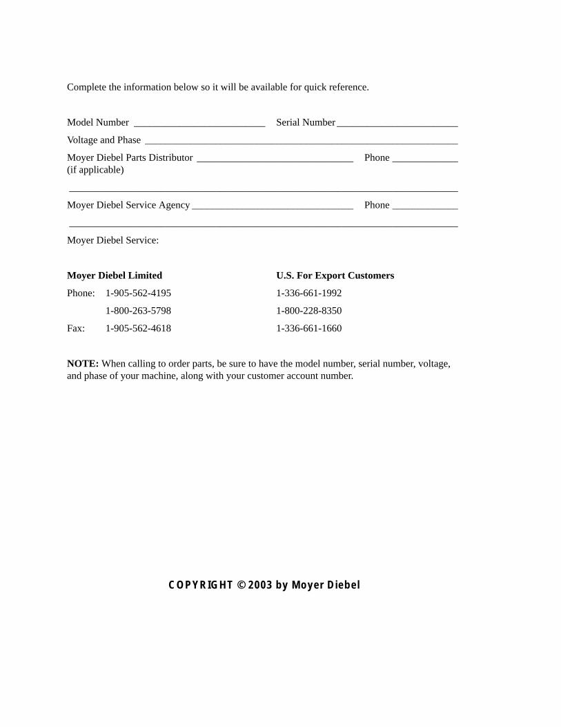
Figure 1 — Track and Panel Assembly
17
REPLACEMENT PARTS
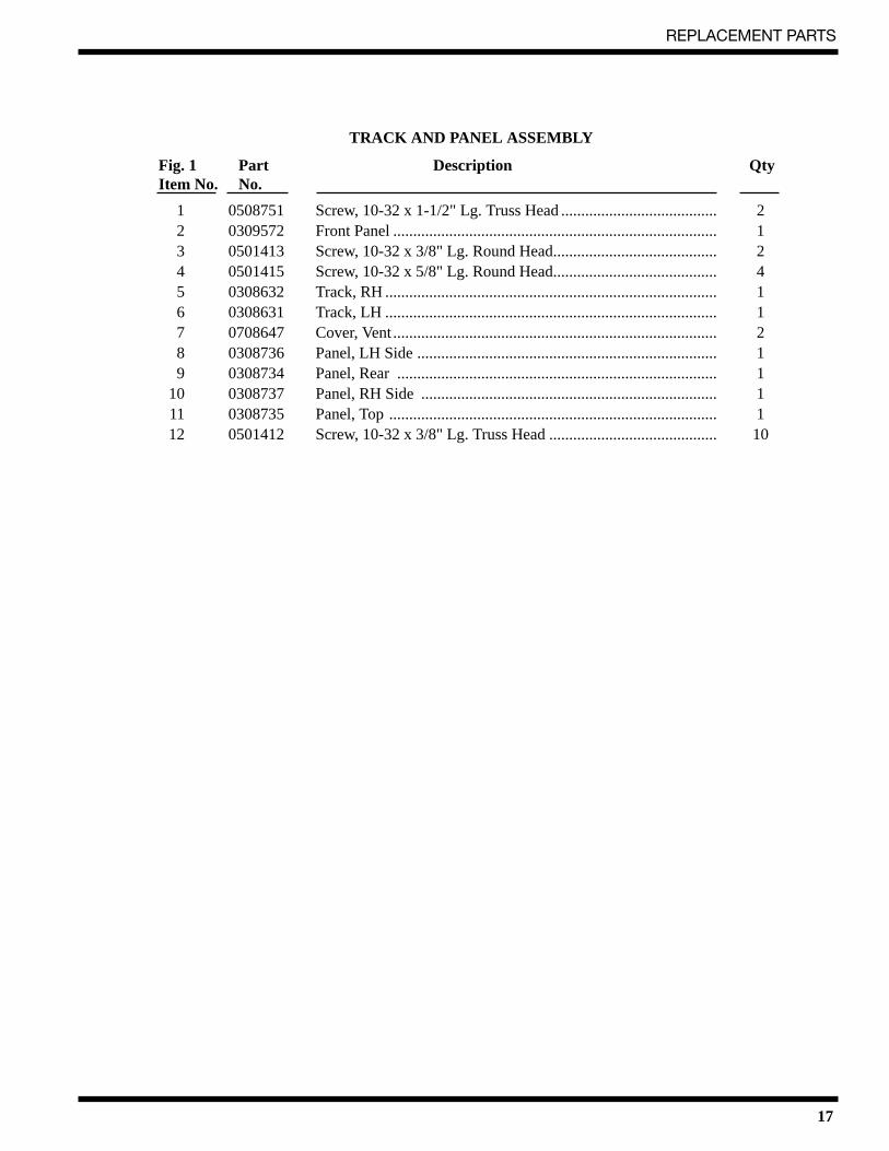
TRACK AND PANEL ASSEMBLY
Fig. 1 Part Description QtyItem No. No.
1 0508751 Screw, 10-32 x 1-1/2" Lg. Truss Head ....................................... 22 0309572 Front Panel ................................................................................. 13 0501413 Screw, 10-32 x 3/8" Lg. Round Head......................................... 24 0501415 Screw, 10-32 x 5/8" Lg. Round Head......................................... 45 0308632 Track, RH ................................................................................... 16 0308631 Track, LH ................................................................................... 17 0708647 Cover, Vent ................................................................................. 28 0308736 Panel, LH Side ........................................................................... 19 0308734 Panel, Rear ................................................................................ 1
10 0308737 Panel, RH Side .......................................................................... 111 0308735 Panel, Top .................................................................................. 112 0501412 Screw, 10-32 x 3/8" Lg. Truss Head .......................................... 10
18
REPLACEMENT PARTS
1
2
3
57 8
9
10
11
12
13 14
15
1617
18
15
1
6
4
1
00020
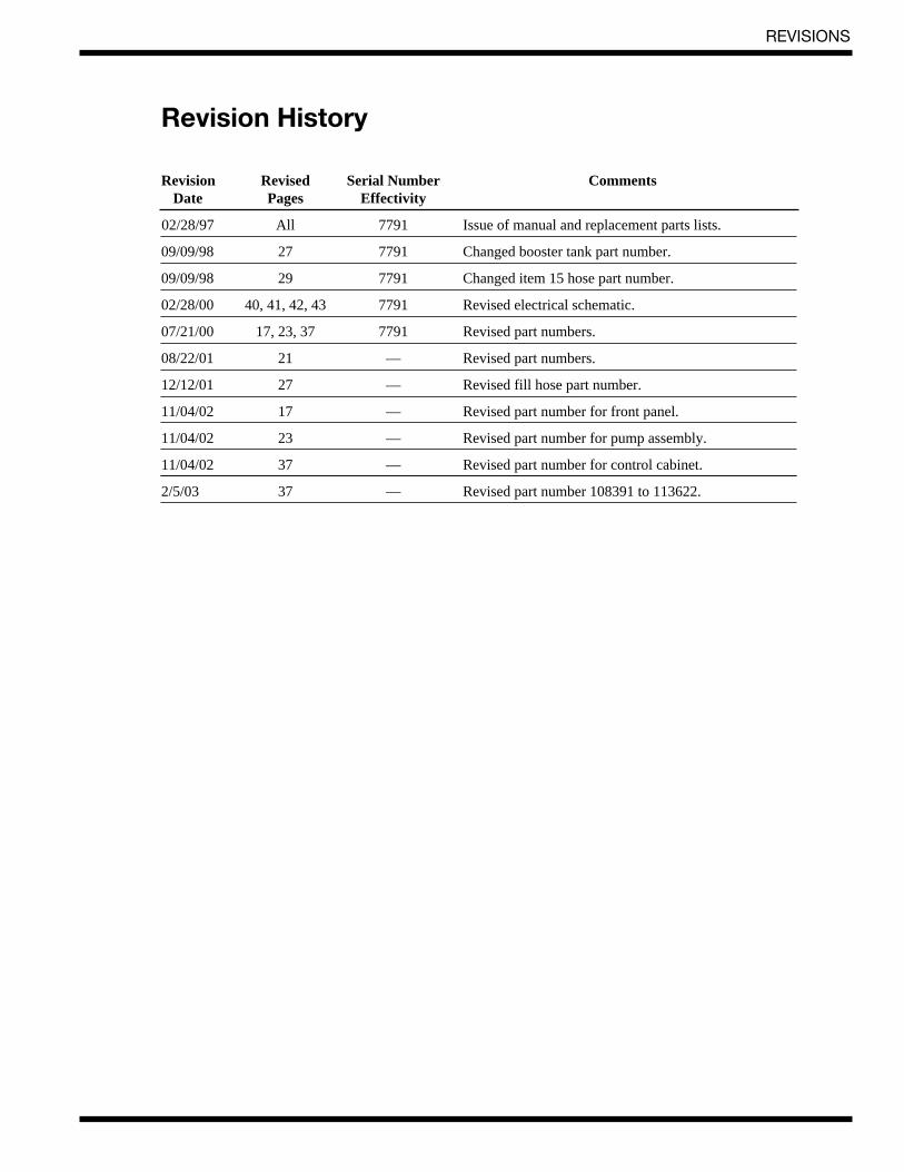
Figure 2 — Door and Switch Assembly
19
REPLACEMENT PARTS
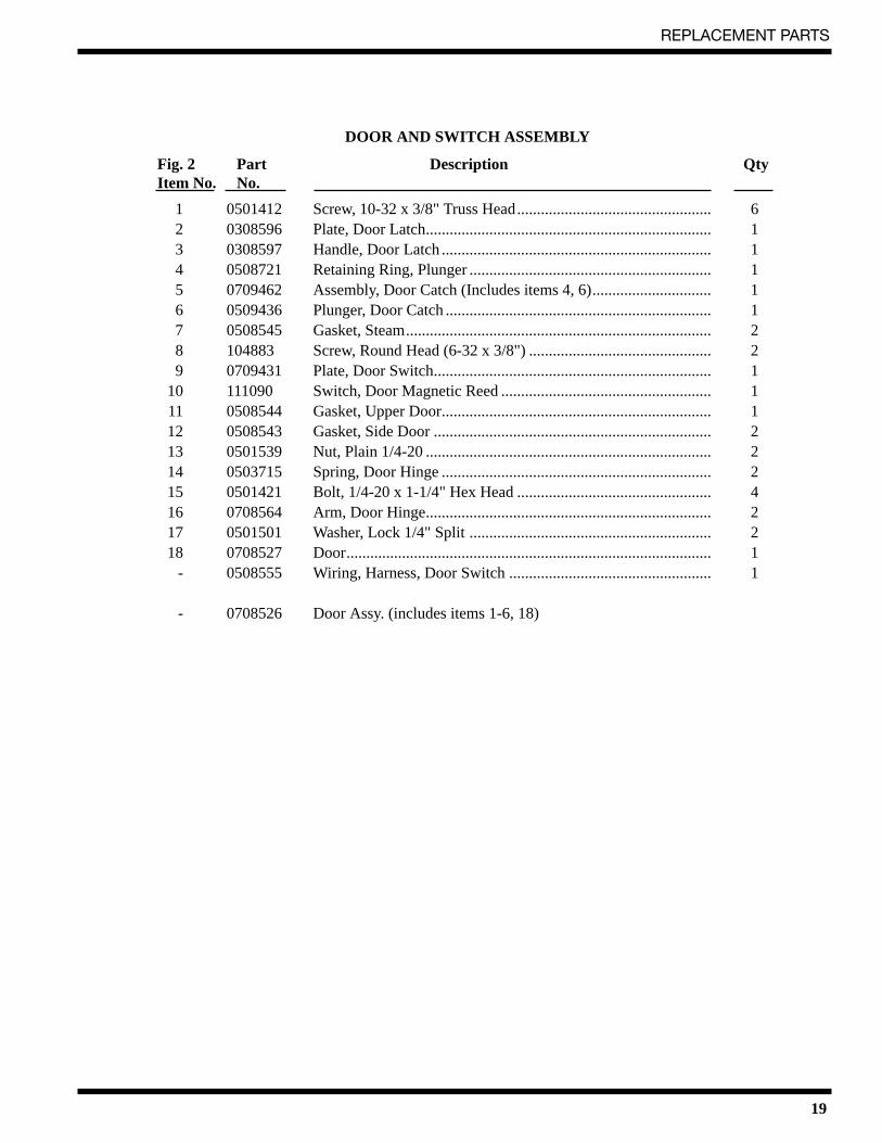
DOOR AND SWITCH ASSEMBLY
Fig. 2 Part Description QtyItem No. No.
1 0501412 Screw, 10-32 x 3/8" Truss Head................................................. 62 0308596 Plate, Door Latch........................................................................ 13 0308597 Handle, Door Latch .................................................................... 14 0508721 Retaining Ring, Plunger ............................................................. 15 0709462 Assembly, Door Catch (Includes items 4, 6).............................. 16 0509436 Plunger, Door Catch ................................................................... 17 0508545 Gasket, Steam............................................................................. 28 104883 Screw, Round Head (6-32 x 3/8") .............................................. 29 0709431 Plate, Door Switch...................................................................... 1
10 111090 Switch, Door Magnetic Reed ..................................................... 111 0508544 Gasket, Upper Door.................................................................... 112 0508543 Gasket, Side Door ...................................................................... 213 0501539 Nut, Plain 1/4-20 ........................................................................ 214 0503715 Spring, Door Hinge .................................................................... 215 0501421 Bolt, 1/4-20 x 1-1/4" Hex Head ................................................. 416 0708564 Arm, Door Hinge........................................................................ 217 0501501 Washer, Lock 1/4" Split ............................................................. 218 0708527 Door............................................................................................ 1
- 0508555 Wiring, Harness, Door Switch ................................................... 1
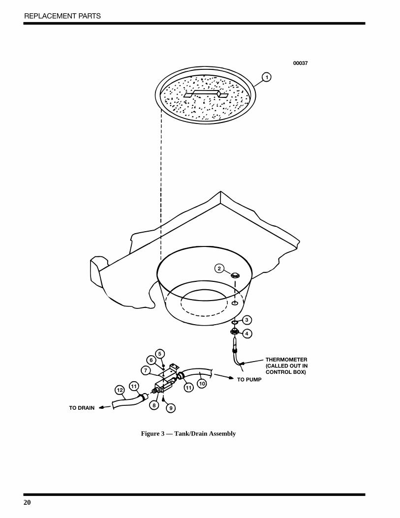
10 0507265 Hose, 5/8" ID x 7/8" OD PVC Braided (3 ft.) .............................. 211 0510082 Clamp, hose................................................................................ 212 0509302 Hose 5/8" ID x 1" OD Braided PVC.......................................... 1
22
REPLACEMENT PARTS
TANKBOTTOM
12
14
1311
10
9
8
7
6
5
4
2 3
1
00005
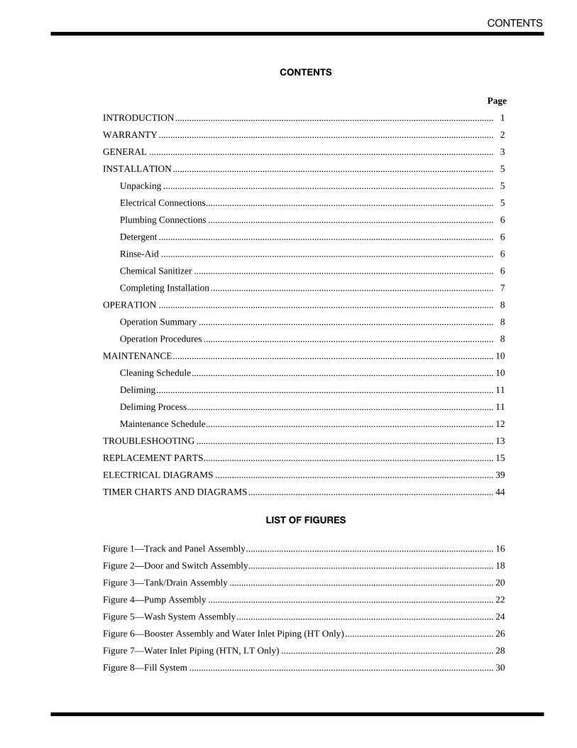
Figure 4 — Pump Assembly
23
REPLACEMENT PARTS
PUMP ASSEMBLY
Fig. 4 Part Description QtyItem No. No.
1 0508542 Spindle, Lower Wash Arm ......................................................... 12 0501431 Screw, 8-32 x 1-1/8" Round Head.............................................. 43 0501425 Screw, 8-32 x 5/8" Round Head ................................................. 44 0502742 Housing, Top (No Hole)............................................................. 15 0502741 Diffuser....................................................................................... 16 0502704 Impeller ...................................................................................... 17 0502746 Adapter Plate, Suction................................................................ 18 0502745 Plate, Drain lnlet......................................................................... 19 0502703 O-ring ......................................................................................... 1
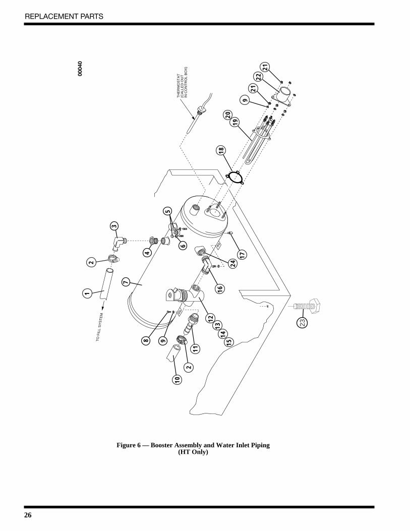
* When converting machine contact factory with serial number. Kit is supplied with new dataplate for machine. Factory will supply jumper settings for element at time of installation.
PSDR PRIME SWITCH DETERGENT, RINSEICR RELAYDDS DOOR SAFETY SWITCHRM RINSE MOTOR (IF USED)SRC CURRENT OPERATED START RELAY COILSS SERVICE SWITCHTM TIMER MOTORTP THERMAL PROTECTORWHT WHITEWHTR WATER HEATERWTS WATER THERMOSTAT
CT CONTACTORCTC CONTACTOR COILDM DETERGENT MOTORDP DRAIN PUMP (IF USED)DS DOOR SWITCHDV DRAIN VALVEEC/D EXTENDED CYCLE/DELIMEFV FILL VALVEGND GROUNDGRN GREENHTLS HIGH LIMIT THERMOSTATMSW MAIN SWITCH ON/FILL OFF/DRAIN
17
8
17
16 16
8
8
22CAM 6
NC
NORM
(IF USED)
21CAM 7
NO
NC
NC
DM
3
DSS
5
3
17
16PSDR
26
CAM 2NC
8NO
25
9 9
6
7
1CR
NO
NCCAM 1
NC
NO
33
8
NO 1
19
20
20
NO
NCCAM 5
DP
F V
(IF USED)
12
NO
SRC
3 WHT
3
GND
3
5GND
GRN
4
15
DRAIN14
BLK3
RED2
/RINSEWASH13
CLT
BLU
33
TM
1CR
3
3
3
TO CUSTOMER DISCONNECT SWITCH
MSW
NO4
2
1
CUSTOMER TO SUPPLY RATEDVOLTAGE/PHASE/Hz, AS SPECIFIEDPER ORDER, TO DISCONNECT SWITCH.ALL POWER SUPPLIED TO EACH CONNECTIONPOINT MUST COMPLY WITH ALL LOCALELECTRICAL CODES.
CLT CYCLE ON LIGHTDM DETERGENT MOTORDP DRAIN PUMP (IF USED)RL RELAYDV DRAIN VALVEFV FILL VALVEGND GROUNDGRN GREENHTLS HIGH LIMIT THERMOSTATMSW MAIN SWITCH ON/FILL OFF/DRAINPSDR PRIME SWITCH DETERGENT, RINSE
CUSTOMER TO SUPPLY RATEDVOLTAGE/PHASE/Hz, AS SPECIFIEDPER ORDER, TO DISCONNECT SWITCH.ALL POWER SUPPLIED TO EACH CONNECTIONPOINT MUST COMPLY WITH ALL LOCALELECTRICAL CODES.
00044
PSS PRIME SWITCH SANITIZERICR RELAYDSS REED SWITCHRM RINSE MOTOR (IF USED)SRC CURRENT OPERATED START RELAY COILSM SANITIZER MOTORTM TIMER MOTORTP THERMAL PROTECTORWHT WHITEWHTR WATER HEATERWTS WATER THERMOSTAT
PSS PRIME SWITCH SANITIZERICR RELAYDSS REED SWITCHRM RINSE MOTOR (IF USED)SRC CURRENT OPERATED START RELAY COILSM SANITIZER MOTORTM TIMER MOTORTP THERMAL PROTECTORWHT WHITEWHTR WATER HEATERWTS WATER THERMOSTAT
2
23
50
DSS
CAM 7NC
1CR
SM
22
18NO
CAM 617
NC
NO(IF USED)
RM
2
2
CAM 8NC
16NO
21 DM
20
CAM 4NO
NC
NC
D V20
(IF USED)
DP
2
2
GRN
2
GND
25
GND
14
13
CAM 5NO
F V19
9 SRC NO12
8 TM
WHT
BLK
RED
15
2 4
3
DRAIN 2
TP
MAIN
START CCW
BLU/RINSEWASH
1START CW
2
CLT CYCLE ON LIGHTDM DETERGENT MOTORDP DRAIN PUMP (IF USED)RL RELAYDV DRAIN VALVEFV FILL VALVEGND GROUNDGRN GREENHTLS HIGH LIMIT THERMOSTATMSW MAIN SWITCH ON/FILL OFF/DRAINPSDR PRIME SWITCH DETERGENT, RINSE
TO CUSTOMER RECEPTACLE
115V 60Hz
MSW
1
NO
1
1 2
8 CLT
GND
2
WHTBLK
PSS
34
17
4PSDR 16
CUSTOMER TO SUPPLY RATEDVOLTAGE/PHASE/Hz, AS SPECIFIEDPER ORDER, TO DISCONNECT SWITCH.ALL POWER SUPPLIED TO EACH CONNECTIONPOINT MUST COMPLY WITH ALL LOCALELECTRICAL CODES.
00045
L S
M
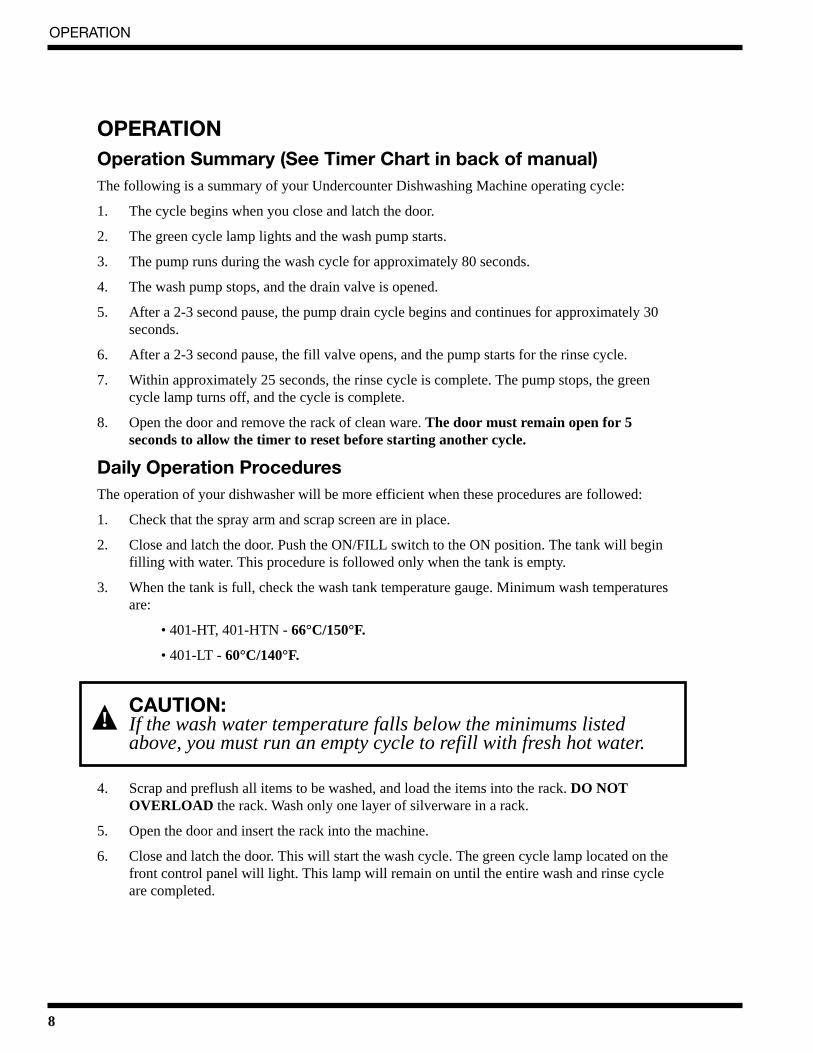
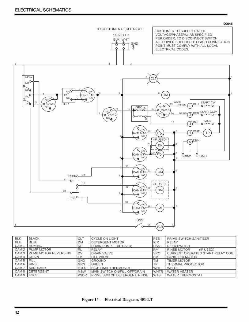
Figure 14 — Electrical Diagram, 401-LT
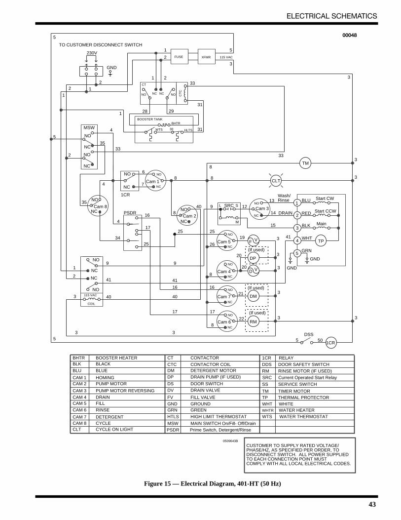
43
ELECTRICAL SCHEMATICS
TO CUSTOMER DISCONNECT SWITCH
230V
115 VAC
COIL
GND
22 1
1
1
1 2
2
1 5
3
4
4
6
7
4
1
3
3
40
41
9 9
16
17
16 16
8
3 3
5 50
3
5
4
3
1
2
3
3
3 41
8
17
3
40
41
17
19
15
33
3
3
3
33
3130
312928
14
1312
22
21
20
20
26
25
Cam 7
1CR
DSS
GND
GND
CLT
SRC
TP
TM
GRN
WHT
BLK
REDDRAIN
Wash/Rinse BLU
Main
Start CCW
Start CW
DM
DP
RM
D V
F V
(If used)
(If used)
Cam 4
Cam 5
Cam 3
Cam 6
5
5
5
MSW
NO
NO NONC NC
NO
NO
HLTSWTS
CT
FUSE XFMR 115 VAC
CT
C
BOOSTER TANKBHTR
NO
NC
NC
NC
NC
NC
NC
NC
NO
NC
NO
NC
NO
NC
NO
NC
NO
NC
NO
NO
NO
NOCam 8
Cam 1
Cam 2
NC
3533
35
34
2
PSDR
2
1CR
840 9 L S
M
8
88
(If used)
MSW MAIN SWITCH On/Fill- Off/Drain
BHTR BOOSTER HEATER
CTC CONTACTOR COIL
CT CONTACTOR
SS SERVICE SWITCH
PSDR Prime Switch, Detergent/Rinse
DS DOOR SWITCH
GRN GREEN
BLU BLUE
WHT WHITE
BLK BLACK
GND GROUNDFV FILL VALVE
DP DRAIN PUMP (IF USED)
DV DRAIN VALVE
DM DETERGENT MOTOR RM RINSE MOTOR (IF USED)
WHTR WATER HEATERHTLS HIGH LIMIT THERMOSTAT WTS WATER THERMOSTAT
TP THERMAL PROTECTOR
SRC Current Operated Start Relay
TM TIMER MOTOR
CAM 8 CYCLECAM 7 DETERGENT
CAM 6 RINSE
CAM 5 FILLCAM 4 DRAIN
CAM 3 PUMP MOTOR REVERSING
CAM 2 PUMP MOTORCAM 1 HOMING
CLT CYCLE ON LIGHT
1CR RELAY
DDS DOOR SAFETY SWITCH
0509643B
CUSTOMER TO SUPPLY RATED VOLTAGE/PHASE/HZ, AS SPECIFIED PER ORDER, TO DISCONNECT SWITCH. ALL POWER SUPPLIED TO EACH CONNECTION POINT MUST COMPLY WITH ALL LOCAL ELECTRICAL CODES.