96
TM 11-5985-370-12 TECHNICAL MANUAL OPERATOR’S AND ORGANIZATIONAL MAINTENANCE MANUAL ANTENNA GROUP OE-303/GRC (NSN 5985-01-152-5845) HEADQUARTERS, DEPARTMENT OF THE ARMY 19 JULY 1984

TM 11-5985-370-12
TECHNICAL MANUAL
OPERATOR’S AND ORGANIZATIONALMAINTENANCE MANUAL
ANTENNA GROUP OE-303/GRC(NSN 5985-01-152-5845)
HEADQUARTERS, DEPARTMENT OF THE ARMY 19 JULY 1984

TM 11-5985-370-12
BEFORE LEAVING YOUR BASE, MAKE SURE YOU HAVE:
ENOUGH WARNING SIGNS.
EXTRA STREAMERS OR APPROVED MARKERS.
A SUPPLY OF SPECIAL ANCHORS TO USE IN THE TYPE OF SOIL YOU MAY FIND INYOUR AREA OF OPERATIONS.
EXTRA GUY ROPES OR APPROVED SUBSTITUTES.

TM 11-5985-370-12
NEVER ERECT ANTENNA GROUP OE-303/GRCUNDER POWER LINES.
IF YOU MUST ERECT THIS ANTENNA NEAR POWERLINES, POWERTOWERS, POWER POLES OR BUILDINGS WITH OVERHEAD POWER
WIRES, FOLLOW THE RULE:
“DOUBLE THE HEIGHT OF THE TALLEST THING IN THE AREA”
EXAMPLE: If a powerline tower is 80 feet tall, (your antenna is 30 feet tall) DOUBLE 80
FEET to get a SAFE DISTANCE of 160 feet AWAY FROM the
powerline tower.
NEVER ATTEMPT TO ERECT THIS ANTENNA WITHOUT A TEAM OF TWOPERSONS AND THE NECESSARY HELP TO PROVIDE ADEQUATECONTROL OF FOOT AND VEHICLE TRAFFIC IN THE AREA DURINGANTENNA ERECTION.
ANDNEVER ERECT OR OPERATE THIS ANTENNA DURING AN ELECTRICAL STORM.
CLEARLY MARK THE ANTENNA AREA WITH SIGNS TO PREVENT PEOPLE ANDVEHICLES FROM DRIVING THROUGH THE AREA OR ATTEMPTING TO DRIVE UNDERTHE ANTENNA ITSELF. IT MAY BE NECESSARY TO POST SIGNS IN SEVERALLOCATIONS TO GET EFFECTIVE RESULTS.
IT MAY EVEN BE NECESSARY TO POST A GUARD OR WATCH DURING CERTAINTIMES (LIKE BLACKOUT OPERATIONS, BAD WEATHER, TROOP MOVEMENT).
YOUR SUPERVISOR SHOULD CONSULT WITH THE UNIT SAFETY OFFICER TO MAKESURE THAT ALL UNITS IN YOUR AREA ARE AWARE THAT YOUR LONG RANGEANTENNA IS TAKING UP A LARGE AREA AND TO BE CAREFUL.
MAKE SURE THE SOIL CAN SAFELY HOLD YOUR ANTENNA ANCHORS. IF THE SOIL ISLOOSE, MARSHY OR SANDY, IT MAY BE NECESSARY TO USE SPECIAL ANCHORS.USE OF SPECIAL ANCHORS IS COVERED IN THIS MANUAL.WHEN OPERATING UNDER UNUSUAL CONDITIONS, IT WILL BE NECESSARY TOKEEP A SHARP EYE ON ALL ANCHORS UNTIL THESE CONDITIONS PASS.
A

TM 11-5985-370-12
CLEARLY MARK ALL GUY WIRES, GUY ROPES AND THE ANTENNA WIRESWITH FLAGS OR STREAMERS.STRIPS OF CLOTH MAKE GOOD STREAMERS.
IF THE WEATHER IN YOUR AREA CAN CAUSE ICE TO FORM ON THEANTENNA, GUY WIRES AND GUY ROPES, ADD EXTRA GUYS TO SUPPORTTHE ANTENNA. CLEARLY MARK THE AREA WITH WARNING SIGNS LIKE— “BEWARE OF FALLING ICE”.
IF YOU SUSPECT THAT POWERLINES HAVE MADE ACCIDENTAL CON-TACT WITH YOUR ANTENNA - STOP OPERATION - TURN OFF THEEQUIPMENT- ROPE OFF OR HAVE SOME PERSON GUARD THE ANTENNAAREA - AND NOTIFY YOUR TEAM CHIEF.
WHEN SELECTING A SITE FOR YOUR ANTENNA, KEEP IN MIND THATYOU SHOULD SELECT GROUND WHICH WILL NOT ACCUMULATE WATERWHICH CAN REACH UP TO THE TRANSFORMERS USED AT EACH END OFTHE ANTENNA. THIS IS TO PREVENT A SHOCK HAZARD.
FUMES OF TRICHLOROTRIFLOUROETHANE ARE POISONOUS. PROVIDEADEQUATE VENTILATION WHENEVER YOU USE IT. DO NOT USE THISSOLVENT NEAR HEAT OR OPEN FLAME. TRICHLOROTRIFLOUROETHANEWILL NOT BURN, BUT HEAT TURNS THE SOLVENT INTO POISONOUSAND IRRITATING FUMES. DO NOT BREATHE THE FUMES OR VAPORS.THIS SOLVENT DISSOLVES NATURAL SKIN OILS. DO NOT GET THESOLVENT ON YOUR SKIN. USE GLOVES, SLEEVES AND AN APRONWHICH THE SOLVENT CANNOT PENETRATE. IF THE SOLVENT IS TAKENINTERNALLY, CONSULT A PHYSICIAN IMMEDIATELY. USE THIS SOLVENTONLY ON THE METAL MAST SECTIONS, DO NOT CLEAN THE TRAN-SFORMER HOUSINGS WITH THIS SOLVENT.
B

TM 11-5985-370-12
SAFETY STEPS TO FOLLOW IF SOMEONEIS THE VICTIM OF ELECTRICAL SHOCK
DO NOT TRY TO PULL OR GRAB THE INDIVIDUAL
IF POSSIBLE , TURN OFF THE ELECTRICAL POWER
IF YOU CANNOT TURN OFF THE ELECTRICALPOWER, PULL, PUSH, OR LIFT THE PERSON TOSAFETY USING A WOODEN POLE OR A ROPE ORSOME OTHER INSULATING MATERIAL
SEND FOR HELP AS SOON AS POSSIBLE
AFTER THE INJURED PERSON IS FREE OF
CONTACT WITH THE SOURCE OF ELECTRICALSHOCK, MOVE THE PERSON A SHORT DISTANCEA W A Y A N D I M M E D I A T E L Y S T A R T A R T I F I C I A LRESUSCITATION
C

TM 11-5985-370-12
HOW TO USETHIS MANUAL
This technical manual includes a cover index to assist you in locating the information you
need to operate and maintain Antenna Group OE-303/GRC.
In addition, this manual is also divided into chapters, sections and paragraphs which are
numbered sequentially.
Instructions on installation and use of this antenna equipment are presented in a detailed
sequence. DO NOT ATTEMPT ANY SHORT CUTS in installing and using this antenna
equipment. FOLLOW THE INSTRUCTIONS IN THIS MANUAL.
This antenna equipment has been designed to work with certain radio sets in a certain
frequency range. DO NOT ATTEMPT TO REDESIGN THIS ANTENNA. Follow the
specific DIMENSIONS and MEASUREMENTS in this manual.
D

TM 11-5985-370-12
TECHNICAL MANUALNO. 11-5985-370-12
HEADQUARTERS
DEPARTMENT OF THE ARMY
Washington, DC, 19 July 1984
OPERATOR’S AND ORGANIZATIONAL MAINTENANCE MANUAL
FOR ANTENNA GROUP OE-303/GRC(NSN 5985-01-152-5845)
REPORTING ERRORS AND RECOMMENDING IMPROVEMENTS
You can help improve this manual. lf you find any mistakes or if you know of away to improve the procedures, please let us know. Mail your letter, DA Form2028 (Recommended Changes to Publications and Blank Forms), or DA Form2028-2 located in the back of this manual direct to: Commander, US ArmyCommunications-Electronics Command and Fort Monmouth, ATTN: DRSEL-ME-MP Fort Monmouth, New Jersey 07703.
In either case, a reply will be furnished direct to you.
D
CHAPTER 1.S e c t i o n I .
Il.
Ill.
CHAPTER 2.
Sect ion I .
Il.
III.
IV .
V .
V I .
HOW TO USE THIS MANUAL
INTRODUCTIONGeneral Information
PAGE
1 - 1
Equipment Description
Principles of Operation
1-10
1-17
OPERATING INSTRUCTIONS
DescriPtion and Use of Operator's Controls
PMCS
Operation Under Normal Conditions
2 - 1
2 - 4
2 - 9
2 - 1 3
2 - 2 5
2 - 3 5
Antenna Erection
Orienting the Half -Rhombic Antenna
Operation Under Unusual Conditions
i
TM 11-5985-370-12
CHAPTERSect ion I .
CHAPTERSect ion I .
3. OPERATOR MAINTENANCETroubleshooting
4. ORGANIZATIONAL MAINTENANCE
3-1
Repair Parts and TMDEIl. PMCS
Ill. Troubleshooting
4-14-1
4-3IV. Maintenance Procedures 4-6
APPENDIX A ReferenceB Maintenance AllocationC Components of End ltem ListD Additional Authorization List (Not Applicable)
E Expendable Supplies and Materials List
A - 1
B - 1
C - 1
D - 1
E - 1
i i

TM 11-5985-370-12
CHAPTER 1
INTRODUCTION
SECTION I. GENERAL INFORMATION
1-1. SCOPE
This technical manual covers Antenna Group OE-303/GRC.
Instructions are given for:
installation (2 person team)
operation.
troubleshooting.
operator/crew maintenance.
organizational maintenance.
Antenna Group OE-303/GRC consists of 3 major items:
Antenna AS-3490/GRC.
Radio Frequency Cable Assembly CG-1889 C/U.
Mast Assembly AB-1244A/GRC.
1-1
TM 11-5985-370-12
Antenna Group OE-303/GRC has the following characteristics:
rugged.
lightweight.
directional radiation.
no adjustments required.
easy installation.
It cannot be overemphasized that this antenna must be used with caution. It occupies a
large area, Both foot and vehicular traffic must be controlled in the antenna area. The
CAUTIONS and WARNINGS in the manual give you specific instructions on how to
control traffic and to prevent accidents.
1-2
TM 11-5985-370-12
1-2. MAINTENANCE FORMS. RECORDS AND REPORTS
Reports of Maintenance and Unsatisfactory Equipment.
Department of the Army forms and procedures used for equipment maintenance will be those prescribed byDA Pam 738-750 as contained in the Maintenance Management Update. Air Force personnel will useAFR 66-1 for maintenance reporting and TO-00-35D54 for unsatisfactory equipment reporting. Navypersonnel will report maintenance performed utilizing the Maintenance Data Collection Subsystem (MDCS)IAW OPNAVINST 4790.2, VoI 3 and unsatisfactory material/conditions (UR submissions) IAW OPNAVINST4790,2, Vol 2, chapter 17.
Reporting of Packaging and Handling Deficienciews.
Fill out and forward SF 364 (Report of Discrepancy (ROD)) as prescribed in AR 735-11-2/DLAR4140.55/NAVMATINST 4355.73A/AFR 400-54/MCO 4430.3F.
Discrepancy In Shipment Report (DISREP) (SF 361).Fill out and forward Discrepancy in Shipment Report (DISREP) (SF 361) as prescribed in AR 55-38/NAVSUPINST 4610.33C/AFR 75-18/MCO P4610.19D/DLAR 4500.15.
1-3. DESTRUCTION OF ARMY ELECTRONICS MATERIEL
Destruction of Army electronics materiel to prevent enemy use shall be in accordance with TM 750-244-2,
1-4. ADMINISTRATIVE STORAGE
Administrative storage of equipment issued to and used by Army activities will have preventive maintenanceperformed in accordance with the PMCS chart before storing. When removing the equipment fromadministrative storage, the PMCS should be performed to assure operational readiness.
1-5. REPORTING EQUIPMENT IMPROVEMENT RECOMMENDATIONS (EIR)
If your equipment needs improvement, let us know. Send us an EIR. You, the user are the only one who can tell uswhat you don’t like about your equipment. Let us know why you don’t like the design. Put in on SF 368 (QualityDeficiency Report). Mail it to Commander, U.S. Army Communications-Electronics Command and FortMonmouth, ATTN: DRSEL-ME-MP, Fort Monmouth, NJ 07703. We’ll send you a reply.
1.6. WARRANTY INFORMATlON
Certain items of equipment are covered under a special warranty. Your C-E ORG MAINT team should have thenecessary information for identifying which items are protected and the procedures for getting warrantyrepair and/or replacement.
1-3
TM 11-5985-370-12
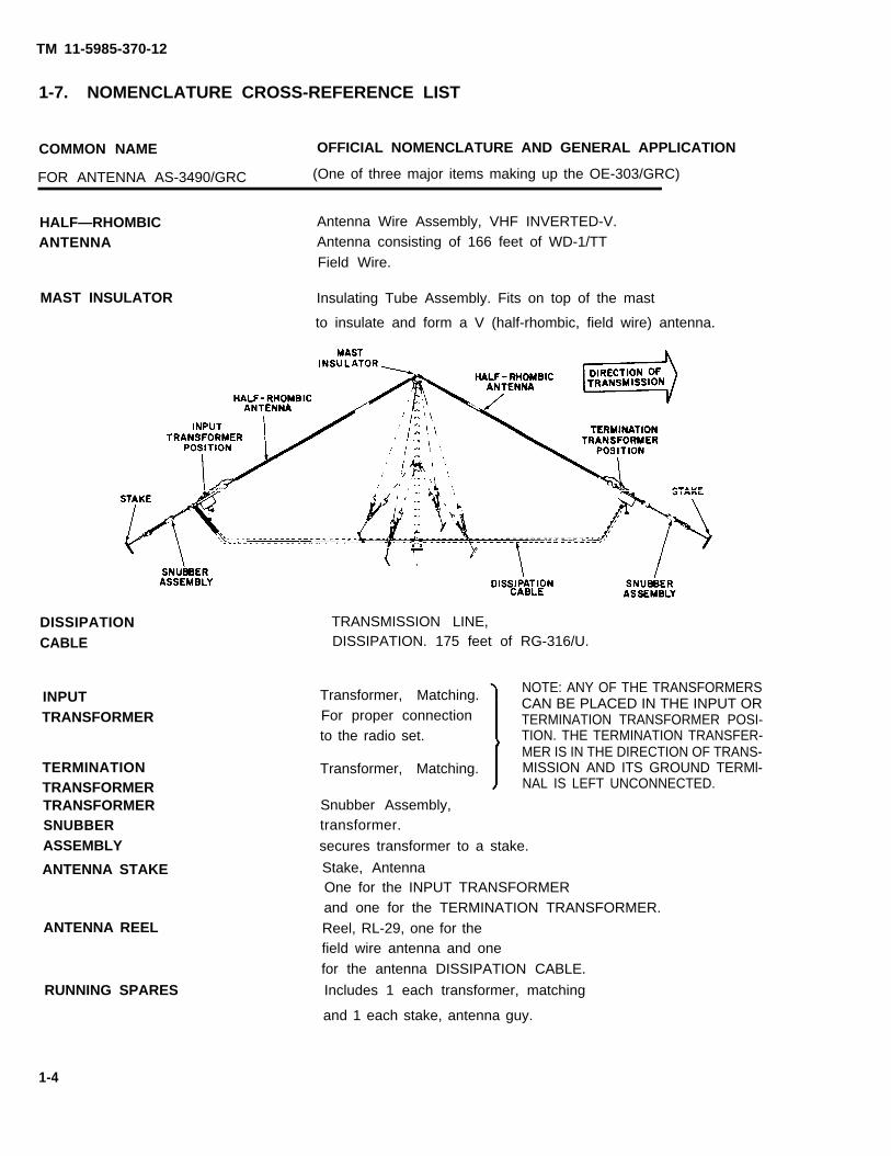
1-7. NOMENCLATURE CROSS-REFERENCE LIST
COMMON NAME OFFICIAL NOMENCLATURE AND GENERAL APPLICATION
FOR ANTENNA AS-3490/GRC (One of three major items making up the OE-303/GRC)
HALF—RHOMBIC Antenna Wire Assembly, VHF INVERTED-V.
ANTENNA Antenna consisting of 166 feet of WD-1/TTField Wire.
MAST INSULATOR Insulating Tube Assembly. Fits on top of the mast
to insulate and form a V (half-rhombic, field wire) antenna.
DISSIPATION TRANSMISSION LINE,
CABLE DISSIPATION. 175 feet of RG-316/U.
INPUTTRANSFORMER
Transformer, Matching. NOTE: ANY OF THE TRANSFORMERSCAN BE PLACED IN THE INPUT OR
For proper connection TERMINATION TRANSFORMER POSI-to the radio set. TION. THE TERMINATION TRANSFER-
MER IS IN THE DIRECTION OF TRANS-TERMINATION Transformer, Matching. MISSION AND ITS GROUND TERMl-TRANSFORMER NAL IS LEFT UNCONNECTED.
TRANSFORMER Snubber Assembly,SNUBBER transformer.ASSEMBLY secures transformer to a stake.
ANTENNA STAKE Stake, AntennaOne for the INPUT TRANSFORMERand one for the TERMINATION TRANSFORMER.
ANTENNA REEL Reel, RL-29, one for thefield wire antenna and onefor the antenna DISSIPATION CABLE.
RUNNING SPARES Includes 1 each transformer, matching
and 1 each stake, antenna guy.
1-4

TM 11-5985-370-12
1-7. NOMENCLATURE CROSS-REFERENCE LIST (Continued)
COMMON NAME OFFICIAL NOMENCLATURE AND GENERAL APPLICATION
FOR RADIO FREQUENCY CABLE ASSEMBLY CG-1889C/U. The second of three major items making upAntenna Group OE-303/GRC
RADIO CABLE
RADIO CABLEEND CONNECTOR
Connector, RF.
RADIO CABLEADAPTER
ANTENNA TRANSITBAG
Cable Assembly, RF.50 feet of RG-213/U coaxial cable.Used to connect the INPUT TRANSFORMER on theHALF—RHOMBIC ANTENNA to the radio set.
One connector is permanently installed oneach end of the RADIO CABLE.
Connector Adapter, Part Number TRU 2064-1.A type N female to BNC male adapter.
Required to connect certain radio that cannotaccept the permanently attached RADIO CABLEEND CONNECTOR .
BAG, transit.Holds two major itemsin Antenna Group OE-303/GRC.
1-5

TM 11-5985-370-12
7.1 NOMENCLATURE CROSS-REFERENCE LIST (Continued)
FOR MAST ASSEMBLY AB-1244A/GRC. The third item making up ANTENNA GROUP OE-303/GRC.
COMMON NAME OFFICIAL NOMENCLATURE AND GENERAL APPLICATION
MAST AND BASEASSEMBLY
MAST BASE PLATE
MAST BASE STAKE
LOWER MAST SECTION
LOWER ADAPTERASSEMBLY
LOWER GUY PLATE
UPPER MAST SECTION
UPPER ADAPTERASSEMBLY
UPPER GUY PLATE
UPPER GUYASSEMBLY
LOWER GUYASSEMBLY
Mast and Base Assembly, 1 each.Lower part is a Stake.Upper part is a movable short mast.
Plate, 1 each.The base for the Mast Assembly.
Stake, 2 each.Secure Mast Base Plate.
Mast Section Assembly, Lower, 5 each.Form bottom part of mast.
Adapter Assembly, Lower, 1 each.For properly holding the Lower Guy Plate.
Guy Plate, 1 each.Holds 4 Lower Guy Assemblies.
Mast Section Assembly, Upper, 5 each.Form top part of mast.
Adapter Assembly, Upper, 1 each.For properly holding the Upper Guy Plate.
Guy Plate, 1 each.Holds 4 Upper Guy Assemblies.
Guy Assembly, 4 each.Color Code = Red.
Guy Assembly, 4 each.Color Code = Blue.
1-6

GUY STAKE
RL-28 REEL
HAMMER
MAST TRANSIT BAG
16 STRAIN CLAMP
NOTE: Items used with the LOWER MAST
TM 11-5985-370-12
Stake Assembly, 4 Each.Secure the 4 Upper and 4 Lower Guy Assemblies.
Reel, RL-28, 2 each, for the GUY ASSEMBLIES.
Hammer, 1 each, 2½ pound.
Bag, Transit, 1 each, for all Mast AB-1224A/GRC items.
Clamp, electrical, conductor, strain. 1 each is issuedbut not used with the OE-303/GRC.
SECTIONS and the LOWER GUYS are associated with Blue
markings on components. Items used with the UPPER MAST SECTIONS and the UPPER GUYS are
associated with Red markings on components.
1-7

TM 11-5985-370-12
1-7. NOMENCLATURE CROSS-REFERENCE LIST (Continued)
COMMON NAME OFFICIAL NOMENCLATURE
MULTIMETER Multimeter AN/USM-223.
TOOL KIT Tool Kit, Electronic, TK-100/G.
(NOT SHOWN)
COMPASS Compass, Magentic.
1-8
TM 11-5985-370-12
1-8. LIST OF ABBREVIATIONS
MHZ
RF
V H F
PMCS
. . . . . . . . . . . . . . . . . . . . . . . . . . . . . . . . . . . . . . . . . . . . . . . . . . . . . . . . . . . . . . . . . . . . . . . . . . . . . . . . . . . Megahertz
. . . . . . . . . . . . . . . . . . . . . . . . . . . . . . . . . . . . . . . . . . . . . . . . . . . . . . . . . . . . . . . . . . . . . . . . . . . . . . . . Radio Frequency
. . . . . . . . . . . . . . . . . . . . . . . . . . . . . . . . . . . . . . . . . . . . . . . . . . . . . . . . . . . . . . . . . . . . . . . . . . Very High Frequency
. . . . . . . . . . . . . . . . . . . . . . . . . . . . . . . . . . . . . . . . . . . . . . . . . . Preventive Maintenance Checks and Services
1-9. GLOSSARY
BIDIRECTIONAL Any two opposite directions.
CEOI Communication Electronics Operating Instructions
CONFIGURATION Arrangement or hook-up.
DISSIPATION LINE A cabLe connected to form a resistance and to get rid of heat.
HALF-RHOMBIC One half of a Rhombus.
HORIZONTAL POLARIZATION A radio wave front from a horizontal antenna.
OMNIDIRECTIONAL All directions.
RHOMBIC A rhombus or diamond shape.
UNIDIRECTIONAL Any ONE DIRECTION.
VERTICAL POLARIZATION A radio wave front from a vertical antenna.
1-9

TM 11-5985-370-12
SECTION Il. EQUIPMENT DESCRIPTION
1-10. EQUIPMENT PURPOSE, CAPABILITIES AND FEATURES
Designed to provide greater range for two families of VHF radios:AN/VRC-12 series of venicular radio sets:
Includes AN/VRC-12, AN/VRC-43, AN/VRC-44, AN/VRC-45, AN/VRC-46, AN/VRC-47, AN/VRCAN/VRC-49.
AND
Early model (partial solid state) portable radio sets
Includes AN/PRC-25, AN/VRC-53 and AN/GRC-125.
OR
Late Model (all solid state) portable radio sets:
-48,
Includes AN/PRC-77, AN/VRC-64 and AN/GRC-160.
1-10

TM 11-5985-370-12
Simple design:
No complicated parts.
Simple connection to a radio set.
Easy to erect.
Easy to disassemble.
Rugged enough to stay in a location for a long time.
Easlly transported in 2 TRANSIT BAGS.
The HALF-RHOMBIC ANTENNA IS A VERTICAL ANTENNA.
It is a vertically polarized antenna.
Radiation pattern is UNIDIRECTIONAL:
The end of the HALF RHOMBIC ANTENNA with the TERMINATION TRANSFORMER pointsin the direction of BEST TRANSMISSION AND RECEPTION.
The UNIDIRECTIONAL characteristic of the HALF RHOMBIC ANTENNA also provides:
Greater Range
AND
More secure operating conditions.
You can greatly reduce your signal towards the enemy by properly orienting your antenna.
DO NOT GUESS WHICH DIRECTION IS WHICHWHEN ORIENTING YOUR ANTENNA. USE YOUR
MAPS AND COMPASS TO GET SAFE ORIENTATION.
1-11

TM 11-5985-370-12
1-11. TYPICAL LAYOUT OF ANTENNA GROUP OE-303/GRC IN A FIELD OPERATION
MAST ASSEMBLY AB-1244A/GRC
30+ feet tall.
30 Same assembly is used on Antenna Groups OE-254/GRC.
1-12

TM 11-5985-370-12
HALF-RHOMBIC ANTENNA
166 feet of Field Wire, WD1/TT.
MAST INSULATOR
Insulates the HALF RHOMBIC ANTENNA from the MAST.
INPUT TRANSFORMER
Provides proper electrical connection to the HALF-RHOMBIC ANTENNA.
RADIO CABLE
.50 feet of coaxial cable RG-213/U.
RADIO SET
l Any one of the AN/VRC-12 series of radio sets
O R
l Any one of the AN/PRC-25 or AN/PRC-77 series of radio sets.
DISSIPATION CABLE
175 feet of coaxial cable RG-316/lJ.
This cable acts as a large dissipation and termination resistor when it is connected to the other end of
the HALF-RHOMBIC ANTENNA through the TERMINATION TRANSFORMER.
TERMINATION TRANSFORMER
l Provides proper electrical matching for connecting the DISSIPATION CABLE to the other end of the
HALF-RHOMBIC ANTENNA.
TRANSFORMER SNUBBER ASSEMBLY (one for each transformer)
S e c u r e s T r a n s f o r m e r t o S t a k e .
1-13

TM 11-5985-370-12
1-12. EQUIPMENT DATA
DIMENSIONS AND WEIGHTS
WEIGHT OF ENTIRE ANTENNA SYSTEM
50 pounds (including the 2 TRANSIT BAGS).
HEIGHT OF ANTENNA
Approximately 31 feet to top of MAST ASSEMBLY.
ELECTRONIC CHARACTERISTICS
FREQUENCY RANGE
Designed to operate in the 30 mHz to 88 mHz VHF range.
RF POWER CAPABILITY
350 Watts.
OPERATING CONDITIONS
Rugged enough to operate in all theatres of operation.
VERTICAL RADIATION PATTERN
This HALF-RHOMBIC ANTENNA produces a very desirable VERTICAL ANGLE RADIATIONPATTERN:
Including good signal from approximately 6 degrees UP to 10 degrees.
1-14
TM 11-5985-370-12
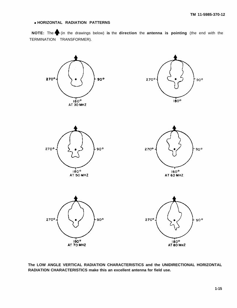
HORIZONTAL RADIATION PATTERNS
NOTE: The (in the drawings below) is the direction the antenna is pointing (the end with the
TERMINATION TRANSFORMER).
The LOW ANGLE VERTICAL RADIATION CHARACTERISTICS and the UNIDIRECTIONAL HORIZONTALRADIATION CHARACTERISTICS make this an excellent antenna for field use.
1-15
TM 11-5985-370-12
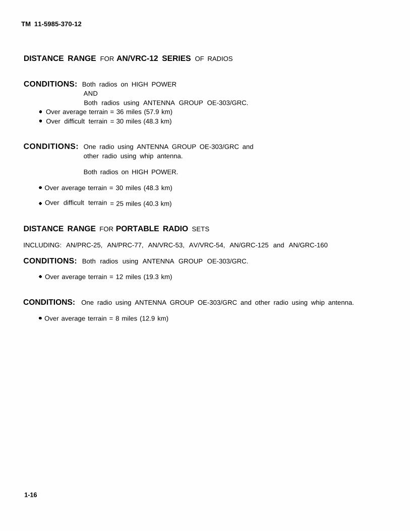
DISTANCE RANGE FOR AN/VRC-12 SERIES OF RADIOS
CONDITIONS: Both radios on HIGH POWERANDBoth radios using ANTENNA GROUP OE-303/GRC.
Over average terrain = 36 miles (57.9 km)Over difficult terrain = 30 miles (48.3 km)
CONDITIONS: One radio using ANTENNA GROUP OE-303/GRC andother radio using whip antenna.
Both radios on HIGH POWER.
Over average terrain = 30 miles (48.3 km)
Over difficult terrain = 25 miles (40.3 km)
DISTANCE RANGE FOR PORTABLE RADIO SETS
INCLUDING: AN/PRC-25, AN/PRC-77, AN/VRC-53, AV/VRC-54, AN/GRC-125 and AN/GRC-160
CONDITIONS: Both radios using ANTENNA GROUP OE-303/GRC.
Over average terrain = 12 miles (19.3 km)
CONDITIONS: One radio using ANTENNA GROUP OE-303/GRC and other radio using whip antenna.
Over average terrain = 8 miles (12.9 km)
1-16
TM 11-5985-370-12
SECTION Ill. PRINCIPLES OF OPERATION
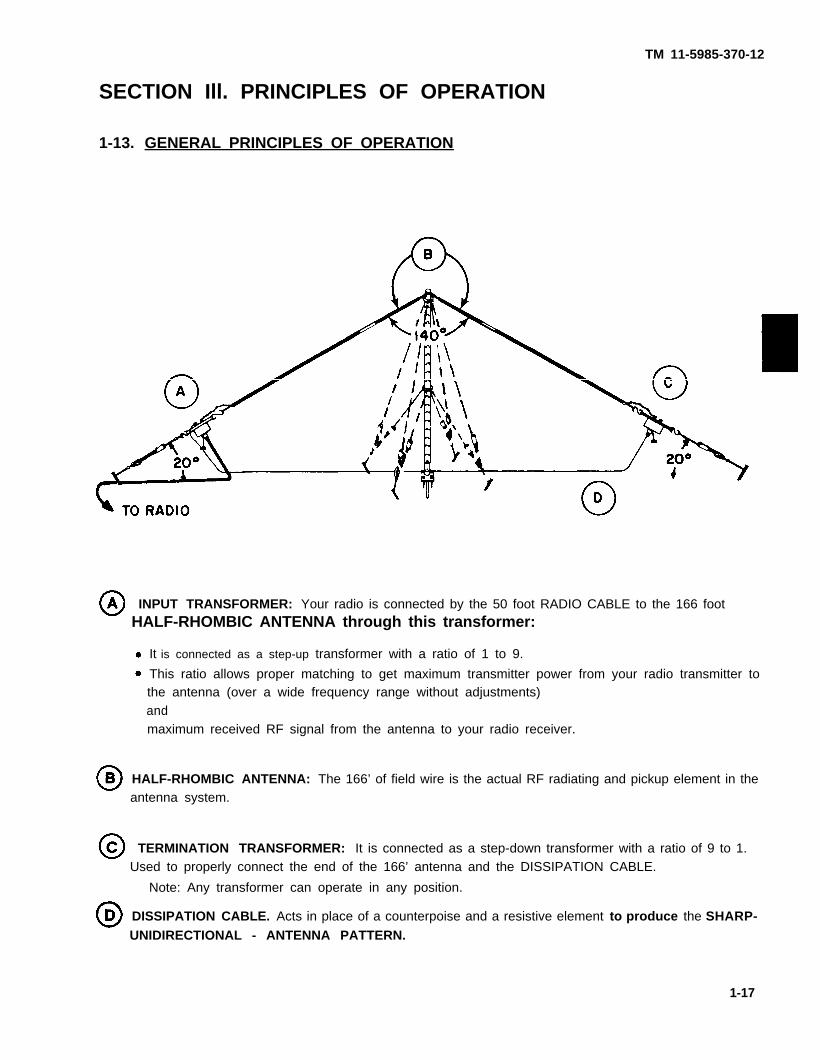
1-13. GENERAL PRINCIPLES OF OPERATION
INPUT TRANSFORMER: Your radio is connected by the 50 foot RADIO CABLE to the 166 footHALF-RHOMBIC ANTENNA through this transformer:
It is connected as a step-up transformer with a ratio of 1 to 9.
This ratio allows proper matching to get maximum transmitter power from your radio transmitter tothe antenna (over a wide frequency range without adjustments)andmaximum received RF signal from the antenna to your radio receiver.
HALF-RHOMBIC ANTENNA: The 166’ of field wire is the actual RF radiating and pickup element in theantenna system.
TERMINATION TRANSFORMER: It is connected as a step-down transformer with a ratio of 9 to 1.Used to properly connect the end of the 166’ antenna and the DISSIPATION CABLE.
Note: Any transformer can operate in any position.
DISSIPATION CABLE. Acts in place of a counterpoise and a resistive element to produce the SHARP-UNIDIRECTIONAL - ANTENNA PATTERN.
1-17

TM 11-5985-370-12
Characteristics of the HALF-RHOMBIC ANTENNA
Broad band (no need to change the length of the WD-1/TT Field Wire).
Good noise and interference rejection.
Simple construction.
Highly desirable UNIDIRECTIONAL horizontal radiation pattern with a LOW ANGLE verticalradiation pattern.
Remember, the HALF RHOMBIC ANTENNA operates in a UNIDIRECTIONAL PATTERN with VERTICALPOLARIZATION.
FOR BEST RESULTS:
AND
BOTH RECEPTION AND TRANSMISSION WILL BE IMPROVED IF THE DISTANT STATION USES AVERTICAL ANTENNA.
1-18

TM 11-5985-370-12
CHAPTER 2
OPERATING INSTRUCTIONSSECTION 1. DESCRIPTION AND USE OF OPERATOR’S
CONTROLS, INDICATORS AND RECEPTACLES.
2-1. OPERATOR’S RECEPTACLES ON THE RADIO CABLE.
2-1
TM 11-5985-370-12
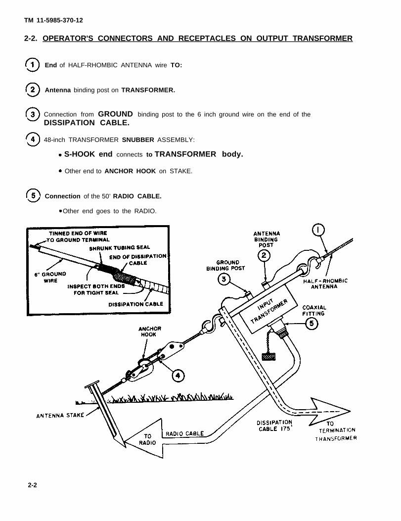
2-2. OPERATOR'S CONNECTORS AND RECEPTACLES ON OUTPUT TRANSFORMER
End of HALF-RHOMBIC ANTENNA wire TO:
Antenna binding post on TRANSFORMER.
Connection from GROUND binding post to the 6 inch ground wire on the end of theDISSIPATION CABLE.
48-inch TRANSFORMER SNUBBER ASSEMBLY:
S-HOOK end connects to TRANSFORMER body.
Other end to ANCHOR HOOK on STAKE.
Connection of the 50’ RADIO CABLE.
Other end goes to the RADIO.
2-2

2-3. OPERATOR’S CONNECTORS AND RECEPTACLES ON TERMINATIONTRANSFORMER
TM 11-5985-370-12
End of HALF-RHOMBIC ANTENNA (Field Wire WD-1/TT) connected to:
ANTENNA binding post (push-to-connect) on Transformer.
Ground binding post, NO CONNECTION TO BE MADE (when the Transformer is in the
TERMINATION TRANSFORMER POSITION).
48 inch TRANSFORMER SNUBBER ASSEMBLY:
S-HOOK end connects to TRANSFORMER body.
Other end to ANCHOR HOOK on STAKE.
Connection for the 175’ DISSIPATION CABLE.
Using Connector Adapter, UG-201 A/U.
2-3

TM 11-5985-370-12
SECTION Il. OPERATOR/CREW
PREVENTIVE MAINTENANCE CHECKS AND SERVICES
2.4 General
To be sure that your equipment is always ready for your mission, you must do scheduled PreeventiveMaintenance Checks and Services (PMCS) as outlined in Table 2-1.
BEFORE OPERATION perform your PMCS to be sure that your equipment is ready to go.
DURING OPERATION perform your PMCS. This should help you spot small problems before theybecome big problems.
AFTER OPERATION perform your PMCS. This should help keep your equipment in top shape.
WEEKLY AND MONTHLY PMCS are important checks you make to keep serious problems fromsuddenly happening.
ROUTINE CHECKS AND SERVICES are not listed in your PMCS TABLE. These routine checks andservices should be done anytime you see that they are necessary. Examples of routine checks are:
Cleaning, dusting, washing and spot painting
Checking for loose or binding controls, covering unused receptacles, stowing items when not in use.
Checking for loose hardware, mountings and straps.
Inventorying equipment, periodic operational checks.
If you find what you considers routine check in the PMCS TABLE, it was listed because others have reported itas a critical problem.
2-4

TM 11-5985-370-12
2-5. USE OF DA FORM 2404 FOR PMCS
If your equipment must be in operation all the time, check and service those items that can be checkedand serviced without disturbing operation. Make the complete checks and services when theequipment is shut down.
Use the ITEM NO. column in your PMCS TABLE 2-1 to get the numbers for the TM ITEM NO.column on DA FORM 2404. (Equipment Inspection and Maintenance Worksheet) when you fill out theform.
The PROCEDURES column in your PMCS TABLE 2-1 instructs you to CHECKAND HAVE REPAIRED OR ADJUSTED AS NECESSARY. Carefully follow theseinstructions - AND - REMEMBER, YOU ARE NOT AUTHORIZED TO OPEN UP
ANY UNIT.
WHEN YOU ARE DOING ANY PMCS OR ROUTINE CHECKS,KEEP IN MIND ALL OF THE WARNINGS AND CAUTIONS INTHIS MANUAL.
DO NOT USE TRICHLOROTRIFLOUROETHANE TO CLEAN THE TRANS-FORMERS.
2-5

Table 2-1.
TM
11-5985-370-12
2-6

TM
11-5985-370-12
2-7

TM
11-5985-370-12
2-8

TM 11-5985-370-12
SECTION III. OPERATION UNDER NORMAL CONDITIONS
BEFORE INSTALLING AND USING THIS ANTENNA, CAREFULLY READ THEFOLLOWING WARNINGS.
CLEARLY MARK ALL GUY WIRE, GUY ROPES AND THE ANTENNA WIRESWITH FLAGS OR STREAMERS.STRIPS OF CLOTH MAKE GOOD STREAMERS.
IF THE WEATHER IN YOUR AREA CAN CAUSE ICE TO FORM ON THEANTENNA, GUY WIRES AND GUY ROPES, ADD EXTRA GUYS TO SUPPORTTHE ANTENNA. CLEARLY MARK THE AREA WITH WARNING SIGNS LIKE— “BEWARE OF FALLING ICE”.
WHEN SELECTING A SITE FOR YOUR ANTENNA, KEEP IN MIND THATYOU SHOULD SELECT GROUND WHICH WILL NOT ACCUMULATE WATERWHICH CAN REACH UP TO THE TRANSFORMERS USED AT EACH END OFTHE ANTENNA. THIS IS TO PREVENT A SHOCK HAZARD.
2-9

TM 11-5985-370-12
FUMES OF TRICHLOROTRIFLOUROETHANE ARE POISONOUS. PROVIDEADEQUATE VENTILATION WHENEVER YOU USE IT. DO NOT USE THISSOLVENT NEAR HEAT OR OPEN FLAME. TRICHLOROTRIFLOUROETHANEWILL NOT BURN, BUT HEAT TURNS THE SOLVENT INTO POISONOUSAND IRRITATING FUMES. DO NOT BREATHE THE FUMES OR VAPORS.THIS SOLVENT DISSOLVES NATURAL SKIN OILS. DO NOT GET THESOLVENT ON YOUR SKIN. USE GLOVES, SLEEVES AND AN APRONWHICH THE SOLVENT CANNOT PENETRATE. IF THE SOLVENT IS TAKENINTERNALLY, CONSULT A PHYSICIAN IMMEDIATELY. USE THIS SOL-VENT ONLY ON THE METAL MAST SECTIONS, DO NOT CLEAN THETRANSFORMER HOUSINGS WITH THE SOLVENT.
2-10

TM 11-5985-370-12
2.6. ANTENNA SITE SELECTlON
Because this antenna is highly directional, many potential antenna sites may not be suitable.
Before making any site selection, you should know:The direction of transmission (or the magnetic azimuth for the distant station).
The paths and tracks of both foot and vehicle traffic in the antenna area.
Select a site with NO OBSTRUCTIONS in the direction of transmission.Examples of obstructions are:
Tall trees.
Buildings.
Hills and mountains,
It isc a good idea to select both a primary and alternate antenna site. Then, if any problems arise at the primary
site, a quick move can be made to the alternate site.
Remember, sites must be within 50 feet of the radio. Only 50 feet of cable is available to connect the
radio to the antenna.
2-7. ANTENNA SITE INSPECTION
Before making a final site selection, carefuily inspect the three Site areas which you will use tosecure your stakes.
In the antenna site area example below, INSPECT:
AREA A, the center of the site area where you will locate the stakes for the antenna mast.
AREA B and AREA C where you will locate the antenna stakes.
The three stake areas should be usable.Examples:
The soil should be able to
hold your stakes.
The area should be free
of small trees, shrubsand undesirable foliage.Poison ivy is an example
of undesirable foliage.
2-11

TM 11-5985-370-12
2-8. PRELIMINARY STEPS
Before you leave your base, make sure you have:
Usable maps for your area of operations.
A working hand-held compass.
A CURRENT CEOI.
It is also a good idea to take along:
A supply of WARNING SIGNS.
Extra cloth for streamers.
A suppIy of special stakes to use in the type of terrain you may find in your area of operations.
Measurement standard, short/long.
Antenna site selection and antenna erection should be rehearsed as much as possible. This practice is very
important when team members change.
To help you when practicing antenna site selection and antenna erection, you should make use of 20 foot and
83 foot standards of length to help you make accurate stake placement.
These standards can be very helpful during night operations.
Examples of a 20 foot SHORT STANDARD (to accurately place mast guy stakes) are:
A 40 foot GUY LINE (COLOR CODE RED) folded in half.
A 20 foot length of field wire. Make sure it is tagged.
An 83 foot length of field wire makes a good long standard for establishing the location of the two
HALF–RHOMBIC ANTENNA stakes.
2-12

TM 11-5985-370-12
Section IV. ANTENNA ERECTION2-9. ASSEMBLY AND INSTALLATION OF MAST AB-1244A/GRC AND ANTENNA
AS-3490/GRC
Orienting the HALF-RHOMBIC ANTENNA (as described in paragraph 2-6) must be done before orientingMAST AB-1244A/GRC.
PLACE the MAST PLATE (ribs
up) with its center in the approximate
center of the erection area.
Drive the stake part of MAST AND BASE
ASSEMBLY - through the center hole ofthe MAST BASE PLATE - into the ground.
Secure the MAST BASE PLATE with the
two MAST BASE STAKES.
2-13

TM 11-5985-370-12
PLACE a short STANDARD (20’) over the
short MAST of the MAST AND BASE
ASSEMBLY and stretch out the STANDARD.
Locate four points, each 90 degreesapart - 20 feet away from the mast
AND
permanently install 4 GUY STAKES,use the HAMMER.
Position the movable short MAST on theMAST AND BASE ASSEMBLY so it lays onthe MAST BASE PLATE in the
direction the mast will
be assembled.
Assemble the 5 LOWER MAST sections (insert the keyed male end into the keyedfemale end).
Add the assembled 5 LOWER MAST SECTIONS to the short MAST on the MAST AND BASEASSEMBLY.
2-14

TM 11-5985-370-12
Slide the LOWER GUY PLATE (color code BLUE) onto the male end of the LOWERADAPTER ASSEMBLY.
Add the LOWER ADAPTER ASSEMBLY WITH the installed LOWER GUY PLATEto the masts on the ground.
Assemble the 5 UPPER MAST SECTIONS AND join them to the masts on theground.
Slide the UPPER GUY PLATE (color code RED) onto the male end of the UPPERADAPTER ASSEMBLY.
2-15
TM 11-5985-370-12
Add the UPPER MAST ADAPTER ASSEMBLY with the installed UPPER GUY PLATEto the masts on the ground.
Turn both the UPPER and LOWER GUY PLATES so that one hole is uppermost:
4 holes will be used to connect the GUY HOOKS.
HOLE 1 for FRONT GUY HOOK -
hole 3 for BACK GUY HOOK -
HOLES 2 and 4 for SIDE GUY HOOKS -
CAUTION
USE HOLES THAT ARE 90 DEGREES APART.SOME PLATES MAY HAVE A FIFTH HOLE
WHICH WILL NOT BE USED.
Attach each of the 4 GUY HOOKS (color code BLUE) to the proper hole onthe LOWER GUY PLATE.
2-16

TM 11-5985-370-12
Carefully and neatly:
Extend the other end of each“SIDE” GUY rope (holes 2 and 4)towards the appropriate “SIDE”GUY STAKE.
(the other end contains the GUY SNUBBERand the GUY LOOP)
Attach each GUY rope LOOP to anANCHOR HOOK which is attached to theend of each GUY STAKE’S stringer.
Carefully and neatly: attach each of the 4 GUY HOOKS (color code RED) to the properhole on the UPPER GUY PLATE.
2-17

TM 11-5985-370-12
Carefully and neatly: extend the other end of each “SIDE” GUY rope (holes 2 and 4)towards the appropriate SIDE GUY STAKE.(the other end contains the GUY SNUBBER and the GUY LOOP)
Carefulty attach each GUY "SIDE" GUY LOOP to an ANCHOR HOOK attached to the
end of each GUY STAKE’S stringer.
NOTE: Each ANCHOR HOOK on each GUY STAKE will hold one GUY LOOP of a LOWERGUY and one GUY LOOP of an UPPER GUY.
2-18
TM 11-5985-370-12
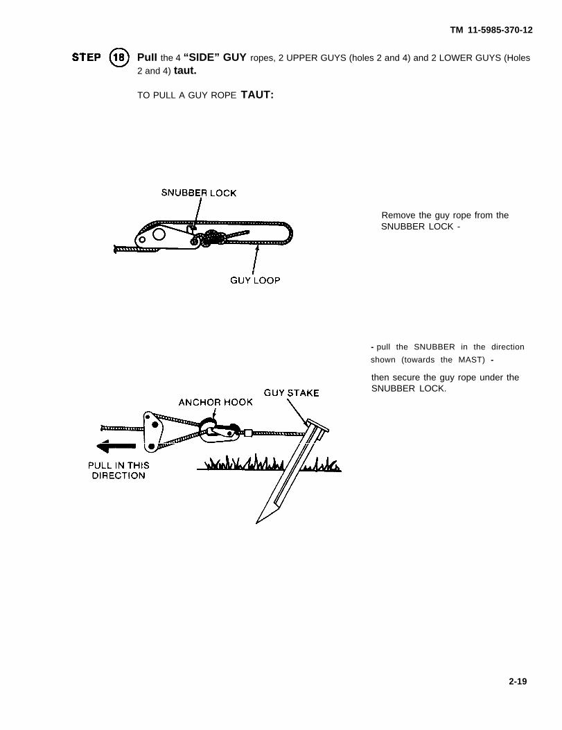
PuII the 4 “SIDE” GUY ropes, 2 UPPER GUYS (holes 2 and 4) and 2 LOWER GUYS (Holes2 and 4) taut.
TO PULL A GUY ROPE TAUT:
Remove the guy rope from theSNUBBER LOCK -
- pull the SNUBBER in the direction
shown (towards the MAST) -
then secure the guy rope under theSNUBBER LOCK.
2-19

TM 11-5985-370-12
Adjust the UPPER "BACK" GUY (hole 3) and LOWER "BACK" GUY (hole 3):
Lay them alongside one set of TAUT "SIDE" GUYS and adjust the "BACK" GUYS to the same
length.
Attach the GUY LOOPS of the UPPER "BACK" GUY and the LOWER "BACK" GUY to theANCHOR HOOK on the "BACK" GUY STAKE. THE BACK GUYS WILL NOT BE TAUT
AT THIS TIME.
NOTE: This now leaves the "FRONT" LOWER GUY rope and the “FRONT” UPPER GUY
rope free and unconnected. You will use these free GUYS during erection. The other
3 LOWER GUYS and 3 UPPER GUYS are now connected to GUY STAKES.
2-20

TM 11-5985-370-12
Install the plastic HALF-HOMBIC ANTENNA MAST INSULATOR on top of theMAST.
Feed one-half of the field wire antenna (83’) through the MAST INSULATOR(Approximately midway between the white markers),
Carefully and neatly: spread the 83’ of field wire antenna on each side of the MAST, as farout of the way as possible.
2-21

TM 11-5985-370-12
2.8 ANTENNA ERECTlON
REVIEW ALL THE WARNINGS IN THE FRONT OFTHIS MANUAL AND IN SECTION Ill OF THISCHAPTER. DO NOT TAKE ANY SHORT CUTS.
Double check the eight GUYS (4 UPPER, color coded RED and 4 LOWER, color coded BLUE)
2 LOWER “SIDE” GUYS and 2 UPPER “SIDE” GUYS should be taut.
1 LOWER and 1 UPPER “BACK” GUY LOOP should be connected to the BACK GUY STAKE
- BUT - not taut.
1 LOWER and 1 UPPER “FRONT” GUY should be free for use during erection.
AND
Make sure the 83' of field wire antenna on each side of the MAST INSULATOR is untangled and laying
loosely on the ground.
2-22
TM 11-5985-370-12
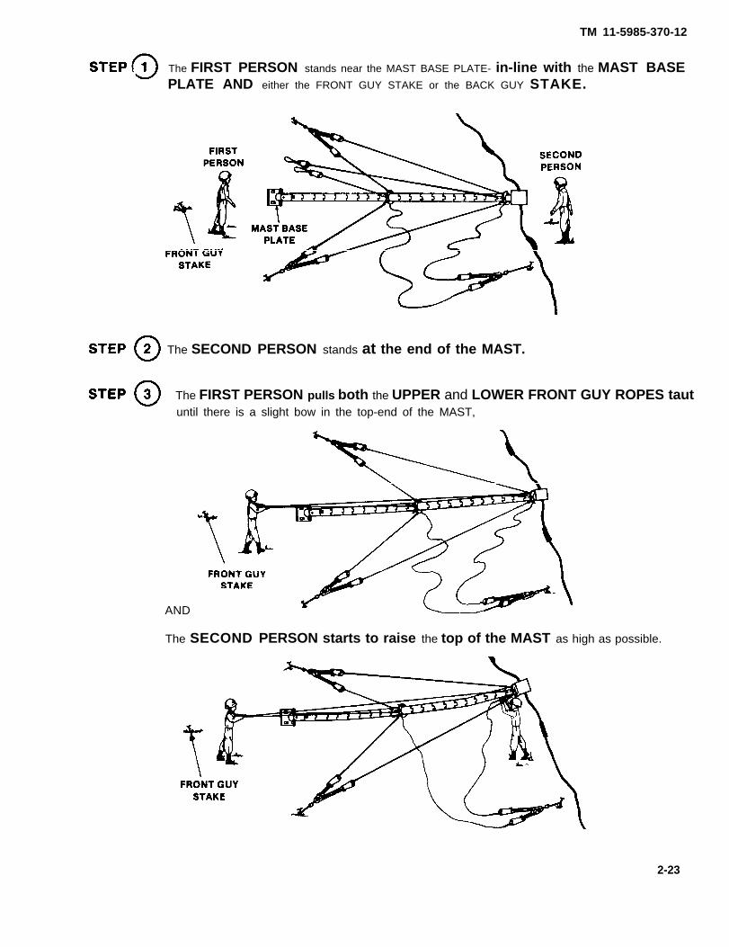
The FIRST PERSON stands near the MAST BASE PLATE- in-line with the MAST BASEPLATE AND either the FRONT GUY STAKE or the BACK GUY STAKE.
The SECOND PERSON stands at the end of the MAST.
The FIRST PERSON pulls both the UPPER and LOWER FRONT GUY ROPES tautuntil there is a slight bow in the top-end of the MAST,
AND
The SECOND PERSON starts to raise the top of the MAST as high as possible.
2-23

TM 11-5985-370-12
The SECOND PERSON starts walking towards the MAST BASE
WHILE
at the same time pushing the MAST upward.
The FIRST PERSON walks backwards towards the FRONT GUY STAKE pulling onthe FRONT GUY ROPES to assist in raising the MAST and in keeping the slight bow in the
MAST.
Both PERSONS continue the above actions until the MAST is in the vedical position.
When the MAST is vertical:
The 2 'SIDE' GUYS and the BACK GUYS should be taut enough to support themast.then - connectthe UPPER FRONT GUY LOOP and LOWER FRONT GUY LOOP TO theANCHOR HOOK on the FRONT GUY STAKE
AND
adjust the SNUBBERS enough to support the mast.
2-24

TM 11-5985-370-12
Carefully check the MAST to make sure it is truly vertical.
Readjust all SNUBBERS to minimize any bow in the MAST
NOTE: Leave a little slack in each GUY to allow for expansion and contraction of the MAST and
GUYS. Check the tautness each morning and several times during the day. Check moreoften during bad weather. Experience with the temperature conditions in your area ofoperations will help you determine how taut each GUY should be.
Section IV. ORIENTING THE HALF-RHOMBIC ANTENNA
2-11. ORIENTATION PROCEDURES
The HALF-RHOMBIC field wire antenna must be oriented and secured after the MAST HAS
BEEN properly guyed.
It is necessary to install two antenna stakes to properly AIM and SECURE the HALF-
RHOMBIC antenna.
REMEMBER: The TERMINATION TRANSFORMER is located at the end of the antenna
pointing in the DIRECTION OF TRANSMISSION.
In the step-by-step procedure that follows, you will place two antenna stakes, each 83’ away from the mast.
2-25

TM 11-5985-370-12
2-12. BASIC ORIENTATION PROCEDURES
In the following steps we will use 50 degrees as an example of the desired direction of transmission (azimuth
to the desired station):
At the selected antennasite:Use your compass toestablish the general
direction of 50 degrees.
Place yourself with your
compass in the ANTENNASTAKE NO. 1 AREA.
Have your partnerconnect or loop the
end of the LONG
STANDARD (83’) to theMAST BASE and pull the
LONG STANDARD out to itsfull length into ANTENNA
STAKE NO. 2 AREA.
While sighting throughyour compass at 50 degrees:
Tell your partner to slowlymove the LONG STANDARDin the desired direction so itlines up as you are sighting 50
degrees through the MASTand down the LONG STANDARD.
2-26

TM 11-5985-370-12
Have your partner permanentlyinstall ANTENNA STAKE NO. 2at the end of the LONG
STANDARD.
The stake should be installed
as shown so its ANCHOR HOOK can
accept the TRANSFORMER
SNUBBER ASSEMBLY.
Have your partner pullthe LONG STANDARD out to
its full length towardsyou in the ANTENNA STAKE
NO. 1 AREA.
While sighting throughyour compass at 50 degrees:
Tell your partner to slowlymove the LONG STANDARDdesired direction so it lines
in the
up as you are sighting 50 degrees
through the LONG STANDARD, throughthe mast and to the other ANTENNASTAKE.
Have your partner permanentlyinstall ANTENNA STAKE NO. 1at the end of the LONG
STANDARD.
2-27

TM 11-5985-370-12
Your team chief may develop modifications to the above steps in order to meet special situations.For Example:
Blackout operations may require that the antenna site be prepared ahead of time. This advancepreparation could include determining and marking the MAST location and marking the locations of thetwo ANTENNA STAKES and the four MAST guy stakes.
2-13. ALTERNATE ORIENTATION PROCEDURES
The following ALTERNATE PROCEDURE can be used by a team chief when it is necessary to layout
an antenna site including MAST and all stake locations.
Place a TEMPORARY STAKE in thecenter of the antenna site.
This will mark the location
of the MAST.
LOOp the SHORT STANDARD (20’)
over the TEMPORARY STAKEand mark the four locationsfor the 4 MAST GUY STAKES.
REMEMBER: These stakesshould be 90 degrees apart.
Have your partner loop the
LONG STANDARD (83’) overthe TEMPORARY STAKE,ANDpull the LONG STANDARD outto its full length - into the
ANTENNA STAKE NO. 2 AREA.
2-28

TM 11-5985-370-12
Place yourself inANTENNA STAKE NO. 1 AREA.
While sighting through yourCompass at 50 degrees:
Tell your partner to slowlymove the LONG STANDARD in
the desired direction so itlines up as you are sighting50 degrees through the TEMPORARY
STAKE and down the LONG STANDARD
Have your partner mark the
location of ANTENNA STAKE NO. 2at the end of the LONG STANDARD.
OR, if desired, the ANTENNA STAKE
may be permanently installed.
Have your partner pull the
LONG STANDARD out to its fulllength:towards you in ANTENNA STAKE NO. 1
AREA.
While sighting through yourcompass at 50 degrees:
Tell your partner to slowlymove the LONG STANDARD in the
desired direction so it lines
up as you are sighting 50 degrees
through the LONG STANDARD,through the TEMPORARY STAKE andto the other antenna stake.
Have your partner mark thelocation of ANTENNA STAKE NO. 1.Or, have it permanently installed.
2-29

TM 11-5985-370-12
2-14. ANTENNA ORIENTATION USING ANTENNA MARKERS
Certain terrain and conditions may make it difficult to use the sighting steps in the BASIC andALTERNATIVE PROCEDURES. For example:
An antenna site area with tall grass or thick low growing plants could prevent accurate and rapid use of a
LONG STANDARD.
Rocky and slightly uneven terrain is another problem site.
The following procedure describes the use of the two MARKERS (factory installed) on the HALF-RHOMBIC antenna during sighting. This procedure may help if it is necessary to use antenna sites that
are not ideal.
At the selected antenna site:
Use your compass to establishthe general direction of50 degrees.
Place the end of the HALF-RHOMBIC ANTENNA (the end
for ANTENNA STAKE NO. 1 ) inone hand and your compass inthe other hand.Carefully walk into the ANTENNA
STAKE NO. 1 AREA.
Have your partner take theother end of the HALF-RHOMBICANTENNA into the ANTENNA
STAKE NO. 2 AREA.
Tell your partner to carefully
pull out his half of the
antenna to form a V while youare doing the same with your half.
2-30

While sighting through your
compass at 50 degrees:
Tell your partner toslowly move in the
desired direction.
Coordinate your partner’smovement, and yours untilyou are able to sight:
Up the wire, through theMARKER, on your side, throughthe MAST to the other MARKER.
Once you are alined:
Have your partner markthe location for his antennastake: preferably 2 or 3 feet
beyond the spot on the ground
where his half of the antenna
touched at the time of proper
alinement.
TM 11-5985-370-12
When your partner is finished, do the same marking at your end.
NOTE: IT MAY BE NECESSARY IN CERTAIN SITUATIONS TO USE THE ANTENNA
MARKERS DURING THE SIGHTING STEPS IN THE BASIC AND ALTERNATIVEPROCEDURES.YOUR TEAM CHIEF IS RESPONSIBLE FOR THE PROCEDURES YOU SHOULDUSE.
2-31

TM 11-5985-370-12
2-15. TRANSFORMER CONNECTIONS
At the INPUT TRANSFORMER STAKE, neatly and carefully:
Connect the end of the HALF-RHOMBIC ANTENNA with its S-Hook to the body of the
INPUT TRANSFORMER.
Connect the end of the field wire to the ANTENNA BINDING POST on the
INPUT TRANSFORMER.
Push in the BINDING POST and attach the wire.
Use the TRANSFORMER SNUBBER ASSEMBLY to connect the INPUTTRANSFORMER to Its STAKE.
Connect the 50’ RADIO CABLE to the INPUT TRANSFORMER:
Uncap the coaxial connector on the INPUT TRANSFORMER and connect the 50’ RADIO CABLE
to the receptacle.
THEN
Take the other end of the RADIO CABLE to the RADIO SITE.
2-32

TM 11-5985-370-12
At the TERMINATION TRANSFORMER STAKE, neatly and carefully:
Connect the end of the HALF-RHOMBIC ANTENNA with its S-HOOK tothe body of the TERMINATION TRANSFORMER.
Connect the end of the field wire to the ANTENNA BINDING POST on the
TERMINATION TRANSFORMER:
Push in the BINDING POST and attach the wire,
MAKE SURE THAT NOTHING IS CONNECTED TO THE TERMINATIONTRANSFORMER GROUND BINDING POST,
Use the TRANSFORMER SNUBBER ASSEMBLY to connect the TERMINATIONTRANSFORMER to Its STAKE.
Connect the 175’ DISSIPATION CABLE to the TERMINATION TRANSFORMER:
Uncap the coaxial connector on the TERMINATION TRANSFORMER and connect the 175’
DISSIPATION CABLE to the receptacle.
THEN
CAREFULLY run the DISSIPATION CABLE directly under the HALF-RHOMBICANTENNA towards the INPUT TRANSFORMER.
2-33

TM 11-5985-370-12
When you reach the INPUT TRANSFORMER, neatly and carefully:
l Connect the 6 inch ground wire on the end of the DISSIPATION CABLE to theGROUND BINDING POST on the INPUT TRANSFORMER:
Push in the BINDING POST and attach the wire.
l Check to see that the shrunken TUBING SEAL on the end of the DISSIPATION
CABLE is good.
2-16. NORMAL OPERATION WITH A RADIO
The radio set is connected to the HALF-RHOMBIC ANTENNA using the 50’RADIO CABLE.
NO ADJUSTMENT IS NECESSARY.
After a period of operation, make the following checks:
MAKE SURE THE RADIO SET IS TURNED OFF.
CONDITION OF THE 2 TRANSFORMERS:ARE THEY LEAKING, CRACKED OR TOO HOT TO TOUCH?
CONDITION OF THE DISSIPATION CABLE:IS THE CABLE TOO HOT TO TOUCH?
Report any problems to C-E ORG MAINTENANCE.
2-34

TM 11-5985-370-12
SECTION IV. OPERATION UNDER UNUSUAL CONDITIONS
2-17. OPERATION IN UNUSUAL WEATHER
The GUYS and the markers/streamers should be periodically checked when you are operating duringbad weather.
If there is a possibility of ice forming on your antenna, post WARNING SIGNS.
2-18. OPERATION IN UNUSUAL TERRAIN
Loose, soft, sandy, clay type, rocky SOiIS may not be able to safely hold yourANTENNA STAKES.
Before leaving your base:
make sure you have a supply of the special anchors you may need to use in the soil you could find in
your area of operations,
AND
make sure that you have the special tools required to install the specil anchors.
Examples of special anchors:
SCREW ANCHOR
2-35
TM 11-5985-370-12
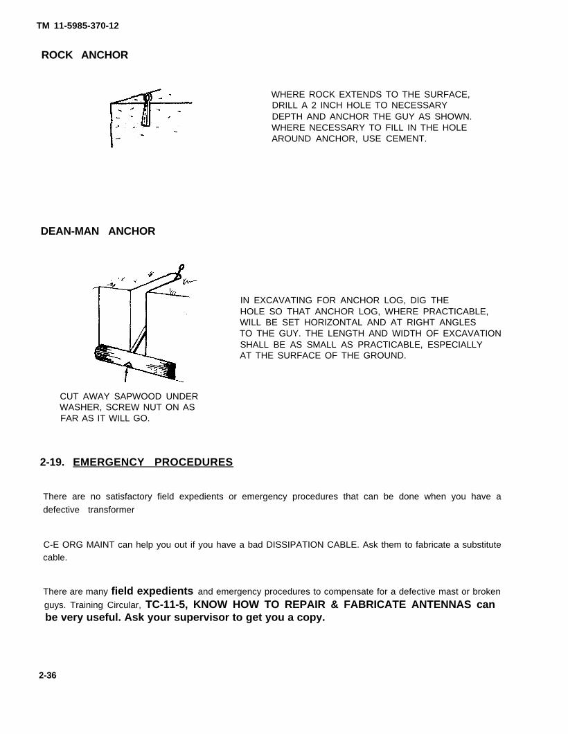
ROCK ANCHOR
WHERE ROCK EXTENDS TO THE SURFACE,DRILL A 2 INCH HOLE TO NECESSARYDEPTH AND ANCHOR THE GUY AS SHOWN.WHERE NECESSARY TO FILL IN THE HOLEAROUND ANCHOR, USE CEMENT.
DEAN-MAN ANCHOR
IN EXCAVATING FOR ANCHOR LOG, DIG THEHOLE SO THAT ANCHOR LOG, WHERE PRACTICABLE,WILL BE SET HORIZONTAL AND AT RIGHT ANGLESTO THE GUY. THE LENGTH AND WIDTH OF EXCAVATIONSHALL BE AS SMALL AS PRACTICABLE, ESPECIALLYAT THE SURFACE OF THE GROUND.
CUT AWAY SAPWOOD UNDERWASHER, SCREW NUT ON ASFAR AS IT WILL GO.
2-19. EMERGENCY PROCEDURES
There are no satisfactory field expedients or emergency procedures that can be done when you have a
defective transformer
C-E ORG MAINT can help you out if you have a bad DISSIPATION CABLE. Ask them to fabricate a substitutecable.
There are many field expedients and emergency procedures to compensate for a defective mast or broken
guys. Training Circular, TC-11-5, KNOW HOW TO REPAIR & FABRICATE ANTENNAS canbe very useful. Ask your supervisor to get you a copy.
2-36

TM 11-5985-370-12
CHAPTER 3
OPERATOR/CREW MAINTENANCE
SECTION I. TROUBLESHOOTING PROCEDURES
3-1. TROUBLESHOOTING GUIDELINES
The simple and rugged construction of ANTENNA GROUP OE-303/GRC reduces troubleshooting andmaintenance procedures.
The following table covers the troubleshooting steps you should take if there is a communications failure. If
your trouble cannot be corrected, notify C-E ORG MAINTENANCE.
The table does not cover troubleshooting the radio set. Before troubleshooting the antenna, make sure thatthe radio is not the cause of the trouble by using the radio set troubleshooting guidance in the Radio SetTechnical Manual.
TABLE 3-1. TROUBLESHOOTING
TROUBLE
Test or Inspection
. Corrective Action
COMMUNICATIONS CANNOT BE ESTABLISHED WITH THE DISTANT STATION
STEP 1
Double check the magnetic azimuth heading of the HALF-RHOMBIC ANTENNA.
Reorient the HALF—RHOMBIC ANTENNA if it is not properly oriented.STEP 2
Carefully check all antenna components and connections starting at the radio set.
Tighten loose connections and replace defective cables and/or components.
Report any transformer too hot to touch or damaged receptacles to
C-E ORG MAINTENANCE.STEP 3
Check TRANSFORMER hookup.
Reconnect the TRANSFORMERS so that the TERMINATION TRANSFORMER
is at the antenna end pointing towards the distant station.
3-1

TM 11-5985-370-12
SECTION II. OPERATOR/CREW MAINTENANCE PROCEDURES
3-2. Cleaning
Clean components with CLEAR WATER and clean rags. DO NOT USE SOLVENTS ON THETRANSFORMERS.
Clean coaxial cable fittings with a small stiff brush. If a solvent must be used, useTRICHLOROTRIFLOUROETHANE and OBSERVE THE FOLLOWING WARNING.
FUMES OF TRICHLOROTRIFLOUROETHANE ARE POISONOUS. PROVIDEADEQUATE VENTILATION WHENEVER YOU USE IT. DO NOT USE THlSSOLVENT NEAR HEAT OR OPEN FLAME. TRICHLOROTRIFLOUROETHANEWILL NOT BURN, BUT HEAT TURNS THE SOLVENT INTO POISONOUSAND IRRITATING FUMES. DO NOT BREATHE THE FUMES OR VAPORS.THIS SOLVENT DISSOLVES NATURAL SKIN OILS. DO NOT GET THESOLVENT ON YOUR SKIN. USE GLOVES, SLEEVES AND AN APRONWHICH THE SOLVENT CANNOT PENETRATE. IF THE SOLVENT IS TAKENINTERNALLY, CONSULT A PHYSICIAN IMMEDIATELY. USE THIS SOLVENTONLY ON THE METAL MAST SECTIONS, DO NOT CLEAN THE TRAN-SFORMER HOUSINGS WITH THIS SOLVENT.
3-3. MOISTUREPROOFING COAXIAL CONNECTORS
If your antenna installation is to stay up several months, it is desirable to moistureproof the coaxial cable
connectors.
First clean the area on the outside of the connectors (5 to 6 inches).
With the coaxial cable connected, apply several layers of electrical tape.
3-2

TM 11-5985-370-12
CHAPTER 4
ORGANIZATIONAL MAINTENANCE
SECTION I. REPAIR PARTS, SPECIAL TOOLS, TMDE ANDSUPPORT EQUIPMENT
4-1. COMMON TOOLS
For authorized common tools and equipment, refer to the Modified Table of Organization and Equipment(MTOE) applicable to your unit.
4-2. TMDE, SPECIAL TOOLS AND SUPPORT EQUIPMENT
Refer to the Maintenance Allocation Chart (MAC), Appendix B in the back of this manual.
4-3. REPAIR PARTS
Refer to: TM 11-5985-370-20P, Organizational Repair Parts and Special Tools Lists for Antenna GroupOE-303/GRC.
SECTION Il. ORGANIZATIONAL PMCS
4-4. GENERAL
To be sure that your equipment is always ready for your mission, you must do scheduled PMCS as outlined inTable 4-1.
Organizational Maintenance PMCSS are scheduled monthly and quarterly.
Use the ITEM NO. in your PMCS table to get the numbers for the TM ITEM NO. column on DA Form 2404(Equipment Inspection and Maintenance Worksheet) when you fill out the form.
4-1

Appendix C-1.
TM 11-5985-370-12
TABLE 2-1. ORGANIZATIONAL PREVENTIVE MAINTENANCE CHECKS AND SERVICES
M = MONTHLY Q = QUARTERLY
4-2
TM 11-5985-370-12
Section Ill. TROUBLESHOOTING
4-5. TROUBLESHOOTING GUIDLINES
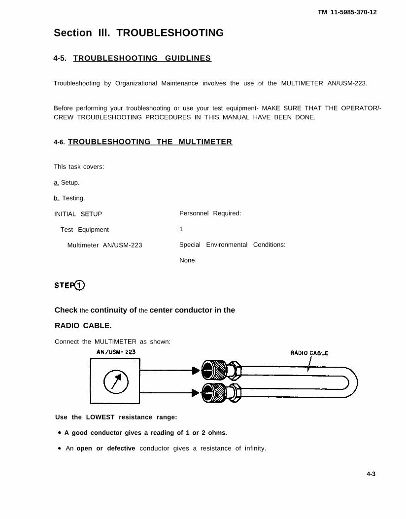
Troubleshooting by Organizational Maintenance involves the use of the MULTIMETER AN/USM-223.
Before performing your troubleshooting or use your test equipment- MAKE SURE THAT THE OPERATOR/-CREW TROUBLESHOOTING PROCEDURES IN THIS MANUAL HAVE BEEN DONE.
4-6. TROUBLESHOOTING THE MULTIMETER
This task covers:
a. Setup.
b. Testing.
INITIAL SETUP Personnel Required:
Test Equipment 1
Multimeter AN/USM-223 Special Environmental Conditions:
None.
Check the continuity of the center conductor in the
RADIO CABLE.
Connect the MULTIMETER as shown:
Use the LOWEST resistance range:
A good conductor gives a reading of 1 or 2 ohms.
An open or defective conductor gives a resistance of infinity.
4-3

TM 11-5985-370-12
Check for leakage or short between the center conductor and the shield in the RADIO CABLE.
AND
Repeat this test on the DISSIPATION CABLE.
Connect the MULTI METER as shown below:
Use the HIGHEST resistance range.
A good cable will give a reading of infinity.
A defective cable will give a reading of some continuity.
Check for an open braid or shield in the RADIO CABLE,
AND
REPEAT this test on the DISSIPATION CABLE.
Connect the MULTIMETER as shown:
Use the LOWEST resistance range.
A good braid or shield gives a reading of 1 or 2 ohms.
An open or defective braid gives a high resistance reading (or even infinity).
4-4

TM 11-5985-370-12
Check the resistance of each transformer.
Connect the multimeter as shown:
Use the LOWEST resistance range.
A good transformer should give a reading of less than 1 OHM. This indicates normal continuity.
NOTEEven though the resistance check indicates normal continuity, this is noguarantee that the transformer will operate properly with radio frequencies. Thebest check of a transformer is in an operating hookup.
A reading of MORE THAN 1 OHM on the lowest scale
ORa reading of INFINITY ON ANY SCALEINDICATES TRANSFORMER PROBLEMS.
4-5

TM 11-5985-370-12
SECTION IV. ORGANIZATIONAL MAINTENANCE PROCEDURES
4-7. SCOPE OF ORGANIZATIONAL MAINTENANCE
Organizational Maintenance personnel should be familiar with:
Operator/Crew operating and maintenance procedures for the radio equipment connected to theHALF-RHOMBIC ANTENNA.
Operator/Crew operating and maintenance procedures for the HALF-RHOMBIC ANTENNA.
PMCS and troubleshooting procedures by Organizational Maintenance have been covered in previousparagraphs.
Parts replacement is covered in the following paragraph.
4.8. REPLACEMENT PARTS
See the TM 11-5985-370-20P for authorized replacement parts.
4-6

TM 11-5985-370-12
APPENDIX AREFERENCES
A-1. SCOPE
This appendix lists forms, field manuals, technical manuals and miscellaneous publications referenced in
this manual,
A-2. FORMS
DA Form 2028 Recommended Changes to Publications and Blank Forms.
DA Form 2028-2 Recommended Changes to Equipment Technical Publications.SF 361 Discrepancy in Shipment Report (DISREP)SF 368 Quality Deficiency Report.
A-3. FIELD MANUALS
FM 21-11 Artificial RespirationFM 21-26 Map Reading
A-4. TECHNICAL MANUALS
TM 11-5820-398-12
TM 11-5820-401-10-1
TM 11-5820-401-10-2
TM 11-5820-401-20-1
TM 11-5820-401-20-2
Operator’s and Organizational Maintenance Manual Including Repair Parts andSpecial Tools List: Radio Set AN/PRC-25 (Including Receiver-Transmitter, RadioRT-505/PRC-25).
Operator’s Manual: Radio Sets AN/VRC-12 (NSN 5820-00-223-7412), AN/VRC-43(5820-00-223-7415), AN/VRC-44 (5820-00-223-7471), AN/VRC-45 (5820-00-223-7418), AN/VRC-46 (5820-00-223-7533), AN/VRC-47 (5820-00-223-7434), AN/VRC-48 (5820-00-223-7435) and AN/VRC-49 (5820-00-223-7437) Used With an IntercomSystem).
Operator’s Manual: Radio Sets AN/VRC-12 (NSN 5820-00-223-7412), AN/VRC-43(5820-00-223-7415), AN/VRC-44 (5820-00-223-7417), AN/VRC-45 (5820-00-223-7418), AN/VRC-46 (5820-00-223-7433) , AN/VRC-47 (5820-00-223-7434) , AN/VRC-48 (5820-00-223-7435) and AN/VRC-49 (5820-00-223-7437) Used With an IntercomSystem).
TM 11-5820-401-20-1, Organizational Maintenance Manual: RADIO SETS: AN/VRC-12 (NSN 5820-00-223-7412), AN/VRC-43 (NSN 5820-00-223-7415), AN/VRC-44 (NSN5820-00-223-7417), AN/VRC-45 (NSN 5800-00-223-7418), AN/VRC-46 (NSN 5820-00-223-7434), AN/VRC-48 (NSN 5820-00-223-7435), AN/VRC-49 (NSN 5820-00-223-7437) (Used without intercom set)
TM 11-5820-401-20-2, Organizational Maintenance Manual: RADIO SETS: AN/VRC-12 (NSN 5820-00-223-7412), AN/VRC-43 (NSN 5820-00-223-7415), AN/VRC-44 (NSN5820-00-223-7417), AN/VRC-45 (NSN 5820-00-223-7418), AN/VRC-46 (NSN 5820-00-223-7433), AN/VRC-47 (NSN 5820-00-223-7434, AN/VRC-48 (NSN 5820-00-223-7435), AN/VRC-49 (NSN 5820-00-223-7437) (Used with intercom set AN/VIC-1 (V))
A-1

TM 11-5985-370-12
TM 11-5820-498-12 Operator’s and Organizational Maintenance Manual: Radio Sets AN/VRC-53 (NSN5820-00-223-7467), AN/VRC-64, (NSN 5820-00-223-7475), AN/GRC-125 (NSN 5820-00-223-7411), and AN/GRC-125 5820-00-223-7411), and AN/GRC-160 (NSN 5820-00-223-7473), and Amplifier-Power Supply Groups OA-3633/GRC and OA-3633A/-GRC (NSN 5820-00-973-3333).
TM 11-5820-667-12 Operator’s and Organizational Maintenance Manual (Including Repair Parts List):Radio Set AN/PRC-77 (NSN 5820-00-930-3724) (Including Receiver-Transmitter,
Radio RT-841/PRC-77 (NSN 5820-00-930-3725)).
TM 11 5985-370-12-HR Hand Receipt Covering Contents of Components of End Item (COEI) Basic Issue
TM 11-5985-370-20P
TM 11-6625-654-14
Items, (Bll), and Additional Authorization List (AAL) for Antenna Group OE-
303/GRC (NSN) 5985-01-152-5845)
Organizational Repair Parts and Special Tools Lists For Antenna Group
OE-303/GRC.
Operator’s Organizational, Direct Support, and General Support Maintenance
Repair Parts and Special Tools List (Including Depot Maintenance Repair Parts andSpecial Tools List) for Multimeter AN/USM-223.
A-5. MISCELLANEOUS PUBLICATIONS
AMDF (AR708-1) IAW Packaging Segment of AMDF by NSN.
AR 735-11-2 Reporting of Item and Packaginq Discrepancies.
AR 750-244-2 Destruction of Army Materiel.
DA PAM 310-1 Consolidated Index of Army Publications and Blank Forms.
0A PAM 738-750 The Army Maintenance-Management System (TAMMS).
SB 11-573 Painting and Preserving of Supplies Available for Field Use for Electronics CommandEquipment.
SB 11-614 Caution Notice for Antenna Bases, Towers, and Other Mast Structures.TB 43-0018 Field Instructions for Painting and Preserving Electronics Command Equipment
Including Camouflage Pattern Painting of Electrical Equipment Shelters.TB SIG 291 Safety Measures to be Observed When Installing and Using Whip Antennas. Field
Type Masts, Towers, Antennas, and Metal Poles That Are Used with Communication,Radar, and Direction Finder Equipment.
A-2

TM 11-5985-370-12
APPENDIX BMAINTENANCE ALLOCATION
Section I. INTRODUCTIONB-1. GeneralThis appendix provides a summary of the maintenance operations for Antenna Group OE-303/GRC. Itauthorizes categories of maintenance for specific maintenance functions on repairable items andcomponents and the tools and equipment required to perform each function. This appendix may beused as an aid in planning maintenance operations.
B-2. Maintenance Function.Maintenance functions will be limited to and defined as follows:
a. Inspect. To determine the serviceability of an idea by comparing its physical, mechanical, and/orelectrical characteristics with established standards through examination.
b. Test. To verify serviceability and to detect incipient failure by measuring the mechanical orelectrical characteristics of an item and comparing those characteristics with prescribed standards.
c. Service. Operations required periodically to keep an item in proper operating condition, i.e., toclean (decontaminate), to preserve, to drain, to paint, or to replenish fuel, lubricants, hydraulic fluids,or compressed air supplies.
d. Adjust. To maintain, within prescribed limits, by bringing into proper or exact position, or bysetting the operating characteristics to the specified parameters.
e. Aline. To adjust specified variable elements of an item to bring about optimum or desiredperformance.
f. Calibrate. To determine and cause corrections to be made or to be adjusted on instruments or testmeasuring and diagnostic equipments used in precision measurement. Consists of comparisons oftwo instruments, one of which is a certified standard of known accuracy, to detect and adjust anydiscrepancy in the accuracy of the instrument being compared.
g. Install. The act of emplacing, seating, or fixing into position an item, part, module (component orassembly) in a manner to allow the proper functioning of the equipment or system.
h. Replace. The act of substituting a serviceable like type part, subassembly, or module (componentor assembly) for the unserviceable counterpart.
i. Repair. The application of maintenance services (inspect, test, service, adjust, align, calibrate,replace) or other maintenance actions (welding, grinding, riveting, straightening, facing, remachining,or resurfacing) to restore serviceability to an item by correcting specific damage, fault, malfunction,or failure in a part, subassembly, module (component or assembly), end item, or system.
j. Overhaul. That maintenance effort (service/action) necessary to restore an item to a completelyserviceable/operational condition as prescribed by maintenance standards (i.e., DMWR) in appropri-ate technical publications. Overhaul is normally the highest degree of maintenance performed by theArmy. Overhaul does not normally return an item to like new condition.
k. Rebuild. Consists of those services/actions necessary for the restoration of unserviceableequipment to a like new condition in accordance with original manufacturing standards. Rebuild isthe highest degree of material maintenance applied to Army equipment. The rebuild operationincludes the act of returning to zero those age measurements (hours, miles, etc.) considered inclassifying Army equipments/components.
B-1

TM 11-5985-370-12
B-3. Column Entries.a. Column 1, Group Number. Column 1 lists group numbers, the purpose of which
components, assemblies, subassemblies, and modules with the next higher assembly.is to identify
b. Column 2, Component Assembly. Column 2 contains the noun names of components,assemblies, subassemblies, and modules for which maintenance is authorized.
c. Column 3, Maintenance Functions. Column 3 lists the functions to be performed on the item listedin column 2. When items are listed without maintenance functions, it is solely for purpose of having thegroup numbers in the MAC and RPSTL coincide.
d. Column 4, Maintenance Category. Column 4 specifies, by the listing of a “work time” figure in theappropriate subcolumn(s), the lowest level of maintenance authorized to perform the function listedin column 3. This figure represents the active time required to perform that maintenance function atthe indicated category of maintenance. If the number or complexity of the tasks within the listedmaintenance function vary at different maintenance categories, appropriate “work time” figures willbe shown for each category. The number of task-hours specified by the “work time” figure representsthe average time required to restore an item (assembly, subassembly, component, module, end itemor system) to a serviceable condition under typical field operating conditions. This time includespreparation time, troubleshooting time, and quality assurance/quality control time in addition to thetime required to perform the specific tasks identified for the maintenance functions authorized in themaintenance allocation chart. Subcolumns of column 4 are as follows:
C - Operator/CrewO - OrganizationalF - Direct SupportH - General SupportD - Depot
e. Column 5, Tools and Equipment. Column 5 specifies by code, those common tool sets (notindividual tools) and special tools, test, and support equipment required to perform the designatedfunction.
f. Column 6, Remarks. Column 6 contains an alphabetic code which leads to the remark in sectionIV, Remarks, which is pertinent to the item opposite the particular code.
B-4. TOOL and Test Equipment Requirements (Sect. Ill).a. Tool or Test Equipment Reference Code. The numbers in this column coincide with the numbers
used in the tools and equipment column of the MAC. The numbers indicate the applicable tool or testequipment for the maintenance functions.
b. Maintenance Category. The codes in this column indicate the maintenance category allocatedthe tool or test equipment.
c. Nomenclature. This column lists the noun name and nomenclature of the tools and testequipment required to perform the maintenance functions.
d. National/NATO Stock Number. This column lists the National/NATO stock number of thespecific tool or test equipment.
e. Tool Number. This column lists the manufacturer’s part number of the tool followed by theFederal Supply Code for manufacturers (5-digit) in parentheses.
B-5. Remarks (Sect. IV).a. Reference Code. This code refers to the appropriate item in section II, column 6.b. Remarks. This column provides the required explanatory information necessary to clarify items
appearing in section Il.
B-2

TM 11-5985-370-12
SECTION II MAINTENANCE ALLOCATION CHARTF O R
ANTENNA GROUP OE-303/GRC
B-3

TM 11-5985-370-12
S E C T I O N I I I T O O L A N D T E S T E Q U I P M E N T R E Q U I R E M E N T S
F O R
ANTENNA GROUP OE-303/GRC
B-4

TM 11-5985-370-12
S E C T I O N I V . R E M A R K S
A N T E N N A G R O U P O E - 3 0 3 / G R C
B-5

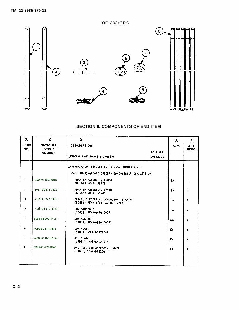
APPENDIX CCOMPONENTS OF END ITEM
AND BASIC ISSUE ITEMS LIST
TM 11-5985-370-12
Section I. INTRODUCTIONC-1. ScopeThis appendix lists components of end item and basic issue items for Antenna Group OE-303/GRC tohelp you inventory items required for safe and efficient operation.
C-2. GeneralThe components of End Item and Basic Issue Items Lists are divided into the following sections:
a. Section II — Components of End Item. This listing is for information purposes only, and is notauthority to requisition replacements. These items are part of the end item, but are removed andseparately packaged for transportation or shipment. As part of the end item, these items must be withthe end item whenever it is issued or transferred between property accounts. Illustrations arefurnished to assist you in identifying the items.
b. Section Ill — Basic Issue Items. These are the minimum essential items required to place theAntenna Group OE-303/GRC in operation, to operate it, and to perform emergency repairs. Althoughshipped separately packaged, Bll must be with the Antenna Group OE-303/GRC during operationand whenever it is transferred between property accounts. The illustrations will assist you withhard-to-identify items. This manual is your authority to request/requisition replacement Bll, based onTOE/MTOE authorization of the end item.
C-3. Explanation of ColumnsThe following provides an explanation of columns found in the tabular listings:
a. Column (1) — Illustration Number (Illus Number). This column indicates the number of theillustration in which the item is shown.
b. Column (2) – National Stock Number. Indicates the National stock number assigned to the item.The National stock numbers in section Ill will be used for requisitioning basic issue items.
c. Column (3) — Description. Indicates the National item name and, if required, a minimumdescription to identify and locate the item. The last line for each item indicates the FSCM (inparentheses) followed by the part number.
d. Column (4) – Unit of Measure (U/M). Indicates the measure used in performing the actualoperational/maintenance function. This measure is expressed by a two-character alphabeticalabbreviation (e.g., ea, in, pr).
e. Column (5) — Quantity required (Qty Rqd). Indicates the quantity of the item authorized to be usedwith/on the equipment.
C-1
TM 11-8985-370-12
OE-303/GRC
SECTION II. COMPONENTS OF END ITEM
C-2

TM 11-5985-370-12
O E - 3 0 3 / G R C
SECTION II. COMPONENTS OF END ITEM
C-3

TM 11-5985-370-12
SECTION II. COMPONENTS OF END ITEM
C - 4

TM 11-5985-370-12
SECTION III. BASIC ISSUE ITEMS
C-5

TM 11-5985-370-12
OE-303/GRC
SECTION III. BASIC ISSUE ITEMS
C - 6

TM 11-5985-370-12
APPENDIX EEXPENDABLE SUPPLIES AND MATERIALS LIST
Section I. INTRODUCTIONE-1 ScopeThis appendix lists expendable supplies and materials you will need to operate and maintain AntennaGroup OE-303/GRC. These items are authorized to you by CTA 50-970. Expendable Items (ExceptMedical, Class V, Repair Parts, or Heraldic Items).
E-2. Explanation of Columnsa. Column 1 — Item Number. This number is assigned to the entry in the listing and is referenced in
the narrative instructions to identify the material) e.g., “Use cleaning compound, item 5, App. D“).b. Column 2— Level. This column identifies the lowest level of maintenance that requires the listed
item.C — Operator/CrewO — Organizational MaintenanceF — Direct Support MaintenanceH — General Support Maintenance
c. Column 3 — National Stock Number. This is the National stock number assigned to the item; use itto request or requisition the item.
d. Column 4 — Description. Indicates the Federal item name and, if required, a description to”identify the item. The last Iine for each item indicates the part number followed by the Federal SupplyCode for Manufacturer (FSCM) in parentheses, if applicable.
e. Column 5 — Unit of Measure (U/M). Indicates the measure used in performing the actualmaintenance function. This measure is expressed by a two-character alphabetical abbreviation (e.g.,ea, in, pr). If the unit of measure differs from the unit of issue, requisition the lowest unit of issue thatwill satisfy your requirements,
E-1

TM 11-5985-370-12
S E C T I O N I I E X P E N D A B L E S U P P L I E S A N D M A T E R I A L S L I S T
E-S


By Order of the Secretary of the Army:
Official:
ROBERT M. JOYCEMajor General, United States Army
The Adjutant General
Distribution:
To be distributed in accordance with special list.
JOHN A. WICKHAM JR.General, United States Army
Chief of Staff
U . S . G O V E R N M E N T P R I N T I N G O F F I C E : 1 9 8 9 - 2 4 2 - 4 5 1 ( 1 5 5 2 )

PIN: 056124-000


![homescience10.ac.inhomescience10.ac.in/storage/results/July2019/...R [GRC & R [GRC & TSC] 448 422 372 36 R [GRC & 390 411 R [GRC] 399 R [TSC] R [TSC] ...](https://static.documents.pub/doc/80x56/6124d44c63d24709ac3c7280/-r-grc-r-grc-tsc-448-422-372-36-r-grc-390-411-r-grc-399.jpg)

