t t L TECHNICAL NOTE No. 1’777 DIRECT-READING DESIGN CHARTS FOR 24S-T ALUMINUM-ALLOY FLAT COMPRJ3SSION PANELS HAVING LONGITUDINAL STRAIGHT-WEB Y-SECTION STIFFENERS By Norris F. Dow, Ralph E. Hubka, and William M. Roberts Langley Aeronautical Laboratory Langley Field, Va. .! ...... ———— .. .-—... .. . . ..—7 ., Washington January 1949 -----..= .. --- 1... -. . .. .. . .. —.=. . - .. -—... . .... . . 1 .—..— I I I I 1 [ I 1 I I t I J ,, .,
Transcript
t
t
LTECHNICAL NOTE
No. 1’777
DIRECT-READING DESIGN CHARTS FOR 24S-T ALUMINUM-ALLOY
FLAT COMPRJ3SSION PANELS HAVING LONGITUDINAL
STRAIGHT-WEB Y-SECTION STIFFENERS
By Norris F. Dow, Ralph E. Hubka, and William M. Roberts
By Norris l?.Dow, Ralph E. Hubka, and William M. Roberts
Direct+ead@ design charts axe presented for 2k’?#Zalumin~oyflat ccmqwessicm panels ha- longitudinal straightweb Y-sectimstiffeners. These c~s make possible the Uect determination of thestress and all the panel propofiions required to carry a gimn intensityof loading tith a givm skin thickness and effective length of psnel.
mTRODucTmN
Design charts for wing coqmession panels have been presented inseveral difYerent forms. (See references 1 and 2.) In reference 3, aform was developed which permitted the direct selection of propotiionsfor given values of the principal design conditions – intensity ofloading, skin thiclmess, and effective length of panel. This form alsomade possible the ready determination of the proportions having minimmweight to meet these ccmditicms. The charts presented in reference 3covered ~ al.umin~oy flat compression panel.ehaving longitudhslstraight=webY~ectian stiffeners. similar charts for 24S+ smminw+alloy panels with formed Z%ecticm stiffeners are presented h reference 4and direct-reading design charts for 24SJI almdmm+dl OY Y-stiffenedpanels me presmted herein.
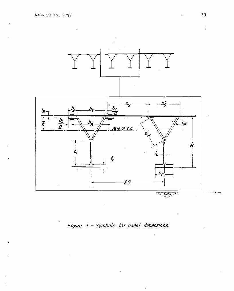
SYMBOIS
The symbols used for the panel dimensions areb addition, the following symbols are used:
‘i compressive load ~er inch of penel width, kips per inch
r W fillet radii, hches
z. cros~ectional area per”inch of panel width, expressed as anequivalent or average thickness, inches
P radius of ~tion, iuches
F.f average stress at fai13ng
‘cr stress for local bucld.lng
%y compressive
Direc+reading
yield stress,
load, ksi
of sheet, ksi
ksi
r
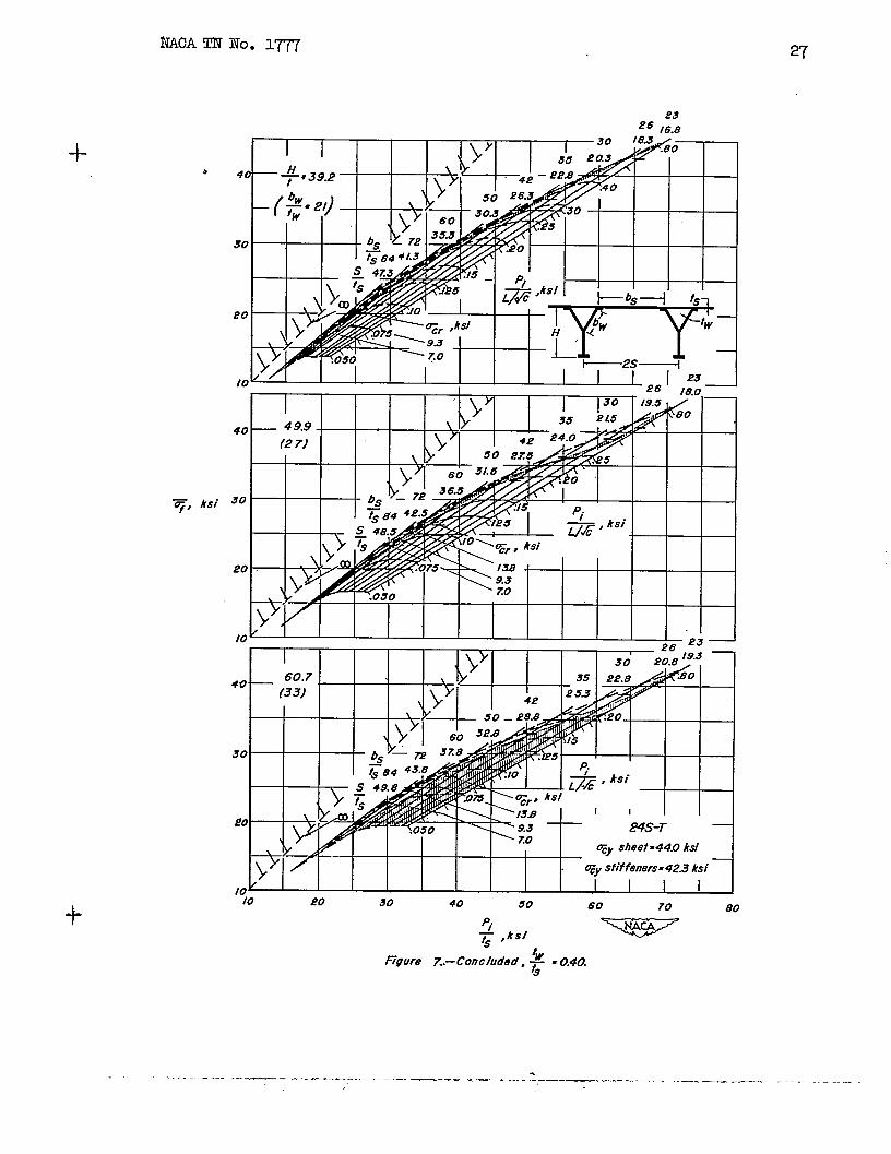
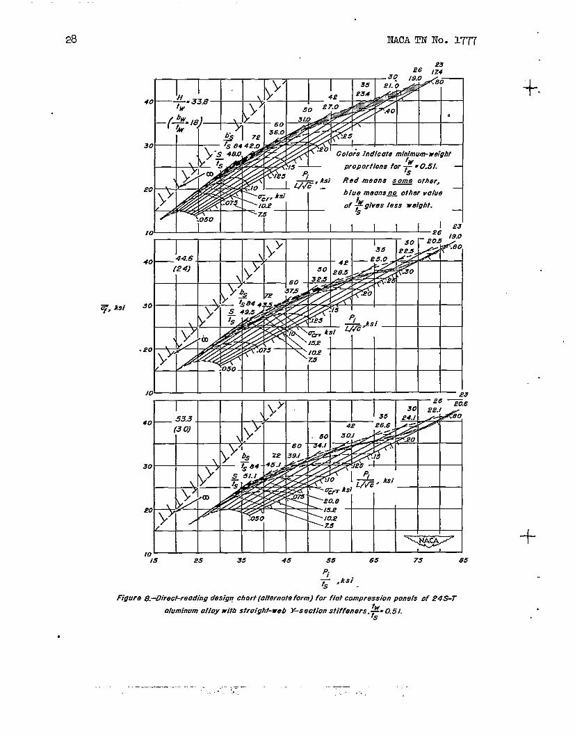
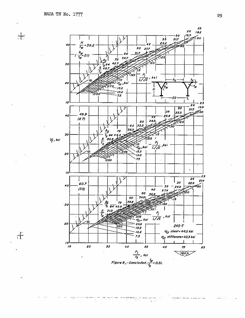
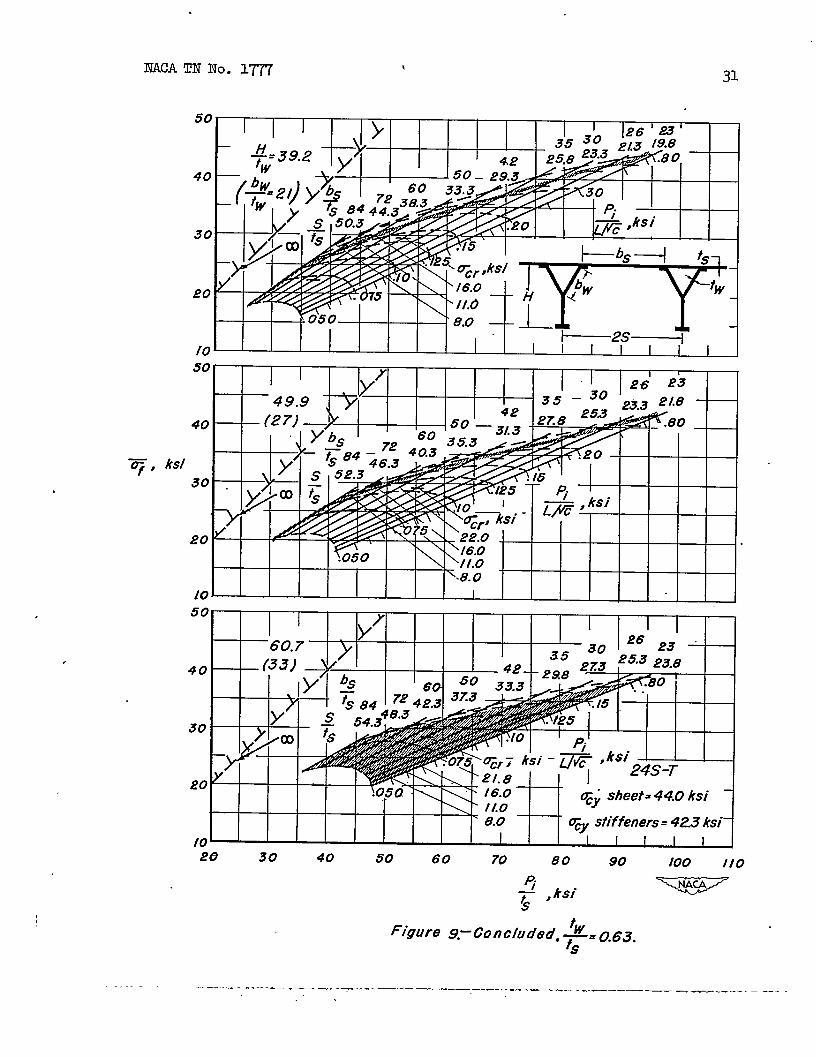
D~IKGDE31GN CHARTS
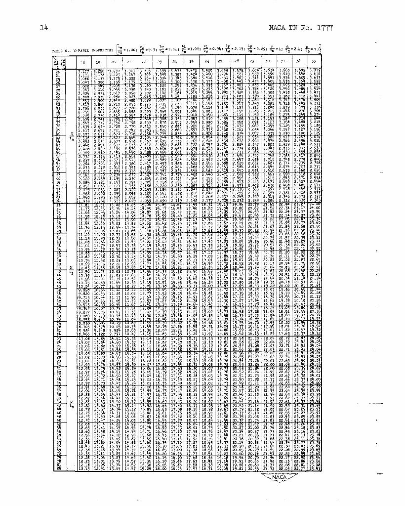
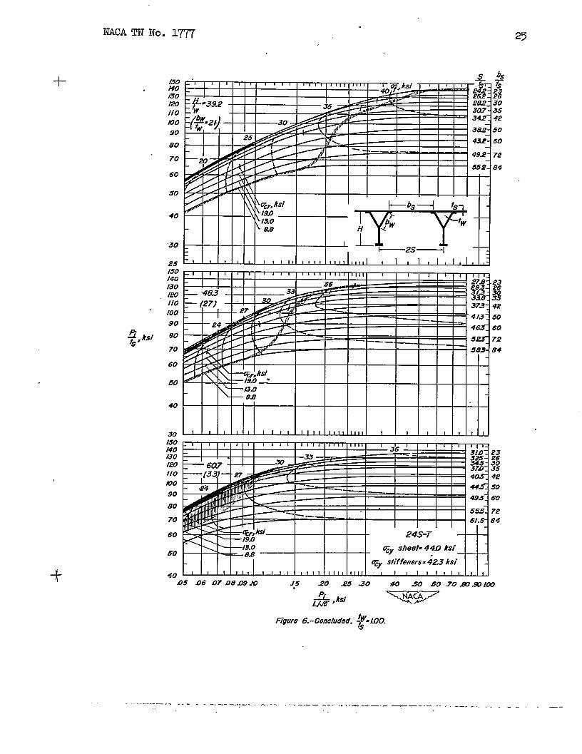
design charts for 2- alumin~oy flat cmpression penels wti% lcn@tud3nal straight-webY-section ‘&.ffenershaving the popetiies and ~oportions given h tables 1 to 6 me pre-sented h two form in figures 2 to U.. w the first form (figs. 2 to 6),the desi~ cmditicms of intensity of loading, effective lenghh ofpsnel, end skin.thiclmess are inmrpcrated in the ordinate Pi/t~ and.
the abscissa a. This form, having the desi~ cmditims incorporatedL/J’6
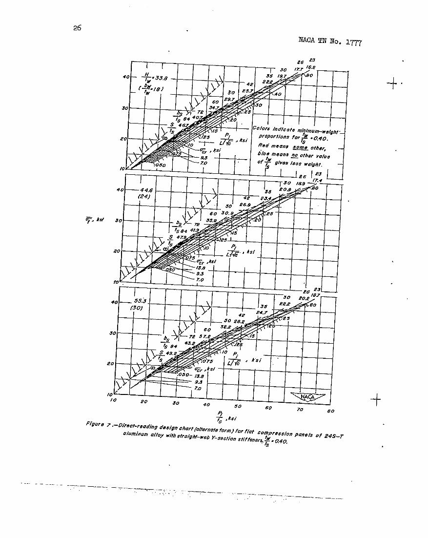
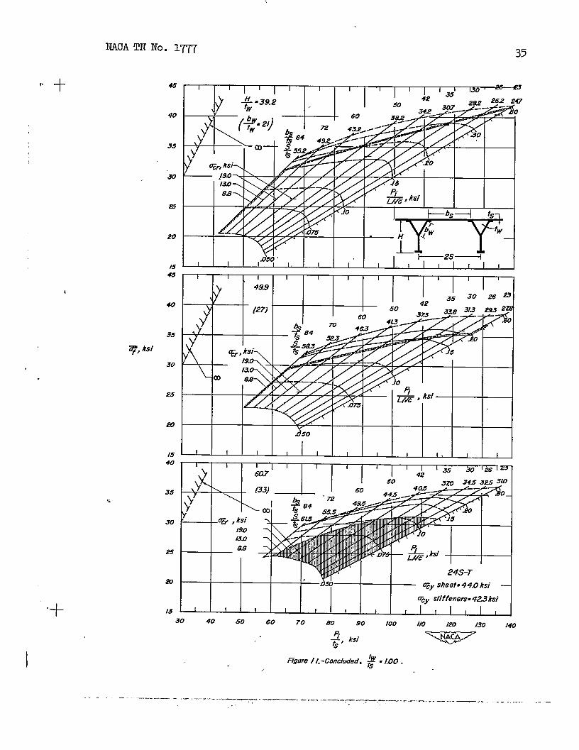
h the ordinate and abscissa, is the more useful for most desi~ purposesbecause the curves are more widely spaced @ titerpol.ationis morestrai@forward . Ih the second (alternate)form (figs. 7 to IL), theaverage stress at failure ~ is plotted against Pi/tS as was dme tn
the eummexy plots of reference 5. T!hia alternate form, hamlng the stress –an inverse measure of weight for a @van load – as ord3nate, is the moreuseful for InaMng generalizations and.comparisms of structural efficiency fbecause it shows how nearly the stress actually carried approaches theupper limit corresponding to the stress &t would be achieved by a pureshell construction if a pure shell could carry the load without f+ure.
This upper limit of stress is represented by the Unes for ~f = “~ts
(infinite stiffener spacing) in figures 7 to Il.
Values of the ratios of stiffener thickhess to sti thiclmess ~/tS,
average spacing of rivet lines to skin thickness S/tS (because there
are two rivet lines associated with each Y-section, the sttf’fenerspacingeqwils 2S), md height of Wfiener to stfi=er ~c~ss H/~, which
will satisfy the design ccm33tiom, may be found &Jrect3y from thesecharts, end the corresponding section properties t/ts, 11/t& - P/%
may be found frcm tables 2 to 6. = the first form of desi@ chart
(figs. 2 to 6) dashed lines are used to iniicate tiues of average
u
*
.. _ .—. , . -=7 —= —. ... .=.
,-. —..
..—. — -..
.. :..-! ,,. , ..’
NACATN NO. 1~
stress at fallure 3f;
(figs. 7 to u) dashed
whereas, m the alternate form of
lines are used to indicate values
both forms the value of Ff correspcmiing to the point at which each
desi chart5?of J. ~L/fi
curve is cut by a short he~~ lihe is the value of the stress for localbuckl~ UCr for the propotiicms represented by the curve. For
example, the value of Ucr for ~. 33.8 and ~ .16.2 in figure 2
(
% t~
is ap~oximately 41.3 ksi. Qnly a very *ort panel
would buckle before failure –mehavinga valueof
of these proportions
.3
line would fallE the value of ucr is so low that the short heavy
outside the boundaries of the chart, a numerical value of Ucr is given -end is associated with the.proper proportions by a leader to the curve.The panel proportim which have mhxlmum weight are indicated on bothforms of these charts by the use of colors as follows:
(1) H the Proportions correspond to a blue region, they are the~oportims which give the lightest possible 24S4 Y-stiffened pauelwhich wIU meet the desi~ conditims
(2) IX the proportions correspcmd to a red regim, they are theli@test possible at the ratio of stiffener thickness to sldn thicknessgiven by that particular chart, but mm other thiclmess ratio wouldgiVe a lighter defligu
(3) m me proportionsmeet the design conditim,meet the ccm33tiaus
cmrespmd to a white regim,but they are not the lightesb
the proportimswhich will
.
Because h many cases the proportions may be varied somewhat frmthose indicated by the red end blue regims with little change in the
. value of the stress that can be carried, too mch importance should notbe attached to the exact proportions indicated by the colors to havemintmm weight. In any particular case for which a detiatim frmu themh3mm+eight yroportims is made, however, cautim dictates that the’weight penalty associated with this deviation be detemdned.
The direct+reading design charts presented herein were developed inthe manner described in reference 3 from the test data end resultingcurves given in reference 5.
USE OF TEED EQQHIMDING DlE5KN CHARTS
The manner of using the d.irect+readingdesign charts depends insome measure on the desired degree of ~ecision of interpolation smongthe curves. For mmy purposes, interpolationby inspection is ofadequate acmrac y, and the use of the charts requires only the calculation
Piof the values of the desi~ parameters PJt~ em — to permit the
L/fidesired proporticms to be read directly from the curv88. The proportionsfor nd3Mmm wei*t, moremer, may be found directly as those comespcmdingto the blue regim on the curves. .
If more accurate interpolation is desired, a plot can readily beme of H/~, =f, m acr aga= s/ts at the given v-dues of pi/tS
‘i— end the proporticms can be picked from it. (This plot IsL/c
similar to that which results from the use of the ~“ifjht desi~procedure with the previously available design charts as illustrated inreference 2.) On a plot of this type, the proportions for minimum weightcorrespond to those associated with the highest value of Zf.
As a check cm the accuracy of interpolation,the cross-sectional areaper inch of tidth of the design may be detemined from the values of z/t~given h tables 2 to 6 and the value of the intensity of loading Pi that
can be carried on this cros~ectimal area per inch at the value of Zf
given by the charts may then be compared with the design value of Pi.
In order to illustrate the use of the Urect-reading desigq chartsend the shqlicity of the cmputaticms associated with them, a psnelwill be desi~d for mintmzm weight to meet the ssme principal designconditions used.to illustrate the desiga procedures ~ reference 2,name~ :
1. Tntensity of loading Pi = 3.0 kips per inch
2. Skin thiCkIleSS ts = O.O@+inch
3. Effective length L/@ = 20 inches
As was pointed out in reference 5, an intensity of loadhg as smaUas 3.0 kips per inch may require a stiffener thiclmess smaller thancan be successfully extruded. The value of Pi of 3.0 kips ~er inchis retahed for the exsmple, however, in order to provide a readyccqmrison with the examples of reference 2.
Tn order to illustrate the use of the d&ec~eaiUng design chartswhen more accuracy than that corresp
Yto interpolation by *ection
is desired, a ylot has teen made (fig. 12 of the values of Zif,crcr,
Pi
end H/~ given by the chextm at the design values of l?i/tS “and —.L/fi
The proportions which give the highest value of q can be readily -
selected from a plot of this kind. (For the example “theseproportionsare so nearly the same as were obtained by inspection that the valueswill not be repeated; however, the flatness of the curv&’of Ff against
S/tS in figure 12 shows that, for a fairly @de range of propotiions
for this particular desi~, the stress that could be carried would besubstantially the same as that for mimhmm weight.)
As a check on the accuracy of interpolatim, the magnitude of %/tS
for these proportions can be detemined frcm table 2 and multiplied bythe values of ts and ~ for the desi~. This productequal to the desigu value of l?i. For the exem@le
zf= 31.3 ksi
-t— = 1.500‘s
should be
= 3.3(1.500)(0.064)
= 3.0 kips per inch
which agrees with the design value of Pi originally assumed.
-w Aer-utfcd LabOratO~Naticmal Advisq Committee for Aeronautics
4. Dow, ~OIU’iSy., emd Keevil, Albert S., Jr.: Direct&leading DesignCharts for 2* ‘Alum3n~oy Flat Compression I%nels Having
-~ Formed %%ction Stiffeners. NAcA m No. 1~, 1949.
5. Dow, Norris F., and.Hiclmen, Williem A. : Design Charts for FlatComyre9sion Pahels Having Longitudinal Er&uded Y-ection Stiffenersand Comparison with Panels Having Formed Z#Secticm Stiffeners.NACA TN NO. 1389, 1947.


![89.Semileptonic -HadronDecays, Determinationof Vpdg.lbl.gov/2019/reviews/rpp2018-rev-vcb-vub.pdf · described in a separate RPP mini-review [2]. The use of lattice QCD for calculations](https://static.documents.pub/doc/80x56/5e177d11fcc860633946a0b5/89semileptonic-hadrondecays-determinationof-vpdglblgov2019reviewsrpp2018-rev-vcb-vubpdf.jpg)


