Engineering Specification SignalsInspection and Testing of Signalling
Version 1.6
Issued November 2012
Owner: Chief Engineer, Signals
Approved by:
Warwick Allison Chief Engineer Signals and Control Systems
Authorised by:
Paul Zammit Principal Engineer Signal Assurance
Disclaimer This document was prepared for use on the RailCorp Network only. RailCorp makes no warranties, express or implied, that compliance with the contents of this document shall be sufficient to ensure safe systems or work or operation. It is the document user’s sole responsibility to ensure that thecopy of the document it is viewing is the current version of the document as in use by RailCorp. RailCorp accepts no liability whatsoever in relation to the use of this document by any party, and RailCorp excludes any liability which arises in any manner by the use of this document. Copyright The information in this document is protected by Copyright and no part of this document may be reproduced, altered,stored or transmitted by any person without the prior consent of RailCorp.
Engi
neer
ing
Spec
ifica
tion
UNCONTROLLED WHEN PRINTED Page 1 of 40
With
draw
n - f
or re
fere
nce
only
RailCorp Engineering Specification — Signals — Inspection and Testing of Signalling Like for Like Renewals Procedures SPG 0711.9
Document control
Version Date Summary of change 1.0 9 April 2009 New document
1.1 August 2009
Updated various parts of the standard. Included 1.3.1 - Maintenance Signal Engineer Preauthorisation. Updated all Work Instructions re user comments Added WI for Plunger Lock Assembly.
1.2 November 2010 Application of TMA 400 format.
1.3 March 2011
Changes to Applicability in 1.2 Emphasise one work instruction per asset renewed in 1.6. Added Work Instructions for Level Crossing Road BoomGate, Pedestrian SwingGate & Pedestrian BoomGate
1.4 October 2011
Update section 1.5 Competency Requirements in line with new Signal Electrician - Certificate of Competency Added additional instruction/reference in Work Instructions for Pedestrian SwingGate Mechanism & additional reference in Pedestrian BoomGate Mechanism.
1.5 April 2012 Added two new Work Instructions: Relay Base (plug-in) and Air-Line Component
1.6 November 2012 Added requirement to ensure contacts tested following renewal work are “contact proved”.
Contents
1 Like for Like Signalling Equipment Renewals .....................................................................4
RailCorp Engineering Specification — Signals — Inspection and Testing of Signalling Like for Like Renewals Procedures SPG 0711.9
1 Like for Like Signalling Equipment Renewals
1.1 Purpose
This procedure is for signalling personnel in performing Like for Like equipment renewals by providing suitable documentation that assists them in ensuring that all the required tests and checks have been completed before permitting the equipment to be booked back into service.
1.2 Applicability The standards governing the use of this document are contained in TMG J010 – Risks and Controls Associated with Testing and Certifying Equipment Worked on or Altered during Maintenance.
This procedure is essentially for one off type renewals. It is not applicable where configuration or design principles are altered, or where significant pre-planning is required. Where renewal work is performed in support of trackwork then SPG 0711.8 Typical Signal Support Procedures for Trackworks shall apply in conjunction with this procedure (including relevant work instructions).
This procedure shall also apply where items of equipment are temporarily removed, (involving the removal of wiring/cable that connects the equipment to the interlocking), and later reinstated for use. For example, trainstop temporarily removed from track to allow for track work. In these cases, the work shall be treated as Like for Like.
The renewal of consumable items such as fuses, lamps and other pluggable items which are indexed against incorrect insertion such as plug-in BRB 930 style relays, track circuit transmitters and receivers are exempt from this procedure subject to a functional test of the replaced component being performed and set up, adjustment and certification being conducted for track circuits.
It is also permissible to replace components (including their pins and fasteners) without a work instruction or Maintenance Signal Engineer authorisation where there is a minimal risk of error. In such cases, a functional test of that equipment is always required. Examples of items that are in this category are:
• Contact fingers of older style points mechanisms and trainstops. • Replacement of minor mechanical components (e.g. crank, rod, etc). • Trainstop trip arm, detector arm or limit switch. • Motor unit. • Replacement of a defective signal LED board or signal lens. • Detector ball joint or insulation bush.
1.3 Like for Like Renewal – Maintenance Signal Engineer Authorisation A like for like renewal is one where a piece of equipment is replaced with an identical item.
Licensed Signal Electricians, who satisfy the competency requirements prescribed in section 1.5, are authorised to perform like for like renewals.
Where the equipment to be installed is not exactly identical, authorisation for use of this procedure shall be obtained from the Maintenance Signal Engineer. Before providing this authorisation, the Maintenance Signal Engineer shall assess the risks involved in the work and ensure that suitable measures are put in place to control these risks.
RailCorp Engineering Specification — Signals — Inspection and Testing of Signalling Like for Like Renewals Procedures SPG 0711.9
• Later version of a machine replaces an earlier version. • Similar equipment where later versions alter the terminal arrangement. • Trainstop with enclosed contacts replaces trainstop with open contacts. • Point machine changed on a triple-end or independent switches (additional out of
correspondence test required). • More than one point machine is changed within the layout. • Shelf relay replaced by a plug-in relay conversion unit. • Partial renewal where not all elements are replaced and a subset of the work
instruction may be applicable. • Where a work instruction does not cater for the particular type of work.
Where Maintenance Signal Engineer authorisation is provided, the Scope of Work and Authorisation page is to be signed by the Maintenance Signal Engineer prior to the commencement of work.
In the case of an emergency, the Maintenance Signal Engineer shall be contacted by telephone and for verbal agreement to proceed noted on the form. In such cases, the Maintenance Signal Engineer shall sign the authorisation at the earliest opportunity.
1.3.1 Pre-Authorisation Maintenance Signal Engineer authorisation may be considered for routine equipment changes, in advance of an event. The pre-authorisation must be documented by provision of appropriate local procedures attached to the relevant work instruction. The local procedures shall mitigate the additional risks associated with the equipment change. In such cases, the Maintenance Signal Engineer shall sign the authorisation at the earliest opportunity.
Some examples where pre-authorisation may be issued:
• Later version of equipment replaces an earlier version (including trainstops and point machines).
• A point machine is changed on a triple-end or at independent switches. • Shelf relay replaced by a plug-in relay conversion unit.
1.4 Work not considered Like for Like The following examples are not considered Like for Like and an approved design shall be obtained for these works:
• Conversion of Incandescent Signals to LED type. • The replacement of one LED type signal with a different LED type. • The replacement of conventionally operated points with Claw Lock or Spherolock
type.
1.5 Competency Requirements Signal Electricians who lead a Like for Like renewal shall have a Level 1 competency indicated on their current Certificate of Competency for at least the following elements:
Note: When performing a Like for Like renewal, Signal Electricians holding a Level 1 competency satisfy the minimum licensing requirements stated in SPG 0711.1 (6.8.5).
RailCorp Engineering Specification — Signals — Inspection and Testing of Signalling Like for Like Renewals Procedures SPG 0711.9
Signalling Safeworking
• Disconnect Operational Signalling Infrastructure • Inspect, Test & Certify Operational Signalling Infrastructure for the purpose of
Maintenance and/or following Corrective Action • Replace, Inspect, Test & Certify Signalling Apparatus where treated as Like for Like
Renewal • Apply Temporary Bridging in accordance with TMG J002 & J009 • Change over of Wires & Cables in accordance with TMG J011, J012 & SPG 0711.9
Inspection & Testing
• Documentation Check • Correlation Test • Apparatus Inspection (Relay/Equipment/Wire Analysis) • Wire/Null Count • Bell Continuity Test • Circuit Function Test • Correspondence & Out of Correspondence Test • Insulation & Earth Leakage Test • Power Supply & Polarity Test • Test Track Circuit, Test Point Lock & Detection, Gauge Trainstop
NOTE
A Level 1 competency shown against the relevant Inspection &
Testing list in the Certificate of Competency will enable the
person to "perform the test" for work that is treated as Like for
Like Renewal.
Signalling Standards, Management Systems & Documentation
• Signal Plans, Track Insulation Plans & Circuit Books
System/Equipment Maintenance/Construction
• A Level 1 competency for the relevant apparatus being renewed
1.6 Documentation Work PackageThe Signal Electrician shall create a documentation work package for the work.
The documentation package shall consist of the following:
• Scope of Work and Authorisation page. • The work instruction for the appropriate equipment type (one work instruction per asset) • Signalling plan extract (if applicable). • Circuit diagrams and analysis pages (if applicable). • IBA form. • Bridging Authority (if applicable) with its own circuit diagrams. • Returns and other required certificates (if applicable).
Each page of the package shall be numbered and the total pages shown on the cover.
All work is to follow the procedures in the work instruction, and all testing is to be documented on the work instruction where space is provided, or on the circuit diagram/analysis page, or signalling plan as appropriate.
The inspection and tests mentioned in the work instructions are detailed in SPG 711.4, & SPG 711.5, with a summarised explanation appearing in SPG 0711.3 and TMG J010.
The circuit diagrams and signalling plans shall be copies of the authorised issued circuit book or signalling documentation for the area (not hand drawn copies), with care taken to ensure these reflect the latest installed design, including any interim maintenance copies that may apply.
RailCorp Engineering Specification — Signals — Inspection and Testing of Signalling Like for Like Renewals Procedures SPG 0711.9
Part circuit diagrams are to be marked with CB and page number or job number if an interim maintenance copy is used.
Disconnection of circuits shall be marked on the circuit diagrams.
1.7 Certification Following completion of the works, the time of completion shall be noted on the Scope and Authorisation page, the work instruction shall be signed and any other document where testing notations have been made, such as the signalling plan or circuit diagram, shall also be signed.
1.8 Package Finalisation The completed package shall be forwarded to the Maintenance Signal Engineer for review, actioning the requirements of asset update and filing.
RailCorp Engineering Specification — Signals — Inspection and Testing of Signalling Like for Like Renewals Procedures SPG 0711.9
2 Signalling Like for Like Renewal Work Instructions
2.1 Scope of Work Authorisation – Like for Like Work Package Location:
Equipment Details:
Scope of Work:
Time of Commencement: Date:
Maintenance Signal Engineer Special Requirements (where required):
Maintenance Signal Engineer Authorisation (where required):
Print Name Signature Date _________________________ __________________ ___________
Time of Completion: Date:
Signal Electrician:
Print Name Signature Date _________________________ __________________ ___________
This package consists of (please tick): Scope of Work and Authorisation (cover) Work Instruction Circuit Diagram and Analysis Sheets (No. of sheets ____ ) Signalling Plan Track Insulation IBA Form Bridging Authority Returns/Certificates
1 1A Ensure the new machine is of correct configuration. Inspect equipment type and configuration, including EOL/ESML wardings, gauge plates and plug couplers (if any) are in accordance with the specific design and compare to the existing machine.
1B Bell test and wire/null count internal wiring (essentially the detection circuit) of the new machine compare to the specific circuit design and existing machine. Include a correlation of connected links and bridges to the circuit book. Visually inspect and insulation test the internal wiring.
2 2A Confirm the Normal position of points.
2B On the existing machine, wire/null count the incoming terminals, including bridges and links and identify tail cable core numbers on the terminals and compare to specific circuit diagram.
2C Document the disconnections on attached circuit diagram.
2D Conduct an apparatus inspection of the condition of the existing point fixings, rodding, tie plates and insulation. SAFEWORKING & DISCONNECTION FROM INTERLOCKING
3 3A Ensure affected signalling apparatus is booked out of use in accordance with TMG J008. Obtain authorisation for any temporary bridging in accordance with TMG J002 as necessary.
3B Disconnect the affected signalling apparatus and clip & lock points in accordance with TMG J009 – Disconnection of Signalling Apparatus.
3C If applicable, apply temporary bridging in accordance with TMG J002. Test bridging and any contacts remaining in circuit as functional. DISCONNECTION, REMOVAL AND INSTALLATION
4 4A Open links in location for points tail cable(s).
4B Disconnect cable(s) in point machine, protect ends and withdraw clear.
4C Disconnect rodding, drives and mounting bolts and remove point machine.
5 5A Install new point machine, drives and fortress lock and/or gauge plate and connect all securing nuts, bolts and rodding. Lubricate to ensure reliable operation.
6 6A Inspect the cable(s) for any signs of damage. Conduct an insulation test of the tail cable(s) and record on circuit diagrams.
6B Connect all cables in accordance with previously correlated circuit diagram.
ADJUSTMENT
7 7A Make any adjustments necessary to machine drive(s), Facing Point Lock, detection and clutch to enable points to be operational.
7B Following adjustment conduct a safety, security and reliability inspection of the fixings, split pins, locking tabs and keeper plates.
7C Conduct power test of points operation Normal – Reverse – Normal – check switch opening both sides. Adjust if required.
RailCorp Engineering Specification — Signals — Inspection and Testing of Signalling Like for Like Renewals Procedures SPG 0711.9
Points Electric Machine Like for Like Renewal Page 2 of 2
CERTIFICATION
8 8A Wire count all terminals with incoming tail cable(s) installation to circuit diagram (NB: links to be counted as wire). Record on circuit diagram.
9 9A Ensure EOL/ESML correctly fits points and the warding/indexing is correct to design.
10 10A Close all associated terminal links in location and remove any temporary bridging (if applicable).
11 11A
Conduct a Points Correspondence Test Normal - Operate points to the Normal position and open each contact in the Normal detection circuit in turn and ensure Normal detection is lost and restored. Remove and replace EOL/ESML and ensure Normal detection is lost and restored. Each contact# tested during the correspondence test shall be observed to “open” when the points are operated to the Reverse position. #denotes not required for encapsulated contacts which are back-proved in the opposite position.
11B
Conduct a Points Correspondence Test Reverse - Operate points to the Reverse position and open each contact in the Reverse detection circuit in turn and ensure Reverse detection is lost and restored. Remove and replace EOL/ESML and ensure Reverse detection is lost and restored. Each contact# tested during the correspondence test shall be observed to “open” when the points are operated to the Normal position. #denotes not required for encapsulated contacts which are back-proved in the opposite position.
11C Conduct an Out of Correspondence test of the following combinations and ensure no detection. Note: The following combinations only apply for an existing double-ended layout. A Signal Engineer shall be consulted if the layout consists of more than two ends.
Out of correspondence test for existing double-ended
layout
Operate points to Normal (both ends Normal) A end
hold Normal Operate points lever
Reverse B end
Reverse
B end hold Reverse
Operate points lever Normal (ensure NWR is energised)
A end Normal
Operate points to Reverse (both ends Reverse) A end
hold Reverse Operate points lever
Normal B end
Normal
B end hold Normal
Operate points lever Reverse (ensure RWR is energised)
A end Reverse
12 12A Ensure open switch flangeway clearance along switch meets specification. Ensure closed switch fully closes up against stock rail. Ensure back drive is functional (if applicable.
Points Normal Open Switch Points Normal Closed Switch Points Reverse Open Switch Points Reverse Closed Switch
13 13A Certify the Facing Point Lock and Detection Normal & Reverse.
14 14A Arrange for the signaller to check the operation of the points, signals and indications associated with the apparatus. Ensure the machine is secure.
14B Complete the return SFJ017.
14C Book affected signalling apparatus back into use.
I certify ______ points at _________________ location have been inspected and tested and are fit for service.
1 1A Ensure the new control unit is of correct configuration and bench tested. Inspect equipment type and configuration in accordance with the specific design and compare to the existing control unit.
1B Bell test and wire/null count internal wiring of the new control unit, compare to the specific circuit design and existing control unit. Include a correlation of connected links and bridges to the circuit book. Visually inspect and insulation test the internal wiring.
2 2A Confirm the Normal position of points.
2B Identify and mark air lines at control unit and air motor.
2C On the existing control unit, wire/null count the incoming terminals, including bridges and links and identify tail cable core numbers on the terminals and compare to specific circuit diagram. Identification of tail cable core numbers may be omitted if connection is plug coupled (E/ES units).
2D Document the disconnections on attached circuit diagram. (Not required for plug coupled connections)
2E Conduct an apparatus inspection of the condition of the existing control unit mounting/fixings and air lines. Prepare to replace as required. SAFEWORKING & DISCONNECTION FROM INTERLOCKING
3 3A Ensure affected signalling apparatus is booked out of use in accordance with TMG J008. Obtain authorisation for any temporary bridging in accordance with TMG J002 as necessary.
3B Disconnect the affected signalling apparatus and clip & lock points in accordance with TMG J009 – Disconnection of Signalling Apparatus.
3C If applicable, apply temporary bridging in accordance with TMG J002. Test bridging and any contacts remaining in circuit as functional. DISCONNECTION, REMOVAL AND INSTALLATION
4 4A Open links in location for points tail cable(s) and turn off air supply valve to control unit (points air supply).
4B Disconnect cable(s) air hoses in control unit (if applicable), protect ends and withdraw clear.
4C Remove control unit.
5 5A Install new control unit. Check/fill the oil level in the lubricator (if applicable), adjust the flow rate as required.
6 6A Inspect the cable(s) and air hoses for any signs of damage. Conduct an insulation test of the tail cable(s) and record on circuit diagrams (not required for plug coupled connections).
6B Connect all cables and air hoses in accordance with previously correlated circuit diagram.
6C Conduct an apparatus inspection to ensure the installation is physically correct (all bolts, hoses, nuts and unions should be tight) including inspection of cables and hoses for damage. Ensure any orifice plates correctly installed.
RailCorp Engineering Specification — Signals — Inspection and Testing of Signalling Like for Like Renewals Procedures SPG 0711.9
EP Point Air Control Unit Like for Like Renewal Page 2 of 2
ADJUSTMENT
7 7A Reopen the air valve and manually operate the control unit to ensure correct point operation in each direction. Ensure no air leaks.
7B Make any adjustments necessary to the control unit exhaust regulator port (E unit). CERTIFICATION
8 8A Wire count all terminals with incoming tail cable installation to circuit diagram (NB: links to be counted as wire). Record on circuit diagram. (Not required for plug coupled connections)
9 9A Close all associated terminal links in location and remove any temporary bridging (if applicable).
10* 10A*
Conduct a Points Correspondence Test Normal - Operate points to the Normal position and open each contact in the Normal detection circuit in turn (including the E unit plug coupler and the spool position micro-switch if applicable) and ensure Normal detection is lost and restored. Remove and replace EOL (if applicable) and ensure Normal detection is lost and restored. Each contact# tested during the correspondence test shall be observed to “open” when the points are operated to the Reverse position. #denotes not required for encapsulated contacts which are back-proved in the opposite position.
10B*
Conduct a Points Correspondence Test Reverse - Operate the points to the Reverse position and open each contact in the Reverse detection circuit in turn (including the E unit plug coupler and the spool position micro-switch if applicable) and ensure Reverse detection is lost and restored. Remove and replace EOL (if applicable) and ensure Reverse detection is lost and restored. Each contact# tested during the correspondence test shall be observed to “open” when the points are operated to the Normal position. #denotes not required for encapsulated contacts which are back-proved in the opposite position.
10C* Conduct an Out of Correspondence test of the following combinations and ensure no detection. Note: The following combinations only apply for an existing double-ended layout. A Signal Engineer shall be consulted if the layout consists of more than two ends.
Out of correspondence test for existing double-ended
layout
Operate points to Normal (both ends Normal) A end
hold Normal Operate points lever
Reverse B end
Reverse
B end hold Reverse
Operate points lever Normal (ensure NWR is energised)
A end Normal
Operate points to Reverse (both ends Reverse) A end
hold Reverse Operate points lever
Normal B end
Normal
B end hold Normal
Operate points lever Reverse (ensure RWR is energised)
A end Reverse
10D Applicable where control units are
fitted with pressure switches
Function each pressure switch in detector circuit by operating points Normal and removing air, then Reverse and removing air Position Remove Air Detection Lost
Normal Reverse
11 11A Arrange for the signaller to check the operation of the points, and associated signalling apparatus. Ensure the control unit is secure.
11B Book affected signalling apparatus back into use.
I certify ______ points at _________________ location have been inspected and tested and are fit for service.
________________________ Print Name Position
______/_____/_____ Signature Date
___________________________
___________________________
* Applicable where air control units incorporate detection circuitry.
1 1A Ensure the new EP point motor is of correct configuration and bench tested. Inspect equipment type and configuration in accordance with the specific design and compare to the existing EP point motor.
2 2A Confirm the Normal position of points.
2B Identify and mark air lines at the air control unit and the EP point motor.
2C Conduct an apparatus inspection of the condition of the existing EP point motor mounting/fixings and air lines. Prepare to replace as required. SAFEWORKING & DISCONNECTION FROM INTERLOCKING
3 3A Ensure affected signalling apparatus is booked out of use in accordance with TMG J008.
3B Disconnect the affected signalling apparatus and clip & lock points in accordance with TMG J009 – Disconnection of Signalling Apparatus. DISCONNECTION, REMOVAL AND INSTALLATION
4 4A Turn-off air supply valve to the points (where fitted in control unit, only close individual air valves - to maintain pressure switch detection).
4B Disconnect air lines at EP point motor, protect ends and withdraw clear.
4C Remove existing EP point motor and install new EP point motor. Replace any defective mounting/fixings and air hoses. Connect air lines as previously marked.
4D Conduct an apparatus inspection to ensure the installation is physically correct (all bolts, hoses, nuts and unions should be tight) including inspection of hoses for damage. ADJUSTMENT
5 5A Reopen the air valve, check/adjust the EP point motor air-flow regulators (if applicable). Operate the EP point motor and ensure no air leaks.
5B Check/adjust the EP point motor travel and ensure latches (if applicable) correctly engage at each end of the stroke.
RailCorp Engineering Specification — Signals — Inspection and Testing of Signalling Like for Like Renewals Procedures SPG 0711.9
EP POINT MOTOR (WITHOUT MICRO-SWITCHES) Like for Like Renewal Page 2 of 2
CERTIFICATION
6 6A Using the air control unit, operate the points Normal and Reverse and confirm both ends operate correctly.
6B Ensure open switch flangeway clearance along switch meets specification. Ensure closed switch fully closes up against stock rail. Ensure back drive is functional (if applicable).
Points Normal Open Switch Points Normal Closed Switch Points Reverse Open Switch Points Reverse Closed Switch
6C Ensure correct travel and operation of Indication Box/Escapement Slide (if applicable).
7 7A Certify the Facing Point Lock and Detection Normal & Reverse.
8 8A Arrange for the signaller to check the operation of the points, and associated signalling apparatus. Ensure the EP point motor is secure.
8B Complete the return SFJ017.
8C Book affected signalling apparatus back into use.
I certify ______ points at _________________ location have been inspected and tested and are fit for service.
1 1A Ensure the new EP point motor/micro-switch unit is of correct configuration and bench tested. Inspect equipment type and configuration in accordance with the specific design and compare to the existing EP point motor/micro-switch unit.
1B* Bell test and wire/null count internal wiring of the new micro-switch unit, compare to the specific circuit design and existing machine. Include a correlation of connected links and bridges to the circuit book. Visually inspect and insulation test the internal wiring.
2 2A Confirm the Normal position of points.
2B* On the existing micro-switch unit, wire/null count the incoming terminals, including any bridges and identify tail cable core numbers on the terminals and compare to specific circuit diagram.
2C Identify and mark air lines at the air control unit and the EP point motor. *Document the disconnections on attached circuit diagram.
2D Conduct an apparatus inspection of the condition of the existing EP point motor mounting/fixings. Prepare to replace as required. SAFEWORKING & DISCONNECTION FROM INTERLOCKING
3 3A Ensure affected signalling apparatus is booked out of use in accordance with TMG J008. Obtain authorisation for any temporary bridging in accordance with TMG J002 as necessary.
3B Disconnect the affected signalling apparatus and clip & lock points in accordance with TMG J009 – Disconnection of Signalling Apparatus.
3C If applicable, apply temporary bridging in accordance with TMG J002. Test bridging and any contacts remaining in circuit as functional. DISCONNECTION, REMOVAL AND INSTALLATION
4 4A* Open links in location for micro-switch unit tail cable.
4B Turn-off air supply valve to the points. Disconnect air lines in EP point motor, protect ends and withdraw clear.
4C* Disconnect cable in micro-switch unit, protect ends and withdraw clear.
4D Disconnect rodding and mounting bolts and remove EP point motor/micro-switch unit.
5 5A Install new EP point motor/micro-switch unit and connect all securing nuts, bolts and rodding. Replace any defective mounting/fixings.
5B Inspect the cable and air lines for any signs of damage (replace if necessary). *Conduct an insulation test of the tail cable and record on circuit diagrams.
5C Connect air lines as previously marked. *Connect the cables in accordance with previously correlated circuit diagram
5D Conduct an apparatus inspection to ensure the installation is physically correct (all bolts, hoses, nuts and unions should be tight). ADJUSTMENT
6 6A Reopen the air valve, check/adjust the EP point motor air-flow regulators (if applicable). Operate the EP point motor and ensure no air leaks.
RailCorp Engineering Specification — Signals — Inspection and Testing of Signalling Like for Like Renewals Procedures SPG 0711.9
EP POINT MOTOR (WITH MICRO-SWITCHES) Like for Like Renewal Page 2 of 2
6B Check/adjust the EP point motor travel and ensure latches correctly engage at each end of the stroke.
6C Adjust the micro-switch actuator and ensure correct operation of switches.
6D Following adjustment conduct a safety, security and reliability inspection of the fixings, split pins, locking tabs and keeper plates. CERTIFICATION
7 7A* Wire count all terminals of the micro-switch unit with incoming tail cable installation to circuit diagram (NB: links to be counted as wire). Record on circuit diagram.
8 8A Close all associated terminal links in location and remove any temporary bridging (if applicable).
9 9A Using the air control unit, operate the points Normal and Reverse and confirm both ends operate correctly.
9B Ensure open switch flangeway clearance along switch meets specification. Ensure closed switch fully closes up against stock rail. Ensure back drive is functional (if applicable).
Points Normal Open Switch Points Normal Closed Switch Points Reverse Open Switch Points Reverse Closed Switch
10 10A*
Conduct a Points Correspondence Test Normal - Operate points to the Normal position and open each contact in the Normal detection circuit in turn and ensure Normal detection is lost and restored. Each contact# tested during the correspondence test shall be observed to “open” when the points are operated to the Reverse position. #denotes not required for encapsulated contacts which are back-proved in the opposite position.
Note: Activitmustperforbridgiauthoapplie
by 10
med if e
rity d
ng
10B*
Conduct a Points Correspondence Test Reverse - Operate the points to the Reverse position and open each contact in the Reverse detection circuit in turn and ensure Reverse detection is lost and restored. Each contact# tested during the correspondence test shall be observed to “open” when the points are operated to the Normal position. #denotes not required for encapsulated contacts which are back-proved in the opposite position.
10C* Conduct an Out of Correspondence test of the following combinations and ensure no detection. Note: The following combinations only apply for an existing double-ended layout. A Signal Engineer shall be consulted if the layout consists of more than two ends.
Out of corresponden
ce test for existing
double-ended layout
Operate points to Normal (both ends Normal) A end
hold Normal Operate points lever
Reverse B end
Reverse
B end hold Reverse
Operate points lever Normal (ensure NWR is energised)
A end Normal
Operate points to Reverse (both ends Reverse) A end
hold Reverse Operate points lever
Normal B end
Normal
B end hold Normal
Operate points lever Reverse (ensure RWR is energised)
A end Reverse
11 11A Certify the Facing Point Lock and Detection Normal & Reverse.
12 12A Arrange for the signaller to check the operation of the points, and associated signalling apparatus. Ensure the EP point motor/micro-switch unit is secure.
12B Complete the return SFJ017. 12C Book affected signalling apparatus back into use.
I certify ______ points at _________________ location have been inspected and tested and are fit for service.
________________________ Print Name Position
______/_____/_____ Signature Date
___________________________
___________________________
*Not required if EP point motor/micro-switch unit are separated and only motor is changed (also see note on activity 10).
1 1A Ensure the new detector is of correct type and configuration in accordance with the specific design and compare to the existing detector.
2 2A Confirm the Normal position of points.
2B On the existing detector, wire/null count the incoming terminals, including bridges and links and identify tail cable core numbers on the terminals and compare to specific circuit diagram.
2C Document the disconnections on attached circuit diagram.
2D Conduct an apparatus inspection of the condition of the existing detector fixing arrangements, rodding* and associated mechanical equipment*. Prepare to replace as required. SAFEWORKING & DISCONNECTION FROM INTERLOCKING
3 3A Ensure affected signalling apparatus is booked out of use in accordance with TMG J008. Obtain authorisation for any temporary bridging in accordance with TMG J002 as necessary.
3B Disconnect the affected signalling apparatus and clip & lock points in accordance with TMG J009 – Disconnection of Signalling Apparatus.
3C If applicable, apply temporary bridging in accordance with TMG J002. Test bridging and any contacts remaining in circuit as functional. DISCONNECTION, REMOVAL AND INSTALLATION
4 4A Open links in location for detector tail cable.
4B Disconnect cable in detector, protect ends and withdraw clear.
4C Remove detector and renew any defective fixing material, rodding*, etc.
5 5A Install new detector. Lubricate as required*.
6 6A* Inspect the tail cable for signs of damage. Conduct an insulation test of the tail cable and record on circuit diagram.
6B Connect the cable in accordance with previously correlated circuit diagram.
6C Ensure the installation is physically correct. Ensure all bolts and nuts are appropriately fastened.
RailCorp Engineering Specification — Signals — Inspection and Testing of Signalling Like for Like Renewals Procedures SPG 0711.9
Electrical Detector Like for Like Renewal Page 2 of 2
APPARATUS ADJUSTMENT
7 7A Adjust detection for correct operation and adjustment.
CERTIFICATION
8 8A Wire count all terminals with incoming tail cable installation to circuit diagram (NB: links to be counted as wire). Record on circuit diagram.
9 9A Close all associated terminal links in location and remove any temporary bridging (if applicable).
10 10A
Conduct a Points Correspondence Test Normal - Operate points to the Normal position and open each contact in the Normal detection circuit in turn and ensure Normal detection is lost and restored. Remove and replace EOL*/ESML* and ensure Normal detection is lost and restored. Each contact# tested during the correspondence test shall be observed to “open” when the points are operated to the Reverse position. #denotes not required for encapsulated contacts which are back-proved in the opposite position.
10B
Conduct a Points Correspondence Test Reverse - Operate the points to the Reverse position and open each contact in the Reverse detection circuit in turn and ensure Reverse detection is lost and restored. Remove and replace EOL*/ESML* and ensure Reverse detection is lost and restored. Each contact# tested during the correspondence test shall be observed to “open” when the points are operated to the Normal position. #denotes not required for encapsulated contacts which are back-proved in the opposite position.
10C* Conduct an Out of Correspondence test of the following combinations and ensure no detection. Note: The following combinations only apply for an existing double-ended layout. A Signal Engineer shall be consulted if the layout consists of more than two ends.
Out of correspond ence test for existing double-ended layout
Operate points to Normal (both ends Normal) A end
hold Normal Operate points lever
Reverse B end
Reverse B end
hold Reverse Operate points lever
Normal (ensure NWR is energised) A end
Normal Operate points to Reverse (both ends Reverse)
A end hold Reverse
Operate points lever Normal
B end Normal
B end hold Normal
Operate points lever Reverse (ensure RWR is
energised)
A end Reverse
11 11A Certify the detector is correct to gauge Normal & Reverse, including open switch detection (eg. EP Claw Lock).
12 12A Arrange for the signaller to check the operation of the points, signals and indications associated with the apparatus. Ensure the detector is secure.
12B Complete the return SFJ017.
12C Book affected signalling apparatus back into use.
I certify ______ points at _________________ location have been inspected and tested and are fit for service.
________________________ Print Name Position
______/_____/_____ Signature Date
___________________________
___________________________
*Not required for a single encapsulated contact block change.
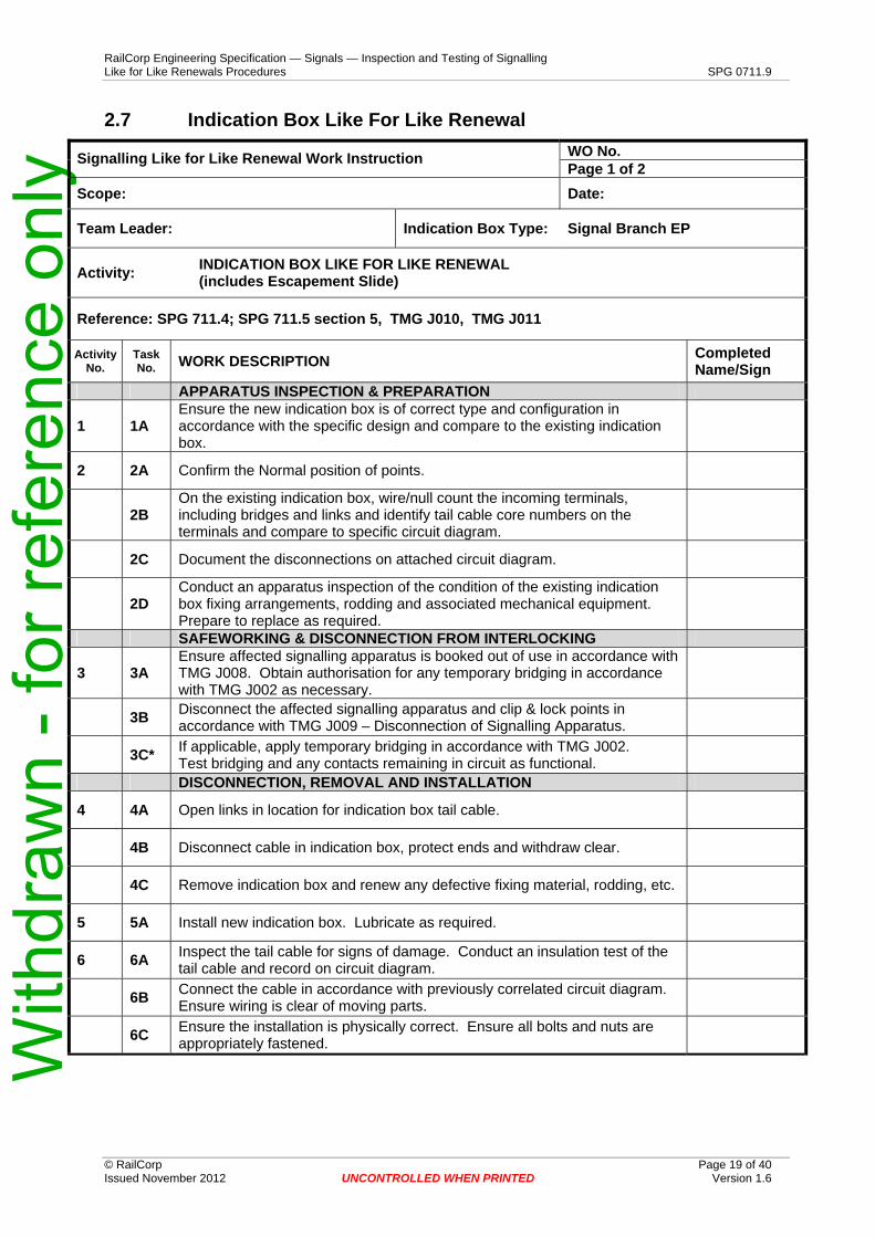
1 1A Ensure the new indication box is of correct type and configuration in accordance with the specific design and compare to the existing indication box.
2 2A Confirm the Normal position of points.
2B On the existing indication box, wire/null count the incoming terminals, including bridges and links and identify tail cable core numbers on the terminals and compare to specific circuit diagram.
2C Document the disconnections on attached circuit diagram.
2D Conduct an apparatus inspection of the condition of the existing indication box fixing arrangements, rodding and associated mechanical equipment. Prepare to replace as required. SAFEWORKING & DISCONNECTION FROM INTERLOCKING
3 3A Ensure affected signalling apparatus is booked out of use in accordance with TMG J008. Obtain authorisation for any temporary bridging in accordance with TMG J002 as necessary.
3B Disconnect the affected signalling apparatus and clip & lock points in accordance with TMG J009 – Disconnection of Signalling Apparatus.
3C* If applicable, apply temporary bridging in accordance with TMG J002. Test bridging and any contacts remaining in circuit as functional. DISCONNECTION, REMOVAL AND INSTALLATION
4 4A Open links in location for indication box tail cable.
4B Disconnect cable in indication box, protect ends and withdraw clear.
4C Remove indication box and renew any defective fixing material, rodding, etc.
5 5A Install new indication box. Lubricate as required.
6 6A Inspect the tail cable for signs of damage. Conduct an insulation test of the tail cable and record on circuit diagram.
6B Connect the cable in accordance with previously correlated circuit diagram. Ensure wiring is clear of moving parts.
6C Ensure the installation is physically correct. Ensure all bolts and nuts are appropriately fastened.
RailCorp Engineering Specification — Signals — Inspection and Testing of Signalling Like for Like Renewals Procedures SPG 0711.9
Indication Box Like for Like Renewal Page 2 of 2
APPARATUS ADJUSTMENT
7 7A Adjust indication box for correct operation and adjustment.
CERTIFICATION
8 8A Wire count all terminals with incoming tail cable installation to circuit diagram (NB: links to be counted as wire). Record on circuit diagram.
9 9A Close all associated terminal links in location and remove any temporary bridging (if applicable).
10* 10A*
Conduct a Points Correspondence Test Normal - Operate points to the Normal position and open each contact in the Normal detection circuit in turn and ensure Normal detection is lost and restored. Remove and replace EOL/ESML and ensure Normal detection is lost and restored. Each contact# tested during the correspondence test shall be observed to “open” when the points are operated to the Reverse position. #denotes not required for encapsulated contacts which are back-proved in the opposite position.
10B*
Conduct a Points Correspondence Test Reverse - Operate the points to the Reverse position and open each contact in the Reverse detection circuit in turn and ensure Reverse detection is lost and restored. Remove and replace EOL/ESML and ensure Reverse detection is lost and restored. Each contact# tested during the correspondence test shall be observed to “open” when the points are operated to the Normal position. #denotes not required for encapsulated contacts which are back-proved in the opposite position.
10C* Conduct an Out of Correspondence test of the following combinations and ensure no detection. Note: The following combinations only apply for an existing double-ended layout. A Signal Engineer shall be consulted if the layout consists of more than two ends.
Out of correspondence test for existing double-ended
layout
Operate points to Normal (both ends Normal) A end
hold Normal Operate points lever
Reverse B end
Reverse B end
hold Reverse Operate points lever
Normal (ensure NWR is energised) A end
Normal Operate points to Reverse (both ends Reverse)
A end hold Reverse
Operate points lever Normal
B end Normal
B end hold Normal
Operate points lever Reverse (ensure RWR is
energised)
A end Reverse
11* 11A* Certify the Facing Point Lock and Detection Normal & Reverse.
12 12A Arrange for the signaller to check the operation of the points, signals and indications associated with the apparatus. Ensure the indication box is secure.
12B* Complete the return SFJ017.
12C Book affected signalling apparatus back into use.
I certify ______ points at _________________ location have been inspected and tested and are fit for service.
________________________ Print Name Position
______/_____/_____ Signature Date
___________________________
___________________________
*Not required where the Escapement Slide contain "escapement contacts" only.
1 1A Ensure the new plunger lock is of correct type and configuration in accordance with the specific design and compare to the existing plunger lock.
2 2A Confirm the Normal position of points.
2B On the existing plunger lock, wire/null count the incoming terminals, including bridges and links and identify tail cable core numbers on the terminals and compare to specific circuit diagram.
2C Document the disconnections on attached circuit diagram.
2D Conduct an apparatus inspection of the condition of the existing plunger lock fixing arrangements, rodding and associated mechanical equipment. Prepare to replace as required. SAFEWORKING & DISCONNECTION FROM INTERLOCKING
3 3A Ensure affected signalling apparatus is booked out of use in accordance with TMG J008. Obtain authorisation for any temporary bridging in accordance with TMG J002 as necessary.
3B Disconnect the affected signalling apparatus and clip & lock points in accordance with TMG J009 – Disconnection of Signalling Apparatus.
3C If applicable, apply temporary bridging in accordance with TMG J002. Test bridging and any contacts remaining in circuit as functional. DISCONNECTION, REMOVAL AND INSTALLATION
4 4A Open links in location for plunger lock tail cable and turn-off air supply valve to the plunger lock (points air supply).
4B Disconnect cable and air line in plunger lock, protect ends and withdraw clear.
4C Remove plunger lock assembly and renew any defective fixing material, rodding, etc.
5 5A Install new plunger lock assembly. Lubricate as required.
6 6A Inspect the tail cable and air line for signs of damage. Conduct an insulation test of the tail cable and record on circuit diagram.
6B Connect the cable in accordance with previously correlated circuit diagram. Ensure wiring is clear of moving parts. Connect the air line to the plunger lock and reopen the air valve.
6C Ensure the installation is physically correct. Ensure all bolts and nuts are appropriately fastened. Ensure no air leaks.
RailCorp Engineering Specification — Signals — Inspection and Testing of Signalling Like for Like Renewals Procedures SPG 0711.9
Plunger Lock Assembly Like for Like Renewal Page 2 of 2
APPARATUS ADJUSTMENT
7 7A
Adjust the plunger so it passes through the facing point lock notch in the stretcher bar and withdraws clear of the stretcher bar correctly and that the connection to the indication box is correct. Adjust the plunger lock so it engages in the facing point lock plunger to the full depth of the notch and is located in the centre of the notch for both Normal and Reverse. Ensure full movement of plunger lock motor and lock dog.
7B Adjust the plunger lock Normal contacts to be open until the lock is engaged in the notch by at least 2 mm. Adjust the Reverse contacts to be open until the lock is clear of the plunger by 1mm. CERTIFICATION
8 8A Wire count all terminals with incoming tail cable installation to circuit diagram (NB: links to be counted as wire). Record on circuit diagram.
9 9A Close all associated terminal links in location and remove any temporary bridging (if applicable).
10 10A
Conduct a Points Correspondence Test Normal - Operate points to the Normal position and open each contact in the Normal detection circuit in turn and ensure Normal detection is lost and restored. Remove and replace EOL (if applicable) and ensure Normal detection is lost and restored. Each contact# tested during the correspondence test shall be observed to “open” when the points are operated to the Reverse position. #denotes not required for encapsulated contacts which are back-proved in the opposite position.
10B
Conduct a Points Correspondence Test Reverse - Operate the points to the Reverse position and open each contact in the Reverse detection circuit in turn and ensure Reverse detection is lost and restored. Remove and replace EOL (if applicable) and ensure Reverse detection is lost and restored. Each contact# tested during the correspondence test shall be observed to “open” when the points are operated to the Normal position. #denotes not required for encapsulated contacts which are back-proved in the opposite position.
10C Conduct an Out of Correspondence test of the following combinations and ensure no detection. Note: The following combinations only apply for an existing double-ended layout. A Signal Engineer shall be consulted if the layout consists of more than two ends.
Out of correspondence test for existing double-ended
layout
Operate points to Normal (both ends Normal) A end
hold Normal Operate points lever
Reverse B end
Reverse
B end hold Reverse
Operate points lever Normal (ensure NWR is energised)
A end Normal
Operate points to Reverse (both ends Reverse) A end
hold Reverse Operate points lever
Normal B end
Normal
B end hold Normal
Operate points lever Reverse (ensure RWR is energised)
A end Reverse
11 11A Certify the Facing Point Lock and Detection Normal & Reverse.
12 12A Arrange for the signaller to check the operation of the points, signals and indications associated with the apparatus. Ensure the plunger lock is secure.
12B Complete the return SFJ017.
12C Book affected signalling apparatus back into use.
I certify ______ points at _________________ location have been inspected and tested and are fit for service.
1 1A Ensure the new signal is of correct type, profile and configuration in accordance with the specific design and compare to the existing signal. Document the signal profile.
1B
Bell test and wire/null count internal wiring of the new signal, compare to the specific circuit design and existing signal. Include a correlation of busbars, connected links and bridges to the circuit book. Also applies to the trainstop cable terminals (in the signal base) if connected through the signal. Visually inspect (as accessible) and insulation test the internal wiring.
2 2A On the existing signal, wire/null count the incoming terminals, including bridges and links and identify tail cable core numbers on the terminals and compare to specific circuit diagram. Also applies to the trainstop cable terminals (in the signal base) if connected through the signal.
2B Document the disconnections on attached circuit diagram.
2C Conduct an apparatus inspection of the condition of the existing signal mounting/fixing arrangements. Prepare to replace as required. SAFEWORKING & DISCONNECTION FROM INTERLOCKING
3 3A Ensure the affected signal is booked out of use in accordance with TMG J008.
3B Disconnect the signal (and associated trainstop if applicable) in accordance with TMG J009 – Disconnection of Signalling Apparatus. DISCONNECTION, REMOVAL AND INSTALLATION
4 4A Open links in location for signal (and trainstop if connected through the signal) tail cable(s).
4B Disconnect cable(s) from signal, protect ends and withdraw clear.
4C Remove signal and renew any defective fixing material.
5 5A Install new signal and ensure correct to structure gauge.
6 6A Inspect the tail cables for signs of damage. Conduct an insulation test of the tail cable(s) and record on circuit diagrams.
6B Connect the cable(s) to the signal in accordance with previously correlated circuit diagram.
6C Ensure the installation is physically correct. Ensure all bolts and nuts are appropriately fastened.
RailCorp Engineering Specification — Signals — Inspection and Testing of Signalling Like for Like Renewals Procedures SPG 0711.9
Signal Like for Like Renewal Page 2 of 2
APPARATUS ADJUSTMENT
7 7A Close all associated terminal links in location. Operate signal (and trainstop if applicable) and confirm correct operation.
7B Focus the complete signal for correct alignment.
CERTIFICATION
8 8A Wire count all terminals with incoming tail cable installation to circuit diagram (NB: links to be counted as wire). Record on circuit diagram. Also applies to the trainstop cable terminals (in the signal base) if connected through the signal. Record on circuit diagrams.
9 9A As applicable for trainstop: Operate the trainstop Normal contacts or contact device and ensure VNR is de-energised and energised accordingly.
9B As applicable for trainstop: Operate the trainstop Reverse contacts or contact device and ensure VRR is de-energised and energised accordingly.
10 10A Ensure correct signal profile (including name plate and other signage). Ensure staggered heads where necessary.
10B Confirm correct lamp/led voltage and no-voltage.
11 11A Arrange with the signaller to conduct a functional test of the signal for each signal route - first aspect. Ensure the trainstop, operates as per design (if applicable).
11B Arrange with the signaller to clear signal(s) in advance and functionally test each aspect correctly sequences. Ensure the trainstop, operates as per design (if applicable).
12 12A Ensure signal (and trainstop if applicable) is secure.
12B Complete the TC1 certificate.
12C Book signal back into use.
I certify ______ signal (and trainstop if applicable) at _________________ location have been inspected and tested and are fit for service.
1 1A Ensure the new trainstop is of correct type and configuration in accordance with the specific design and compare to the existing trainstop. Ensure trip-arm face is painted white. Ensure VNR/VRR contacts centre when trip-arm is disengaged from detector-arm.
1B Bell test and wire/null count internal wiring (essentially the VNR & VRR circuits) of the new trainstop, compare to the specific circuit design and existing trainstop. Include a correlation of connected links and bridges to the circuit book. Visually inspect and insulation test the internal wiring.
2 2A On the existing trainstop, wire/null count the incoming terminals, including bridges and links and identify tail cable core numbers on the terminals and compare to specific circuit diagram.
2B Document the disconnections on attached circuit diagram.
2C Conduct an apparatus inspection of the condition of the existing trainstop sleeper fixing arrangements, protection ramps, and cable/air supply. Prepare to replace as required. SAFEWORKING & DISCONNECTION FROM INTERLOCKING
3 3A Ensure associated signal and trainstop are booked out of use in accordance with TMG J008.
3B Disconnect the associated signal and trainstop in accordance with TMG J009 – Disconnection of Signalling Apparatus. DISCONNECTION, REMOVAL AND INSTALLATION
4 4A Open links in location for trainstop tail cables (and turn off air supply valve to trainstop if applicable).
4B Disconnect cables (and air line if applicable) from trainstop, protect ends and withdraw clear.
4C Remove trainstop and renew any defective sleeper fixing material.
5 5A Install new trainstop. Lubricate detector-arm.
6 6A Inspect the tail cables (and airline if applicable) for signs of damage. Conduct an insulation test of the tail cables and record on circuit diagrams.
6B Connect the cables (and air line if applicable) in accordance with previously correlated circuit diagram.
6C Ensure the installation is physically correct. Ensure all bolts and nuts are appropriately fastened.
RailCorp Engineering Specification — Signals — Inspection and Testing of Signalling Like for Like Renewals Procedures SPG 0711.9
Trainstop Like for Like Renewal Page 2 of 2
APPARATUS ADJUSTMENT
7 7A Adjust as necessary, the trip-arm, safety latch and limit switch for correct operation.
7B Adjust as necessary, the VNR/VRR contacts to correctly open and close when the trip-arm is operated. Check that the Normal contacts do not open when the trip-arm is manually suppressed against the safety latch.
7C Ensure lubricating oil, automatic feeder and hydraulic levels are correct, if applicable.
7D Close all associated terminal links in location (and reopen the air valve if applicable) and operate trainstop under power and confirm correct operation. Ensure no air leaks (if applicable). CERTIFICATION
8 8A Wire count all terminals with incoming tail cable installation to circuit diagram (NB: links to be counted as wire). Record on circuit diagram.
9 9A Ensure trainstop is correct to gauge.
10 10A With the trainstop Normal, operate the trainstop Normal contacts or contact device and ensure VNR is de-energised and energised accordingly.
10B With the trainstop Reverse, operate the trainstop Reverse contacts or contact device and ensure VRR is de-energised and energised accordingly.
11 11A Arrange the signaller to conduct a functional test of the trainstop in conjunction with the associated signal. Ensure the trainstop is secure.
11B Complete the return SFJ017.
11C Book signal and trainstop back into use.
I certify ______ trainstop at _________________ location has been inspected and tested and is fit for service.
1 1A Examine and bench test new (overhauled relay) for correct operation. Ensure relay is sealed and seals are not damaged.
1B If a DC shelf-mounted relay: test the "pick-up", "drop-away" and "working" currents of the new relay.
1C Confirm the new relay is of the same type and contact configuration as the one to be replaced and as shown in the circuit book analysis. Observe each relay contact to ensure it is of the correct type (front or back) and opens and closes correctly.
1D Check the wiring on the existing relay against the circuit book contact analysis sheet. Any discrepancy to be investigated by the Maintenance Signal Engineer.
1E Confirm that the locknuts between studs and relay top on the new relay are tight.
Note: If a detachable top is fitted perform activity 2A then go to activities 5B – 5F. If relay is direct wired perform activities 3A – 5F. CHANGE OVER – detachable top only
2 2A Change the relay after obtaining train running information and reaching an understanding with the signaller for safe working as traffic conditions permit. Request signaller to install blocks on protecting signals. WIRING CONFIRMATION – direct wired only
3 3A Examine relay to find which terminals are not in use.
3B On the new relay fit nuts and washers to the corresponding spare terminals and tighten. Fit bottom washers only to the terminals to be used.
3C Confirm any bridges on the existing relay and fit the same bridges on the new relay before installation. Tighten down nuts.
3D Ensure that each and every wire on the existing relay is correctly labelled with its terminal number and circuit name, and that the wiring is securely tied with multiple ties in a firm loom corresponding to the relay terminal configuration.
3E Write down the relay contact configuration, wire count and null count for each terminal on the relay on a copy of the contact analysis sheet attached to work package.
3F Compare actual wire count and null count against the circuit book and the contact analysis sheet. Any discrepancy to be investigated by the Maintenance Signal Engineer.
3G Contact signal box for train running information, advise the signaller the relay is to be changed and reach an understanding for the safe working as traffic conditions permit. Arrange protecting signals to be maintained at stop and blocks applied.
RailCorp Engineering Specification — Signals — Inspection and Testing of Signalling Like for Like Renewals Procedures SPG 0711.9
Shelf Relay Like for Like Renewal Page 2 of 2
CHANGE OVER – direct wired only
4 4A Remove the nuts, locknuts and washers from the existing relay and lift wiring loom clear, ensuring that no wire touches any metal shelf/bracket or any other relay or relay stud and the wiring is not disturbed.
4B Immediately remove the existing relay and replace it with the new one.
4C Lower the wiring loom onto the new relay and check that the terminal number on each wire label corresponds with the relay terminal to which the wire is fitted- fit washers and nuts.
4D Check if any bridges are left on the replaced relay once removed from shelf.
CERTIFICATION
5 5A Confirm relay wiring against written down wire count and null count on circuit book analysis sheet (record by ticking the wire /null count in the copy of contact analysis sheet - results from step 3E & 3F).
5B Observe that the relay correctly energises and de-energises.
5C
Verify each controlled function in turn by energising and de-energising relay replaced and observing each end controlling function operates as per circuit design for each and every relay contact on the relay replaced (record by ticking the contact function name in the copy of contact analysis sheet for each contact).
5D If a track relay: ensure that the shunt value is within the permissible range of values for the type of track. Ensure the local coil voltage and current and track coil voltage and current are correct. Update the Track History Card.
Note If any doubt or delay arises during the process that could put at risk the safety of the signalling, the affected functions through the relay contacts shall be disconnected and booked out of use before changeover until certified by Circuit Strap and Function Tests after the changeover.
5E Advise the signaller that the work is complete and the affected signalling is available for use (includes the removal of applied blocks).
5F Complete and sign relay change form SF J024/B.
I certify ______ relay at _________________ location has been inspected and tested and is fit for service.
1 1A Ensure the new releasing switch is of correct type and configuration in accordance with the specific design and compare to the existing releasing switch.
1B
Bell test and wire/null count internal wiring of the new releasing switch, compare to the specific circuit design and existing releasing switch. Include a correlation of connected links and bridges to the circuit book. Visually inspect the releasing switch components including the Annett Lock and wardings and insulation test the internal wiring.
2 2A On the existing releasing switch, wire/null count the incoming terminals, including bridges and links and identify tail cable core numbers on the terminals and compare to specific circuit diagram.
2B Document the disconnections on attached circuit diagram.
2C Conduct an apparatus inspection of the condition of the existing releasing switch fixing arrangements and cable. Prepare to replace as required. SAFEWORKING & DISCONNECTION FROM INTERLOCKING
3 3A Ensure the releasing switch & associated signalling is booked out of use in accordance with TMG J008. Obtain authorisation for any temporary bridging in accordance with TMG J002 as necessary.
3B Disconnect the releasing switch & associated signalling in accordance with TMG J009 – Disconnection of Signalling Apparatus.
3C If applicable, apply temporary bridging in accordance with TMG J002. Test bridging and any contacts remaining in circuit as functional. DISCONNECTION, REMOVAL AND INSTALLATION
4 4A Open links in location for releasing switch tail cable(s).
4B Disconnect cable(s) from releasing switch, protect ends and withdraw clear. Safeguard the Annett Key.
4C Remove releasing switch and renew any defective fixing material.
5 5A Install new releasing switch and Annett Lock. Lubricate components as required.
6 6A Inspect the tail cable(s) for signs of damage. Conduct an insulation test of the tail cable(s) and record on circuit diagrams.
6B Connect the cable(s) in accordance with previously correlated circuit diagram. Return Annett Key to Annett Lock.
6C Ensure the installation is physically correct. Ensure all bolts and nuts are appropriately fastened. Include inspection of Annett Lock and Key.
RailCorp Engineering Specification — Signals — Inspection and Testing of Signalling Like for Like Renewals Procedures SPG 0711.9
Releasing Switch Like for Like Renewal Page 2 of 2
APPARATUS ADJUSTMENT
7 7A Adjust and operate releasing switch for correct operation.
7B Close all associated terminal links in location and remove any temporary bridging (if applicable) and operate releasing switch and confirm correct operation. CERTIFICATION
8 8A Wire count all terminals with incoming tail cable(s) installation to circuit diagram (NB: links to be counted as wire). Record on circuit diagram.
9 9A Test all contacts/circuits that were temporarily bridged to ensure complete removal.
10 10A Test the lock and proving contacts Normal and Reverse. Observe each proving contact to ensure it is of the correct type (N/O or N/C) and opens and closes correctly.
11 11A Arrange the signaller to conduct a functional test of the releasing switch. Ensure the releasing switch is secure.
11B Book releasing switch & associated signalling back into use.
I certify ______ releasing switch at _________________ location has been inspected and tested and is fit for service.
1 1A Ensure the new Road Boom Gate mechanism including Motor Control Relay (K2) is of the correct configuration. Inspect equipment type and the configuration are in accordance with the specific circuit design and compare to the existing Road Boom Gate mechanism. Also compare the Counterweight positions
1B
Bell test and wire/null count the internal wiring of the new Road Boom Gate mechanism and compare to the specific circuit design and existing Road Boom Gate mechanism. Include a correlation of connected links and bridges to the circuit book. Visually inspect and conduct an insulation test of the internal wiring of the new Road Boom Gate mechanism. Ensure that circuit controller contacts are in the correct position as per the specific circuit design.
2 2A On the existing Road Boom Gate mechanism, wire/null count the incoming terminals, including bridges, links and identify cable numbers on the terminals and compare to issued/current circuit book design.
2B Document the disconnections on the attached circuit diagram.
2C Conduct an apparatus inspection of the condition of the existing post, mounting brackets, fixings and fittings. Ensure existing mechanism Rest is secure. SAFEWORKING & DISCONNECTION FROM INTERLOCKING
3 3A Switch the Cerberus Monitor to "maintenance mode" to prevent any unnecessary alarms. Advise IOC of the intended work.
3B Ensure affected signalling apparatus is booked out of use in accordance with TMG J008. Obtain authorisation for any temporary bridging in accordance with TMG J002 as necessary.
3C Disconnect the affected signalling apparatus in accordance with TMG J009 – Disconnection of Signalling Apparatus.
3D If applicable, apply temporary bridging in accordance with TMG J002. Test bridging and that any contacts remaining in the circuit are functional. DISCONNECTION, REMOVAL AND INSTALLATION
4 4A Open links in location for the Road Boom Gate mechanism tail cable/s.
4B Disconnect cable/s in the Road Boom Gate mechanism, protect ends and withdraw clear. Secure or remove Motor Control Relay.
4C Remove the Counterweights, Road Boom Arm and wiring connections, mounting bolts and remove the mechanism.
5 5A Install the new Road Boom Gate mechanism, Road Boom Arm and Counterweights. Secure mounting brackets, nuts, and bolts and split pins. Remove securing material from Motor Control Relay.
RailCorp Engineering Specification — Signals — Inspection and Testing of Signalling Like for Like Renewals Procedures SPG 0711.9
Road Boom Gate Mechanism Like For Like Renewal Page 2 of 2
6 6A Connect all cables in accordance with previously correlated circuit diagram.
6B Inspect the cable/s for any signs of damage. Conduct an insulation test of the tail cable/s and record on circuit diagrams.
7 7A Lubricate the Road Boom Gate mechanism and motor ensuring that oil-ways are clear and all oiling cup caps are refitted, where applicable. ADJUSTMENT
8 8A
Make any adjustments necessary to the Road Boom Gate mechanism drive and the vertical and horizontal torque (Counterweight position). Also check for correct operation of the circuit controller contacts, operating-clutch, holding-clutch, ratchet & pawl gap and magnetic brake - adjust as necessary where applicable.
8B Conduct a safety, security and reliability inspection of the fixings, locking tabs, boom gate arm, nuts, bolts and split pins. Ensure that the correct shear pin arrangement is in place for the Boom Gate Arm length.
8C Conduct a power test of the Road Boom Gate mechanism and check operation of Motor Control Relay, Circuit Controller. Check the Road Boom Arm Raised and Lowered positions and speed of operation (rise and descent) are correct. Adjust if required. CERTIFICATION
9 9A Conduct a wire count all terminals with incoming tail cable/s installation to circuit diagram (NB: links to be counted as wire). Record on circuit diagram.
10 10A Close all associated terminal links in the location and remove any temporary bridging (if applicable).
11 11A Arrange to operate the level crossing protection equipment and ensure the Road Boom Gate mechanism operates correctly with smooth motion from the motor/gearbox. Ensure the hold-clear armature falls away freely and without hesitation from the ratchet gear.
11B Check correct operation of Post and Boom Arm Lights, Bell, Motor Drive Up, Motor Drive Down, Snubbing and XNR.
12 12A
Conduct a Correspondence Test of the Normal Road Boom Arm detection (XNR) where applicable. Operate all Road Boom Arms to the lowered position (0°) and raise each boom arm in turn to ensure the XNR relay de-energises and restores. Observe each proving contact to ensure it is of the correct type (N/O or N/C) and opens and closes correctly.
13 13A Ensure that any alarms raised with Cerberus monitor are cleared. Switch Cerberus monitor out of "maintenance mode".
14 14A Arrange with the signaller to conduct an operational test of the affected signalling equipment in association with the level crossing protection equipment. Ensure the Road Boom Gate mechanism is secure.
14B Book affected signalling apparatus back into use.
I certify that the __________________Side Road Boom Gate mechanism at _________________ Level Crossing location has been inspected tested and is fit for service.
1 1A Ensure the new Pedestrian Swing Gate mechanism is of correct configuration. Inspect the equipment type and the configuration are in accordance with the specific design and compare to the existing Pedestrian Swing Gate mechanism.
1B
Bell test and wire/null count the internal wiring of the new Pedestrian Swing Gate mechanism and compare to the specific circuit design and existing Pedestrian Swing Gate mechanism. Include a correlation of connected links and bridges to the circuit book. Visually inspect and insulation test the internal wiring of the new Pedestrian Swing gate mechanism.
2 2A On the existing Pedestrian Swing Gate mechanism, wire/null count the incoming terminals, including bridges, links and identify cable numbers on the terminals and compare to specific circuit diagram.
2B Document the disconnections on attached circuit diagram.
2C Conduct an apparatus inspection of the condition of the existing drive point fixings. SAFEWORKING & DISCONNECTION FROM INTERLOCKING
3 3A Switch the Cerberus Monitor to "maintenance mode" to prevent any unnecessary alarms. Advise IOC of the intended work.
3B Ensure affected signalling apparatus is booked out of use in accordance with TMG J008. Obtain authorisation for any temporary bridging in accordance with TMG J002 as necessary.
3C Disconnect the affected signalling apparatus in accordance with TMG J009 – Disconnection of Signalling Apparatus. Note – the Pedestrian Swing Gate must not to be tied open.
3D If applicable, apply temporary bridging in accordance with TMG J002. Test bridging and that any contacts remaining in the circuit are functional. DISCONNECTION, REMOVAL AND INSTALLATION
4 4A Open links in location for the Pedestrian Swing Gate mechanism tail cable/s.
4B Disconnect cable/s in the Pedestrian Swing Gate mechanism, protect ends and withdraw clear.
4C Disconnect the Pedestrian Swing Gate linkage arm and mounting bolts and remove the mechanism.
5 5A Install the new Pedestrian Swing Gate mechanism, connect linkage arm and connect all securing nuts, bolts and split pins.
6 6A Connect all cables in accordance with previously correlated circuit diagram.
6B Inspect the cable/s for any signs of damage. Conduct an insulation test of the tail cable/s and record on circuit diagrams.
7 7A Lubricate the Pedestrian Swing Gate hinges to ensure reliable operation.
RailCorp Engineering Specification — Signals — Inspection and Testing of Signalling Like for Like Renewals Procedures SPG 0711.9
Pedestrian Swing Gate Mechanism Like for Like Renewal Page 2 of 2
ADJUSTMENT
8 8A Conduct a safety, security and reliability inspection of the fixings, locking tabs, parallel locking bush set screws, Pedestrian Swing Gate linkage arms, nuts, bolts and split pins. Ensure linkages are clear of fencing.
8B Conduct a power test of the Pedestrian Swing Gate mechanism operation with the Return Spring disconnected; check the gate will open and close correctly from the fully Open and Closed positions. Adjust if required. Reinstate the Return Spring.
8C Make any adjustments necessary to the Pedestrian Swing Gate mechanism drive, return spring, linkage arms and motor cut out to enable gate to become operational. CERTIFICATION
9 9A Wire count all terminals with incoming tail cable/s installation to circuit diagram (NB: links to be counted as wire). Record on circuit diagram.
10 10A Close all associated terminal links in the location and remove any temporary bridging (if applicable).
11 11A
Arrange to operate the level crossing protection equipment and ensure the Pedestrian Swing Gate operates correctly with smooth, noise-free motion from the motor/gearbox. Ensure there is no hesitation of the gate movement to close when activated. Ensure motor power has reduced when the gate is in either the fully Opened or Closed Position.
11B Ensure the Tone Generator DIP switch settings are correct and ensure correct operation of the Tone Generator.
11C Ensure correct operation of Red Man Light indication.
12 12A Conduct a Correspondence Test of the Normal Pedestrian Swing Gate detection (XNR) where applicable. Operate all gates to the Closed position and open each gate in turn to ensure the XNR relay de-energises and restores.
12B Conduct a Correspondence Test of the Reverse Pedestrian Swing Gate detection (XRR) where applicable. Operate all gates to the Open position and close each gate in turn to ensure the XRR relay de-energises and restores.
13 13A Test the Indexed Coupling by forcing the Pedestrian Swing Gate toward the Closed position (from the fully Open position) until the coupling produces a clicking noise. Release the Swing gate and ensure it returns to the preset position.
13B Test the operation of the Pedestrian Swing Gate mechanism return spring, by ensuring the Swing Gate fully closes after the removal of power from the motor. Repeat test from 10 degrees of the full Closed position.
13C Ensure the Pedestrian Swing Gate when fully closed, cannot be forced open easily.
14 14A Ensure that any alarms raised with Cerberus monitor are cleared. Switch Cerberus monitor out of "maintenance mode".
15 15A Arrange with the signaller to conduct an operational test of the affected signalling equipment in association with the level crossing protection equipment. Ensure the Pedestrian Swing Gate mechanism is secure.
15B Book affected signalling apparatus back into use.
I certify that the __________________Side Pedestrian Swing Gate mechanism at _________________ Level Crossing location has been inspected, tested and is fit for service.
1 1A Ensure the new Pedestrian Boom Gate mechanism is of correct configuration. Inspect equipment type and configurations are in accordance with the specific design and compare to the existing Pedestrian Boom Gate mechanism.
1B
Bell test and wire/null count the internal wiring of the new Pedestrian Boom Gate mechanism and compare to the specific circuit design and existing Pedestrian Boom Gate mechanism. Include a correlation of connected links and bridges to the circuit book. Visually inspect and insulation test the internal wiring of the new Pedestrian Boom gate mechanism.
2 2A On the existing Pedestrian Boom Gate mechanism, wire/null count the incoming terminals, including bridges, links and identify cable numbers on the terminals and compare to specific circuit diagram.
2B Document the disconnections on attached circuit diagram.
2C Conduct an apparatus inspection of the condition of the existing drive point fixings. SAFEWORKING & DISCONNECTION FROM INTERLOCKING
3 3A Switch the Cerberus Monitor to "maintenance mode" to prevent any unnecessary alarms. Advise IOC of the intended work.
3B Ensure affected signalling apparatus is booked out of use in accordance with TMG J008. Obtain authorisation for any temporary bridging in accordance with TMG J002 as necessary.
3C Disconnect the affected signalling apparatus in accordance with TMG J009 – Disconnection of Signalling Apparatus. Note – the Pedestrian Boom Gate must not to be tied open.
3D If applicable, apply temporary bridging in accordance with TMG J002. Test bridging and that any contacts remaining in the circuit are functional. DISCONNECTION, REMOVAL AND INSTALLATION
4 4A Open links in location for the Pedestrian Boom Gate mechanism tail cable/s.
4B Disconnect cable/s in the Pedestrian Boom Gate mechanism, protect ends and withdraw clear.
4C Disconnect the Pedestrian Boom Gate arm and mounting bolts and remove the mechanism.
5 5A Install the new Pedestrian Boom Gate mechanism, boom arm and connect all securing nuts, bolts and split pins.
5B Ensure the Locking Dog is removed from the Pedestrian Boom Gate mechanism.
6 6A Connect all cables in accordance with previously correlated circuit diagram.
RailCorp Engineering Specification — Signals — Inspection and Testing of Signalling Like for Like Renewals Procedures SPG 0711.9
Pedestrian Boom Gate Mechanism Like for Like Renewal Page 2 of 2
6B Inspect the cable/s for any signs of damage. Conduct an insulation test of the tail cable/s and record on circuit diagrams.
7 7A Lubricate the Pedestrian Boom Gate spectacle arm oil-wells to ensure reliable operation. ADJUSTMENT
8 8A Make any adjustments necessary to the Pedestrian Boom Gate mechanism drive and particularly check the boom gate arm rate of descent. Also check for correct operation of the operating-clutch, holding-clutch and ratchet & pawl gap adjust as necessary.
8B Conduct a safety, security and reliability inspection of the fixings, locking tabs, boom gate arm, nuts, bolts and split pins.
8C Conduct a power test of the Pedestrian Boom Gate mechanism operation; check the boom Raised and Lowered positions are correct. Adjust if required. CERTIFICATION
9 9A Wire count all terminals with incoming tail cable/s installation to circuit diagram (NB: links to be counted as wire). Record on circuit diagram.
10 10A Close all associated terminal links in the location and remove any temporary bridging (if applicable).
11 11A Arrange to operate the level crossing protection equipment and ensure the Pedestrian Boom Gate operates correctly with smooth motion from the motor/gearbox. Ensure the hold-clear armature falls away from ratchet gear without hesitation.
11B Ensure correct operation of Red Man light indication.
12 12A
Conduct a Correspondence Test of the Normal Pedestrian Boom Gate detection (XNR) where applicable. Operate all Pedestrian Boom Gates to the Lowered position (0°) and raise each boom gate in turn to ensure the XNR relay deenergises and restores. Observe each proving contact to ensure it is of the correct type (N/O or N/C) and opens and closes correctly.
12B
Conduct a Correspondence Test of the Reverse Pedestrian Boom Gate detection (XRR) where applicable. Operate all Pedestrian Boom Gates to the Raised position (90°) and lower each boom in turn to ensure the XRR relay deenergises and restores. Observe each proving contact to ensure it is of the correct type (N/O or N/C) and opens and closes correctly.
13 13A Ensure the Pedestrian Boom Gate when fully lowered, can be lifted easily.
14 14A Ensure that any alarms raised with Cerberus monitor are cleared. Switch Cerberus monitor out of "maintenance mode".
15 15A Arrange with the signaller to conduct an operational test of the affected signalling equipment in association with the level crossing protection equipment. Ensure the Pedestrian Boom Gate mechanism is secure.
15B Book affected signalling apparatus back into use.
I certify that the __________________Side Pedestrian Boom Gate mechanism at _________________ Level Crossing location has been inspected tested and is fit for service.
1 1A Compare the existing relay & relay base to the specific circuit design and ensure it is of correct configuration and type.
1B Ensure the new relay base is of correct configuration and type, including pin coding and labelling, in accordance with the specific design.
2 2A Wire/null count wiring terminated to the existing relay base and compare to the specific circuit design. Include a correlation of beads/tags associated with the relay base wires and ensure they are commensurate with the relay base terminals.
3 3A Visually inspect the wiring and terminations for any defects.
4 4A Document the disconnections on an attached circuit diagram.
SAFEWORKING & DISCONNECTION FROM INTERLOCKING
5 5A Ensure affected signalling apparatus is booked out of use in accordance with TMG J008.
5B Remove the relay and place it in a safe area free of contaminants.
5C Remove the relay base securing clip.
DISCONNECTION, REMOVAL AND INSTALLATION
6 6A
Carefully transfer the terminated wires from the existing relay base to the new relay base one lug at a time, taking care to insert the wire into the correct receptacle. Take care not to short circuit the live connection. Examine each lug and ensure satisfactory condition before inserting. When inserting the lug ensure a definite "click" sound is heard. Tug the wire lightly to check that it is secure and will not fall out.
6B Remove the existing relay base mounting screws and remove the old base.
6C Install the new relay base in position taking care not to dislodge the terminated wires. Secure the mounting screws taking care not to over tightening as this may crack the base. Install the relay base securing clip.
7 7A Visually inspect the wiring and terminations for any defects, ensuring each wire and lug is securely terminated.
8 8A Correlate the beads/tags associated with the relay base wiring and ensure they are commensurate with the relay base terminals.
8B Ensure terminated wiring is in accordance with previously correlated circuit diagram.
RailCorp Engineering Specification — Signals — Inspection and Testing of Signalling Like for Like Renewals Procedures SPG 0711.9
Relay Base (plug-in) Like For Like Renewal Page 2 of 2
CERTIFICATION
9 9A Wire/null count wiring terminated on the new relay base and compare to the specific circuit design. Record on circuit diagram.
10 10A Test relay in test panel and if satisfactory insert in new relay base. Insert cleanly as not to damage contacts on rear of relay.
11 11A Perform a Circuit Function Test of circuits operating through the relay with both the relay energised (front contacts) and relay de-energised (backcontacts).
12 12A Arrange for the signaller to check the operation of the affected signalling and indications associated with the relay. Ensure the relay is secured in the base.
12B Book affected signalling apparatus back into use.
I certify the relay base for _________________ Relay has been replaced and tested and is fit for service.
RailCorp Engineering Specification — Signals — Inspection and Testing of Signalling Like for Like Renewals Procedures SPG 0711.9
2.17 Signalling Air-Line Component Like For Like Renewal
Signalling Like for Like Renewal Work Instruction WO No. Page 1 of 2
Scope: Date:
Team Leader: Apparatus Type:
Activity: SIGNALLING AIR-LINE COMPONENT LIKE FOR LIKE RENEWAL
Reference: TMG J008, TMG J010, TMG J011, SPG 0714, AIR SYSTEMS MANUAL
APPLICATION
This Work Instruction is intended for air-line work involving the replacement of a Like for Like component on the signalling air-line system, where the work
will NOT affect the working of operational signalling equipment.
Activity No. Task No. WORK DESCRIPTION Completed
Name/Sign APPARATUS INSPECTION & PREPARATION
1 1A Compare the existing air-line component to be replaced to the specific design and ensure it is of correct configuration and type.
1B Ensure the new component is of correct configuration and type in accordance with the specific design.
2 2A Inspect the new component and any fittings for defects.
3 3A Conduct an apparatus inspection of the components in the work area for signs of deterioration or damage that may affect the work.
4 4A
Analyse and document the air-line disconnection points on an attached airline diagram and determine if working signalling equipment will be affected by the work. If so, then the work shall be referred to the relevant Signalling Maintainer, otherwise if signalling not affected, continue with this work instruction. SAFEWORKING & DISCONNECTION FROM INTERLOCKING
5 5A Inform the relevant Signalling Maintainer of the intentions for the pending work.
5B Liaise with the Signaller and inform of intended work and provide contact details in event of inadvertent loss of signalling. Additionally, inform of potential air alarms triggered by the work.
6 6A Identify the limits of isolation and locate the isolation valves.
6B
Isolate the air supply to the air-line component intended for replacement. Ensure the air supply to operational signalling equipment is maintained. This can be achieved by feeding air from an alternate part of the air system or by fitting a temporary air compressor to the manifold. Do not rely on stored air in pipes, hoses or reservoirs, etc as this will eventually result in failure of the operating signalling apparatus.
6C Check with the Signaller that signalling equipment has not been affected by the air isolation. DISCONNECTION, REMOVAL AND INSTALLATION
7 7A Carry out the replacement of the air-line component
8 8A Once complete, restore air supply to the air-line system. Remove any temporary compressor device or other temporary arrangement (if used) as part of preparatory works.