Name Greg Hockings Peter McGregor Michael Uhlig Jagath Peiris
Position Principal Engineer, Electronic Systems
Lead Signals and Control Systems Engineer
A/Chief Engineer A/Director Network Standards and Services
With
draw
n - f
or re
fere
nce
only
DESIGN OF MICROLOK II INTERLOCKING
SPG 1230
Engineering Specification Signals Construction Specification
Version 1.7
Issued June 2013
Engi
neer
ing
Spec
ifica
tion
UNCONTROLLED WHEN PRINTED Page 1 of 183
Owner: Chief Engineer Signals & Control Systems
Approved Warwick Allison Authorised Paul Szacsvay by: Chief Engineer by: Principal Engineer
Signals & Control Systems Signal Research & Development
Disclaimer This document was prepared for use on the RailCorp Network only. RailCorp makes no warranties, express or implied, that compliance with the contents of this document shall be sufficient to ensure safe systems or work or operation. It is the document user’s sole responsibility to ensure that the copy of the document it is viewing is the current version of the document as in use by RailCorp. RailCorp accepts no liability whatsoever in relation to the use of this document by any party, and RailCorp excludes any liability which arises in any manner by the use of this document. Copyright The information in this document is protected by Copyright and no part of this document may be reproduced, altered, stored or transmitted by any person without the prior consent of RailCorp.
RailCorp Engineering Specification — Signals — Construction Specification Design of Microlok II Interlocking SPG 1230
Version Date Summary of change Version 1.1 of this document replaces Specification SC 05 43
00 00 SP Design of Microlok II Interlocking Version 1.3 of 3/10/2006
Section 3.5.2 – added reference to RS400 firmware version number plus use of UDP protocol instead of TCP
1.1 16 February 2010 Revised into RailCorp format and extensive updates throughout document.
1.2 1 March 2010 Section 3.2.5.1 – Reference to RS400 firmware and protocol
1.3
27 September 2010 Application of TMA 400 format Amendments to 3.2.5.1 & 3.7.1 for interface with RS400 2.8.2 – Note 10 JMP 3 -> JMP 30; Section 6 - Added section Peer to Peer Network Configuration plus Figs 2 to Fig 5, Ticks and crosses added to Table 2.8.2
1.4 17 May 2011 1.1.2 add refs to TMGG1232, QSDP68 & delete 677; 2.8.2 amend Object controller part #, flash card permissions; 2.8.6 – new section; 2.9 para 1 - part # amended + DB9 connector; 2.12.3 - add 16 pair cable reference; 3.2.3 – added details re IP address allocation for auto sections, RS400/900; 3.2.5.1 Rawsocket network configuration amended to show TCP; 3.7.1 – different configurations shown for MLK-MLK & MLK-RS400; 3.7.2 & 3.7.3 arrows used to clarify connections; 6.1 – rearrange some paragraphs; 6.2 amend re disconnecting Ethernet link when not in use.3.2.3; 4.2.5 in 20SR, 20_NR changed to 20NR, 20_WLZSR to ~20_WLZSR in 20_NLR; 4.5.13 New first para added qualifying section to be for Master/Slave and not peer-to-peer. 4.5.20 – new text added; 4.5.21 title changed; 4.5.23 note about quick release path; 6.1 interface with adjacent sections; 6.1 – final para added – using RS400 instead of media converter; Fig 1 amended to show same location connection; 6.2 Exception to disconnecting workstation; new sections; Fig 3 – Diverse Ring added; Fig 4 Same Location connections shown; 6.4 & 6.5 5.2 – para 1 delete note about comms available between peer to peer, master and slaves. 5.4 – delete notes about multiple slaves and add note about object controllers. 6.1 – add note about revision number and delete note about numeric block in standby masters 6.13 stick path added in UNR to overcome potential timing issues
1.5 7 June 2011 Corrected formatting in 2.8.6 and remainder of header numbering in Section 2 amended.
1.2 Hot Standby ............................................................................................................................11 2 System Configuration...........................................................................................................12 2.1 General....................................................................................................................................12 2.2 Definitions ...............................................................................................................................12
2.2.1 General ....................................................................................................................12 2.2.2 High Traffic areas ....................................................................................................12 2.2.3 General Traffic areas...............................................................................................12 2.2.4 Low Traffic areas .....................................................................................................12
2.3 Design goals ...........................................................................................................................12 2.3.1 General ....................................................................................................................12 2.3.2 High Traffic areas ....................................................................................................13 2.3.3 General traffic areas ................................................................................................13 2.3.4 Low traffic areas ......................................................................................................13
2.4 Power supply configuration.....................................................................................................14 2.4.1 General ....................................................................................................................14 2.4.2 High traffic areas......................................................................................................14 2.4.3 General traffic areas ................................................................................................14 2.4.4 Low traffic areas ......................................................................................................15
2.5 Interlocking equipment configuration ......................................................................................15 2.5.1 High traffic areas......................................................................................................15 2.5.2 General traffic areas ................................................................................................16 2.5.3 Low traffic areas ......................................................................................................16 2.5.4 Connection to adjacent interlockings.......................................................................16
2.6 Control system communication link configuration...................................................................16 2.6.1 General ....................................................................................................................16 2.6.2 High traffic areas......................................................................................................16 2.6.3 General traffic areas ................................................................................................17 2.6.4 Low traffic areas ......................................................................................................17
2.7 Safety system communication link configuration ....................................................................17 2.7.1 General ....................................................................................................................17 2.7.2 High traffic areas......................................................................................................18 2.7.3 General traffic areas ................................................................................................18 2.7.4 Low traffic areas ......................................................................................................18
2.8 Equipment housing and cable route configuration..................................................................18 2.8.1 General ....................................................................................................................18 2.8.2 High traffic areas......................................................................................................19 2.8.3 General traffic areas ................................................................................................19 2.8.4 Low traffic areas ......................................................................................................19
2.9 Microlok specific configuration issues.....................................................................................20 2.9.1 General ....................................................................................................................20
With
draw
n - f
or re
fere
nce
only
RailCorp Engineering Specification — Signals — Construction Specification Design of Microlok II Interlocking SPG 1230
2.9.3 Timers in High traffic areas......................................................................................24 2.9.4 Timers in General traffic areas ................................................................................24 2.9.5 Timers in Low traffic areas.......................................................................................25 2.9.6 Microlok Interlocking Simulator Systems.................................................................25
2.10 Microlok Object Controller.......................................................................................................25 2.10.1 General ....................................................................................................................25 2.10.2 Power supply ...........................................................................................................25 2.10.3 Outputs ....................................................................................................................25 2.10.4 Signalling interface connectors................................................................................26
2.10.4.1 Factory Assembled WAGO Connectors with Strain Relief Plates........................................................................................................26
2.12.1 Signals .....................................................................................................................31 2.12.1.1 Direct control by Microlok II ......................................................................31 2.12.1.2 Relay control ............................................................................................32
2.13 Cables and wiring....................................................................................................................34 2.13.1 Colour coding...........................................................................................................34 2.13.2 General multi-core cable..........................................................................................34 2.13.3 Internal Wire ............................................................................................................35 2.13.4 Heavy duty cable .....................................................................................................35 2.13.5 Power cable for extended voltage Mains.................................................................35 2.13.6 Interface terminals ...................................................................................................36 2.13.7 Patch leads ..............................................................................................................36 2.13.8 Fibre Optics .............................................................................................................36
2.13.8.1 General.....................................................................................................36 2.13.8.2 Cable ........................................................................................................36 2.13.8.3 Installation ................................................................................................36 2.13.8.4 Patch Leads .............................................................................................37 2.13.8.5 Fibre Optic Modems and Network switches.............................................37 2.13.8.6 Distance for Multimode fibre ....................................................................38 2.13.8.7 Distance for single mode fibre..................................................................38
2.14 Replay Stations .......................................................................................................................38 3 Serial Link Communications................................................................................................39 3.1 General....................................................................................................................................39 3.2 Peer to Peer Serial Links ........................................................................................................39
With
draw
n - f
or re
fere
nce
only
RailCorp Engineering Specification — Signals — Construction Specification Design of Microlok II Interlocking SPG 1230
3.2.1 Terminology .............................................................................................................41 3.2.2 Peer to Peer addressing and Cardfile addressing...................................................41
3.2.2.1 Cardfile Addressing..................................................................................41 3.2.2.2 Peer to Peer Addressing ..........................................................................42
3.2.3 IP Addresses ...........................................................................................................42 3.2.4 Defining Communications in the Application ...........................................................43
3.2.4.1 Link settings .............................................................................................43 3.2.4.2 Connection settings..................................................................................43
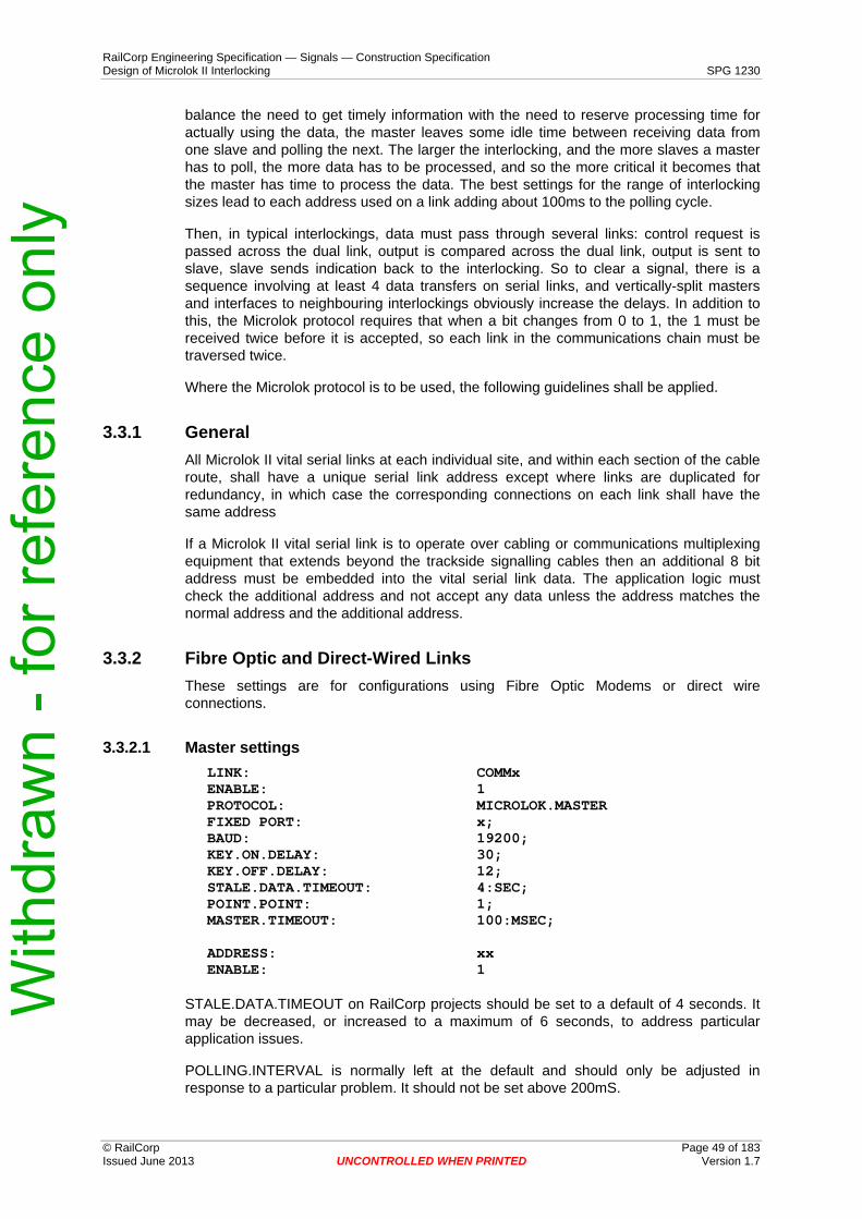
3.3 “Microlok” Vital Serial Links.....................................................................................................48 3.3.1 General ....................................................................................................................49 3.3.2 Fibre Optic and Direct-Wired Links..........................................................................49
3.3.3 Conversion between RS485 and RS232.................................................................50 3.3.4 Wiring.......................................................................................................................50
3.4 Genisys links (Control system link) .........................................................................................50 3.4.1 Slave........................................................................................................................51 3.4.2 Master ......................................................................................................................51 3.4.3 Conversion between RS232 and RS485.................................................................52 3.4.4 Wiring.......................................................................................................................52 3.4.5 Modem Configuration ..............................................................................................52
3.4.5.1 Leased Line Settings................................................................................53 3.4.5.2 Dial-up Settings ........................................................................................53
3.8 Control line states ...................................................................................................................57 3.8.1 RS232 Control Lines................................................................................................57 3.8.2 RS422/RS485 Control .............................................................................................57 3.8.3 RS423 Control .........................................................................................................57
4 Application Logic Design.....................................................................................................58 4.1 Introduction .............................................................................................................................58 4.2 Design Process .......................................................................................................................58 4.3 System Limitations ..................................................................................................................59
4.3.1 General ....................................................................................................................59 4.3.2 Object Controllers ....................................................................................................59
4.4 Standardisation of OCS Control of Interlockings ....................................................................60 4.4.1 Background..............................................................................................................60
With
draw
n - f
or re
fere
nce
only
RailCorp Engineering Specification — Signals — Construction Specification Design of Microlok II Interlocking SPG 1230
4.4.2 Applicability..............................................................................................................60 4.4.3 Elements of the OCS Philosophy ............................................................................60 4.4.4 Elements of the NX Philosophy ...............................................................................60 4.4.5 Changes to Interlocking Philosophy ........................................................................61 4.4.6 Further Enhancements to the Interlocking Philosophy............................................62 4.4.7 Variations between ATRICS and Phoenix Implementation .....................................62
4.5 General Guidelines .................................................................................................................63 4.5.1 Program Name ........................................................................................................63 4.5.2 Interlocking and Cardfile numbering........................................................................63 4.5.3 Naming Conventions ...............................................................................................64 4.5.4 Hot Standby .............................................................................................................64 4.5.5 Interface Section......................................................................................................64
5 Circuit Design........................................................................................................................87 5.1 Microlok II Design Configuration and Settings........................................................................87
5.1.1 Arrangements of Cards in Card Files ......................................................................87 5.1.2 Power Supply Card..................................................................................................87
5.1.2.1 Microlok II Power Consumption ...............................................................87 5.1.2.2 External Power Supply.............................................................................88
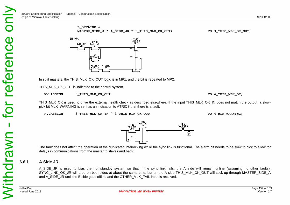
6.4 A Offline................................................................................................................................ 154 6.5 B Offline................................................................................................................................ 155 6.6 This Microlok OK.................................................................................................................. 156
6.6.1 A Side JR.............................................................................................................. 157 6.7 Online................................................................................................................................... 158 6.8 No Sync................................................................................................................................ 159 6.9 Enabling Outputs from the Master ....................................................................................... 159 6.10 Bypass.................................................................................................................................. 160 6.11 Serial Port Control Logic ...................................................................................................... 161 6.12 Serial Port Status logic......................................................................................................... 163 6.13 Intentionally deleted ............................................................................................................. 164 6.14 Synchronisation of Interlocking ............................................................................................ 164 Attachment A - Test Scenarios ........................................................................................................ 170 Test individual operation...................................................................................................................... 170 Test hot standby operation .................................................................................................................. 170 Superseded Data Structures ............................................................................................................ 172 Hot Standby Logic ............................................................................................................................... 172
With
draw
n - f
or re
fere
nce
only
RailCorp Engineering Specification — Signals — Construction Specification Design of Microlok II Interlocking SPG 1230
1.1 General The following documents provide supporting information or referenced information to that provided by this document.
1.1.1 Ansaldo STS Documents Ansaldo STS (formally Union Switch & Signal) is the designer and manufacturer of Microlok II and Microlok Object Controller. The following Ansaldo STS documents define the products and their use. They are referenced by this specification.
SM-6800A – Microlok II System Description SM-6800B – Microlok II Hardware Installation SM-6800C – Microlok II System Start up, Trouble Shooting and Maintenance SM-6800D – Microlok II System Application Logic Programming Guide SM-6800G – Microlok II Application Guidelines SM-6800K – Microlok II Network Protocol and Networking Hardware ML2-RS-007 – Microlok II Programmable Controller Platform Safety Application Issues SM-8584 – Microlok II Application Logic Comparison Tool SM-9494 – Microlok Object Controller Installation / Operation
1.1.2 RailCorp Documents The following table lists the RailCorp documents that are referenced by this specification.
SPG 705 - Construction of Cable Route and Associated Civil Works SPG 1013 – Cables for Railway Signalling Applications – Cable and Wire for indoor use SPG 1250 – Interfaces Between Signalling and Control Systems SPG 1856 – Environmental Conditions ESM 102 – Communications Outdoor cabling standard SPM 0677 - Single Mode Optical Fibre Cable SPM 1178 – Optical Fibre Termination, Patching and Management Equipment TMM P021 – Optic Fibre Cable Joining, Termination & Management TMG J038 – Microlok Computer Based Interlocking TMG G1232 – Microlok Interlocking simulation systems Design Guidelines TMG G1520 - Signalling Equipment Temperature Control Guidelines QSDP16 – Microlok File Control, Microlok Data Design and Factory Acceptance Test QSDP31 – Re-Testing of Microlok Data QSDP33 – Checking of Microlok Circuit and Data Designs QSDP48 – Signals Power Designs QSDP71 – Application of MISS, Replay and Emergency Control Software
Surge protection Installation Guideline LED signals controlled by relay circuits Design Guideline RailCorp Engineering Standards Design Guideline Aspect Controls and Indications in CBI Systems with Relay Interface
With
draw
n - f
or re
fere
nce
only
RailCorp Engineering Specification — Signals — Construction Specification Design of Microlok II Interlocking SPG 1230
The main body of this document provides generic information directly applicable to non-duplicated systems. For duplicated systems, refer to Appendix B “Hot Standby Arrangements” for modifications of the generic material.
With
draw
n - f
or re
fere
nce
only
RailCorp Engineering Specification — Signals — Construction Specification Design of Microlok II Interlocking SPG 1230
2.1 General This section details a set of design goals and methods of achieving the design goals when designing the system configuration for particular installations.
The signalling system configuration must comply with:
• The RailCorp Signalling Engineering Standards.
• The Microlok II manuals.
• Signalling design quality procedures.
• Signalling design guidelines.
2.2 Definitions
2.2.1 GeneralWhere the definitions given here differ from Signalling Equipment Configuration Standard ESG 003 or Computer Based Interlocking Requirements SPG 0719, the definitions here shall take precedence.
2.2.2 High Traffic areas High traffic areas are unidirectional Signalling with Headway Designs of less than 4 minutes or Bi-directional Signalling with Headway designs of less than 7 minutes in the normal running direction, and major junctions as listed in Critical Areas in ESG 003.
2.2.3 General Traffic areas General traffic areas are unidirectional Signalling with Headway Designs of less than 10 minutes or Bi-direction Signalling with Headway designs of less than 15 minutes, which do not come within the High traffic area definition.
2.2.4 Low Traffic areas Low traffic areas are all other areas that the High traffic and General traffic definitions do not apply.
2.3 Design goals
2.3.1 General• Clearly identified safety requirements and how they are achieved.
• Choose equipment with demonstrated level of reliability.
• The time delay from power on to the system being fully operational shall be less than 5 minutes.
• Provide facilities to permit disconnection of signalling equipment as per the Microlok Computer Based Interlocking Signalling Maintenance Procedure TMG J038.
With
draw
n - f
or re
fere
nce
only
RailCorp Engineering Specification — Signals — Construction Specification Design of Microlok II Interlocking SPG 1230
• Design to ensure independence of each line or minimise impact on adjacent lines.
• Common mode failure risks are identified and have a design solution implemented to address the risk.
• Provide duplication so that each single failure point will not cause more than one signalling object to fail except for items that can be demonstrated as "unlikely to fail within the expected life of the system".
• Provide duplication or separation for interlocking equipment at a set of points between lines so that hardware failure of signals will only fail one line.
• Design to ensure a single failure does not fail more than 2 signals on each line in each direction or have a fallback operational mode that can reduce the impact to equivalent to 2 failed signals in each direction.
• Provide a power supply system with two independent sources of supply that will also withstand loss of all incoming power for at least 10 minutes.
• Provide a power supply system that ensures breaks in supply to equipment are normally less than that required to disrupt the normal operation of the equipment. Some ancillary equipment may require supply breaks to be less than 20mS.
• All failures within the duplicated system to generate an alarm or warning or be revealed by maintenance task.
• Duplicated parts of the system are able to be isolated and have corrective action completed without disruption to train operations.
• All new works or alterations within the duplicated part of the system can be undertaken and tested without operational impact except for the final commissioning activities, which are minimised.
2.3.3 General traffic areas • Provide duplication for items that could cause a whole interlocking area to fail.
• Provide duplication for items that may require more than one maintenance team involved in corrective action or will take more than 2 hours to repair.
• Common mode failure risks are identified and managed in some way.
• Design to minimise single point failures that can impact on multiple lines.
• Design to ensure a single failure does not fail more than 2 signals on each line in each direction or have a fallback operational mode that can reduce the impact to equivalent to 2 failed signals in each direction.
• Provide a power supply system with two independent sources of supply that will also withstand loss of all incoming power for at least 1 minute.
• Provide a power supply system that ensures breaks in supply to equipment are normally less than that required to disrupt the normal operation of the equipment.
• All failures within the duplicated system to generate an alarm or warning or be revealed by a maintenance task.
• Duplicated parts of the system are able to be isolated and have corrective action completed without disruption to train operations.
2.3.4 Low traffic areas• Provide duplication for items that may require more than one maintenance team
involved in corrective action.
With
draw
n - f
or re
fere
nce
only
RailCorp Engineering Specification — Signals — Construction Specification Design of Microlok II Interlocking SPG 1230
• Provide a power supply system that will prevent a loss of power that will delay more than one train, under normal circumstances.
2.4 Power supply configuration
2.4.1 GeneralPower load calculations are to be as per Signal Design quality procedure QSDP 48 Signals Power Design.
2.4.2 High traffic areas Provide redundant supplies, and design to provide breaks of less than 10mS, with a standalone power supply capacity of 10 minutes or more. Components that are likely to fail within the life of the installation are to have redundant facilities as part of the design.
Normal and emergency supplies must be provided independently from the electricity grid.
Full galvanic isolation is required between each signalling location.
Power distribution should be at extended voltage (that is, higher than 120V).
The power system must detect “brown outs” in the normal supply and then use the other supply.
N+1 redundancy is required for all DC supplies other than track circuits, which may use non-redundant DC supplies as per normal practice.
DC power supplies are to be filtered and regulated. However existing unfiltered, un-regulated DC power supplies may be used for external inputs provided that Elsafe immunisation modules (216643) are fitted at the Microlok II inputs.
The Microlok II 12V supply is to be battery backed up as per the Microlok II manuals.
2.4.3 General traffic areas Supply breaks of up to 30 seconds can be tolerated but should normally be less than 0.1 seconds and occur less than once per 3 month period.
A standalone power supply capacity of 1 minute or more must be provided.
Normal and emergency supplies must be provided from independent sources. The Normal supply must be provided from the electricity grid and a railway supply is preferred.
The emergency supply should usually be provided from the electricity grid. The emergency supply may alternatively be automatically provided by generator, or battery with a 12 hour endurance minimum.
The power system must detect “brown outs” in the normal supply and then use the other supply.
N+1 redundancy is required for all DC supplies other than track circuits, which may use non-redundant supplies as per normal practice for DC supplies that will cause an immediate failure.
Choose approved DC power supplies with a Mean Time Between Failures (MTBF) of greater than 100,000 hours for those DC supplies that do not have redundancy.
With
draw
n - f
or re
fere
nce
only
RailCorp Engineering Specification — Signals — Construction Specification Design of Microlok II Interlocking SPG 1230
DC power supplies are to be filtered and regulated. However existing unfiltered, un-regulated DC power supplies may be used for external inputs provided that Elsafe immunisation modules (216643) are fitted at the Microlok II inputs.
The Microlok II 12V supply is to be battery backed up as per the Microlok II manuals.
2.4.4 Low traffic areas Supply breaks of up to 60 seconds can be tolerated but should normally be less than 10 seconds and occur less than once per month.
Normal supply can be from electricity grid or solar power. Solar power designs must have a minimum of 7 days autonomy.
Outside the electrified area the emergency supply may be provided by a motor generator, or battery with an 8 hour endurance minimum.
In some cases, not all equipment may be provided with emergency supply (eg point machines), however interlocking equipment must remain functional when operating from the emergency supply.
The power system must detect “brown outs” in the normal supply and then use the other supply.
No redundancy is required for DC supplies. Choose approved power supplies with an MTBF of greater than 100,000 hours.
DC power supplies are to be filtered and regulated. However existing unfiltered, un-regulated DC power supplies may be used for external inputs provided that Elsafe immunisation modules (216643) are fitted at the Microlok II inputs.
The Microlok II 12V supply is to be battery backed up as per the Microlok II manuals.
2.5 Interlocking equipment configuration
2.5.1 High traffic areas Fully redundant interlocking equipment with non–duplicated external circuits in a hot standby configuration is required.
Inputs from external equipment are commoned and wired to both Interlockings and OR’d together in the interlocking data.
Outputs are OR’d together via facilities to prevent the failure of one system affecting the loads, and to prevent output voltage on one side causing the other side to shutdown on an output diagnostics fault (ie stop “back feeds”).
Disconnection facilities must be provided for testing of new works and alterations without any impact on the operation of the railway.
Direct drive to LED signal lights is currently not permitted as this has the potential to cause the common mode failure of the interlocking equipment.
Individual interlockings may be split vertically if required due to processing constraints. The upper Microlok will process the inputs and interlocking controls to the system, and the lower will process the outputs and comparisons for synchronisation.
With
draw
n - f
or re
fere
nce
only
RailCorp Engineering Specification — Signals — Construction Specification Design of Microlok II Interlocking SPG 1230
Main interlocking equipment is duplicated in a hot standby configuration.
Interlocking equipment used to interface to track-side equipment does not need to be duplicated.
Direct drive to LED signal lights is not normally permitted as this can cause the failure of the interlocking equipment due to failures of the LED module, however would be permitted where such failures can be shown to be of an impact that fails not more than 2 signals on each track.
Individual interlockings may be split vertically if required due to processing constraints. The upper Microlok will process the inputs and interlocking controls to the system, and the lower will process the outputs and comparisons for synchronisation.
2.5.3 Low traffic areas The interlocking equipment does not require redundancy for availability.
Direct drive of LED signal lights is permitted. The interlocking design must provide a method to permit disconnection as per the Microlok Computer Based Interlocking Signalling Maintenance Procedure TMG J038.
2.5.4 Connection to adjacent interlockings For interlockings using the Peer to Peer protocol, the preferred connection arrangement for adjacent interlocking areas is to maintain separate ring networks for the two interlockings, with separate switches on each network in the interface location, and a duplicated connection between the two switches.
When interfacing a new Peer to Peer interlocking with an older Microlok installation, assuming the scope does not allow for a complete upgrade of the old interlocking to Peer to Peer, the preferred connection is to upgrade the boundary slave of the old interlocking to provide a peer connection to the new interlocking, in place of the existing relay (or other) interface. The non-preferred connection to an adjacent Microlok interlocking is via vital serial links from Slave Microloks at adjacent locations.
The interface between a Microlok II interlocking and another type of interlocking is via relay style interface circuits.
2.6 Control system communication link configuration
2.6.1 General Received data may need to be conditioned by the link status as the bit states are maintained when the link fails.
Communications links must have galvanic isolation between the interlocking equipment and any external circuits. Opto-isolators, or transformers are normally used to provide galvanic isolation. Some communications equipment provide galvanic isolation.
2.6.2 High traffic areas Two fully redundant communication links in constant use, with diverse paths, are to be provided.
With
draw
n - f
or re
fere
nce
only
RailCorp Engineering Specification — Signals — Construction Specification Design of Microlok II Interlocking SPG 1230
The communications equipment must use a secure no-break power supply. The communications links must not be disrupted for more than 15 seconds due to power supply disruptions.
Only point-to-point 19200 (preferred) or 9600 bps full duplex links should be used for main interlockings.
Multi-drop arrangements using Fibre Optic Modems for in-section signalling locations are acceptable, with a point to point link back to the Control System.
2.6.3 General traffic areas Two communication links are to be provided, a primary and a secondary. The secondary link does not need to be in constant use. If the secondary link is not normally in use then it must be brought into operation automatically, with less than a 90 second disruption to operations. The secondary link must be mostly via diverse path to the primary link. The secondary link must automatically re-establish if it fails whilst in service.
Non-continuous secondary links must automatically disconnect after more than 90 seconds of correct operation of the primary link.
The communications equipment must use a secure power supply. The communications links must not be disrupted for more than 30 seconds due to power supply disruptions.
Point to point 19200 (preferred) or 9600 bps full duplex links are preferred but Multi-drop 9600bps links may be used when point-to-point links are impractical.
2.6.4 Low traffic areas A single communication link is required with an MTBF of greater than 2 years. A secondary link is desirable. The operation of the secondary link does not need to be automated.
The communications equipment should use a secure power supply. The communications links must not be disrupted for more than 60 seconds due to power supply disruptions.
Point to point 19200, 9600 or 1200bps full duplex links are preferred but Multi-drop 9600bps or 1200bps links may be used when point-to-point links are impractical.
2.7 Safety system communication link configuration
2.7.1 General Peer to Peer communications are preferred for all vital serial communications.
Microlok master / slave communication links must not have any buffering or “store and forward” provided in the communications equipment between the Microlok II equipment as per the requirements set out in the Microlok II Platform Safety Application Guidelines. This prohibits transmission of Microlok protocol over Ethernet. The prohibitions do not apply to the Peer to Peer protocol, as it has mechanisms built-in to protect sequence of messages.
Typically “dark fibre” or a copper pair is provided and the approved Fibre Optic Modem arrangements, or analogue modems are provided as part of the signalling installation.
Communications links must have galvanic isolation between the interlocking equipment and any external circuits. Opto-isolators or transformers are normally used to provide galvanic isolation. Some communications equipment provides galvanic isolation.
With
draw
n - f
or re
fere
nce
only
RailCorp Engineering Specification — Signals — Construction Specification Design of Microlok II Interlocking SPG 1230
Particular configuration details are set out in the section on Serial links.
2.7.2 High traffic areas No single equipment or cable failure shall cause an operational impact on the railway.
Fibre Optic communications links must be used between locations.
Duplicated point to point links do not require a diverse link but they must have some physical diversity in the links.
Multi-drop links for slaves in more than 5 separate locations must have a loop arrangement with a redundant link. RS400/RS900 switches are capable of managing a diverse fibre Ethernet link. Diversity Link Controllers (DLC) are used for vital serial links.
For interlockings using the Microlok vital protocol, no more than 10 slave addresses are to be used on one link. Using Fibre Optic modems at 19200bps, this results in a poll cycle time of about 900mS for the link (about 90ms per slave). There is no need to limit slaves due to communications timing when using the Peer to Peer protocol.
2.7.3 General traffic areas Single equipment, or cable failure can cause an operational impact on the railway.
Facilities must be provided so that the Signalling maintenance personnel can correct the failure without other assistance.
Fibre Optic communications links must be used.
Duplicated point to point links do not require a diverse link but they must have some physical diversity in the links.
Multi-drop links for slaves in more than 9 separate locations must have a loop arrangement with a redundant link. RS400/RS900 switches are capable of managing a diverse fibre Ethernet link. Diversity Link Controllers (DLC) are used for vital serial links.
For interlockings using the Microlok vital protocol, no more than 12 slave addresses are to be used on one link. Using Fibre Optic modems at 19200bps, this results in a poll cycle time of about 1080mS for the link (about 90ms per slave). There is no need to limit slaves due to communications timing when using the Peer to Peer protocol.
2.7.4 Low traffic areas No redundancy for availability is required.
Single equipment, or cable failure may cause an operational impact on the railway.
Fibre Optic communications links should be used for complete new installations. Modem links using copper cables are acceptable when new cable routes are not being provided.
The poll cycle time must be less than 2 seconds.
2.8 Equipment housing and cable route configuration
2.8.1 General Equipment housings and cable routes must comply with specification alterations identified in the Proposal for Standard Specification alterations to address issues with 415V
With
draw
n - f
or re
fere
nce
only
RailCorp Engineering Specification — Signals — Construction Specification Design of Microlok II Interlocking SPG 1230
signalling power distribution, Surge protection installation guideline, and the Ancillary Equipment Temperature rating Installation guideline.
Passive temperature control is required on all locations, using a method of shade structures or “double skinning” and adequate ventilation.
Positioning of any location must consider:
• Protection of the location from damage.
• 1 in 100 year flooding.
• Fire risk.
• Surge damage risk.
• Damage due to High voltage power faults.
Location layout must provide:
• Segregation for wiring and equipment for surge protection.
• Layout of equipment and wiring to minimise coupling of electrical noise onto sensitive circuits.
• Layout of equipment for ease of maintenance.
• Layout of equipment for temperature effects.
2.8.2 High traffic areas As well as complying with the RailCorp Signalling Engineering standards requirements for protecting against fire damage and stopping the spread of fire, the limiting of fire damage should be considered in the design.
Passive fire protection should be provided so that cable routes can withstand an external fire without irreparable damage as per the Environmental Conditions SPG 1856.
Routing of cable routes is to consider surge protection issues and proximity to High Voltage Earths for Earth Potential Rise (EPR) issues.
Duplicate cables or diverse cables must be physically separated or have appropriate physical protection so that it is improbable that both cables are damaged in the one incident.
Cables that can introduce significant surges must not be placed in close proximity to other cables prior to having passed through some surge protection.
A re-enterable cable route is required.
2.8.3 General traffic areas Passive fire protection should be provided so that cable routes can withstand an external fire without irreparable damage as per the Environmental Conditions SPG 1856.
2.8.4 Low traffic areas There are no additional requirements for Low traffic areas. W
ithdr
awn
- for
refe
renc
e on
ly
RailCorp Engineering Specification — Signals — Construction Specification Design of Microlok II Interlocking SPG 1230
2.9.1 GeneralWith the exception of prefixes in the application data to designate bits as inputs or outputs and use of underscores in data in place of spaces, the names of inputs and outputs as shown in circuit books shall match the names of bits used within the application. In the case of outputs driving relays (whether directly or through isolation modules), the relay name and the output name shall be the same.
Microlok application data must not use Look-up tables or Coded Outputs (coded track circuits excepted) without a specific design guideline being approved for the particular use.
Microlok application data must not use Numeric blocks – including the Real Time Clock – for purposes other than configuration control without a specific design guideline being approved for the particular use.
External signalling circuits driven by Microlok Outputs must not have “stick” paths without a design review to confirm that short duration “false” outputs do not cause a hazard.
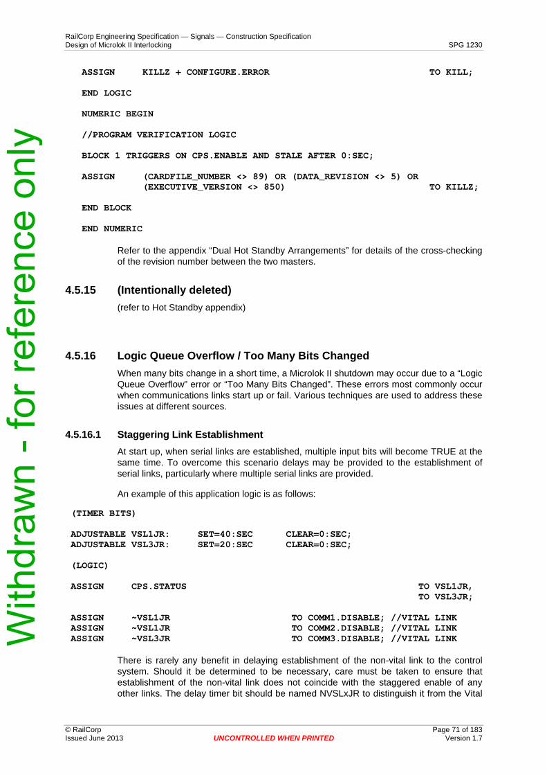
The self-checking techniques used on vital outputs may allow a vital output to remain falsely “on” for up to one second. This is the main reason for the continued use of the IR for points control – two outputs are required to operate the points. For maximum safety assurance, the IR should not be driven from the same output card as the NWR/RWR. In small locations where only a single output card is required, Outputs 1 to 8 and 9 to 16 may be considered as separate groups for error checking purposes, and the NWR/RWR wired from one group, and IR from the other.
The LOGIC_TIMEOUT default setting of 2 seconds must be used unless there is a specific problem. It may be set to no more than 4 seconds to address the problem. If this is not satisfactory then other solutions must be found.
The DELAY_RESET default setting is 100mS. It should not normally be changed. It may be set at any value in the provided range to address a particular problem.
The RESET, QUICK.RESET system bits are not to be set by the application logic. The KILL system bit should be used instead.
The SELECTIVE.SHUTDOWN bits for the boards are not to be set by the application logic.
Timers less than 24 seconds can be delayed by more than 10% of their value. Consideration must be given to the impact of delays when using timers of less than 24 seconds. This may cause problems with timers used for speed control.
All direct vital output circuits must be powered via a contact of the VCOR or a repeat of the VCOR.
Safety critical faults detected by the application logic must set the KILL system bit. This shall include the CONFIGURE.ERROR bit. Object Controllers CONFIGURE.ERROR bit is set whenever the EEPROM configuration is invalid. It is clear when the EEPROM configuration matches the Application data CRC installed on the Object Controller unit. The following line must be included in the Application data for the Object Controller.
ASSIGN CONFIGURE.ERROR TO KILL;
Vital serial links are to be disabled by the loss of the CPS.STATUS system bit.
With
draw
n - f
or re
fere
nce
only
RailCorp Engineering Specification — Signals — Construction Specification Design of Microlok II Interlocking SPG 1230
It is not necessary to fail a coded track circuit on loss of the CPS.STATUS system bit, however action is to be taken to ensure that track codes are not able to allow a potential safety hazard due to the event that caused the CPS.STATUS to become false.
The Microlok 12VDC power supply shall not normally be used for circuits that run outside the signalling equipment location or room in a building. Permitted exceptions are:
1 Direct drive of Signal lights via the Vital Lamp Driver card N17060101.
2 Non Vital Non Isolated input and output card circuits for up to 20m long with specific approval of the Chief Engineer Signals and Control Systems.
3 Non Vital Isolated input card circuits less than 20m long for inputs from adjacent electrical power rooms/locations
No exception is given for Non Vital isolated input and isolated output card circuits which must use a separate power supply if they are to run external to the location/building.
External circuits using the Microlok 12VDC must run in cables contained in a cable route according to SPG 705 Construction of Cable Route and Associated Civil Works.
2.9.2 Approved Items
2.9.2.1 Microlok II
Part Number Description
Permitted for High Traffic use(See Note)
Permitted for General Traffic use (See Note)
Permitted for Low Traffic use (See Note)
See Note
N17061301 Central Processing Unit 1 & 11
N800101-0001 Microlok II Executive Software Version 8.50
2
N800102-0001 Microlok II Development System V8.50
3
N16661203 Power Supply 4
N451910-7501 CPS card
N17060101 Vital Lamp Driver Card Limited
Usage 5
N17060501 Standard Vital Output (12V) 6 & 15
N17066801 Second Generation Standard Vital Output (12V)
15
N17061001 Vital Input (12V) Limited Usage
7
N17061003 Vital Input (50V) 7
N17061501 Non Vital Non Isolated Input and
Limited usage
Limited usage
8
With
draw
n - f
or re
fere
nce
only
RailCorp Engineering Specification — Signals — Construction Specification Design of Microlok II Interlocking SPG 1230
N17061601 Standard 8 Vital Output, 8 Vital Input (12)
Permitted
but not preferred
N17062701 Non Vital Isolated Output Card
N17063701 Non Vital Isolated Input Card
N451910-0701 Microtrax Coded Track Circuit PCB 9
N17001102 Output Isolation Module (50V)
10
J703105-0107 4MB FLASH Card 11
N322500-701 VCOR relay PN-150B (6FBSTD) 400 ohm
N322505-701
VCOR relay PN-150HD (4FBHD/2FBSTD) 400 ohm
12
N451376-0302 Plug-in base for PN-150B & PN-150HD relays
13
N16902101 General purpose card file 14
N16905301 Dual card file 14, 16
N18003901 Half box card file 14
N451850-2902 1-wide blank front panel
N451859-2901 2-wide blank front panel
Notes
1 Where available, one spare serial port on masters is to be wired out to interface terminals or a suitable connector.
2 Previously approved Executive Versions 3.2, 3.4, 4.01, and 5.1 are approved for minor alterations at existing locations but are not to be used on new installations. Major alterations should upgrade to V8.50.
3 Includes the Compiler, Reverse Compiler and Comparison Tool as well as Microlok II Development System.
4 This is the Enhanced Power Supply card, launched by Ansaldo STS as a direct replacement for the old N16660301. The Enhanced card has higher current capacities compared to the old card: 5VDC @ 5A (up from 3A), -12VDC @ 2A (up from 1A), +12VDC @ 1A (unchanged). This may eliminate the need for
With
draw
n - f
or re
fere
nce
only
RailCorp Engineering Specification — Signals — Construction Specification Design of Microlok II Interlocking SPG 1230
external power supplies in some projects. When using the Power Calculation tool in the Microlok Tools software, designers should note that version 5.1 (and earlier) calculators do not allow for the higher capacity of the Enhanced Power Supply. Version 8.5 Tools show current loads for both versions of the Power Supply card.
5 Spare outputs may be wired to interface terminals. All lamps outputs are to meet the requirements for disconnection as per the Microlok Computer Based Interlocking Signalling Maintenance Procedure TMG J038. If the usage is limited then use of the card is permitted based on failure impact meeting the design goals.
6 Spare outputs shall preferably be left unwired. Where future stages will require additional outputs, spare outputs may be wired to interface terminals, and such outputs must be terminated with 220R 1W resistors. All outputs that are wired are to be wired via a disconnect terminal (between the Microlok and the relay or other output load) to permit disconnection as per the “Disconnection of Signalling Apparatus” Signalling Maintenance Procedure. For locations with duplicated outputs, removable diode plugs are acceptable disconnection points.
7 Spare inputs may be wired to interface terminals if required for future stages.
8 Care is required in allocating the N12 connections. The input circuits should use A13, C3, C13, C12 as the N12 connections. The output circuits should use A17, A21, A25, A29 as the N12 connections.
9 This module is for use in permitted non-electrified areas only. The application data is to contain 75% of the actual track length or a value set by the Engineer certifying the track as the default.
10 The isolation module is to be provided with 15V power to ensure the output voltage is adequate.
11 Top PCMCIA Programming Voltage on JMP28 set to program and the Flash Programming Voltage on JMP30 - set to 5 volts.
12 Used in conjunction with Vital Lamp Driver Card.
13 Use the M451142-2702 contact springs associated with this relay base.
14 This includes items detailed in Ansaldo STS document SM-6800B Section 4.2.3 PCB Interface Cable Assembly Components and Tools as well as Sections 4.2.4 Misc. Cardfile Installation Parts as limited by this specification.
15 The second generation standard output is preferred for new designs. All OUT16 modules at a location are to be the same type. When using the Power Calculation tool, note that the second generation OUT16 card draws approximately twice the current of the original OUT16 card.
16 The Dual Card File (also referred to as Split Card File) is not to be used to house both 'sides' of a duplicated installation. To do so would reduce the benefit of duplication – a fault on the backplane of one side requires that both sides be shut down to replace the card file. With
draw
n - f
or re
fere
nce
only
RailCorp Engineering Specification — Signals — Construction Specification Design of Microlok II Interlocking SPG 1230
N800701-0001 Microlok Object Controller Executive Version CC 1.0
1
N800706-0001
Microlok Object Controller Network Diagnostic Tool Version CC 1.10
1
N800114-0001
Microlok Object Controller Maintenance Tool Version CC 1.10
2
N18400801 Software Keying Module (dongle) for Object Controller
1
N16929801
Write enable adapter for Software Keying Module.
1
N17001101 Output Isolation Module (12V)
N34800901
Input Isolation Module
Notes
1 Qualified Signalling Type Approval until in-service reliability demonstration is completed. Specific approval of the Chief Engineer Signals and Control Systems is required for use on a project.
2 The Microlok Object Controller Maintenance Tool includes the Compiler, Reverse Compiler and Application Comparison Tool. All with consistent versions.
2.9.3 Timers in High traffic areas Timers set for less than 24 seconds must be reviewed to determine that they will not cause an operational impact or safety hazard if they are delayed by more than 10%.
2.9.4 Timers in General traffic areas Based on the lower expected rail traffic conditions Timers set for less than 12 seconds must be reviewed to determine that they will not cause an operational impact or safety hazard if they are delayed by more than 10%.
With
draw
n - f
or re
fere
nce
only
RailCorp Engineering Specification — Signals — Construction Specification Design of Microlok II Interlocking SPG 1230
Based on the lower expected rail traffic conditions Timers set for less than 6 seconds must be reviewed to determine that they will not cause an operational impact or safety hazard if they are delayed by more than 10%.
2.9.6 Microlok Interlocking Simulator Systems Testing of the interlocking shall be performed on a Microlok Interlocking Simulation system, which is to be configured in accordance with TMGG 1232 Microlok Interlocking simulation System (MISS) Design Guidelines. Microlok data, communications links, and MISS facilities and files shall be in accordance with QSDP 71 Application of MISS, Reply and Emergency Control software. This is to ensure that MISS files are suitably controlled and that the trackside screens and control screen may be directly used for the replay and local control, if required.
2.10 Microlok Object Controller
2.10.1 GeneralThe Object Controller is a product range of compact vital logic processors, available in various pre-assembled configurations for different input/output arrangements. RailCorp projects shall be standardised on a single version – Object Controller 2005, Ansaldo STS part number N17700119. It features 12 vital inputs, 12 vital outputs, 2 Ethernet communications ports, 1 Ethernet diagnostics port and a DB9 connector for the Software Keying Module.
Network configurations are not to use Power Over Ethernet or Power from Switch options.
Terminals on Signalling interfaces connectors J1, J2, J3, J4 identified as "NO CONNECT" shall not have any external wiring. These are terminals 13 to 16 on J1 and J3 as well as terminals 5 to 8 on J2 and J4.
2.10.2 Power supply A no break power supply arrangement is required. This may be provided by either a no break AC power supply or using a float charged battery as per the Microlok II arrangements.
The DC power supply shall provide for at least 3A per Object Controller.
Where no break AC power is provided, typically the same power supply arrangement as Microlok II is provided without the battery.
Wiring from the 12VDC power supply to the Object Controllers must be controlled to limit ripple on the voltage supplied to Object Controllers. Wire with a size less than 1.5mm2 that is used between the power supply and the Object Controller shall have a loop length less than 10m.
2.10.3 Outputs Unlike Microlok II output cards, the Object Controller directly drives output loads from the isolated Conditional Power Supply, thereby requiring no external VCOR. The total power supply capacity, and load current of each output, is limited. Each output can drive a single 12V QN1 relay or a single 12V QS2 relay. The total of all loads driven simultaneously
With
draw
n - f
or re
fere
nce
only
RailCorp Engineering Specification — Signals — Construction Specification Design of Microlok II Interlocking SPG 1230
must not exceed 500mA. QBCA1 12V relays are not permitted to be directly driven by an Object Controller.
The following combinations of output relay loads are permissible:
Up to six QS2 6-6 500 ohm 12V relays. Preferred option.
Up to four 12V QN1 relays.
Up to three 12V QN1 relays and three 12V QS2 relays
An Output Isolation module (12V) can be driven by the Object Controller as an equivalent load to a 12V QS2 relay. The Output Isolation module (12V) is accepted for driving a QBCA1 12V relay.
Bi-polar output arrangements are not permitted.
2.10.4 Signalling interface connectorsWAGO MCS-MIDI style connectors are used for the input, output and power connectors for the Object Controller. Inputs use female 16 pole orange WAGO connectors with a pin spacing of 5.08mm. Outputs use female 16 pole gray WAGO connectors with a pin spacing of 5.0mm. The power terminal uses a female 4 pole orange WAGO connector with a pin spacing of 5.08mm.
The male headers inside the Object Controller have coding pins attached to them. They are used to prevent the inputs and outputs from being incorrectly terminated.
The inputs and output connectors, along with their cables shall be clearly labelled.
The WAGO input and output connectors shall have numbering applied.
Strain relief plates and connectors that come pre-numbered in the factory are available. Two options are available when ordering replacement parts. The preferred option is to order the factory numbered connectors with the strain relief plates pre-assembled, refer to Section 2.10.4.1 for part numbers. The second option is to buy the numbered connector and strain relief plates separately, refer to Section 2.10.4.2 for part numbers.
2.10.4.1 Factory Assembled WAGO Connectors with Strain Relief Plates
WAGO Item Number Description Important Note
16 Pole gray female connector with 5mm pin spacing, locking levers, When ordering, specify
231-116/037-047/035-000 direct printing of numbers and numbering of 1 to 16 starting preassembled 50mm strain relief from right side to left side. plate. Used for Outputs.
16 Pole orange female connector with 5.08mm pin spacing, locking When ordering, specify
231-316/037-047/035-000 levers, direct printing of numbers numbering of 1 to 16 starting and preassembled 50mm strain from right side to left side. relief plate. Used for Inputs.
With
draw
n - f
or re
fere
nce
only
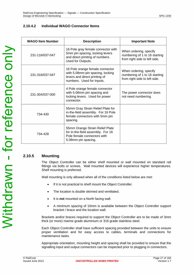
RailCorp Engineering Specification — Signals — Construction Specification Design of Microlok II Interlocking SPG 1230 2.10.4.2 Individual WAGO Connector Items
16 Pole gray female connector with 5mm pin spacing, locking levers and direct printing of numbers. Used for Outputs.
When ordering, specify numbering of 1 to 16 starting from right side to left side.
231-316/037-047
16 Pole orange female connector with 5.08mm pin spacing, locking levers and direct printing of numbers. Used for Inputs.
When ordering, specify numbering of 1 to 16 starting from right side to left side.
231-304/037-000
4 Pole orange female connector with 5.08mm pin spacing and locking levers. Used for power connector.
The power connector does not need numbering.
734-430
55mm Gray Strain Relief Plate for in-the-field assembly. For 16 Pole female connectors with 5mm pin spacing.
734-428
55mm Orange Strain Relief Plate for in-the-field assembly. For 16 Pole female connectors with 5.08mm pin spacing.
2.10.5 Mounting The Object Controller can be either shelf mounted or wall mounted on standard rail fittings via bolts or screws. Wall mounted devices will experience higher temperatures. Shelf mounting is preferred.
Wall mounting is only allowed when all of the conditions listed below are met:
• If it is not practical to shelf mount the Object Controller.
• The location is double skinned and ventilated.
• It is not mounted on a North facing wall.
• A minimum spacing of 10mm is available between the Object Controller support bracket / brace and the location wall.
Brackets and/or braces required to support the Object Controller are to be made of 3mm thick (or more) marine grade aluminium or 316 grade stainless steel.
Each Object Controller shall have sufficient spacing provided between the units to ensure proper ventilation and for easy access to cables, terminals and connections for maintenance tasks.
Appropriate orientation, mounting height and spacing shall be provided to ensure that the signalling input and output connectors can be inspected prior to plugging in connectors.
With
draw
n - f
or re
fere
nce
only
RailCorp Engineering Specification — Signals — Construction Specification Design of Microlok II Interlocking SPG 1230
Spacing is required between Object Controllers to ensure that the Software Keying Modules cannot be cross connected.
2.10.6 Object Controller Software Keying Module The Software Keying Module is based on a EEPROM that has a serial interface to the Microlok Object Controller. Naming of the Software Keying Module is not consistent in the Ansaldo STS documentation with various names like serial dongle, EEPROM dongle and dongle also being used.
The use of the Software Keying module ensures that the correct site specific Application data has been installed on the Object Controller. An Object Controller will only start with the CPS in the UP state if its Application data corresponds with the information stored on the attached Software Keying Module.
The Software Keying Module is permanently fixed at a Signalling equipment location and is positioned adjacent to the corresponding Object Controller unit. The fixing of each Software Keying Module shall ensure that it can only be plugged into its designated Object Controller.
The Software Keying Module must be updated whenever changes are made to the Application data. The Write Enable adapter (N16929801) from Ansaldo STS is used during the update process.
The ‘Network Diagnostic Tool’ is used to write and update the Software Keying Module. This is a web based tool that runs on Internet Explorer web browser. Refer to the Ansaldo STS EEPROM dongle update procedure for a detailed description of the writing and updating procedure for the Software Keying Module.
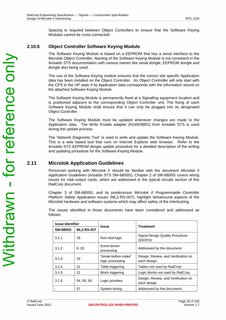
2.11 Microlok Application GuidelinesPersonnel working with Microlok II should be familiar with the document Microlok II Application Guidelines (Ansaldo STS SM-6800G). Chapter 2 of SM-6800G covers wiring issues for vital output cards, which are addressed in the typical circuits section of this RailCorp document.
Chapter 3 of SM-6800G, and its predecessor Microlok II Programmable Controller Platform Safety Application Issues (ML2-RS-007), highlight behavioural aspects of the Microlok hardware and software systems which may affect safety of the interlocking.
The issues identified in those documents have been considered and addressed as follows:
Issue Identifier Issue Treatment
SM-6800G ML2-RS-007
3.1.1 18 Non-vital logic Signal Design Quality Procedure QSDP33
3.1.2 9, 20 Event-driven processing
Addressed by this document.
3.1.3 19 “break-before-make” logic processing
Design, Review, and Verification on each design.
3.1.4 22 Table triggering Tables not used by RailCorp
3.1.5 21 Block triggering Logic blocks not used by RailCorp
3.1.6 54, 55, 56 Logic priorities Design, Review, and Verification on each design.
- 57 System timing Addressed by this document.
With
draw
n - f
or re
fere
nce
only
RailCorp Engineering Specification — Signals — Construction Specification Design of Microlok II Interlocking SPG 1230
Not currently approved for direct drive by Microlok II Vital Lamp Driver card.
United
The Mark 2 Outdoor 212mm, DC signal light requires a 24R, 25W WH25 series resistor fitted in the signal head when operated using a regulated 16.2V lamp supply.
• Up to 110m cable distance using 1.5mm2 of twisted pair cable using regulated 16.2V lamp voltage.
• Up to 340m cable distance using 4mm2 of twisted pair cable using regulated 16.2V lamp voltage.
The Mark 2 Outdoor 212mm, DC signal light requires a 15R, 25W WH25 series resistor fitted in the signal head when operated using an un-regulated 13.6V battery supply.
• Up to 20m cable distance using 1.5mm2 of twisted pair cable using 13.6V battery supply as the lamp voltage.
• Up to 60m cable distance using 4mm2 of twisted pair cable using 13.6V battery supply as the lamp voltage.
The Mark 2 Outdoor 127mm, DC signal light requires a 12R, 25W WH25 series resistor fitted in the signal head when operated using a regulated 16.2V lamp supply.
• Up to 110m cable distance using 1.5mm2 of twisted pair cable using regulated 16.2V lamp voltage.
• Up to 340m cable distance using 4mm2 of twisted pair cable using regulated 16.2V lamp voltage.
The Mark 2 Outdoor 127mm, DC signal light requires a 10R, 25W WH25 series resistor fitted in the signal head when operated using an un-regulated 13.6V battery supply.
• Up to 40m cable distance using 1.5mm2 of twisted pair cable using 13.6V battery supply as the lamp voltage.
• Up to 110m cable distance using 4mm2 of twisted pair cable using 13.6V battery supply as the lamp voltage.
The DC LED stencil indicator requires a 10R, 50W WH50 series resistor fitted in the signal head.
• Up to 110m cable distance using 1.5mm2 of twisted pair cable using regulated 16.2V lamp voltage.
• Up to 340m cable distance using 4mm2 of twisted pair cable using regulated 16.2V lamp voltage.
• Up to 20m cable distance using 1.5mm2 of twisted pair cable using 13.6V battery supply as the lamp voltage.
• Up to 60m cable distance using 4mm2 of twisted pair cable using 13.6V battery supply as the lamp voltage.
With
draw
n - f
or re
fere
nce
only
RailCorp Engineering Specification — Signals — Construction Specification Design of Microlok II Interlocking SPG 1230
The RM4 series outdoor, 212mm signal light requires a 15R, 25W WH25 series resistor fitted in the signal head.
• Up to 160m cable distance using 1.5mm2 of twisted pair cable using regulated 16.2V lamp voltage.
• Up to 450m cable distance using 4mm2 of twisted pair cable using regulated 16.2V lamp voltage.
• Up to 55m cable distance using 1.5mm2 of twisted pair cable using 13.6V battery supply as the lamp voltage.
• Up to 160m cable distance using 4mm2 of twisted pair cable using 13.6V battery supply as the lamp voltage.
The TR3 501 series tunnel or outdoor 127mm signal light requires a 10R, 25W WH25 series resistor fitted in the signal head.
• Up to 160m cable distance using 1.5mm2 of twisted pair cable using regulated 16.2V lamp voltage.
• Up to 450m cable distance using 4mm2 of twisted pair cable using regulated 16.2V lamp voltage.
• Up to 40m cable distance using 1.5mm2 of twisted pair cable using 13.6V battery supply as the lamp voltage.
• Up to 110m cable distance using 4mm2 of twisted pair cable using 13.6V battery supply as the lamp voltage.
2.12.1.2 Relay control Relay control of LED signals must be as per the LED signals controlled by relay circuits Design Guideline.
2.12.2 Track Circuits Track circuit limits are as per the RailCorp Signalling Engineering Standards.
2.12.3 Microtrax Coded Track Circuits The cable from the location to the Microtrax Coded track, track interface unit must be less than 50m of 1.5mm2 twisted pair cable, or 150m of 4mm2 twisted pair cable unless a technical review is performed which determines an acceptable feed length for the particular Coded track circuit.
Microtrax Coded track circuits shunting sensitivity is affected by the loop resistance of the cable from the location to the trackside interface unit. The importance of the loop resistance increases as the length of the track increases.
The track interface panel must have RSA disconnect links on the connections to the rails to allow for disconnection as per TMG J038 Microlok Computer Based Interlocking Signalling Maintenance Procedure and TMG J037 Microtrax Signalling Maintenance Procedure.
A 0R22 resistor in the track interface unit is typically fitted in the trackside of the Track Interface unit to decrease the shunting sensitivity to at least 0.25 ohms.
A 0.25 ohm test shunt is used in certifying the Microtrax Coded Tracks.
With
draw
n - f
or re
fere
nce
only
RailCorp Engineering Specification — Signals — Construction Specification Design of Microlok II Interlocking SPG 1230
2.12.4 Relay noise suppression Relays generate electrical noise when they are de-energised. This electrical noise can interfere with electronic or computerised equipment like the Microlok II.
The recommendation in Microlok II manual SM-6400B to use Transorbs is not preferred, as these units have been found to be un-reliable.
Relays that are controlled by a circuit that is exclusively within the location housing the relay are snubbed with a 1N4007 diode fitted in the reverse direction across the coil. This method is suitable for 12VDC, 24VDC, and 50VDC relays only, and generally cannot be used where a pair of biased relays are used on a polarised detection circuit (however the parallel biased coils tend to snub each other). This use of a diode for snubbing has been found to be the most effective method.
Fitting the diode across the relay coil defeats AC immunity. For this reason, relays that are controlled by a circuit that is not exclusively within the location housing the relay are snubbed with a Contact suppressor (RC snubber 0.1uF plus 100R) fitted across the coil. These units are suitable for 12VDC, 24VDC, 50VDC relays. They may be used for 120VAC relays but this will operate the RC snubber at close to its 0.5W power rating. They are available from RS Components as stock number 206-7881 for free wiring.
In some cases a resistor can also be used for snubbing purposes, this will normally be for an AC circuit.
Relays directly driven by Microlok II must be snubbed.
All relays at a location with Microlok II are to be snubbed or the Microlok II segregated from the source of the electrical noise. The preferred method of segregation is by the use of twisted pair wiring, AC Immunising modules on the inputs, and Microlok II Isolation modules or relays on the outputs and physical separation.
2.12.5 Input circuits Safety critical inputs for Microlok II and Microlok Object Controller require immunity from sources of 50Hz AC, traction currents, and general electrical noise as well as surges due to lightning.
Input circuits that are wholly within a tunnel and do not travel within 100m of the tunnel portal do not require the surge protection.
The surge protection arrangement must also consider 50Hz Earth Potential Rise (EPR) faults if both ends of the circuit are not at the same location.
Input circuits shall be double cut and use twisted pair wiring in the location.
Bi-polar input arrangements may be used.
Input circuits that remain within the signalling equipment room/location for installations that have all signalling relays snubbed do not require surge protection or noise filtering.
Input circuits that run outside the signalling equipment room/location and for installations that have un-snubbed signalling relays require noise filtering by Elsafe modules 216643 for 50VDC circuits or 216630 for 12VDC circuits. The Elsafe modules shall be located near to the Microlok or Object Controller. The wiring from the Elsafe modules to the W
ithdr
awn
- for
refe
renc
e on
ly
RailCorp Engineering Specification — Signals — Construction Specification Design of Microlok II Interlocking SPG 1230
Microlok or Object Controller shall be segregated form wiring exposed to significant sources of electrical noise.
External circuits for inputs that use Instrolex (formerly Dekoron – see footnote1) twisted pair cable are permitted for up to the following acceptable two wire circuit lengths:
• 4,000m for the 50V input card. • 400m for the 12V input card or Object Controller.
External circuits for inputs that use traditional signalling cable are permitted for up to the following acceptable two wire circuit lengths:
• 3000m for the 50V input card. • Not accepted for 12VDC circuits.
Extended input circuit arrangement can be accepted in special cases where that arrangement provides a significant benefit. The arrangement can be from 3 to 8km for Signalling multi-core cable using adjacent cores in the same layer of a cable. The supply for the inputs must be a filtered, regulated power supply set to a nominal 54VDC. Core allocation changes due to maintenance must keep the arrangement. A specific approval is required from the Chief Engineer Signals and Control Systems for extended input circuit arrangements.
If a single 50VDC supply feeds both internal Microlok inputs and Microlok inputs via external circuits, then either the internal Microlok inputs must have Elsafe 216643 modules fitted or a filter arrangement provided for the power supply.
2.13 Cables and wiring
2.13.1 Colour codingGenerally black wire is used for permanent control wiring. The Power supply wiring colour code is red for positive DC, Black for Negative DC, and Blue for un-earthed AC.
Paired cables or wires for control wirings will normally have black and white as a pair. The white is to be used for the negative or neutral side of the circuit, and black as the Positive or Active side of the circuit.
Some paired cables or wires for control wirings have red and black pairs. The black is used for the negative or neutral side of the circuit, and the red as the positive or active side of the circuit.
2.13.2 General multi-core cable CBI interface applications may use Olex Instrolex Instrumentation cable with an overall screen for signalling inputs and outputs. The cable must have a nylon jacket and a sacrificial PVC sheath added to the standard cable.
The standard Instrolex cables are twisted pair cables and need to be used as pairs to provide immunity to electrical noise and interference. These cables are permitted for use at voltages up to 130VAC or 150VDC/. Circuit currents should not normally exceed 6 amps, which is half the Manufacture’s rated current.
1 New works should not refer to Dekoron. The Dekoron name may in future be applied to a different product range.
With
draw
n - f
or re
fere
nce
only
RailCorp Engineering Specification — Signals — Construction Specification Design of Microlok II Interlocking SPG 1230
2.13.3 Internal Wire Safety critical wiring in Location cases and Relay Rooms where a Computer Based Interlocking system is being used must use ETFE Teflon insulated wire for interface wiring due to problems with the thickness of insulation and the possibility of leaking plasticiser from the nylon jacketed PVC wire. The wire is specified in RailCorp Engineering Standard SPG 1013 Cables for Railway Signalling Applications - Single Conductor Cables for Indoor Use. It also available as black and white twisted pair. Twisted at greater than 15 twists per metre.
The wire is 19/29 AWG, 1.23mm2 It is accepted for termination in general terminals, the 48 way connectors for the Microlok II card file, and Q relay crimps.
For 48 way connectors, use twisted pair black & white cable 19/29 AWG, 1.23 mm2 wires with Harting Part No. 09-06-000-8472 crimps.
The Microlok II CPU 48 way connectors also need connections for serial links. Typically 24 AWG Cat 5 cable is used with Harting Part No. 09-06-000-8471 crimps.
For 96 way connectors, use black 19/34 AWG, 0.4 mm2 wire with Harting Part No. 09-02-000-8474 crimps.
The approved interface terminals for duplicated arrangements uses Weidmuller ZTR2.5 series.
The dual input terminal arrangement consists of 2 x ZTR2.5 Weidmuller terminals (Order number 1831280000) with 1 x ZQV2.5/2 cross connection (Order number 1608860000).
The dual outputs terminal arrangement consists of 2 x (ZTR2.5/O.TNHE plus BEST/D connector) Weidmuller terminals with 1 x ZQV2.5/2 cross connection. Order numbers are: terminal base ZTR2.5/O.TNHE (1831130000 ); 1N4007 diode connector BEST/D (1878560000) and 2 way cross connect (1608860000).
2.13.7 Patch leads Category 5 (or better) UTP patch leads using 4 pair 24AWG conductors with gold plated RJ45 connectors terminated to T568B standard at both ends shall be used.
Leads with moulded strain relief on the connectors and the snag less feature are preferred. If moulded strain relief is provided on the connectors then single strand 24AWG wire may be used otherwise stranded wire patch leads cable must be used.
Patch leads are to be labelled at each end with a label identifying the port that it is connected to. Specific sheath colours are not normally used to identify services. Blue sheath colour leads are preferred.
2.13.8 Fibre Optics
2.13.8.1 General Single-mode fibre is the preferred medium for all new fibre-optic installations.
Multi-mode fibre should only be used for minor alterations to existing works.
2.13.8.2 Cable Single-mode fibre optic cable between signals locations shall be either 12 SMOF General Installation or 24 SMOF General Installation stock standard cable as per SPM 0677 Single Mode Optical Fibre Cable.
Multi-mode cables must be matched to the existing cable or an interface design included to minimise loss between cable types and patch leads.
2.13.8.3 InstallationThe fibre optic cable shall be installed in compliance with the general installation requirements of ESM 102 Communications Outdoor cabling standard.
SPM 1178 Optical Fibre Termination, Patching and Management Equipment define equipment requirements. Rack mounted splice and termination frames are to be used.
With
draw
n - f
or re
fere
nce
only
RailCorp Engineering Specification — Signals — Construction Specification Design of Microlok II Interlocking SPG 1230
Installation procedures are detailed in TMM P021 Optic Fibre Cable Joining, Termination & Management. Cable pit identification is not required. The cable label is to have "Signals" and a link identifier. The link identifier is to be "From Location_name To Location_name" and "Cable X" where X identifies the cable. Typically A, B or C.
Standard installations use a 2RU, 19 inch rack mount fibre termination enclosure with SMOF simplex SC (Blue UPC) connectors. ST (preferred) or FC connectors are normally used for multi-mode.
2.13.8.4 Patch Leads SMOF patch leads, duplex (yellow) with simplex connectors SC (Blue UPC) are used from the fibre termination enclosure to the equipment. These patch leads shall comply with SPM 1178 Optical Fibre Termination, Patching and Management Equipment.
Each connector shall be labelled to identify the connection point.
In multi-mode installation ST to ST or FC to ST are used as required.
Duplex patch leads include a cross in the connections.
2.13.8.5 Fibre Optic Modems and Network switches Ruggedcom RS400 / RS900 fibre Ethernet switches are the approved serial terminal / Ethernet switches for Microlok Peer to Peer networks. The Ruggedcom devices are modular, and can be ordered in many configurations. The type approval is general, covering all modules, but for simplicity of designing and keeping spares, all designs should use the same unit configurations:
• RS400 – 9-36VDC supply, rack-mount, 2x “standard” Single-mode SC fibre Ethernet option, RJ45 copper serial ports – order code RS400-24-R-C2C2-3R. RailCorp stock code is 2088557.
• RS900 – 9-36VDC supply, DIN-rail mount, 3x “standard” Single-mode SC fibre Ethernet option – order code RS900-24-D-C2C2C2. RailCorp stock code is 2085181. Alternatively 2 x "standard" single-mode SC fibre Ethernet option – order code RS900-24-D-C2C2Tx. The different configurations should not to be intermixed within a new project area. Projects should use the same type as in the existing installation.
For upgrading older projects to Peer to Peer networks, approval must be obtained before ordering multi-mode versions of RS400 for use with existing multi-mode cable.
The RS400/900 should be powered from the 12V bus.
Advantech ADAM-4542+ Single Mode Fibre Optic Modem is approved for point to point links using Peer to Peer protocol at a preferred baud rate of 38.4kbps for up to 15km of SMOF cable pair. Data format (SW1) is to be set to 10 bits, SW2:9 is to be ON (RS-232/422 mode) and SW2:1-8 (baud rate) do not need to be set and should be OFF.
Fibre Optic Modems for Microlok vital serial protocol links use the OSD136 from Optical Systems Design, either installed discretely or as part of the Tracktronics Fibre Optic Modem Sets (FOMS) and Diversity Link Controllers (DLC). Both single mode and multi-mode versions have been approved, but the FOMS and DLC typically only provide multi-mode versions. It is current practice to power stand-alone OSD136 modems from 5VDC via the DB25 connector where practical to reduce their operating temperature.
Microlok Peer to Peer protocol is used for new installations so FOMS and DLC arrangements are not to be designed for new installations.
With
draw
n - f
or re
fere
nce
only
RailCorp Engineering Specification — Signals — Construction Specification Design of Microlok II Interlocking SPG 1230
2.13.8.6 Distance for Multimode fibre Designs should limit the segments between OSD136 Multimode modems to a maximum of 5 Km of fibre optic cable, decreased by allowances for losses in connectors etc.
2.13.8.7 Distance for single mode fibre The specified RS400 / RS900 units have the “standard” fibre-optic driver/receiver pairs, rated for up to 20km. Designs should limit the segments between RS400 / RS900 switches to a maximum of 10km of fibre optic cable, decreased by allowances for losses in connectors etc.
Designs should limit the segments between OSD136 single-mode modems to a maximum of 40 km of fibre optic cable, decreased by allowances for losses in connectors etc.
2.14 Replay Stations Where a replay station is to be provided, it will be connected to the interlocking by a non-vital communications link. It shall capture and display all indications from the interlocking to the control system, and capture for logging purposes only the controls received from the control system.
Additional bits may be logged if specifically requested, but only if such logging is technically feasible. For example, it may be desirable to log each signal aspect control (HR, HDR, DR) on the replay station, but doing so requires use of additional bits, which may exceed the constraints of the processor.
Where there are no ports available on the interlocking master to connect to the replay station, it is preferred that an additional CPU be provided between the interlocking master and the control system. It will provide the duplicated connection to the control system and the connection to the replay computer. Circuits and data should be arranged such that in the event of failure of the replay interface CPU, the control system can be connected direct to the interlocking master CPU.
Microlok II and Object Controller provide native support for three serial data transmission protocols – Peer to Peer, Microlok (vital), and Genisys (non-vital)
Serial link communications can have a substantial impact on the overall system response times. Correct selection of protocol is important to minimise this. In most cases, the Peer to Peer protocol will be the best option.
For RailCorp projects, Object Controllers will only have Ethernet ports, and so Peer to Peer must be used. A Microlok II CPU must be provided where Object Controllers interface to Genisys control systems.
3.1 General All Microlok II vital serial links at each individual site, and within each section of the cable route, shall have a unique serial link address except where links are duplicated for redundancy, in which case the corresponding connections on each link shall have the same address.
The Microlok II serial ports have different priorities, port 1 having the highest priority, and port 4 having the lowest priority. Normally the priority of the serial ports will not impact on the design, however if all links are in use, and the CPU is expected to be heavily loaded, it is preferred to allocate the vital links as the lower port numbers.
Most parameters in the communications definitions should be fixed (it is not necessary to use the keyword FIXED; parameters are fixed unless explicitly made ADJUSTABLE). Data version for MISS and initial site testing may make parameters adjustable, but they must be made fixed prior to commissioning.
Where a particular address only involves bits in one direction (either INPUT or OUTPUT), it is not necessary to include the name for the unused section; a comment should be provided instead to show that the section is deliberately unused.
With few exceptions, SPARE bits should not be declared in a serial link bit list. Where it is intended to place bits for a future stage in a logical sequence, or using generic data for automatic section locations, the bits should be named but remain unused in the application. Use of SPARE bits is acceptable in the following situations:
• to maintain relative position of bits when bits are removed from an interface, particularly the control system interface.
• to achieve compatibility of bit lists between control system and interlocking master where a replay interface is normally provided between the two but may be bypassed if it fails. For example, the control system should receive an indication of the status of the ports on the replay interface processor, these bits must be added in by the replay interface, so spares must be left in the link between the master and the replay interface.
3.2 Peer to Peer Serial Links The Microlok Peer to Peer protocol (also called Microlok Network protocol) is a newer communications protocol which offers many advantages over the traditional polled master-slave protocols.
1 Peer to Peer. In terms of the communications protocol, all processors are equal (peers) – any Microlok can exchange data with any other Microlok, at any time. A slave does not have to wait to be polled by the link master before sending data, and a link master does not have to be the go-between for data from one slave to
With
draw
n - f
or re
fere
nce
only
RailCorp Engineering Specification — Signals — Construction Specification Design of Microlok II Interlocking SPG 1230
another. This is particularly useful for automatic sections, for controlling signal higher aspects at adjacent locations, and also simplifies sending of data to one slave for connection to a replay station.
2 “Transmit-on-change”. Compared to communication link speeds, the railway signalling states do not change very quickly. Polling protocols use a lot of link capacity to find out that nothing has changed since last time, and each slave must wait its turn in the cycle to report any change. By only transmitting when something changes, there is actually very little data traffic, so the link is almost always available as soon as any processor wants to transmit. This decreases update times without increasing data link congestion and processor load. (A short message is transmitted at regular intervals – typically longer than a polling cycle – to prove the link is still healthy.)
3 Enhanced communication integrity. By using message sequence numbers, more robust error checking (CRC31), and acknowledge / “negative acknowledge” (ACK or NACK) messages, each response can be uniquely matched to the message originally sent. The unit sending a message can determine if that particular message has been received correctly or received with errors, or presumed not received at all. With this enhancement, bit transitions to the less restrictive state (zero to one) do not have to be received twice before they can be accepted.
4 Multiple data types. The Peer to Peer protocol has been designed to allow both vital and non-vital messages to be exchanged via a single port. Non-vital data such as comms alarms no longer needs to be transmitted and processed with the same priority as vital signalling data. (Note that power supply alarms may need to be in vital data where used for POJR.) Non-vital communications can be configured to run less frequently with longer time-outs, but the transmit-on-change feature still provides for quick updates when data changes.
5 Station-level Control. Within each link (port), an application may define a number of addresses (stations), communicating with a number of different peers. While this addressing concept is present in the older protocols, the Peer to Peer protocol allows control of some parameters individually for each station / address. In particular, each address can be individually disabled from within the application, and each address can be configured for different STALE.DATA.TIMEOUT. These allow link start-up and failure to be managed to prevent problems of too many bits changing at once, causing a master to reset.
6 Network. The Peer to Peer protocol includes several features to make it suitable for transmission over Ethernet (“TCP/IP”). This allows use of communications equipment which is faster, more reliable, and more readily available, with advanced features. Note that the protocol is not suitable for transmission over an unsecured network – a closed network must be provided for vital signalling data.
7 Clock Synchronisation. Peer to Peer messages can optionally include a timestamp from the sending unit. This can be used to synchronise the Real Time Clock of one unit with another. By using this, the times shown in logs can be made consistent across an interlocking, simplifying the correlation of logs from different units.
Using the Peer to Peer protocol throughout the whole interlocking, the interlocking response time from control system request to indication back to control system should be less than 3 seconds for a large interlocking, plus the time for the field equipment (points / trainstops) to respond. (This does not allow for any delay introduced by using a non-vital interface processor for connecting a logging/replay computer.)
With
draw
n - f
or re
fere
nce
only
RailCorp Engineering Specification — Signals — Construction Specification Design of Microlok II Interlocking SPG 1230
Note that the peer to peer protocol does not require the Microloks to be connected via networking equipment – it can be easily used between two directly connected Microloks.
3.2.1 TerminologyWhen discussing peer to peer communications, the following definitions will apply:
Link – a physical connection between two points. This includes the connection from a serial port of a Microlok to the communications device that allows that Microlok to exchange data on a network. Accordingly, the application program includes a section where overall “link” parameters are defined – the serial port that is used, baud rate, etc.
Connection – the “virtual” facility for peer data exchange between two units.
3.2.2 Peer to Peer addressing and Cardfile addressing The Peer to Peer protocol uses both a source and destination address to identify connections between Microloks. The source address defined at one unit will be the destination address defined at the other unit.
The address range for each of the source and destination addresses is from 1 to 65535, but all addresses used must be unique on that port (addresses used on one port can be identical to those on another port).
The normal method of addressing for RailCorp installations will be as follows:
3.2.2.1 Cardfile Addressing Each cardfile will be given a “base” address, starting at 100, and incrementing in steps of 100, up to 65000 – giving 650 possible addresses. Within an interlocking or auto section, the address of each cardfile and object controller will be unique, but addresses used in one area may be repeated in a non-adjacent area. Addresses shall be allocated from and recorded in the central address register at the RailCorp Signal Design office.
Debug port addresses for Microlok cardfiles will be derived from the base address, using the ‘thousands’ and ‘hundreds’ digits, from 1 to 99. (Microlok manual SM-6800D advises that the available address range is 1 to 63, but field experience shows addresses up to 127 are useable). Where both digits are zero, the debug port address will be 100. For example:
Cardfile “Base” Address 3600
Debug Port Address 36
12500 2530000 100
Addresses shall be assigned so that debug port addresses are not repeated within an interlocking.
For Object controllers, the same addressing allocation will be used, except that addresses are only to be allocated up to 25400. The three leading digits will then be used as the final three digits of the IP address for the Ethernet ports of the object controller (see later section “IP Addresses”). W
ithdr
awn
- for
refe
renc
e on
ly
RailCorp Engineering Specification — Signals — Construction Specification Design of Microlok II Interlocking SPG 1230
3.2.2.2 Peer to Peer Addressing The MII.ADDRESS for each connection will begin with the base address for that cardfile, with the final two digits sequentially incremented for each additional connection that is defined. A cross-reference table is to be drawn up to allow the MII.ADDRESS (source) to be matched with the PEER.ADDRESS (destination) for each connection.
The following table is provided as illustration of possible configurations
3.2.3 IP AddressesGeneral Ethernet communications equipment uses the IP addressing scheme. For Microlok peer to peer networks, this includes RS400 / RS900 switches, and the Ethernet ports of Object controllers. IP addresses need to be assigned to these units by the designer.
Within the complete range of IP addresses available, several sub-groups have been designated for use on private networks. Microlok peer to peer networks fall into this category. IP addresses shall be allocated in the 192.168.xxx.yyy range. Addresses shall be allocated in increasing order heading away from Sydney, leaving spare numbers between adjacent locations. The IP addresses need not be related to the numbering of Microlok cardfiles or object controllers. Addresses must not be repeated within a network, but may be reused on separate networks. Where the communications system is duplicated for redundancy, corresponding units on the two links shall have the same IP address. The IP addresses for all equipment shall be listed in the circuit book. The IP address is normally configured in each unit by specifying it in the configuration file for the equipment (RS400 / RS900 or Object Controller DigiPort).
RS400 / 900 The interlocking number (refer to § 4.5.2) shall be used in the third element of each RS400 / 900 IP address. The fourth element will be allocated sequentially from 1 to 254.
With the whole fourth element being available for each interlocking, this will provide a potential of 254 unique IP addresses. This should be more than adequate for each interlocking including the provision of spares and to provide for separation of IP addresses, if required.
Object Controllers Each Object Controller has three Ethernet ports – two signalling ports, and the diagnostics port – which may each be addressed separately. Typically, the two signalling ports will be connected to duplicated networks, so the two ports will have the same IP address. The diagnostics port will typically be connected to the same network as one of the signalling ports, and so must have a different address. These addresses must all be different from the IP address of the RS900.
To simplify this, the signalling ports shall be allocated IP addresses in the range 192.168.2.1 to 192.168.2.254, and debug ports in the range 192.168.3.1 to
With
draw
n - f
or re
fere
nce
only
RailCorp Engineering Specification — Signals — Construction Specification Design of Microlok II Interlocking SPG 1230
192.168.3.254. The last three digits of the IP address for Object Controllers will be the leading digits of the “base” address for the peer communications.
3.2.4 Defining Communications in the Application The Peer to Peer protocol will normally only be used over Ethernet links or local direct-wired circuits. Ethernet links between locations will typically be fibre-optic, but within locations Cat5 cabling may be used. In all cases, the same settings are used on the Microlok. Peer to Peer will not be used over analogue modems without approval from the Chief Engineer Signals & Control Systems.
The Peer to Peer protocol settings are defined in two parts – the generic parameters for the link – including the settings for the serial port, and then the parameters for each connection from this unit to other units on the same link.
The link name is a text string (no spaces), and will be used as the base for naming status bits for the link. It should be short but descriptive.
There are numerous additional parameters for the links which do not need to be explicitly defined; omitting them from this section causes the compiler to use default values.
Note that within Object Controllers, the Ethernet ports are internally connected to the processor via a serial interface device, and the link definition is still as shown above.
The parameter name MII.ADDRESS declares a vital data connection. Substituting MII.NV.ADDRESS declares a non-vital connection. PEER.ADDRESS does not change for a non-vital connection.
With
draw
n - f
or re
fere
nce
only
RailCorp Engineering Specification — Signals — Construction Specification Design of Microlok II Interlocking SPG 1230
The MII address value yyyy and the peer address zzzz are obtained from the address cross-reference table described above.
STATION.NAME is a text string, and should succinctly identify the two locations or processors on the connection. Where more than one connection is required between any two processors (there is a limit of 128 input bits and 128 output bits on each connection), a number is added to the end of the name to uniquely name each connection. The Station Name is appended to the link name when creating the connection status bit names.
STALE.DATA.TIMEOUT should typically be set at 4 seconds for vital links. Special applications – in particular links between vertically split MP1 and MP2 – may require shorter timeout value for correct operation. The timeout may also be increased to a maximum of 6 seconds to address particular local application issues.
For non-vital links, STALE.DATA.TIMEOUT will normally be set at 15 seconds.
After a connection is declared failed at the expiry of the Stale Data Timeout, the link must be re-initialised – a process involving the exchange of several system messages – before vital data can be transmitted again.
HEARTBEAT.INTERVAL specifies how often, in the absence of messages triggered by data change, a unit must transmit a short “heartbeat” message to prove the connection is still working. It must be set to 40% of the stale data timeout time. It must be explicitly defined, as the compiler default value is 40% of the default stale data timeout, not 40% of the timeout actually used in an application.
If the heartbeat interval were set greater than 40%, and a message was lost or corrupted on the network, then the connection would probably fail because the next message sent would be received just as the stale data timeout expires.
ACK.TIMEOUT is the time to wait for acknowledgement after sending a message. If the acknowledgement is not received in this time, the sent message is assumed lost, and must be retransmitted. This is a less critical fault than Stale Data Timeout, and can be recovered quicker. ACK Timeout should be no more than (and preferably less than) the Heartbeat Interval. It may need to be adjusted during site set-to-work depending on performance of the communications system.
CLOCK.MASTER specifies that this unit will send time update messages to the peer (when triggered by the application setting PEER.CLOCK.SET). To keep all units in an interlocking synchronised, the interlocking master should be set as Clock Master for all of its peer slaves.
TIME.STAMP is used to specify whether each message should be time-stamped by the sending unit. The time stamp is not used by the protocol, and this parameter will generally be left as 0 to keep communications traffic to the minimum. If a unit is set as CLOCK.MASTER, the TIME.STAMP parameter must also be set as 1.
3.2.5 Ethernet Equipment Settings
3.2.5.1 RS400 Configuration The RS400 configuration is defined in a comma-separated variable (*.csv) text file. A complete sample file is attached as an appendix to this document, and the installed configuration (or factory default) can be downloaded from an RS400, modified, and then uploaded. The particular sections that need to be configured are Port Parameters (ethPortCfg), Device Address Table (sdaConfigTable), and Serial Ports (serPortCfg).
With
draw
n - f
or re
fere
nce
only
RailCorp Engineering Specification — Signals — Construction Specification Design of Microlok II Interlocking SPG 1230
The RS400 is to be configured with firmware version 3.7.2 or later.
Only UDP datagram to be used to transport Microlok data over the IP network. TCP datagram to be used for rawsocket ((Diagnostic Link) transmission.
An example for Microlok and Rawsocket:
# Microlok microlokCfg
Transport IP Port Link Stats DSCP
UDP 60000 Enabled 0
# Protocol rawsockPortCfg
Port Pack Char Pack Timer Pack Size Flow Control ort Transp Call Dir
1 246 10mS Maximum None TCP In
Max Conns Loc Port Rem Port IP Address Link Stats
1 50012 51012 192.168.0.100 Enabled
Port Parameters enables the Ethernet ports and sets speed and Duplex settings:
# Port Parameters ethPortCfg Port
1
Name
Port 1
State
Enabled
AutoN
Off
Speed
100M
Dupx
Full
FlowCtrl
Off
LFI
Off
Alarm
On
2 Port 2 Enabled Off 100M Full Off Off On
3 Port 3 Disabled Off 100M Full Off Off Off
4 Port 4 Disabled Off 100M Full Off Off Off
For Microlok peer networks, the IP Services table is only used to set the RS400 IP address and the Subnet Mask. The rest of this table uses default values
# IP Interfaces iplfCfg
Type ID Mgmt IP Address Type IP Address Subnet
VLAN 1 Yes Static 192.168.0.7 255.255.255.0
The IP Address allocation described in Section Error! Reference source not found. (Address Allocation) is to be followed to provide the IP Services table. The following example is for RS400 IP Address with interlocking 7:
Base Address
1200
Debug Port Address
12
RS400 IP Address
192.168.7.12
1300 13 192.168.7.13
1400 14 Spare (due to MLK 1300 and 1400 in same location
With
draw
n - f
or re
fere
nce
only
RailCorp Engineering Specification — Signals — Construction Specification Design of Microlok II Interlocking SPG 1230
The Device Address Table is used to describe how data is to be sent to the serial ports,based on the PEER.ADDRESS (the RS400 operating system can read the addresses inthe Microlok communications). This prevents each unit being flooded with all themessages on the network; only messages for that unit are passed to that unit.
In the table, “Port” refers to the serial port of the RS400.
In this example, messages with destination address 4001, 4002, or 4003, are receivedfrom the network, and are to be sent out serial port 1 to the Microlok. The Microlok willsend messages back to the other units with destination addresses 4318, 4358, 3894. Thetable specifies that these messages are to be passed on to the network, with the specificIP address of the RS400 that connects each of those Microloks to the network. Whichparticular serial port is to be used at the other end is UNKNOWN.
The Serial Ports table sets the basic operating parameters for the RS400 serial ports.
# Serial Ports serPortCfg
Port Name Protocol Type Baud Data Bits Stop Parity Turnaround
1 Port 1 RawSocket RS232 19200 8 1 None 50 ms
2 Port 2 None RS232 9600 8 1 None 0 ms
3 Port 3 Microlok RS422 38400 8 1 None 10 ms
4 Port 4 Microlok RS422 38400 8 1 None 10 ms
The protocol “Microlok” lets the RS400 read the addressing for routing messages as perthe Device Address Table. RawSocket is used for Microlok Diagnostics links. These arebroadcast from each RawSocket port to all other RawSocket ports on the network.RawSocket could also be used to send Genisys over an RS400 network, but the effectsof data arriving out of sequence must be assessed before using this on a network withdiversity.
The “Type” is used to specify the electrical standard used on the port. The RS-485 portson a Microlok CPU use a four-wire interface which corresponds to type 'RS422' on theRS400.
A “turnaround” time is supported to enforce minimum times between messages sent outfrom the RS400 serial port to the Microlok.
With
draw
n - f
or re
fere
nce
only
RailCorp Engineering Specification — Signals — Construction Specification Design of Microlok II Interlocking SPG 1230
Various other fields may exist, depending on the version of firmware. Normally these should all be left at default values.
3.2.5.2 RS900 Configuration RS900 configuration file is the same format as the RS400 file, but does not include the serial port or device address tables. The Port Parameters and IP Services tables are configured in the same way as for RS400.
3.2.5.3 Object Controller NIA Configuration The Object Controller uses an integrated Network Interface Adaptor (NIA) to connect each Ethernet port to the internal serial device. Each NIA must be individually configured by loading an “niacfg.ini” file. The factory default niacfg.ini can be downloaded as a base for modification. Note in each case, the BIT_RATE for the NIA must be the same as the BAUD specified in the application.
For the “WebTool” (diagnostic) port, the configuration is as follows:
################################################################### # This is the niacfg.ini configuration file. # Comments go from # to end of line. # The order of options does not matter, as long as the option is # in the correct section. ################################################################### [GENERAL] # IP=192.168.3.11 # IP Address of unit # NETMASK=255.255.240.0 # Network mask # GATEWAY=0.0.0.0 # Gateway MODE=0 # 0=WebTool, 1=PEER Routing BIT_RATE=19200 # Bit rate of the Application's Debug Port CLIENT_TIME_OUT=360 # When WebTool is inactive for this time
The configuration for application (signalling data) ports is more extensive. In addition to specifying the IP address, it provides similar features to the Device Address Table for the RS400, allowing data to be sent to remote units with specific IP address, instead of having to broadcast to the whole of the network.
################################################################### # This is the niacfg.ini configuration file. # Comments go from # to end of line. # The order of options does not matter, as long as the option is # in the correct section. ################################################################### [GENERAL] # IP=192.168.2.11 # IP Address of unit # NETMASK=255.255.240.0 # Network mask # GATEWAY=0.0.0.0 # Gateway MODE=1 # 0=WebTool, 1=PEER Routing BIT_RATE=38400 # Bit rate of the Application Port
PORT=60000 # UDP Port unit accepts messages on BROADCAST=1 # Allow unit to send broadcasts LEARN=1 # Allow unit to "learn" addresses sent by other units TTL=300 # Time to Live for dynamic entry (in seconds) PAIR=1 # 0=Use only Peer address for routing logic # 1=Use Peer and station addresses for routing logic
With
draw
n - f
or re
fere
nce
only
RailCorp Engineering Specification — Signals — Construction Specification Design of Microlok II Interlocking SPG 1230
[UDP] ################################################################### # Addresses are specified in the application as decimal. # Addresses are specified in this niacfg.ini file as hexadecimal. # # Examples: # Application / niacfg.ini # Address 101 = 0065 # Address 202 = 00CA # # The format of entries in this section are as follows: # <target ip address>:<target ip port>=<MLK PEER address list> # # The <MLK PEER address list> is a comma separated list of addresses # *** NO SPACES ARE ALLOWED IN THE LIST *** # # A mix of MII and ATCS addressing schemes is OK # Example: # 192.168.1.2:60000=002B,0022,34AAAA78,43AAAA78 # # if PAIR=1, then the pair must be present # Example: # 192.168.1.16:60000=00CA:0065 # PAIR=1 format ###################################################################
################################################################### # MII_PEER1 (Port 1) # Destination IP address 192.168.1.16, which hosts MLK Address 202 # 192.168.1.10:60000=00CA ###################################################################
[TCP] ################################################################### # This section is similar to UDP. The difference is each # connection has its own host port number. # # The format of entries in this section are as follows: # <host ip port>:<target ip address>:<target ip port>=<MLK PEER address list> # # Example: # # 60001:192.168.1.10:60000=00CA # 60002:192.168.1.11:60010=0002
3.3 “Microlok” Vital Serial Links The peer to peer protocol should be used in preference to the Microlok vital protocol.
Where the Microlok protocol is to be used, designers need to understand the basic operation of the protocol, and the impact it can have on system timing. In large Hot Standby projects, the Microlok protocol may contribute as much as 7 seconds to the time from the interlocking receiving a control request to sending the resulting indication back to the control system – on top of the time to move field equipment (points and train stops).
Much of the delay is due to the master – slave polling nature of the protocol. The master cyclically polls each slave in turn at fixed intervals. If the master is to poll each slave at the fastest rate possible, it must devote a large proportion of processing capacity to operating the serial links, which takes away from the capacity to actually process data. To
With
draw
n - f
or re
fere
nce
only
RailCorp Engineering Specification — Signals — Construction Specification Design of Microlok II Interlocking SPG 1230
balance the need to get timely information with the need to reserve processing time for actually using the data, the master leaves some idle time between receiving data from one slave and polling the next. The larger the interlocking, and the more slaves a master has to poll, the more data has to be processed, and so the more critical it becomes that the master has time to process the data. The best settings for the range of interlocking sizes lead to each address used on a link adding about 100ms to the polling cycle.
Then, in typical interlockings, data must pass through several links: control request is passed across the dual link, output is compared across the dual link, output is sent to slave, slave sends indication back to the interlocking. So to clear a signal, there is a sequence involving at least 4 data transfers on serial links, and vertically-split masters and interfaces to neighbouring interlockings obviously increase the delays. In addition to this, the Microlok protocol requires that when a bit changes from 0 to 1, the 1 must be received twice before it is accepted, so each link in the communications chain must be traversed twice.
Where the Microlok protocol is to be used, the following guidelines shall be applied.
3.3.1 General All Microlok II vital serial links at each individual site, and within each section of the cable route, shall have a unique serial link address except where links are duplicated for redundancy, in which case the corresponding connections on each link shall have the same address
If a Microlok II vital serial link is to operate over cabling or communications multiplexing equipment that extends beyond the trackside signalling cables then an additional 8 bit address must be embedded into the vital serial link data. The application logic must check the additional address and not accept any data unless the address matches the normal address and the additional address.
3.3.2 Fibre Optic and Direct-Wired Links These settings are for configurations using Fibre Optic Modems or direct wire connections.
STALE.DATA.TIMEOUT on RailCorp projects should be set to a default of 4 seconds. It may be decreased, or increased to a maximum of 6 seconds, to address particular application issues.
POLLING.INTERVAL is normally left at the default and should only be adjusted in response to a particular problem. It should not be set above 200mS.
With
draw
n - f
or re
fere
nce
only
RailCorp Engineering Specification — Signals — Construction Specification Design of Microlok II Interlocking SPG 1230
In Hot Standby installations, the MASTER.TIMEOUT of ports used for the Dual Link should be set to 500:MSEC, to minimise the time difference between the master and the slave ends declaring the link failed (the master end can declare the link failed by Stale Data Timeout, or by consecutive number of missed messages, which may be earlier than the Stale Data Timeout).
STALE.DATA.TIMEOUT should not be changed from the default of 4 seconds. It may be increased to a maximum of 6 seconds to address particular problems.
POINT.POINT should be set to 1 unless wired to a local multi-drop circuit.
3.3.3 Conversion between RS485 and RS232 The Alfatron A440 RS232-RS422 converter is approved for use on Microlok Vital Serial Links. The Alfatron A440 is used because it provides the RTS, and DCD control links as well as the TXD, and RXD.
The Alfatron A440 does not provide galvanic isolation. Careful consideration is required in the choice of power arrangements for the Alfatron A440 and other serial communications equipment to ensure the installation is not exposed to surges via the serial communications link.
3.3.4 Wiring Category 5 telecommunications cable using 24 AWG wire may be used for RS485 wiring within the location or building.
Category 5 telecommunications cable using 24 AWG wire may be used for RS232 wiring within the location or building to a maximum length of 5 metres.
RS232 wiring up to 15 metres is permitted using shielded cable designed for RS232 applications.
The twisted pair ETFE Teflon internal wire may be used for RS485 wiring for distances up to 5 metres.
3.4 Genisys links (Control system link) Although the Peer to Peer protocol supports non-vital data transmission, Genisys is still to be used for the Control System link. For auto sections with Object Controllers, this will
With
draw
n - f
or re
fere
nce
only
RailCorp Engineering Specification — Signals — Construction Specification Design of Microlok II Interlocking SPG 1230
require a Microlok CPU to provide the interface between the control system Genisys link and the peer to peer network.
Genisys requires an asynchronous communications link with 8 data bits, no parity, 1 start bit, and 1 stop bit with speed (in order of preference) of 19200 or 9600 bps. Where the communications line quality is low, 1200 bps may be used if a reliable connection cannot be established at 9600 bps.
Depending on the configuration the primary link is:
• Full duplex leased line modems; or
• A full duplex Telstra DDS (Direct Data Service);
and the secondary link is:
• Full duplex leased line modems; or
• Dial-up modems set for full duplex.
External switching between primary and secondary links can be performed by Black box SW111AE RS232 Fallback switch.
3.4.1 SlaveThese settings are for Genisys slaves of either ATRICS or Phoenix Control System masters using point to point direct connections or Modems.
3.4.2 Master The Master Genisys arrangement would only be used where a Microlok is acting as the control system, for example, a non-vital processor between the control system and the interlocking (used to provide additional links for connecting logging/replay facilities), or a Microlok providing the non-vital interface between a push-button panel and the interlocking. The settings shown are for the panel interface communicating with a single-sided interlocking master.
RailCorp Engineering Specification — Signals — Construction Specification Design of Microlok II Interlocking SPG 1230
ENABLE: 1
Where interfacing to a dual hot standby interlocking master, STALE.DATA.TIMEOUT must not be set to more than 2 seconds, in order for the control system to continue to receive up-to-date indications.
3.4.3 Conversion between RS232 and RS485 The Adam 4520 RS232-RS485 converter is approved for use in Genisys Serial Links.
The Adam 4520 provides galvanic isolation on the serial link. The preferred use is for the Adam 4520 to be powered from the Microlok II B12/N12 supply, and the RS485 side is connected to the Microlok II serial port.
Using the four-wire interface (RS-422) of the ADAM 4520, and setting 422 Mode (SW2:10), it is not necessary to set the data format or baud rate, and RTS Control (SW2:1) can be turned off. Only TX, RX, and Gnd are required on the RS-232 side. This permits full duplex operation of the converter, which while not used by the Genisys protocol, is simple to set-to-work and would not require change of switch settings if the application baud rate is changed.
Alternatively, the data format and baud rate must be set to suit the application.
3.4.4 Wiring Category 5 telecommunications cable using 24 AWG wire may be used for RS485 wiring within the location or building.
Category 5 telecommunications cable using 24 AWG wire may be used for RS232 wiring within the location or building to a maximum length of 5 metres.
RS232 wiring up to 15 metres is permitted using shielded cable designed for RS232 applications.
The twisted pair ETFE Teflon internal wire may be used for RS485 wiring for distances up to 5 metres.
3.4.5 Modem ConfigurationThe modem currently preferred by Engineering Standards and Services Signals for the non-vital link is the Westermo TD-35LV. When interfaced to ATRICS, Communications & Control Systems will specify different modems.
The TD-35 is designed for industrial use and incorporates several features to facilitate reliable operation, including:
• Low supply voltage - can be powered directly from the battery-backed 12V Microlok supply, ensuring that the modem works even if the 120V supply is lost, and no step-up transformer is required;
• Full galvanic isolation of all ports, including the power supply connection;
• Watchdog function monitoring hardware, software, and power supply. In the event of internal fault, the watchdog will reset the modem enabling communications to be restored automatically;
The modem also provides DIP switches which can be used to set many of the operating parameters of the modem without requiring a computer to initialise the AT commands. Refer to the TD-35 manual for the location of the switch groups in the modem.
5 - 6 ON, 7 off (8 data bits, No parity) 8 off (1 Stop bit)
SW3 1 - 2 off, 3 ON, 4 - 8 off (sets commonly used AT parameters) 1 - 4 ON (automatic line speed)
SW4 5 - 6 off 7 ON (4-wire mode for leased line)
8 off
When using the modems on a leased line, all of the modem configuration can be achieved by use of the switches.
For leased line operation, 4-wire is preferred. Where problems are experienced, 2-wire mode may be used by setting SW4-7 off, and changing the telephone line connections appropriately. The telecommunications service provider should be contacted to arrange to have the problems investigated and corrected.
3.4.5.2 Dial-up SettingsNormally a dial-up link will only be used as the secondary link, and generally only in lower-traffic areas where the disruption caused by the loss of interlocking control will be minimal.
Switch Group Genisys Master end Genisys Slave end
SW1 1 - 2 off (PSTN dial-up) 3 - 8 off
1 - 3 ON, 4 off (19200 baud) OR
SW2 1 off, 2 - 3 ON, 4 off (9600 baud) 5 - 6 ON, 7 off (8 data bits, No parity)
8 off (1 Stop bit) SW3 1 - 2 off, 3 ON, 4 - 8 off (sets commonly used AT parameters)
SW4 1 - 4 ON (automatic line speed) 5 - 8 off
For dial-up operation, the interlocking end will normally be the dialling modem. A fallback switch will detect failure of the primary link, and trigger the modem to dial by asserting the DTR line to the modem. A computer must be used to configure the dialling settings for the modem using the command string AT&A1&B1&D3S0=0&Z0=n (where n is the phone number the modem is to dial). The modem at the control system end must be configured by computer with the command string AT&A1S0=2. Instructions should be provided in the circuit book and the maintenance instructions. Because the TD-35 has two connection options for the RS-232 port, the maintenance instruction must also include a warning to
With
draw
n - f
or re
fere
nce
only
RailCorp Engineering Specification — Signals — Construction Specification Design of Microlok II Interlocking SPG 1230
ensure the Microlok is disconnected from the modem before a computer is connected to the modem.
Modem AT commands used:
Command
&A1
&B1
Meaning Ignore characters from the computer / Microlok during the call establishment phase Dial the stored number when DTR line rises
&D3 Perform soft reset when DTR line falls S0=x &Z0=n
Auto-answer after x rings (zero disables auto answer) Store the phone number n in phone number memory 0
3.5 Microlok Diagnostics Communications Microlok CPUs have an additional serial port, Port 5, provided exclusively for programming and diagnostics. It is accessed via a female “DB9” connector located on the CPU front panel.
For uploading application data and modifying configuration values, a computer must be connected directly to port 5. However, for diagnostics monitoring, and for retrieving log files, multiple CPU diagnostic ports can be connected via suitable communications equipment to a single computer. Typically, the diagnostics system will use the same type of communications equipment as the signalling vital data links – RS400, FOMS, or DLC.
Where multiple CPUs are located in a single location, a single RS416 may be used to connect the local CPUs, and the communications equipment for remote locations, to the computer. The RS416 provides 16 serial ports plus Ethernet connections, with configurable electronic “patching” between ports, and encapsulation of serial data for transmission via Ethernet. Note that RS416 is not suitable for vital serial links.
For the Object Controller the “WEB TOOL” RJ45 Ethernet port is used exclusively for programming and diagnostics. Uploading of application data and modifying configuration files can be done locally by connecting a computer directly to the COM3 Ethernet port using either a crossover or straight through network cable. It can also be done remotely at the diagnostic workstation if the COM3 Ethernet port is connected to the diagnostics network (but while an application can be remotely uploaded to the Object Controller, a write-enabler must locally be used to permit updating the EEPROM in the Software Keying Module). RS400 and RS900 communications equipment can be used with the Object Controller.
3.5.1 RS416 Configuration The RS416 uses the same format of configuration file as RS400, with some different parameters corresponding to the different hardware configuration. The important sections are the Serial Ports (serPortCfg) and Raw Socket (rawsockPortCfg) tables.
The Serial Ports table must enable each serial port that is required to be used in the location. For diagnostics links, all ports should use the same configuration. Diagnostics links must use RawSocket protocol, and the type is RS232. The diagnostics port of the Microlok supports speeds up to 19200 baud, and the installation should use the fastest baud rate supported by the communications equipment. W
ithdr
awn
- for
refe
renc
e on
ly
RailCorp Engineering Specification — Signals — Construction Specification Design of Microlok II Interlocking SPG 1230
Data Port Name Protocol Type Baud Bits Stop Parity Turnaround DSCP
1 Port 1 RawSocket RS232 19200 8 1 None 10 ms 0 ms 2 Port 2 RawSocket RS232 19200 8 1 None 10 ms 0 ms 3 Port 3 RawSocket RS232 19200 8 1 None 10 ms 0 ms 4 Port 4 RawSocket RS232 19200 8 1 None 10 ms 0 ms 5 Port 4 RawSocket RS232 19200 8 1 None 10 ms 0 ms 6 Port 4 RawSocket RS232 19200 8 1 None 10 ms 0 ms 7 Port 4 None RS232 9600 8 1 None 10 ms 0 ms
The Raw Socket table defines how data will be passed between the ports. Port 1 is typically connected to the diagnostics computer, and data will be broadcast to all other ports. Data from each port connected to a local Microlok or a modem connection to remote locations is directed back to the computer connection.
# Raw Socket
rawsockPortCfg
Port Pack Char
Pack Timer
Flow Control Transport Call
Dir Max Conns
Loc Port
Rem Port IP Address Link
Stats 1 Off 3 ms None TCP In 8 50001 50000 192.168.0.1 Enabled
2 Off 3 ms None TCP Out 1 50002 50001 192.168.0.1 Enabled
3 Off 3 ms None TCP Out 1 50003 50001 192.168.0.1 Enabled
4 Off 3 ms None TCP Out 1 50004 50001 192.168.0.1 Enabled
5 Off 3 ms None TCP Out 1 50005 50001 192.168.0.1 Enabled
6 Off 3 ms None TCP Out 1 50006 50001 192.168.0.1 Enabled
3.6 Communications Equipment Faults Where the communications equipment provides for indication of faults by relay contacts, those indications provided for any portion of the equipment which is used in a particular location are to be connected to non-vital inputs of the Microlok, and the indication bits sent to the control system.
This applies to both vital and diagnostics communications systems.
3.7 Serial Communications Signals The RS232 and RS422/RS485 standards use different conventions for naming the signal functions.
The RS422 standard does not differentiate between different equipment types. In all cases signals are paired – TX output of one unit connects to the RX input of the other unit, and similarly RTS to DCD.
The RS232 standard defines two types of equipment – the Data Terminal Equipment (DTE) and Data Circuit Equipment (DCE). DTE is usually a computer – in this case, the Microlok CPU. DCE is typically communications equipment such as modems. Signals between DTE and DCE have the same name at both ends, but opposite direction. For example, TX output from the DTE goes to TX input at the DCE. When wiring from one DTE to another DTE, a “null modem” circuit is required – from TX out to other RX in.
With
draw
n - f
or re
fere
nce
only
RailCorp Engineering Specification — Signals — Construction Specification Design of Microlok II Interlocking SPG 1230
Similarly, if two DCE items are connected together (eg looping the copper connections from one DLC to the next), the null modem circuit is used again, but this time data flow is from one RX to the other TX.
Despite this being the standard notation for RS232, the RS400 manuals do not follow this notation. The connectors for serial ports on the RS400 are wired to conform to the standard pin-outs for DCE, but the signals are named as DTE. In this case, TX goes to RX, and so on.
Microlok DCD: Wire to communications device or hold in the ON state. Microlok RTS: Normally leave disconnected unless using Multi-drop communications or Half-duplex modems. Microlok CTS: Hold in the OFF state Modem DTR: Should normally be held ON. Modem RTS: Should normally be held ON.
3.8 Control line states
3.8.1 RS232 Control Lines OFF state for control lines is –12V.
ON state for control lines is +12V.
3.8.2 RS422/RS485 Control OFF state for control lines is –ve terminal to 0V, +ve terminal to +5V.
ON state for control lines is –ve terminal to +5V, +ve terminal to 0V.
3.8.3 RS423 Control OFF state for control lines is –6V.
ON state for control lines is +6V.
Note that the link setting for port 3 is normally set for RS232 so although port 3 is described as RS423 it is normally configured as a RS232 port.
With
draw
n - f
or re
fere
nce
only
RailCorp Engineering Specification — Signals — Construction Specification Design of Microlok II Interlocking SPG 1230
4.1 Introduction The Microlok II development system tools are to be used to develop and compile an application logic program, debug the program, and upload the application program to the Microlok II central processing unit (CPU) card.
For the comprehensive procedures to create the complete Microlok II application program, reference should be made to the Ansaldo STS Microlok II System Application Logic Programming Guide. SM-6800D manual. SM-9494 manual should also be referenced for the Object Controller.
The application logic is to be designed in accordance with the Signal Design Quality Procedures QSDP16: Microlok File Control, Microlok Data Design and Factory Acceptance Testing, QSDP31: Retesting of Microlok Data, QSDP33: Checking of Microlok Circuits and Data Designs.
Design Engineers are to ensure the application logic is produced utilising the current approved Microlok II development tools and compilation software.
In general the application logic is based on or derived from the Signalling Circuit Design Standards. It is important to note all the features that can be programmed into the Microlok II system but are not or cannot be part of current relay design methodology, and the features that are part of current relay design methods which are not essential or necessary for the satisfactory operation of computer based interlockings and non-vital equipment.
Typical examples of these are:
• Replication of magnetically latched relays in principle.
• Removal of back contact proving for relay down proving purposes only.
• Removal or addition of relay features not relevant to ‘software’ relays.
• Specific maintenance indications and diagnostics.
• Timing and indication features that would be an expensive addition to conventional systems.
4.2 Design ProcessThe following steps should be followed when producing Microlok II application designs.
• The Design Engineer identifies the system configuration requirements such as the Microlok II circuit boards to be used, system interconnects, vital and non-vital I/O requirements, and all required interlocking logic.
The application logic is created utilising a standard text editor to create the data file. This file is given a filename extension of “ml2”. For consistent readability of the data, the application used to prepare data must be displaying a fixed-width font, and TABS MUST NOT BE USED.
• The Microlok II logic compilation software is to be used to process the completed application logic data file. The compilation software produces an application image file (mlp extension) and a listing file (mll extension). The listing file contains a summary of the application program, as well as any errors detected in the source file. The Microlok II and Object Controller logic compilation software are different. The Microlok II compiler must not be used for the Object Controller and vice versa.
With
draw
n - f
or re
fere
nce
only
RailCorp Engineering Specification — Signals — Construction Specification Design of Microlok II Interlocking SPG 1230
• The application logic file may need to be corrected using the text editor and run through the compiler again.
• The compiled application image file may be uploaded to the appropriate Microlok II cardfile installation utilising the Microlok II Maintenance Tools program. For the Object Controller an internet browser is required to access the “Net Adapter / Web Tools” page. The compiled application image file is uploaded to the appropriate Object Controller by using the “Network Adapter Advanced Options” link found on the “Net Adapter / Webtools” page.
4.3 System Limitations
4.3.1 GeneralThere can be no more than 4095 assign statements in the Boolean Logic section. This includes the total number of ASSIGN and NV.ASSIGN statements and the timer bits. Where the number of assign statements exceeds 3000, or the number of defined bits exceeds 3500, the system may become heavily loaded. Designers will need to pay particular attention during testing to ensure that the system will be stable, and alternative configurations may need to be considered.
There is a combined limit on the number of timers, tables, and numeric blocks that may be defined, this limit is 399.
A single ASSIGN or NV.ASSIGN statement may assign to no more than 32 bits.
A bit used in the output list of an assign statement may trigger no more than 50 assignments, tables, blocks, or coded outputs.
A maximum of 499 statements can be awaiting execution at any time on each of the execution queues for ASSIGN and NV.ASSIGN statements.
A maximum of 128 data bit inputs and 128 data bit outputs, per address may be defined for transmission over a Microlok Protocol vital serial link or vital or non-vital MII.PEER connection.
A maximum of 512 data bit inputs and 512 data bit outputs, per address may be defined for transmission over a Genisys Protocol non-vital serial link.
4.3.2 Object Controllers In order for the Software Keying Module to work, the following logic must be included in the application data.
ASSIGN CONFIGURE.ERROR TO KILL;
Object Controllers do not support ADJUSTABLE timers.
Object Controllers do not support USER BITS or USER NUMERIC configuration variables.
With
draw
n - f
or re
fere
nce
only
RailCorp Engineering Specification — Signals — Construction Specification Design of Microlok II Interlocking SPG 1230
4.4 Standardisation of OCS Control of Interlockings
4.4.1 Background Entrance – exit style interlockings in NSW have developed over the years and have a number of features and constraints in the design.
Some of these have resulted from a system that was developed from using magnetically latched RLR relays for signal routes, and thermal approach locking release timers, which required an (N)R function, and circuits using direct button interfaces on the control panel.
For new works, the NX style of circuit philosophy is to be largely replaced with the OCS style.
This will simplify the data design, improve operational flexibility, and present a more appropriate interface to the present control system.
4.4.2 Applicability This is applicable to new Microlok interlocking projects that interface to either ATRICS or Phoenix and should be generally applicable to all control systems.
It may not be directly applicable to existing installations where an NX control panel is retained, although existing relay based systems could be modified to provide this approach.
4.4.3 Elements of the OCS Philosophy The original OCS type installations had the following features:
• An RSR relay (Non-vital) that incorporated the lever stick function.
• Drop track circuit releasing in Approach Sticks for shunts only.
• Non storage of point controls individually applied to each set of points.
• Locking arrangements that did not require point sequencing for overlap maintenance as a result of the simple layouts.
• Route normalisation calls initiated on the ‘A’ track down.
The operational implications of these arrangements include:
• When shunting on main aspects, the ALSJR timer is used to normalise routes. • It is not possible to maintain a route set if the ‘A’ track is failed.
4.4.4 Elements of the NX Philosophy Entrance exit systems are generally used only in the larger interlockings and is the usual form of interlocking in the metropolitan area.
The following features are typical:
• Machine in Use/Finish function to advise the signaller of the status of the commence and finish of each route.
• A restriction of being able to only set one route at a time.
• Track down releasing of Approach Locking.
• TZR/NR functions for automatic normalising that protect against a common mode failure releasing locking in the face of a train.
With
draw
n - f
or re
fere
nce
only
RailCorp Engineering Specification — Signals — Construction Specification Design of Microlok II Interlocking SPG 1230
• Non storage of points implemented through the ‘one shot’ route setting command requiring points to be free or available at the time of setting.
• Control System commands are pulsed.
The operational implications of this arrangement include:
• Can only set one route at a time.
• Shunting requires the signaller to manually cancel the route as the auto normalising does not operate when the berth track is occupied.
• It is (usually but not always) possible to set routes over track failures.
4.4.5 Changes to Interlocking Philosophy The following changes to the current standard NX interlocking will occur:
• An RSR be provided for route setting and normalisation.
• The RSR not to stick if the NLR does not drop at time of setting.
• The non-storage feature to be retained using the UJZR function inherent in the way Microlok booleans provide for the NLR.
• Route normalisation to be initiated by the ‘A’ track dropping the RSR.
• Because the route normalisation is initiated by the ‘A’ track dropping the RSR, drop-track releasing has to be modified to minimise the risk of a single failure normalising the route prematurely.
• The following functions to be removed:
– Ring circuit
– Commence and Finish relay
– Machine in Use relay
– NR
– SR
A modified TZR is used in the new approach locking release arrangements.
• Data to provide for separate main (120s) and subsidiary shunt (60s) approach locking release times and approach stick relays be provided to simplify current approach locking data.
The technical and operational implications of this arrangement are:
• A consistent and identical interface for ATRICS and Phoenix. (Phoenix may not utilise all the indication bits).
• Ability to set non-conflicting routes simultaneously. (Note: The Control System must prevent the issue of simultaneous calls on conflicting routes to prevent possible lock-outs occurring in the interlocking)
• Considerably simplified route normalising data without loss of safety integrity, which will reduce data design time and simplify the checking process.
• Consistent route normalisation when the signal is passed irrespective of whether the approach tracks remain occupied, without signaller intervention required by cancelling the route.
With
draw
n - f
or re
fere
nce
only
RailCorp Engineering Specification — Signals — Construction Specification Design of Microlok II Interlocking SPG 1230
• It will not be possible to set a route (especially a shunt route) if the ‘A’ track is failed. (However the track replacement in the RSR can be omitted for non track controlled signals)
• In some areas, approach locking time releasing will be required, possibly delaying route cancellation, during shunting.
• Point sequencing will operate as per the current NX relay interlockings.
4.4.6 Further Enhancements to the Interlocking Philosophy Generally, the operational disadvantages are not considered to adversely affect train operation or system operation. In some cases, it may be an operational requirement to be able to set a route when the ‘A‘ track is occupied. In this case, the following techniques are available:
1 Using the berth track down in lieu of or in parallel with the ‘A’ track to hold the RSR. The route would then cancel when the train has fully passed the signal. It would only be possible to set the route when the train has occupied the berth track with the ‘A’ track down. This arrangement would not be universally applied and hence signallers may have difficulty in knowing which routes had this facility.
2 Using ATRICS or Phoenix and maintaining the control system call until the signaller manually cancels the route (this could be performed, by using an additional button similar to the Emergency Shunt Function button).
Option 2 is preferred as it results in the data design not requiring any modification from standard, and would provide for a more consistent user interface.
Deliberate signaller selection to clear a shunt signal without first track replacement is a requirement of the Emergency Shunt Function. This arrangement could be universally applied.
The route availability for the shunt signal (but not the ESF) in the control system will need to include the 'A' track to prevent the signal momentarily clearing and replacing during route calls with the 'A' track occupied. Pending this facility being introduced, shunt route checking data should include the ‘A’ track.
Option 2 would permit the design of interlockings to a consistent standard, and future upgrades of ATRICS only would then be able to retrospectively introduce this facility. The same method could also be used for auto-reclearing of main routes.
4.4.7 Variations between ATRICS and Phoenix Implementation Within Phoenix systems there is no necessity to prove the route NLR down in the RSR stick path, as the route set indications are produced by the Phoenix itself and an out of correspondence between the RSR and RUR would be seen as a failure prompting the signaller to cancel and reset the route.
Within ATRICS however, the interlocking drives the display and there is a possibility that the RSR could be up with the route unset and UJZR down. There would be no indication that the route needs to be cancelled and reset. To ensure this does not occur a back contact of the route NLR needs to be provided in the stick path of the RSR to ensure the RSR does not remain up if the route does not set. W
ithdr
awn
- for
refe
renc
e on
ly
RailCorp Engineering Specification — Signals — Construction Specification Design of Microlok II Interlocking SPG 1230
4.5 General GuidelinesThe Microlok II boolean logic section of the program does not execute in the same manner as a typical computer program. A Microlok II program only executes those ASSIGN or NV.ASSIGN statements that need to be re-evaluated based on changes.
The Microlok II boolean logic also follows a ‘break’ before ‘make’ rule.
4.5.1 Program NameThe first non-comment line of a Microlok application must be the program name. On a Microlok II, this scrolls across the display on the CPU front panel; for both Microlok II and Object Controllers the name is shown in the maintenance tools. Because the scrolling display on a Microlok II CPU is only 4 characters, the name shall be no more than 10 characters but preferably less. The application version number shall not be included in the program name.
The program name must succinctly reflect the location and/or function of the Microlok. Interlocking masters which have no hardwired I/O should only use the interlocking prefix and the abbreviation 'MP' for master processor ('MP1' or 'MP2' for split masters) or NVP for non-vital processors for logging interface. Names for these should not include the location identity, e.g. 'SP_MP1' not 'SP31_MP1'. Interlocking masters which include I/O may use the location identity and the suffix MP.
Where multiple Microloks are installed in the same location, the names must clearly differentiate the units, such as by use of suffixes like "MAIN", "SUB", "UP", "DN" as appropriate. For Object Controllers, it is preferred that the name relate to the main asset (signal or points) that the Object Controller controls e.g. three Object Controllers in RL48.3 location might be RL48.3_SIG for the down signal, RL48.6_SIG for the up signal, and RL48.3_PWR at a main power supply location.
4.5.2 Interlocking and Cardfile numbering Every Microlok II interlocking is to be provided with an interlocking number. This number must be unique within RailCorp. Allocation of the interlocking number is made through the Microlok Address Register in the Signal Design Office.
The first address allocated to the control system serial link shall be the same as the interlocking number. If required, additional addresses on the control system link shall follow sequentially. Where multiple addresses are used, all control requests shall be on the first address. By this, and by including all addresses in the PORTx_LINK_OK bit used in series with each control request, possibility of an interlocking acting on controls intended for another interlocking is minimised.
Within each interlocking, each cardfile is to be given a cardfile number, which is unique within the interlocking (except that duplicated cardfiles in a hot-standby system shall use the same cardfile number). Spare numbers should be left unassigned between numbers assigned to adjacent location cardfiles. Where adjacent Microlok II interlockings are connected by a communications link, the cardfile numbers must not be repeated within adjacent interlockings.
For Microlok Vital protocol communications, the cardfile number shall be used as the first address for communications between a master and slave, and additional addresses allocated sequentially if required, but must be unique within the interlocking. For Peer-to-Peer communications, the cardfile number is utilised when forming the communications addresses; refer to section 3.2.3.
With
draw
n - f
or re
fere
nce
only
RailCorp Engineering Specification — Signals — Construction Specification Design of Microlok II Interlocking SPG 1230
4.5.3 Naming Conventions Spaces are not permitted in bit names; where two portions of a name must be separated, an underscore shall be used. The full stop character '.' shall not be used in user-defined bit names, except as a decimal point between two digits. Many system bits use '.' as a separator, and there have been compilation problems with some applications that may be related to confusion of those bit names.
Where possible, bit names are to be consistent with relay names used in conventional relay interlockings. Bit names for control system interface are to conform to SPG1250
Bits defined in the interface section as inputs or outputs for a serial link are usually prefixed with the serial port number, for example: 3_100MA_HR.
As a general rule, the trailing ‘R’ (denoting ‘relay’) is not required on data names.
Reference should also be made to the relevant Microlok II manual to ensure reserved words and system bit names are not used.
4.5.4 Hot Standby Where the interlocking configuration requires a Hot Standby arrangement, reference should also be made to the document ‘Microlok II – Dual Hot Standby Arrangements’. A copy of this document can be found in the appendix.
4.5.5 Interface Section The interface section defines all of the local (hard-wired) and serial communications I/O bits for the Microlok II cardfile.
4.5.5.1 Coded Track Circuits Coded track circuits are used to provide communications between two locations via the rails. They are typically used in remote, low traffic areas, where close signalling is not required, and constructing many kilometres of new cable route is not cost-effective.
To manage the communications, one end of the track circuit must be the “master”, and the other end must be the “slave”. The master initiates each communications cycle, and if possible, the slave will respond. Each MicroTrax card incorporates both a master (A), and a slave (B), module. When defining the card in the program, either module may be omitted (i.e. at one end of a coded track section, only the slave will be required), but if both are used, the A module must be listed first.
MicroTrax coded track circuits include a feature which allows the track circuit length to be adjusted from the front panel of the unit, without entering the configuration mode, and without requiring a password. This is not acceptable on RailCorp installations.
When the card is defined, the definitions shall be constructed to disable the front-panel length adjustment feature as follows
ADJUSTABLE LENGTH: <length value>; // CAN STILL BE ADJUSTED BY MLK TOOLS ADJUSTABLE ENABLE: 1;
The LENGTH value is entered as a number between 0 and 36, representing thousands of feet
4.5.5.2 Lamp Drivers Lamp driver cards shall be defined to operate in “relaxed” mode (mode 1), and lamp wattages shall be FIXED.
4.5.5.3 CommunicationsUp to 6 serial links may be declared in an application program although only 4 may be enabled at any one time. (There are 4 physical serial ports available)
4.5.6 Boolean Bits Any bits that are assigned to a function that is exclusively used within the application logic and is not defined as either an input or output bit in the interface section is defined as a boolean bit.
In a typical program, a boolean bit is equivalent to a relay coil that is not an input or output.
4.5.7 Timer Bits Defining timer bits is equivalent to making relays slow to pick, slow to drop, or both. Any boolean bit or output bit can be given timing characteristics.
All timers may be defined as “adjustable” excluding those used for safety critical purposes.
4.5.8 Log Bits The Microlok II includes a built in event recorder. Any of the bits used in the program can be logged.
Care must be taken to ensure any bits that flash or pulse are not logged.
It is also necessary to log some of the internal system bits, inclusive of the following:
ENABLED bits for local I/O boards
DISABLE (where used in the application) and STATUS bits for communications links
It maybe noticed that the Microlok performance seems to slow down on occasions, this may be when the system is writing a "snapshot" to the log.
Ansaldo STS have received reports about the event logger causing a load on the system. Upon further investigation, they have found that the user has specified every bit to be logged in the system data. For large applications, this can cause a loading problem.
With
draw
n - f
or re
fere
nce
only
RailCorp Engineering Specification — Signals — Construction Specification Design of Microlok II Interlocking SPG 1230
Snapshots are logged when "too many" bits change at the same time. Too many is defined as the "total number of bits being logged" divided by 5, with a minimum of 50 and a maximum of 100.
So, if 300 bits are being logged, if more than 60 (300/5) bits change at the same time, a snapshot is logged. If 55 bits change at the same time, they are logged individually.
Also, the system always makes sure that at least 1 snapshot is present in the log.
As a minimum, the bits to be logged are:
• All inputs (vital and non-vital)
• All outputs (except flashing, pulsing or toggled outputs)
• Any internal bit that may give a concise report of an event. As a general rule logging of all internal variables is not required. Internal bits that initiate flashing, pulsing or toggled outputs are to be logged.
In some cases the interlocking master needs to be split to handle the quantity of safety logic. The Masters are broken into MP1 and MP2 card files. When the quantity of safety logic is large, the time duration of the events recorded and held by the on-board memory of the Microlok II CPU becomes short. This time period may become insufficient for fault finding when attending a failure. It is recommended to provide a PC Card, which can be used to expand the User Data Log logging capacity.
A Microlok II CPU with a PCMCIA board installed and correct JMP settings will have the VPP LED on its front panel permanently lit (steady yellow).
WARNING: If the PCMCIA board is installed, but write protected (i.e. the board itself has its write “Protect” switch switched to the protect position), then NO LOGGING WILL OCCUR for this Microlok II CPU. There is no reason to allow a CPU to run in this state; either the PCMCIA card Write Protect switch should be switched to the Enable position, or the defective card should be removed. Application logic should prove the status of the PCMCIA card in the CPS.ENABLE assign statement (refer to § 4.5.11). The system bits PCMCIA.INSTALLED & BATTERY.HEALTH & LOG.OK bits must all be SET for successful logging to the PCMCIA board to occur. These all relate only to logging on PCMCIA memory cards.
4.5.9 Boolean Logic The basic format of an assign statement is:
ASSIGN (or) NV.ASSIGN <boolean expression> TO <bit>;
The operators used in the boolean expressions in order from highest to lowest precedence are as follows:
~ , ! , NOT Boolean NOT * , & , AND Boolean AND + , OR Boolean OR @ ^ , XOR Boolean XOR ,
Operators of the same precedence are evaluated from left to right, and using parentheses ( ) may change operator precedence.
Parentheses should be kept to a minimum, however if there is any doubt with complex ‘or’ statements, they should be used to ensure designers and checkers have a clear understanding of the way the Boolean will function.
With
draw
n - f
or re
fere
nce
only
RailCorp Engineering Specification — Signals — Construction Specification Design of Microlok II Interlocking SPG 1230
Where data constructs have a number of complex parallel paths, consideration should be given to breaking up the data so that it is more readable.
Comments
Comments can be placed almost anywhere within the program.
Comments are notes which would add clarity to the data reader and are ignored by the compiler. Liberal use of comments is encouraged to make the program easier to understand.
Single line comments are designated by a double slash (//). The comment can begin anywhere on a line, including after logic expressions.
// SINGLE-LINE COMMENT. THE FOLLOWING SHOWS COMMENT AT END OF LINE. ASSIGN 3AT * 3BT TO 3ABTKR; // COMMENT
Block comments can also be created between the start character combination /* and the end character combination (*/). These comments can span multiple lines. This comment structure is often used for selecting alternate portions of data for either MISS testing or field installation.
/* START OF COMMENT – THE FOLLOWING LOGIC WILL NOT BE COMPILED ASSIGN 7MB_HR * 5M_HR TO 7_HDR; */
Note also that any text after the */ will be processed by the compiler. This allows comments to be placed in the middle of a line, but should be avoided as it makes code harder to read.
4.5.10 Constants Constants that are to be used in the program are to be defined. Typically this is done as follows:
CONSTANTS BOOLEAN
TRUE = 1; FALSE = 0;
4.5.11 Conditional Power Supply Logic The internal system bit CPS.ENABLE is used in the control of the Conditional Power Supply (CPS). The application must drive CPS.ENABLE explicitly. CPS shall not be enabled unless the unit is able to log events:
ASSIGN ~PCMCIA.INSTALLED + BATTERY.HEALTH * LOG.OK TO CPS.ENABLE;
CPS indicates that all diagnostics have been passed and the unit is ok to process vital logic. CPS drives the VCOR relay, and internal system bit CPS.STATUS is equivalent to the VCOR within the application.
With
draw
n - f
or re
fere
nce
only
RailCorp Engineering Specification — Signals — Construction Specification Design of Microlok II Interlocking SPG 1230
4.5.12 Serial Ports Where serial port configurations exist that utilise the vital “MICROLOK” protocol, these ports are to be disabled should the Microlok II cardfile CPS status be down. For peer to peer links, only vital connections need be shut down, but the whole link, including non-vital connections, may be shut down at link-level for simplicity.
Typically this is done as follows:
ASSIGN ~CPS.STATUS TO LINK_3.DISABLE;
It is also acceptable to assign CPS.STATUS to a timer, and use the timer to disable / enable the serial link(s); refer to § 4.5.16.
Non-vital communication does not need to be disabled with CPS.STATUS down; it is the responsibility of the receiving end to correctly deal with indications based on health bits that would typically be passed on the link. As communications are enabled unless explicitly disabled, no special action is required unless the communications start-up is to be delayed, in which case TRUE should be assigned to start the timer when the Microlok starts up.
Data having inputs from non-vital serial links should have a Comms link status bit included so that non-vital bits that freeze on link failure or disconnection will not affect system operation, if paired internally with a backup or duplicated link.
Serial Communications Status
The LEDs 1 to 4 on the front of the Microlok II CPU card are generally utilised to indicate to the Maintenance staff the status of correspondingly-numbered serial links. To avoid possible confusion for staff moving between locations, LEDs 1 to 4 should not be used for any other purpose.
The LED should be steady on if all units connected via that port are communicating, and flash if there is any problem with communications on that port. Where multiple addresses are used to communicate to each unit, all addresses must be healthy.
LEDs should only be left dark if the corresponding port is not used in the application.
Typically this is done as follows:
// SERIAL LINK MONITORING LOGIC ASSIGN COMM3.SG11LOC.STATUS * COMM3.SG18LOC.STATUS * COMM3.SG23LOC_1.STATUS * COMM3.SG23LOC_2.STATUS * COMM3.SG40LOC.STATUS TO LINK_3_OK; NV.ASSIGN LINK_3_OK + FLASH TO LED.3;
Both the Microlok vital protocol and the vital peer-to-peer protocol force all received bits to the clear state while the link is not healthy, so there is no need to prove the link status for bits that are to be used in their ‘up’ state. However when vital bits are used in their ‘down’ state the link status must be proved, except where a detector is backproved with its direct converse e.g. NKR * ~RKR. Where sending of bits from the slave to the master is controlled by a bit sent from the master for in-rush management, the control bit is derived from the link status, but an additional delay must be allowed for the time of sending that bit to the slave and then the slave sending bits in their real state.
(Timer bits)
MJ11_LOC_OK: SET=2:SEC CLEAR=0:SEC;
With
draw
n - f
or re
fere
nce
only
RailCorp Engineering Specification — Signals — Construction Specification Design of Microlok II Interlocking SPG 1230
In the event of a comms failure, the non-vital protocols (Non-Vital Peer-to-Peer, and Genisys) maintain bits in their last state. When any bit received via non-vital comms is used in an ASSIGN or NV.ASSIGN statement, the link status bit or a derivative must be used in series. This is applicable whether the bits are to be used in their ‘up’ or ‘down’ state (front or back contact).
ASSIGN COMM4.21.STATUS * COMM4.22.STATUS TO PORT4_LINK_OK;
ASSIGN I4_118CZ * PORT4_LINK_OK TO O1_118CZ;
4.5.13 Interlocking Number in Vital Communications This section only applies for Master/slave arrangements using Microlok protocol. It is not required for configurations using Peer-to-Peer communications.
Each interlocking is allocated a unique Interlocking number from a register in the Signal Design office. If Microlok II vital communications are to operate over cabling or communications multiplexing equipment that extends beyond the trackside signalling cables, or if it interfaces to an adjacent Microlok II interlocking, then the interlocking number must be embedded into the vital serial link data as an 8 bit number. This is in addition to the normal addressing arrangements of the communications protocol.
In order for the addressing to provide security, each interlocking must implement the number in the same manner. The bits are to be named <slave address>_<”IN” or “OUT”>_BIT1 to BIT8, with BIT1 being the least significant (right-most bit) and BIT8 the most significant (left-most). For example, interlocking number 19 would be 00010011 in binary. Bit 1 will be 1 (true), and bit 8 will be 0 (false)
ASSIGN TRUE TO 30_OUT_BIT1, 40_OUT_BIT1; ASSIGN TRUE TO 30_OUT_BIT2, 40_OUT_BIT2; ASSIGN FALSE TO 30_OUT_BIT3, 40_OUT_BIT3; ASSIGN FALSE TO 30_OUT_BIT4, 40_OUT_BIT4; ASSIGN TRUE TO 30_OUT_BIT5, 40_OUT_BIT5; ASSIGN FALSE TO 30_OUT_BIT6, 40_OUT_BIT6; ASSIGN FALSE TO 30_OUT_BIT7, 40_OUT_BIT7; ASSIGN FALSE TO 30_OUT_BIT8, 40_OUT_BIT8;
In the serial bit list, BIT1 will be sent first.
When received, the bits are assigned in series (using NOT logic as required) to a LOCxx_ADDRESS bit to verify that the received interlocking number is correct. The
With
draw
n - f
or re
fere
nce
only
RailCorp Engineering Specification — Signals — Construction Specification Design of Microlok II Interlocking SPG 1230
application logic must not act on any vital data from a remote unit unless the received number is correct.
The LOCxx_ADDRESS bits in the master are also used to spread the load of bits changing simultaneously during link startup. In the master, each LOCxx.ADDRESS bit is delayed by a different amount, in increments of 500ms. This prevents the repeat bits in the masters changing all at once.
This is to occur each way between masters and slaves. Where the number of bits exchanged between two units requires the use of multiple addresses, the interlocking number only needs to be sent once, but must still be checked before using any vital bits received.
4.5.14 Program Verification Logic In order to ensure the correct version of application logic is uploaded into the Microlok II cardfile location, program verification logic has been developed. This logic also ensures the version of the compilation software is verified to the executive version of software loaded into the Microlok II CPU card.
NOTE: This is not applicable to the Object Controller, as it does not support the USER NUMERIC configuration variables.
The statements listed in the User Numeric section of the program work in conjunction with the program verification logic to ensure the correct numbers are entered during the modification of the system configuration settings. If the incorrect numbers are entered at this time the Microlok II unit will shutdown due to the internal system bit “KILL” becoming true.
Note that “KILLZ” is a boolean bit.
In the CONFIGURATION section of the application, the numeric values are declared as follows:
USER NUMERIC CARDFILE_NUMBER: "Enter Cardfile Number"; DATA_REVISION: "Enter Data Revision Number"; EXECUTIVE_VERSION: "Enter Executive Version";
The “KILL” statement is typically provided as the final statement in the LOGIC section, and is immediately followed by the NUMERIC processing:
BLOCK 1 TRIGGERS ON CPS.ENABLE AND STALE AFTER 0:SEC;
ASSIGN (CARDFILE_NUMBER <> 89) OR (DATA_REVISION <> 5) OR (EXECUTIVE_VERSION <> 850) TO KILLZ;
END BLOCK
END NUMERIC
Refer to the appendix “Dual Hot Standby Arrangements” for details of the cross-checking of the revision number between the two masters.
4.5.15 (Intentionally deleted) (refer to Hot Standby appendix)
4.5.16 Logic Queue Overflow / Too Many Bits Changed When many bits change in a short time, a Microlok II shutdown may occur due to a “Logic Queue Overflow” error or “Too Many Bits Changed”. These errors most commonly occur when communications links start up or fail. Various techniques are used to address these issues at different sources.
4.5.16.1 Staggering Link Establishment At start up, when serial links are established, multiple input bits will become TRUE at the same time. To overcome this scenario delays may be provided to the establishment of serial links, particularly where multiple serial links are provided.
An example of this application logic is as follows:
ASSIGN ~VSL1JR TO COMM1.DISABLE; //VITAL LINK ASSIGN ~VSL1JR TO COMM2.DISABLE; //VITAL LINK ASSIGN ~VSL3JR TO COMM3.DISABLE; //VITAL LINK
There is rarely any benefit in delaying establishment of the non-vital link to the control system. Should it be determined to be necessary, care must be taken to ensure that establishment of the non-vital link does not coincide with the staggered enable of any other links. The delay timer bit should be named NVSLxJR to distinguish it from the Vital
With
draw
n - f
or re
fere
nce
only
RailCorp Engineering Specification — Signals — Construction Specification Design of Microlok II Interlocking SPG 1230
Serial Link (VSL) JR bits. Non-vital communications links do not need to be disabled with CPS down; where a timer is used to delay establishment, logic should simply assign TRUE to start the timer.
Using the Peer to Peer protocol, it is also possible to stagger the enabling of individual connections within a single link. This is likely to be applicable only for Hot Standby interlocking arrangements (refer to the Hot Standby appendix). Staggered enabling of peer links should not be used between the master and field slaves as it does not adequately address foreseeable failures within the communications network.
4.5.16.2 Staggering Inputs from Slaves Where the Microlok vital protocol is used, initial processing of inputs from slaves may be staggered by applying different timers to the address verification bits. Where peer-to-peer is used, the address verification is not required, and a repeat of the communications status bit(s) for each location should be used instead.
In the past, the address verification bits were included in series with the bits received at the master, however if there are a large enough number of bits, the Too Many Bits Changed error could still occur.
The solution is to send a bit to each slave, which will be used in series in the assignment of bits onto the link to the master. By this method, when the comms are enabled, each slave sends all zeroes to the master, so the master sees no immediate change of state for the input bits. Then when the master sends the OK bit back to the slave, the slave can ‘turn on’ the bits it sends to the master. This method can be applied using either the address verification bit of a Microlok vital protocol link or the comms status repeat bit of a peer-to-peer link.
// SLAVE LOCATION 'OK' BITS, SET DELAY EQUAL TO STALE DATA TIMEOUT MJ11_LOC_OK: SET=4:SEC CLEAR=0:SEC; MJ19_LOC_OK: SET=4:SEC CLEAR=0:SEC; MJ34_LOC_OK: SET=4:SEC CLEAR=0:SEC;
(Logic) ASSIGN COMM3.MJMP_MJ11.STATUS TO O3_MJ11_INPUT_OK; ASSIGN COMM3.MJMP_MJ19_1.STATUS * COMM3.MJMP_MJ19_2.STATUS TO O3_MJ19_INPUT_OK; ASSIGN COMM3.MJMP_MJ34.STATUS TO O3_MJ34_INPUT_OK; ASSIGN O3_MJ11_INPUT_OK TO MJ11_LOC_OK; ASSIGN O3_MJ19_INPUT_OK TO MJ19_LOC_OK; ASSIGN O3_MJ34_INPUT_OK TO MJ34_LOC_OK;
The location OK bits are slow to pick, to allow time to receive real indications from the slaves after the master sends the staggered control bit. The pick-up delay is the same duration as the stale data timeout for that link.
At the slave locations, each bit sent to the master must include the INPUT OK bit in series.
ASSIGN VI_16AT * I3_MJ19_INPUT_OK TO O3_16AT;
With
draw
n - f
or re
fere
nce
only
RailCorp Engineering Specification — Signals — Construction Specification Design of Microlok II Interlocking SPG 1230
As this arrangement will initially keep bits such as tracks clear at the master even though communications are working, the slave location 'OK' bit (not simply the link status) must be proved when using 'back contacts' for anything other than back proving.
4.5.16.3 (Intentionally deleted)
4.5.16.4 Staggered Stale-Data Timeout With the Peer to Peer protocol, the Stale Data Timeout is individually declared for each connection within a single link. Staggering the timeouts within permissible limits on links with multiple connections may prevent a complete link failure crashing an interlocking master because too many bits change at once.
4.5.17 Lamp Driven Signals Lamp driver cards provide “cold” filament proving of lamps, which is often used to maintain lower aspects if the higher aspect lamp is failed, and also for booking out signals. However, the testing parameters may allow a lamp to be declared failed when in fact a circuit fault is presenting a higher than expected resistance. Microlok does not inhibit a lamp it has detected as failed, and in the event of such a circuit failure, the lamp may light if driven. To prevent this, the lamp failure bit is proved down in the lamp output assignment.
ASSIGN 3_HR * ~3_HGE_LAMP.OUT * (~3_DR + 3_DGE_LAMP.OUT) TO 3_HGE; ASSIGN 3_DR * ~3_DGE_LAMP.OUT TO 3_DGE;
4.5.18 Coded Track Circuits MicroTrax coded track circuits provide 22 codes for application communication between ends. Each code has a unique priority level, and when two or more codes are simultaneously activated by the application logic, only the highest-priority code will be transmitted. Designers need to be aware of this and ensure that higher-priority codes do not convey contradictory information to lower priority codes which may be validly active at the same time.
Designers also need to take into account the inherent delays of coded tracks, both in terms of the communications and the track shunt / shunt clearing times. Each message cycle (master send, slave respond) is approximately 6 seconds, but most messages need to be initially received twice, then continuously two out of three, as part of the security of the protocol (there are two “fast” codes for special purposes). Shunt is actually determined by failure of communications, which requires two missed messages, so may take up to 12 seconds, and up to 18 seconds to show clear after the shunt is removed.
Note that the 'Sleep' code does not put the unit to sleep; if required, the user application must put the unit to sleep. This however allows use of the 'Sleep' code for other application purposes.
4.5.19 Vital Blocking This section has been left intentionally blank.
4.5.20 Level Crossings Where Microlok provides for control of level crossings, consideration needs to be provided for failure modes that may impact the level crossing. As a shut down of the
With
draw
n - f
or re
fere
nce
only
RailCorp Engineering Specification — Signals — Construction Specification Design of Microlok II Interlocking SPG 1230
cardfile will remove all outputs, it is important that the following circuit configurations apply:
• Boom delay shall be applied external to the Microlok. • Master emergency Switch controls shall be applied external to the Microlok. • Crossing control outputs are to be preferably qualified by physical contacts of all
track circuits within the control area, This is to prevent crossing operation upon cardfile shutdown unless a train is present.
Where level crossing operation is interfaced to controls in other interlockings, or to traffic lights, a suitable handshaking arrangement between the systems shall be implemented to ensure that timing delays between events does not create the possibility of irregular operation.
4.5.21 Track CircuitsIn general all track circuit inputs are to be provided with a slow to pick timing function.
By the application of a consistent time delay to track circuit operation, there is protection against track bobbing prematurely releasing the interlocking. In CBI interlockings it becomes much easier to be able to provide time delays which present a more consistent time sequence of track circuit operation to the interlocking.
The concept is that by the time a track circuit clear indication is given to the interlocking, a consistent 3 second delay will have been universally applied.
As some track circuits are inherently slow to operate, the CBI input delays may be varied to complement these times and achieve a consistent 3 seconds.
The following table provides details of the inherent slow to pick functionality in the track circuit equipment and the consequential input delay to be applied in the CBI:
Where a track bit is repeated via a comms link, and the repeat bit is used to initiate a track occupancy timer, it must be ensured that the timer is not falsely initiated unless the link is proved healthy and any delay of initially sending bits has passed.
With
draw
n - f
or re
fere
nce
only
RailCorp Engineering Specification — Signals — Construction Specification Design of Microlok II Interlocking SPG 1230
4.5.22 Train Stops The Train Stop normal and reverse detection is brought into the interlocking as direct inputs, hence there are no external VNR and VRR relays. It is essential therefore that the output HR relay function must include the boolean bit VRR and the signal operating circuit is to have the VRR contact replaced with the ‘A’ track circuit. (Refer to the typical circuits in the appendix)
Note that the Train Stop detection inputs must be crossed proved.
An example of the typical application logic for train stops is as follows:
//==================================================================== // 3 TRAIN STOP //==================================================================== ASSIGN (3VNR + 3M_HR + 3VCSR) * 3AT TO 3VCSR; ASSIGN 3M_HR * 3AT TO 3VR; ASSIGN 3VNP * ~3VRP TO 3VNR; ASSIGN ~3VNP * 3VRP TO 3VRR; ASSIGN 3MHR * 3VRR TO 3MHR_OUTPUT;
The VCSR may be created at either the slave or the master. Either the stick version or the slow-release version may be used (3 seconds slow to clear).
ASSIGN (3VNR + 3M_HR) * 3AT TO 3VCSR;
If the VCSR is created at the slave, it should be sent to the master so that the HR output from the master for the previous signal reflects all conditions affecting ability to clear that signal.
4.5.23 Signals TZR, SR, and NR
In an OCS interlocking, a new form of TZR function is used as part of the drop-track release of approach locking:
This TZR is provided to minimise the risk of undesired release of approach locking simultaneously with route normalisation under certain failure scenarios.
The quick release path (and the TZR function) need only be provided when operationally required.
The SR and NR functions are not required where the application logic is designed with an RSR function as per OCS type interlockings.
In NX style interlockings these functions are as per typical relay circuits as shown following:
The RSR function is as per typical OCS type interlockings and ensures the auto normalisation of the signal route through the occupation of the ‘A’ track past the signal.
Where the application is not to be designed as per OCS type interlockings the RSR bit is to be included in series with the UJZR in the stick path of the RUR function.
RUZR
The RUZR function proves the required opposing locking is normal and that all necessary points are locked in the required position or free to be moved. This function is provided as an interlocking safeguard, which continuously monitors the status of the locking. This function has been created for use in the UJZR and RUR functions and avoids the need to duplicate the information.
This bit is also provided to the Control System as a route availability bit.
However, due to some routes being interlocked via points (i.e. the locking is not direct route locking) and the resultant delays on points free and available functions, the RUZR may not always give a true indication of route availability. Control systems designers need to be aware of the limitations in the use of this function.
UJZR
The UJZR function may be referred to as a route free to set expression. This function is required as part of the logic for simulation of the magnetically latched NLR relay.
Note that the UJZR function is given a slow to drop (clear) timing function of 1 second to ensure the RUR will have time to become true and stick up before the UJZR drops.
NLR
The NLR function is held true unless the route is free to set (via the UJZR). As per typical relay circuits the NLR function is utilised to prove the signal is normal and when down will not become true unless the signal is normal and free of approach locking.
RUR
The RUR function will become true through the route setting control bit (RSR) being set and with the route proven to be free to set via the UJZR bit. Note the stick path around the UJZR bit.
HR
The HR function is typically an output bit. The HR bit at the master must prove all conditions required in order for the signal to clear, other than proving the signal trainstop reverse where provided.
For main line routes the HR function will require an intermediate function where train stops are provided. The output HR relay function is to include this intermediate function and the train stop VRR input bit.
ASR
Automatic reclearing should preferably be provided non-vitally by means of the control system maintaining the route setting request. Where it is necessary to provide automatic reclearing within the interlocking, it is as per standard relay implementation.
With
draw
n - f
or re
fere
nce
only
RailCorp Engineering Specification — Signals — Construction Specification Design of Microlok II Interlocking SPG 1230
The ALSR function is as per standard relay circuits with the exception of two timing release paths. The main and shunt routes may have separate ALSJR timing functions as specified in the control tables.
It is preferred that the comprehensive path be combined into an ALZR, so that this function can be used in other areas (such as Override). This permits the ALSR to become a standard construct.
Where the application is designed in line with OCS type interlocking the two-drop-track release path is not to be provided, as a single failure could both drop the RSR and release the approach locking. A new release path based on the new TZR function is used instead. This quick release path need only be provided when operationally required, such as on the first controlled signal out of the automatic section, or where shunting is likely to involve leaving part of the train on the berth track.
As an alternative to quick release for the first controlled signal, it is permissible to qualify out tracks approaching the last automatic signal with that signal at Stop. Such an arrangement would eliminate the need for POJR.
If a POJR is required to be provided in any ALSR release path then a power off (POR) vital input will be required and assigned to a POJR timing function of 30 seconds slow to set.
NGK / RGK / ALSK
Signal NGK and RGK indications to the control system are to reflect the status of the signal (and train stop) in the field, using only NGPZ and VNR inputs for NGK, and HP inputs for RGK (in most cases, VRR is required to drive an HR output, so HP implicitly includes VRR – where it doesn’t, VNR should be explicitly included in RGK).
When these indications are used for controlled signals, ALSR will drop several seconds before the NGK indication drops out when a signal is cleared. The ALSK indication to the control system must be arranged to prevent the repeater flashing red during the clearing of the signal.
Following is an example of typical application logic for a signal and one of the signal routes. Those functions shown that were not previously covered above are designed as per typical relay circuit standards.
Where the Microlok II configuration requires a Hot Standby arrangement reference should also be made to the ‘Dual Hot Standby Arrangements’ document found in the appendix.
//====================================================================== // 3 SIGNAL //======================================================================
NV.ASSIGN 3NGPZ * 3VNR TO O4_3NGK; NV.ASSIGN 3MHP + 3SHP TO O4_3RGK; NV.ASSIGN (3_ALSR + 3M_UCR + 3S_UCR) * 3NGPZ TO O4_3ALSK;
Note that, except at interfaces to other types of interlocking, the HDR does not need to explicitly detect the train stop at the next signal; it is implicit in the HP bit.
4.5.24 Points The point setting and point locking functions are separate in the application logic design.
The point setting functions NZ and RZ include all the setting conditions to call the points normal or reverse respectively, including the direct point ‘key’ calls.
WJZR
The WJZR function is provided as an interlocking safeguard, which continuously monitors the status of either the normal or reverse locking depending which way the points are currently laying and the local tracks clear.
The WJZR function can be regarded as a point free to move function.
Note the WJZR is to have a slow to clear timing function of 500 ms and a slow to set timing function of 1 second.
WLZSR
The WLZSR function provides a one shot feature during the initial start up period of the interlocking to allow the point lock relays to initialise in line with the point detection. Until the point lock relays have been initialised it is not possible to drive the points.
The WLZSR function would be down at start up and then permanently true once either of the point locking functions have been established.
To cover the situation where no detection is present during start up the WLZSR is used in the WJZR function to call the points normal in conjunction with the points NR control bit (Which would need to be true). If the points were lying reverse they would drive normal.
When a point call is not usually present such as in an automatic crossing loop, or push button operated points, the NLR function would also need to be modified. ( ~WLZSR * ~ RKR would be required to qualify the NZ bit in the points NLR function)
WCZJR
In circumstances other than start up where both the points NLR and RLR functions may be down the WCZJR function is used to set either the NLR or RLR function in line with the detection.
Note that the WCZJR is to have a slow to set timing function of 15 seconds.
NLR / RLR
In conjunction with the points WJZR function the NLR and RLR functions simulate the operation of the magnetically latched relay. The points will remain locked, holding up the NLR or RLR unless the points WJZR function is true.
When a point call is made, via the points NZ or RZ control bit and the points are free to move, the points NLR or RLR function will become true allowing the points to move.
POINTS CONTROL
The following description applies to electrically operated points. EP points will utilise EOL push buttons and require modified data functions.
With
draw
n - f
or re
fere
nce
only
RailCorp Engineering Specification — Signals — Construction Specification Design of Microlok II Interlocking SPG 1230
Points are controlled using three output bits to drive three relays. These output bits and relays are designated NWR, RWR and IR for electrically operated points and NCR. RCR. IR for EP points.
If the points NLR function is true then the output bit NWR will call the points normal subject to any further control conditions applied via the IR for electrically operated points and the NCR for EP operated points which initiates the call.
If the points RLR function is true then the output bit RWR will call the points normal subject to any further control conditions applied via the IR for electrically operated points and the RCR for EP operated points which initiates the call..
The isolating relay (IR) function is used to provide an independent over lock on the points by electrically isolating them and also incorporates the points transit function WTJR.
The energisation of the IR enables the points to operate to the position required via either the NWR or RWR being energised.
If the points have not operated and reached the required position within 10 seconds of the IR energising then the WTJR function will become true and the external IR will drop cutting power to the points. The WTJR is not to time unless conditions permit the IR to be energised. Occupation of local track circuits or operation of the EOL are to reset the WTJR.
The WTJR is to have an adjustable slow to set timing function of 10 seconds. EP operated points do not require the WTJR function.
A separate input into the Microlok II is to be provided for the ESML / EOL. If at any time the handle is removed then the IR will be de-energised cutting power to the points. Loss of the ESML / EOL input will also cause loss of detection. (NWKR and RWKR)
The external IR relays are down proved as inputs into the Microlok II cardfile. Loss of this input will cause a loss of detection. (NWKR and RWKR)
Points are detected using two input bits to provide the primary detection functions. These input bits are designated NKR and RKR and are to be provided separately for each end of a set of points. They are associated with the points control logic in addition to driving the secondary detection.
The NKR and RKR input functions are to be crossed proved in each other.
Two secondary detection functions are to be provided and are designated NWKR and RWKR and are used for interlocking logic conditions in which the WJZR is not required to be down.
Two further detection and locking functions are to be provided and are designated NLKPR and RLKPR and these are used for interlocking logic conditions in which the WJZR is required true.
Following is an example of typical application logic for a set of points. Those functions shown that were not previously covered above are designed as per typical relay circuit standards.
Where the installation uses a Hot Standby arrangement reference should also be made to the ‘Dual Hot Standby Arrangements’ document found in the appendix.
4.5.25 Ground Frames An example of the typical application logic for ground frames follows. Note that 20NR, 20RR are the control inputs from the control system, while 20_NR, 20_RR are detection indication bits. For the ground frame, the WLZSR is only used to initialise the NLR based on detection when the Microlok starts up.
Where the installation uses a Hot Standby arrangement reference should also be made to the ‘Dual Hot Standby Arrangements’ document found in the appendix.
//======================================================================= // FRAME D – 20 //=======================================================================
4.5.26.1 General The general function of Emergency Override is described in Signal Design Principles. The following sets out the generic logic for initiating override and maintaining automatic reclearing or availability of other ongoing route-setting options (drivers pushbutton, automatic turnback, automatic junction). Actual route setting requirements to suit the track configuration and operational needs will be specified in the Signalling Functional Specification. The data examples are based on a non-duplicated system with non-duplicated communications. Some functions require significant modification for Hot Standby, refer to the Hot Standby appendix.
4.5.26.2 ControlsThree inputs are required from the Override control unit: ORR_AUTO_CONT, ORR_OFF_CONT, and ORR_FORCED_CONT.
4.5.26.3 Indications Five outputs are required for the indications at the Override control unit: ORR_AUTO_KR, ORR_OFF_KR, and ORR_FORCED_KR are for the indicator lights which confirm the interlocking acceptance of the mode selected by the switch, and ORR_DELAY_KR and ORR_KR are respectively used to drive the flashing / steady green indication when the Override is active.
At the I/O location:
With
draw
n - f
or re
fere
nce
only
RailCorp Engineering Specification — Signals — Construction Specification Design of Microlok II Interlocking SPG 1230
ASSIGN O3_ORR_AUTO_CONT TO ORR_AUTO_KR; ASSIGN O3_ORR_OFF_CONT TO ORR_OFF_KR; ASSIGN O3_ORR_FORCED_CONT TO ORR_FORCED_KR; ASSIGN I3_MASTER_ONLINE * I3_ORR_KR TO ORR_KR; ASSIGN I3_ORR_DELAY_KR TO ORR_DELAY_KR;
The position of the Override control switch is also indicated to the control system.
ASSIGN I3_ORR_AUTO_CONT TO O4_ORR_AUTO_KR; ASSIGN I3_ORR_OFF_CONT TO O4_ORR_OFF_KR; ASSIGN I3_ORR_FORCED_CONT TO O4_ORR_FORCED_KR; ASSIGN O2_ORR_KR TO O4_ORR_KR;
ASSIGN I3_ORR_OFF_CONT * ~I3_ORR_FORCED_CONT * ~I3_ORR_AUTO_CONT TO ORR_OFF;
ASSIGN I3_ORR_FORCED_CONT * ~I3_ORR_OFF_CONT * ~I3_ORR_AUTO_CONT TO ORR_FORCED;
ASSIGN I3_ORR_AUTO_CONT * ~I3_ORR_OFF_CONT * ~I3_ORR_FORCED_CONT TO ORR_AUTO;
A slow pick, slow release timer on control system communications status (ORR_AUTO_COMMS_JR) is used to prevent the automatic override being initiated on a short loss of communications, and to ensure that communications are stable again before ending override.
ORR_UNZJR provides a delay which prevents Override cancelling signals immediately where trains are already within the nominated approach distance.
ORR_ON controls initial setting of routes which are to remain set for the duration of Override. Override is not permitted to continue trying to set these routes indefinitely, and ORR_CUT_OFF should be set 10 seconds longer than the longest ALSR of routes which are to be cancelled by the Override, but longer time may be required where route setting must be sequenced. ORR_ON_SR provides automatic reclearing function, and can be used for enabling the ongoing route setting required in automatic turnback or automatic junction operation.
ASSIGN ORR_AUTO * ~ PORT4_LINK_OK * ~COMM4.DISABLE TO ORR_AUTO_COMMS_JR;
ASSIGN ORR_FORCED + (ORR_AUTO_COMMS_JR * ~ORR_OFF) TO ORR_INI;
ASSIGN ORR_INI * ~ORR_CUT_OFF TO ORR_ON;
ASSIGN ORR_ON TO ORR_UNZJR;
ASSIGN ORR_UNZJR + (ORR_INI * ORR_CUT_OFF) TO ORR_CUT_OFF;
With
draw
n - f
or re
fere
nce
only
RailCorp Engineering Specification — Signals — Construction Specification Design of Microlok II Interlocking SPG 1230
ASSIGN ORR_INI * (ORR_ON + ORR_ON_SR) TO ORR_ON_SR;
ASSIGN ORR_INI * ~ORR_KR TO O2_ORR_DELAY_KR;
ASSIGN ORR_INI * <all nominated routes set> TO O2_ORR_KR;
4.5.26.5 Override Control of Signals and Points All requests from the control system must be ignored while in forced override and during the period automatic override remains effective after communications are restored.
ASSIGN PORT4_LINK_OK * ~ORR_INI TO CTRL_SYS_ON;
CTRL_SYS_ON is used in series with each control system request bit in place of the control system link OK bit.
Routes set by override are often on multi-route signals; if any other route on such a signal is already set, override must cancel it first.
Routes which must be set by the override have extra logic added to the URR bits to set and then maintain the route. Where override route setting is conditional, such as sequencing the inner route(s) before the outer route(s), or automatic turnback, etc, the conditions should be added to the override path in the URR.
Controls for points required by override are forced to 'centre'. For override which provides through-running only, ORR_ON is used for this; in an automatic turnback or automatic junction situation, points which will have further requirement to move during override should be called centre by ORR_ON_SR.
ASSIGN I1_660_NR * CTRL_SYS_ON TO 660_NR;
ASSIGN I1_660_CZ * CTRL_SYS_ON + ORR_ON TO 660_CZ;
ASSIGN I1_660_RR * CTRL_SYS_ON TO 660_RR;
4.5.27 System Clock Microlok II and Object Controllers include a ‘real time clock’, used primarily for time-stamping of log entries, but it is prone to drift. Maintenance instructions require maintainers to adjust the clock of each CPU at each scheduled maintenance visit, but in between visits, clocks have been observed to drift beyond acceptable limits. This makes fault and incident investigation very difficult, particularly when trying to align logs from different CPUs where the clocks have drifted independently.
With
draw
n - f
or re
fere
nce
only
RailCorp Engineering Specification — Signals — Construction Specification Design of Microlok II Interlocking SPG 1230
The peer-to-peer protocol allows timestamps to be attached to communications, and further, allows that these timestamps can be used to update the clocks on remote CPUs. The system clocks on all CPUs within an interlocking can therefore be synchronised. As there is at this stage no method to connect to an external timing source, synchronising only serves to ensure that all clocks within an interlocking are incorrect by the same amount.
The interlocking master shall be the time master for an interlocking. Where adjacent Microlok interlockings have a communications interface, the interlocking at the Sydney end may be used as the time source for the other interlocking(s) by the second interlocking master synchronising to the interface slave, and all other slaves synchronising to that master.
To achieve synchronisation, the parameters TIME.STAMP and CLOCK.MASTER needs to be set in the peer-to-peer address definition at the time master end only. TIME.STAMP should be zero at the time slave end. Where multiple addresses are used between a time master and any of its slaves, this should only be included on one address, to minimise the processing and communications overheads.
With the communications defined thus, the timestamp will be transmitted with every data transmission, but the slave CPU will only update its clock when a system flag is set in the message. At the time master, setting the bit PEER.CLOCK.SET will cause the flag to be set in all peer communications for which the CPU is CLOCK.MASTER.
At the receiving end, the update of the clock is invisible to the application. If the clock update is to be cascaded through one Microlok to others, e.g. through MP2 to slaves or through an interface slave to the adjacent interlocking, then the application must send a bit to signal those units to set their PEER.CLOCK.SET.
With
draw
n - f
or re
fere
nce
only
RailCorp Engineering Specification — Signals — Construction Specification Design of Microlok II Interlocking SPG 1230
5.1 Microlok II Design Configuration and Settings In order to provide consistency between applications the following guidelines are to be followed by designers. In many cases, the items are not absolutes, and if a preferable arrangement is proposed for a specific job, the Chief Engineer Signals & Control Systems may give approval.
5.1.1 Arrangements of Cards in Card Files Previous installations installed the CPU and Power Supply in the left most position of the card file. There may be advantages in installing these boards on the right hand side. Where the card file is likely to be filled to capacity, installation on the right hand side may be preferable. However where card files are considered for the installation of split card files, this may cause difficulty.
From the left hand side, other cards should be installed as follows:
• Coded Track Circuit Cards
• Lamp Drivers
• Vital Outputs
• Vital Inputs
• NV I/0 Cards
• Code Interface Cards
The Half Box is a more compact Card File system; it is 11 inches wide. For the Half Box, the CPU card must be installed on the right most position, Slot 9, and the Power Supply next to it in Slot 7. Additional cards should also be installed on the right hand side slots first.
5.1.2 Power Supply Card The Power Supply Card receives a 12VDC inputs, and through on-board DC-DC converters provides multiple supply voltages for the cardfile: +5V, +12V, -12V. The power supply card also drives the VCOR relay via a small DC-DC converter which is activated by the 250Hz CPS signal from the CPU.
5.1.2.1 Microlok II Power Consumption The Microlok II Development System (“Microlok Tools”) includes a cardfile power calculation tool. This allows you to assess the power consumption on each of the Microlok internal power supplies based on your design configuration.
The calculator in Version 5.10 assumes the worst case – all inputs and outputs on – so you may have to 'discount' and make allowance for the specifics of the particular arrangement. For example, there may be inputs and outputs that are not wired, and there will usually be mutually-exclusive combinations – some functions that cannot be on at the same time as others. This can result in the power consumption being less than indicated. Version 8.50 includes facility to specify the number of simultaneous inputs ore outputs (as an average per card), and see the actual power requirements. However, before using either “discounting” option, some measure of analysis is required to estimate how many inputs and outputs can be on simultaneously for each location.
With
draw
n - f
or re
fere
nce
only
RailCorp Engineering Specification — Signals — Construction Specification Design of Microlok II Interlocking SPG 1230
Also, the calculator in version 5.10 is based on power supply cards which have now been superseded. The version 8.50 calculator shows both power supply cards and their capacities separately. When using version 5.10, values which exceed the listed capacity can be manually compared to the increased capacities of the new card: 5 amps on the +5V supply, and 2 amps on the -12V supply. The +12V supply is unchanged at 1 amp.
5.1.2.2 External Power Supply When the power consumption is beyond that which can be handled by the Power Supply card, it becomes necessary to provide an external power supply.
No VCOR Required
If the cardfile is being used in a situation where no VCOR relay is required (i.e. CPU only, or CPU and input cards only) then the power supply card is not provided, and the external power supply unit is connected to the Microlok by means of the terminals on the back of the cardfile behind slot 19.
VCOR Required
Where a VCOR is required because the cardfile contains output cards, or lamp driver cards, a CPS card is required.
CPS card N451910-7501 is a double width card the same as the power supply card. This card provides the connection to the VCOR and also the 250Hz CPS signal to the CPU. When this card is used the external power supply must be connected not only to the back plane terminals behind slot 19, but also into the CPS card. The wiring for this is shown in the Ansaldo STS manuals in section 2.1.3.1 of the 6800B manual and page 2-4.
A UPS will usually be needed at the source of the new external supplies.
5.2 Circuit Design Hazards
5.2.1 N12 Connections and Vital Output Cards The OUT16 vital output card takes 12V output supply through a contact of the Vital Cut-Off Relay (VCOR), and uses transistors (power FETs) to drive the output loads. In the event of a critical fault, the VCOR is de-energised and outputs are thereby disabled.
However, the transistors do not provide isolation between the cardfile backplane and the output loads. If all N12 connections to the cardfile are removed, the cardfile will shutdown, and the VCOR will drop. If B12 is still connected to the power supply card, the 12V supply can “leak” through the OUT16 transistors through relay coils to N12. Depending on the configuration of a particular location, this leakage current may be sufficient to falsely energise multiple relays.
To protect against this hazard, circuits must be arranged to ensure that loads (relays or isolation modules) connected to output cards cannot become the only path for current to return to the N12 bus. Various techniques apply depending on the local configuration.
5.2.1.1 Isolated External Supplies At locations where cardfile load exceeds the capacity of the power supply card, an external power supply must be used. The typical arrangement for this is a group of DC-DC converters – one for each supply voltage. Where isolated converters are used, the hazard is eliminated. The preferred arrangement using Powerbox / Schaeffer “Eurocard” converters provides the necessary isolation.
With
draw
n - f
or re
fere
nce
only
RailCorp Engineering Specification — Signals — Construction Specification Design of Microlok II Interlocking SPG 1230
For small non-duplicated cardfiles with no more than two OUT16 cards, the N12 supply is connected to the power supply card. The N12 terminals of each OUT16 card are wired out to an independent Output PCB N12 bus. All relays driven from an OUT16 are to have their coil negative connected to the corresponding Output PCB N12 bus. In this arrangement, the OUT16 cards are not to be connected directly to the location N12 bus.
If the N12 is disconnected from the power supply card, the relays have no negative connection for the B12 to leak to, so cannot be energised.
5.2.1.3 Larger, Single-sided InstallationsAt non-duplicated cardfiles with more than two OUT16 cards, the N12 connections for the OUT16 cards are taken by two wires per card the N12 bus. All terminals connecting the cardfile to the N12 bus are to be non-disconnect type.
Additionally, using two wires for each OUT16 card, wire the N12 from non-disconnect terminals through a contact of VCOR to create an independent Output PCB N12 bus. All relays driven from an OUT16 are to have their coil negative connected to the corresponding Output PCB N12 bus.
If all N12 connections are disconnected from the cardfile, the VCOR will drop, and the relay coils do not provide a leakage path to N12.
5.2.1.4 Double-sided Installations Neither of the above solutions is suitable for duplicated systems. Instead, the system integrity is reliant on ensuring that the cardfile cannot become disconnected from the N12 supply. Use non-disconnect links, and two wires to each PCB. At large locations where sub-buses may be provided for A and B sides, each sub-bus must also have multiple connections with non-disconnect links back to the main N12 bus.
5.2.2 Output Card Faults Microlok performs error-checking of vital hardware systems including the OUT16 cards. However, noise-filtering facilities are also used to prevent momentary noise being detected as a critical fault. As a result, there may be up to 1 second between a fault occurring on output and the system detecting the fault and shutting down.
For signal aspect controls, the risk that this will result in an accident is extremely small. For most situations, the train stop drive time exceeds the fault duration. If a signal at Stop falsely shows a clear indication, a train approaching that signal should already be travelling slowly, or stopped, and so the driver should observe the signal return to stop before passing it. If a restrictive indication steps to a less-restrictive indication, the train must be in a short range where the new indication can be seen, but the signal is passed before it returns to the correct state. Even in this case though, the sighting distance and the overlap for the next signal are mitigating factors.
For points, RailCorp circuits already incorporate defences:
• cross-proving of the points normal and reverse control contactors;
• provision of the Isolating Relay, which has to simultaneously energise with the points contactor; and
• track relay contacts in the external circuit of the isolating relay to prevent the points moving with a train in the immediate vicinity.
With
draw
n - f
or re
fere
nce
only
RailCorp Engineering Specification — Signals — Construction Specification Design of Microlok II Interlocking SPG 1230
While these provide strong protection against the incorrect operation of points, the following advice from the Microlok manufacturer is to be implemented for all new Microlok designs:
1 The Isolating Relay shall not be driven from the same output card as the points control relays, except
2 Where a small location has only one output card, outputs 1 – 8 and outputs 9 – 16 may be treated as separate groups, and the control relays should be driven from one group, and the isolating relay from the other.
With
draw
n - f
or re
fere
nce
only
RailCorp Engineering Specification — Signals — Construction Specification Design of Microlok II Interlocking SPG 1230
6 Peer to Peer Network Configuration
6.1 Network ConfigurationPeer to Peer networks shall be sized to logically suit the interlocking areas or automatic section.
The physical hardware configuration may be quite different to the virtual networks.
The requirements of ESG003 for distributed configurations in lieu of centralised configurations shall be complied with.
In general, interlocking areas and intervening automatic sections shall be considered as separate systems with their own duplicated control system links.
Duplicated links shall be provided in all critical areas (as defined in ESG 003) and where necessary in other places to minimise the risks of any failure occurring that impacts beyond a single location failure scenario (usually a maximum of four signals). Failures shall also not impact on more than one track, except where the failure does not exceed the consequences equivalent of a points failure.
All links shall be in the form of a ring to further mitigate the impacts of a component failure. Where diverse cable routes are available, the ring portion shall be in a diverse route to the main link.
The ring portion usually extends between the ends of the main link. Where the links extend into adjacent automatic sections or interlockings, the ring shall only apply to its own interlocking area. This is to provide a visual indication of the interlocking and remove the need to reconfigure the network if it is extended.
Where duplicated links are used, each link shall be separated, but the fibre cable shall share the ring component of the alternate link.
In automatic sections, control system links shall preferably connect at each end on the alternate main link to provide physical diversity, as shown in Figure 4.
The control system link at an automatic section shall not be fed through the adjacent interlocking, but may utilise a fringe Microlok Genisys Server provided to convert the peer-to-peer to a Genisys link.
A typical arrangement is shown in Figure 1.
Where two networks are joined, the ring portion shall not overlap. This is to avoid the network topology and configuration becoming complex and requiring specialised design and testing to avoid a reduction in the network integrity.
Figure 1 - Typical Network Configuration – Single Side Only
The networks are limited in size by the number of interlocking addresses that can be conveniently allocated and the physical constraints of the number of switches that can be accommodated and the fibre optic length (especially of the diverse ring).
It is good practice to finish and restart a network either side of an interlocking, especially where each section, and/or the interlocking is large.
These separate networks permit easier management of the configuration and address control, and this permits modifications to be made on separate networks simultaneously, if required.
Where an interlocking is provided with diagnostics and logic replay access, the adjacent section can use the same equipment by connection of the equipment direct to the automatic section network, bypassing the vital interlocking processors.
In these cases, vital I/O between the end of the interlocking and the adjacent section are managed through the last field Microloks of the two Peer to Peer networks.
A typical peer to peer network configuration is shown in Figure 2.
Note that the physical network linkages do not necessarily presuppose the virtual links that can be designed.
It is required that data logic be as direct as possible. For this reason, aspect-level data would connect directly between field I/O units with only required interlocking data being connected to the interlocking. Data intended only for logging purposes shall bypass the interlocking. Refer to Figure 3.
Figure 4 shows one side of a typical peer-to-peer network configuration between two interlockings and an automatic section in between.
Where additional fibre connections are required, an additional RS400 is to be used rather than a media converter. This is to reduce the requirements for spares holding.
6.2 Diagnostic Workstations Diagnostic PCs connected directly to the vital Ethernet links must be disconnected when not attended and in use. When duplicated links are in use, one diagnostic PC may be left connected. This does not apply to Genisys links. This is to prevent accidental or deliberate interference to the vital link that may result in the link not functioning correctly.
When a duplicated system is in use, the diagnostic Ethernet link may be left connected on one side only, to permit remote information to be obtained. This precaution is to prevent the failure of a vital link due to a fault on an external Ethernet interface.
A permissible exception to disconnecting a workstation when not in use, is where a remote workstation is required. This must use dedicated communication links and be gatewayed into the signalling network via the local diagnostics workstation. Only one, on one side only, may be connected.
With
draw
n - f
or re
fere
nce
only
RailCorp Engineering Specification — Signals — Construction Specification Design of Microlok II Interlocking SPG 1230
Figure 4 – Typical Peer-to-Peer Network Configuration Including an Auto Section - One Side Only Shown
RailCorp EngineDesign of Microlok II Interlocking
With
draw
n - f
or re
fere
nce
only
RailCorp Engineering Specification — Signals — Construction Specification Design of Microlok II Interlocking SPG 1230
6.3 Peer to Peer Data Arrangements The peer to peer arrangements permits more flexible configurations that reduce interlocking loadings. The features of this are:
• Aspect sequencing can now be done directly between I/O field units. • All functions to be logged can be sent using Non-vital peer direct to the logger. If
the logger uses a Genisys link, then it will need protocol conversion through a Microlok. Due to communications port limitations, this is performed in a Microlok between the Control System connections and the interlocking.
• With adjacent interlockings, field input bits can be sent direct to multiple interlockings without having to pass through the closest master.
Figure 5 shows a typical configuration.
Figure 5 – Logical Data Flows on Microlok Vital Networks
The peer to peer protocol makes it possible for any unit to have a data connection with any other unit on the same network. It is possible, for example, in an automatic section for an object controller controlling a signal to have connections with several object controllers ahead to get track bits for the signal, and then also connect to several object controllers in rear, to provide track bits for their respective signals. Perceived benefits of this approach are:
• Design and checking of the logic of the final function is easy as it is all in one place. • Appears to provide fastest propagation of information – when the farthest overlap
track picks up, that change can be sent immediately to the signal location to pick up the HR.
However, these benefits may not be as great as they first appear:
• Complexity of communications design and checking offsets the simplicity of function design/checking.
RailCorp Engineering Specification — Signals — Construction Specification Design of Microlok II Interlocking SPG 1230
• Future infrastructure changes such as adding or removing a track circuit are more likely to require data changes across multiple locations.
• Unlike the relay repeat circuits which are all wired in parallel, all peer communication has to pass sequentially through a single serial port, and the protocol overheads in such applications often far exceed the number of application bits that need to be passed. Communications time benefits are less than a second, of the same order as a driver's reaction time, and insignificant compared to the time it takes a train to travel even a moderate track circuit length.
• A single communications problem can result in alarms from a large number of locations, making fault-finding more difficult and delaying rectification.
The preferred approach is to minimise the number of peer connections. In most applications, a unit should only have connections to its immediately adjacent peers and the interlocking master(s), logging/replay interface unit, and/or automatic section control system interface unit. Where necessary, data functions such as signal controls in automatic section should be built up progressively from one location to the next.
6.4 Configuration of Network Switches Networks should be kept to single loops. Where two or more switches are required at a single location due to the number of connected devices, all switches should be in the main loop to provide redundancy of connection to the maximum of equipment. With this simple hardware configuration, it is not necessary to configure the spanning tree settings of the switches – using the default settings, the firmware can manage the redundant path switching. Any ports not part of the main ring should have RSTP disabled. Care is to be taken during configuration of the network switches that the factory default user and password are not altered.
Should it be necessary to manually configure the spanning tree, factors to consider include:
• Ensuring that the ring connections have a significantly higher cost than other connections.
• Ensuring that the link up speed is set to the fastest setting. Do not leave this on auto-negotiate. The address table will be required for this configuration.
Configuration can be performed in either of the following ways:
• Use a laptop computer to configure the switch by direct connection. Each switch can be configured this way. Once the network is proved operational, download each configuration file.
• Using Excel, modify a template file and create separate configuration files for all other RS400/900s.
Each RS400 or RS900 configuration file is to be given a name using the following format: LOCATION_RS400_1_001.CSV where
– LOCATION represents the name of the location – RS400 represents the device either RS400 or RS900 – 1 represents the Unit Identification – this is significant where more than one unit
is located at the same location. – 001 – represents the Version number – CSV is the file extension in the Comma Separated Variable format.
These are the files to be provided for the maintainer.
6.5 Testing of Signalling Ethernet Networks The network shall be thoroughly tested prior to commissioning. Testing shall ensure that, for each test, no Microloks in the network will have lost messages. This is done by monitoring the LINK STATUS OK bits. It can be confirmed by the clearing of logs prior to the test and then downloading all logs after the test to check for lost messages.
To perform this test:
• Disconnect a link and note the time. After 15 seconds, restore the link and note the time.
• Shutdown each Ethernet switch after noting the time. After 15 seconds, restart the switch. Confirm only Microloks attached to that switch record a lost link. Confirm normal functionality is restored when the switch is restored.
• Repeat the above for every link and every switch. • Download the Microlok logs and confirm no lost messages. • Repeat for each Microlok link to ensure that each of the links re-establishes after a
break.
With
draw
n - f
or re
fere
nce
only
RailCorp Engineering Specification — Signals — Construction Specification Design of Microlok II Interlocking SPG 1230
7 Setting to Work Experience with setting to work Microlok II systems has shown that many of the faults reoccur and having seen it before, it becomes easy to identify. The following gives a description of those faults and the possible causes:
1 Power is on, but no signs of life.
– Check the supply voltage. Boot up requires at least 11V to occur reliably.
2 System boots and data is loaded, but the system will not accept the user configuration address and version number.
– User configurable items are stored in the EEPROM on the CPU plug coupler. Check that the wiring from the EEPROM is correct and that the crimps are good and pushed well home in the plug.
3 System will not accept version numbers with leading zeros (i.e. 008).
– Do not use leading zeros in version numbers, they should be straight numeric values (e.g. 1,2,3,4,5,6,7,8,9,10,11 etc).
4 System starts, but LED’s on coded track card light, then fade away.
– There is no power on the coded track card. Check the main 12V supply and negative return to this card and condition of fuses and links
5 System starts but CPS and VCOR do not pick.
– Ensure the dip switches or jumper pins on the card plugs are correctly set. Ensure all cards are powered where necessary (e.g. Output, lamp drive).
6 VCOR does not pick, but CPS light on the power supply card is on.
– Check the VCOR negative pin is in, and the relay is wired correctly. Note that the CPS delivers a greater negative than the N12 does, and the relay is biased.
7 System boots, but CPS cycles and VCOR picks and drops until system locks out.
– Check that the VCOR supply to the cards is present (especially output and lamp driver cards). Check the VCOR fuse, and that the crimps in the plug couplers are correct and pushed fully home. Also check the VCOR has front contacts in use, for the VCOR bus and card supplies.
– Check the error log using the Microlok Tools to narrow the fault to a specific card.
8 System still having problems and it is hard to isolate the fault.
– With PC Link, ensure the data for the cards has “Adjustable” Enable rather than “Fixed”. Use the Tools programme to turn off (disable) all the cards, and then switch each on progressively.
9 System has had a critical error.
– Go into the ‘Reset’ menu then to ‘PC Link’ mode. Accept this mode and the ‘Tools’ programme should work ok.
– Remember to Clear the CPS before attempting to run the system.
10 When a negative pin on a relay output is pulled, the system fails.
With
draw
n - f
or re
fere
nce
only
RailCorp Engineering Specification — Signals — Construction Specification Design of Microlok II Interlocking SPG 1230
– Multiple output relays may have been looped on the negative side and a common pin used. The Microlok sees both outputs via the 2 relay coils. Each output relay must have its own negative pin.
11 System works ok with signal lamps disconnected, but resets when the lamps are pinned up.
– The Microlok likes to see the correct lamp current being pulled. Check that the output current to the lamp is at least 1.5A. Currents around 1A can cause problems.
12 What cables do I need to connect things together?
– The laptop when connected to the CPU diagnostic port, needs a special cable with 9 pin connectors. Details of the cable are in the Microlok manual.
– Where Citect is connected to a CPU communications port, a Null Modem (crossed) cable is required.
– Where a modem is connected, a standard RS232 (straight through) cable is required.
13 System runs O.K. and Non-Vital I/O card shows output LED’s O.K. but output relays do not pick up.
– Ensure adequate negative return wires have been wired out of the card. You will probably need more than the manual specifies. A minimum of four should be provided, and more if a larger number of relays is installed. The number quoted in the manual should be O.K. for LED drives only.
With
draw
n - f
or re
fere
nce
only
RailCorp Engineering Specification — Signals – Construction Specification Design of Microlok II Interlocking SPG 1230
RailCorp Engineering Specification — Signals – Construction Specification Design of Microlok II Interlocking SPG 1230
1 IntroductionThe hot standby configurations are used to maximise the availability of signal interlockings as required by the application or site.
Configurations are based on interlocking masters and slaves. The interlocking slaves manage the physical vital inputs and outputs. The interlocking masters perform the signalling safety logic processing.
Hot standby configurations are based on duplicated interlocking masters, with either non-duplicated slaves or fully duplicated slaves.
Redundant communications links are provided for each type of hot standby configuration.
In the case of duplicated masters and non-duplicated slaves, the masters shall not have any vital input or output cards installed.
The diagnostics port (5) of all slave locations are connected back to a diagnostics PC near the masters.
Generality of Serial Communications Ports With the exception of the diagnostics serial port (port 5), the communications ports of a Microlok CPU are logically interchangeable. Port 1 notionally has the highest priority within the application, and port 4 the lowest, but in practice this priority does not affect performance. For ease of data checking and maintenance activities, it is best to follow a consistent allocation of ports, but should a specific need arise it is permissible to allocate any port for any purpose, as long as the electrical interface is matched or a converter is used.
Historically, RS-232 ports (ports 3 and 4) have been used for the control system modem (and replay logging computer if provided), as these typically have an RS-232 interface, but as galvanic isolation must be provided between the Microlok and the modem or replay computer, there is little difference between using an RS-232 opto-isolator and an isolated RS-232/RS-485 converter. While RS-485 ports can be used for direct-wired multi-drop communications, this is not compatible with the peer to peer protocol, and as the serial ports of the RS400 serial device server can be configured for either RS-232 or RS-422/485, there is no reason to reserve ports 1 and 2 for a specific function.
Where reference is made to specific ports in the following material, the ports referenced will be those applicable to a typical implementation of the Dual Hot Standby system, as in the following diagram:
RailCorp Engineering Specification — Signals – Construction Specification Design of Microlok II Interlocking SPG 1230
2 Control System Interface The control system may be duplicated, including a dual or "Master" and "Standby" system, or may be non-duplicated but communicating with the interlocking by duplicated communications links. In either case, it is permissible for the control system to send controls to either one or both interlocking masters. If controls are to be sent to both sides, then the control system must ensure there can be no conflict between requests sent over different links.
The duplicated control system may determine its mastership by various means, including manual control and arbitration based on the health and functional status of both the control system and the corresponding interlocking master.
The concept of “Mastership” does not apply to the present hot-standby Microlok configuration, hence the master arbitration of the control system does not affect the interlocking masters.
The control system will be provided with the necessary health status of all the required equipment including Interlocking Master and Slave cardfiles and all intermediate communications equipment to allow the validity of indications to be determined. Generally, alarms and indications should be available to the control system from both interlocking masters. In particular, the status of the connections between the master and each of the slaves needs to be
RailCorp Engineering Specification — Signals – Construction Specification Design of Microlok II Interlocking SPG 1230
passed across the sync link of the interlocking, and both masters will send THIS_<slave>_OK, OTHER_<slave>_OK, and a combined <slave>_OK to the control system.
The control system will also be provided with indications of the following functions: MASTER ON LINE, THIS MLK OK, SYNC LINK OK, and MICROLOK WARNING where provided. These bits raise alarms for maintenance attention and are used in determining control system mastership. Each master should only send its own indications of these functions, there is no need to send indications of the other master’s status. MASTER SIDE A is sent to the control system for logging, enabling incident investigation to determine from logs which side of the control system was connected to which side of the interlocking.
3 Interlocking Masters
3.1 GeneralIdentical application data shall be installed in Interlocking Master A and Interlocking Master B. Different configurable settings are acceptable only when they directly relate to Hot Standby functionality.
Hot standby application data uses the concept of the “A” prefix to mean “this” interlocking, the “B” prefix to mean “the other” interlocking,
Synchronisation is achieved by using serial links to make all inputs (control system requests and field equipment states) available to both sides, and to compare vital outputs before acting. The Microlok Vital protocol worked in such a way that this could only be achieved using two serial ports on each side, with the connections crossed-over – typically port 1 on each side would be connected to port 2 on the other. This was known as the 'dual link'. For simplicity of design, one of those ports was used only for outputs, the other only for inputs. This technique was initially carried on when the Peer to Peer protocol was introduced, but by use of complementary source and peer address pairs Peer to Peer can provide equivalent function to the earlier 'dual link' using a single serial link. This is known as the synchronisation link (abbreviated to Sync Link), and typically uses port 1.
The Interlocking Masters typically utilise port 3 to communicate with the interlocking slaves.
Each Interlocking Master receives the same inputs/indications from the field (Slave Locations) via port 3. These inputs are also sent as outputs to "the other" Interlocking Master via the sync link.
The inputs received on the sync link are ORed with those inputs received at port 3. Having the slave location inputs available at both ports will enable the Interlocking Master on line to continue to function independent of any communication link failure between the two Interlocking Masters or between the Interlocking Masters and the slave locations.
Should a failure of the sync link occur, one side will go offline in order that the two masters shall not be able to send conflicting outputs. When the sync link fails, a separate interface between the two sides must be used to determine whether the link failure is a failure of the link only, requiring one master to go offline, or if one master has failed, and the remaining one should stay online. The arrangement is described later.
RailCorp Engineering Specification — Signals – Construction Specification Design of Microlok II Interlocking SPG 1230
Each Interlocking Master has a separate connection to the control system via a serial link, typically port 4. The interlocking masters are Genisys protocol slaves of the control system.
Except for a short period after a reset, each Interlocking Master will continually send indication bits to the control system.
The application CRC is sent via the sync link for comparison to ensure both Interlocking Masters are functioning on the same version of data; if the CRC does not match then the booting unit(s) will be prevented from continuing to boot up.
The particular safety issues are:
Crossed vital Serial links, which is managed by having identical data for each interlocking address.
Different data in each master is managed by cross checking the application CRC against that supplied by the other interlocking master.
Slow response due to stale data timeout, and intermittent operation of link due to bits being held for the stale data timeout. This is managed by ensuring that the links are in good condition with a low error rate (<1 in 1000 messages) and setting the stale data timeout to 2.5 times the poll rate for slaves on the link.
Possibility of “lost” track occupancies due to slow comms links. The combined effect of slow pick timers on track circuit input bits and the stale data timeout makes this unlikely. Timers are applied to track circuits such that all track circuit types will be 3 seconds slow to pick. For track circuit occupancy to be lost, the track would have to be occupied then unoccupied, and the 3 second timer expire, in the time between the communications failing and the stale data timeout clearing all bits on that link. Careful analysis of this possibility will be required where fast short trains operate over short track circuits and the stale data timeout is longer than 4 seconds.
Un-synchronised interlocking or interlocking that should not be online issuing controls or turning outputs ON. May be due to routes not set, logic containing stick paths, or points setting. This is managed by application design procedures (rules, review, verification, and testing), comparison when the sync link is functional requiring interlockings to agree before outputs are set, and forced suspension of output processing in the master which is not online if the sync link fails.
Proving the operational (or non-operational) status of the other master during a Sync Link failure is achieved by B_OFFLINE logic.
Slave safety issues, which are discussed in the section on slaves.
3.2 Masters Split into Two Cardfiles In some cases the interlocking master needs to be split to handle the quantity of safety logic. The Masters are broken into MP1 and MP2 card files. MP1 performs the controls and locking functions. MP2 performs the outputs functions to the slaves.
RailCorp Engineering Specification — Signals – Construction Specification Design of Microlok II Interlocking SPG 1230
The hot standby logic shall be in the MP1 CPU.
At all external interfaces, MP1 and MP2 must present as a single unit. If one processor fails, the other processor of that side must present a failed status on remaining communications links. If MP2 fails, MP1 must indicate to the control system that it is no longer available. If MP1 fails, MP2 must provide some indication of this to slaves so that the other master can obtain B_OFFLINE.
BOOT UP is to include the CPS.STATUS for MP1 and MP2 cardfiles. This implicitly includes the status of the link between MP1 and MP2. SYNC LINK OK is to include the sync link ports for MP1 and MP2 cardfiles, and B BOOT UP, to capture the status of the MP1 – MP2 link on the other side.
3.3 Replay Station Interface Processors A hot-standby interlocking master typically uses three serial ports: control system, sync link, and slaves. This leaves a port spare which could be used for connection to a logging/replay computer. However, it is possible that some interlocking masters would not have sufficient bit capacity to provide indications of all necessary bits for logging.
An acceptable alternative is to add a processor between the control system and each Master, which can repeat the data normally exchanged between control system and interlocking to the replay station. A separate interface processor is required for each side. These interface processors should not be dual-linked (there are insufficient ports).
Separate Genisys protocol links will be used for connecting the interface box to each of the control system, interlocking master, and replay station. Where logging of other functions is required, such as signal aspect controls, and it is impractical to access these through the master, an additional Peer to Peer link may be provided from the interface processor to the slave peer communications system. The indications from the slave to the interface unit are to be sent as non-vital data, and a longer stale data timeout may be used (up to 15 seconds).
RailCorp Engineering Specification — Signals – Construction Specification Design of Microlok II Interlocking SPG 1230
The bit list on the master shall be fully compatible with the control system link, such that if the interface processor fails, the control system link can be plugged directly into the interlocking master. This also simplifies the design and checking process. Any additional bits to be passed between the interlocking and the interface processor – for example, additional bits to the replay station, and a control system link status indication from the interface box to the interlocking – must be passed on additional addresses after those used for the control system link. When using this arrangement, the interlocking master should only use the status of addresses used on the control system link to determine control system link status, combined with any indication from the interface box. The status of the additional addresses used for replay data must not affect the processing of control requests.
The control link health bit on the master would be modified as follows:
Addresses 19 and 20 are used for the control system, and address 21 is the additional data for the interface processor and replay station. If the interface processor is functioning, and the link from the control system has failed, the master will see all three addresses OK (including address 21 back
RailCorp Engineering Specification — Signals – Construction Specification Design of Microlok II Interlocking SPG 1230
contact open), but the control link health indication from the interface box will be down. If the control system is plugged directly into the master, address 21 will be failed, and the back contact closed will allow PORT4_LINK_OK to pick up with addresses 19 and 20 OK.
For hot standby health status / mastership arbitration, the interface processor is to be treated as part of the control system link. If the interface processor fails, the corresponding master may remain online as long as the sync link is functioning.
If the interface processor loses communications from the interlocking master, the THIS_MLK_OK indication to the control system should first be cleared to enable the control system to rapidly switch to the other side. Two seconds later, the link to the control system should be disabled, and the control system shall be responsible for what is displayed during the failure. When communications with the interlocking master are restored, the link to the control system shall be re-enabled after a 10 second delay.
If the interface processor loses communications with the control system, it must indicate this to the interlocking master by a control system link health bit. Failure of the control system link must not affect logging.
4 Slave Locations
4.1 GeneralThe interlocking masters communicate with the interlocking slaves via vital serial links.
For Microlok vital protocol, a slave location will receive the interlocking number via the first 8 input data bits. The interlocking number is to be confirmed prior to processing all data bits from the masters. See section 6 for Microlok data "Equivalent Circuits" for further information on Interlocking Addressing. This is not required for peer-to-peer configurations.
Bits from the masters to drive outputs are ORed, and inputs from the field equipment are sent to both masters. The slaves do not perform any processing of data which requires proving of locking. Track circuit inputs are given slow pick repeats before being sent to the masters. Train stop drive, where required, may be derived from the HR and the first track in the slave, and the train stop proved reverse in the HR output. Using Peer to Peer, higher aspects may be processed at the slaves; the first aspect for each signal generated at the master proves all necessary locking.
The particular safety issues are:
Crossed vital Serial links which is managed by having identical data for each interlocking address, and slave address combination.
Different data from each master which is managed at the master level.
Different application data in dual slaves. This is managed by procedures.
RailCorp Engineering Specification — Signals – Construction Specification Design of Microlok II Interlocking SPG 1230
Slow response due to stale data timeout, and intermittent operation of link due to bits being held for the stale data timeout. This is managed by ensuring that the links are in good condition with a low error rate (<1 in 1000 messages) and setting the stale data timeout to 2.5 times the poll rate for slaves on the link.
Twice the wrong side failure rate for inputs. Accepted.
Twice the wrong side failure rate for outputs. Accepted.
4.2 Interface Between Two Interlockings A slave location may be used as an interface point between two adjacent signalling interlockings. This slave location where required will allow locking from the adjacent signal interlockings to be effective. This Slave location may require two interlocking addresses.
The interface location will typically be more closely associated with one interlocking (primary) than the other (secondary). The connection to the primary interlocking will be by the same port(s) as all other slaves, and the connection to the secondary interlocking will be by alternate ports as available.
5 System Hardware configurations
5.1 Interlockings with No Slaves This arrangement will generally only be used for very small interlockings.
With the exception of those related to the hot standby arrangement, physical inputs will be wired in parallel, and outputs will be ORed by a diode circuit.
The particular safety issues are:
The cross proving of the other master being failed - the possibility of a master being operational but being perceived by the other master to have failed. See section 5.6 for the THIS_MLK_OK interface to provide failure proving.
Reliability Issues:
Wiring fault in the THIS_MLK_OK interface means failure of other side is not proven. Some modes of this failure will be detected by the loss of THIS_MLK_OK_IN on the affected side. Otherwise, this is a secondary failure
RailCorp Engineering Specification — Signals – Construction Specification Design of Microlok II Interlocking SPG 1230
5.2 Interlockings with Duplicated Slaves
This is essentially an extension of the “no slaves” configuration. As shown in the diagrams, it may consist of a single pair of slaves in the same location as the masters, or several slave pairs in many locations.
There shall be no vital output cards installed in the master cardfiles. Vital input cards may be installed in the masters, but are not preferred.
The application data installed in duplicated slaves shall be the same for both A and B slaves. The configuration and bit allocations are to be identical for the slaves.
External inputs are connected in parallel to both slaves, which are then sent to the masters.
Outputs from both slaves are diode ORed together.
Object Controllers are not to be used as duplicated slaves, as the outputs cannot be simply diode ORed.
The particular safety issues are:
Where the MLK_OK relay interface is provided on multiple slaves, combining the inputs introduces scenarios where multiple failures could allow both interlocking masters to remain online with the sync link failed. As this requires at least two failures in addition to the sync link failure, and each master will only have control of non-overlapping areas of the interlocking, the risk is acceptably low.
Reliability Issues:
Slaves used for cross proving of interlocking masters become critical for system availability, as failure of the particular slave will result in that interlocking master losing ability to remain online if the other master fails. Generally acceptable. Where analysis has determined this is not acceptable, THIS_MLK_OK interfaces may be provided on multiple slaves and combined in the masters.
RailCorp Engineering Specification — Signals – Construction Specification Design of Microlok II Interlocking SPG 1230
5.3 “Distribut Interled” ockingsThis arrangement involves a synchronisation link at each 'slave', making each slave more like a part of the master. It should not be used for new work, as refinements in other areas of hot standby implementation should enable simpler configurations to handle equivalent volumes of locking function.
The particular safety issues are:
As for the Duplicated Slaves arrangement.
Reliability Issues:
Failure of a slave will effectively force the corresponding master to go offline, as it will not have all field data available. Acceptable on the basis of the system being fully duplicated.
RailCorp Engineering Specification — Signals – Construction Specification Design of Microlok II Interlocking SPG 1230
5.4 Interlockings with Non-duplicated Slaves
This may consist of a single slave in the same location as the masters (although of little practical value), or several slaves in many locations. Object Controllers may be used as the non-duplicated slaves.
There shall be no vital input or output cards installed in the master cardfiles.
The slave will typically interface with the masters by ports 3 and 4 (ports 1 and 2 for Object Controllers). The configuration and bit allocations shall be identical. Communication between the A-side master and the slaves will be via port 3 of slaves, and between the B-side master and the slaves via port 4 of slaves. Inputs received at port 3 are to be prefixed with "3" and inputs received at port 4 are to be prefixed with "4".
Outputs to the interlocking masters are to be sent on both ports.
The received bits are to be OR’d before being processed to allow inputs from either port to work. The example below of 1HR demonstrates the processing of bits from the master for output.
RailCorp Engineering Specification — Signals – Construction Specification Design of Microlok II Interlocking SPG 1230
Reliability Issues:
Failure of a slave will immediately result in failure of trackside equipment. Equipment must be grouped to slaves in order to meet the requirements of section 2.2 of the specification “Design of Microlok Interlockings”.
RailCorp Engineering Specification — Signals – Construction Specification Design of Microlok II Interlocking SPG 1230
An interlocking area may be so large and/or complex that it requires division into smaller areas each handled by separate interlocking masters. A dedicated link should be provided between the masters to exchange locking-level data; this can be a hard-wired connection for two co-located masters, or may use RS400 servers to connect more masters and/or physically remote masters. All masters are connected to the same slave data links, so that field equipment states can be sent from slaves direct to each master as necessary, but each slave will usually only need to receive controls from one master.
The particular safety issues are:
Mismatch of adjacent master applications. Managed by procedures, as it is undesirable to have to change the application of one interlocking just to recognise the new version number of the other interlocking.
Change of locking state delayed by stale data timeout. Managed by using two second stale data timeout on these links, and output comparison with other side.
Reliability Issues:
Failure of one side of one interlocking will have a large impact on the ability of the corresponding side of the adjacent interlocking(s), likely causing output comparisons to fail. Failure of one side must therefore cause the corresponding units of adjacent interlockings to go offline. Acceptable due to duplication.
5.6 Proving Failure of a Master Historically, proving to one master that the other has failed has been done by different methods depending on the system configuration – all fully duplicated systems used the same basic technique, but two different techniques were used for systems with non-duplicated slaves, depending on whether the masters were vertically split or not. The arrangement is now standardised such that the masters use the same data irrespective of the slave arrangement. Non-duplicated slaves replicate in data the hardwired interface used in fully duplicated systems.
5.6.1 Fully Duplicated Systems Each master generates a health bit THIS_MLK_OK_OUT. This bit is generated only when the Boot-Up timer expires and other conditions relating to synchronisation are met, and then sent either to a hardwired output of the master for no-slaves systems, or via the serial link to the slaves. This bit is not compared with the equivalent bit on the other side before it is sent to the output. It is then used to drive an interface relay. Where there are multiple slaves, it may be used on one or many slaves, but care is required in combining the returned inputs from multiple slaves. Where adjacent Microlok interlockings have shared slaves, it is preferable to not implement the interface at the shared slaves, or to only implement it for one interlocking per slave, to avoid confusion and risk of providing health status indications back to the wrong interlocking.
RailCorp Engineering Specification — Signals – Construction Specification Design of Microlok II Interlocking SPG 1230
On each side, the bit is used to drive a separate relay: A MLK OK or B MLK OK as appropriate. The bits from each side are not ORed with the output from the other side, but each side drives its own relay. As the relay must be energized in order for a master to come ONLINE with the sync link failed, the slave shall drive the output without requiring MASTER_ONLINE.
ASSIGN 3_THIS_MLK_OK_OUT TO VO_THIS_MLK_OK_OUT;
Back contacts of this relay are fed to a vital input of the other side - OTHER_MLK_FAIL_IN. If the A side is not online, the A MLK OK relay will be down, and the B side receives the input OTHER_MLK_FAIL_IN, providing assurance that the A side is offline.
To protect against scenarios where the relay may be down due to other causes, such as the coil burning out or the slave failing, front contacts of the relay are fed as THIS_MLK_OK_IN back into the Microlok which drives the relay. If the Microlok does not receive this indication that the interface circuit is intact, it will generate a warning to the control system. If the sync link is failed and this input is not received, this Microlok will lose THIS_MLK_OK status. This ensures that if the other side could possibly see that this side has failed, then this side cannot be online.
In the same way that the outputs drive independent relays, these inputs are not shared between the two masters.
An example of the interface circuits is shown in Appendix A of the engineering standard Design of Microlok II Interlockings.
Typical data for the THIS_MLK_OK functions is shown in Section 6.6 of these Dual Hot Standby Arrangements.
5.6.2 Non-Duplicated SlavesThe masters use the same logic as for the fully duplicated system. At the slaves, data is used to replicate the complete logic of the relay interface circuit.
ASSIGN 3_THIS_MLK_OK_OUT TO 3_THIS_MLK_OK_IN; ASSIGN ~3_THIS_MLK_OK_OUT TO 4_OTHER_MLK_FAIL; ASSIGN 4_THIS_MLK_OK_OUT TO 4_THIS_MLK_OK_IN; ASSIGN ~4_THIS_MLK_OK_OUT TO 3_OTHER_MLK_FAIL;
RailCorp Engineering Specification — Signals – Construction Specification Design of Microlok II Interlocking SPG 1230
6 Hot Standby Logic
6.1 Communi Acations rrangementsTo ensure correct functioning of Hot Standby data, some aspects of communications links differ from the general parameters and arrangements given in the main body of Design of Microlok II Interlockings. By careful grouping of bits to different addresses, with differential application of Stale Data Timeout and selective disabling, some essential aspects of Hot Standby can be achieved using communications protocol features which would otherwise need to be implemented in additional logic.
When one side of a duplicated system fails, all sync link bits received at the healthy master are cleared after the stale data timeout. This could result in the healthy master crashing due to too many bits changing at once. Also, bits used for output comparison must be held up long enough for B_BYPASS to pick up. To manage this, STALE.DATA.TIMEOUT of different addresses on the sync link should be set as follows:
• At least one address used on the sync link must have a stale data timeout of 4 seconds, with heartbeat interval 1.6 seconds, in order for link failure to be detected in a timely manner.
• Vital inputs sent across the sync link for availability must be in separate addresses from vital outputs sent across for comparison. • Vital input bits must be passed on addresses with stale data timeout of 4 seconds (may be staggered up to maximum of 6 seconds if required to
manage processor loading) to ensure that inputs are not seen in the ‘on’ state for an excessive time if the other master fails. Heartbeat interval shall be 1.6 seconds.
• Vital output bits for comparison should be sent on addresses that have a stale data timeout of 8 seconds (may be staggered up to maximum of 10 seconds if required to manage processor loading). In the event that one side fails, the remaining master will detect the failure based on the addresses with the 4 seconds stale data timeout. The output comparison bits will be retained in their last state until the longer stale data timeout on those addresses expires. This allows time for B_BYPASS to pick up without requiring slow-to-drop repeat bits. Heartbeat interval shall be 3.2 seconds.
• For version comparison, the application CRC shall be passed across the sync link as a VITAL NUMERIC. The stale data timeout shall be 10 minutes, the heartbeat interval 4 minutes.
In a vertically split interlocking:
• At least one address on the MP1-MP2 link shall have stale data timeout 2 seconds, with heartbeat interval 0.8 seconds, in order for link failure to be detected in a timely manner.
• Field input bits from MP2 to MP1 and control outputs from MP1 to MP2 shall be on separate addresses. • Addresses used for field inputs shall have stale data timeout 2 seconds with heartbeat interval 0.8 seconds. Staggered stale data timeout is of
limited benefit on these addresses, as if the link fails, this side of the master must go offline; a reboot does not change the availability. It will however probably be necessary to stagger the startup of these addresses; this is detailed in a later section.
• Addresses used for output bits shall have stale data timeout 5 seconds with heartbeat interval 2 seconds. This allows the output bits from MP1 to remain up long enough in MP2 and across the MP2 sync link for the other side to set B_BYPASS, without requiring slow-to-drop repeat bits.
RailCorp Engineering Specification — Signals – Construction Specification Design of Microlok II Interlocking SPG 1230
Link failure (and consequently A_ONLINE and B_BYPASS) is determined on the shortest stale data timeout.
Whilst it might be desirable to use a similar solution for the master to manage data inrush from slaves and to inhibit master outputs to slaves, the system limitation of 32 addresses per serial port would make such a system unsuitable for large interlockings.
6.2 Configuration User VariablesA hot standby master uses the USER NUMERIC variables as described in the specification Design of Microlok II Interlockings to verify the correct program is installed for a location.
In addition to the numeric variables, at interlocking masters it is necessary to prove that the masters are running the same application version and are correctly configured for 'A' and 'B' sides. A USER BIT is provided on the masters to set each master as A or B side, by which the application can verify across the sync link that one side is set as A and the other as B. The application version is compared by passing the application CRC value across the sync link.
USER BIT MASTER_SIDE_A: "Set for A-side or Clear for B-side",1; USER NUMERIC : :
The ‘1’ specifies the default value of “set” (A side).
The USER BIT section should appear before the USER NUMERIC in the source file.
The setting of MASTER_SIDE_A is used to select a timer to bias the hot standby to keep the A side online if the sync link fails.
The single bit effectively defines the master as either “A” or “Not A”. For comparison across the sync link, it is necessary to provide unambiguous indication of the “B” setting:
ASSIGN MASTER_SIDE_A TO 1_THIS_SIDE_A; ASSIGN ~MASTER_SIDE_A TO 1_THIS_SIDE_B; ASSIGN ~(1_THIS_SIDE_A * 1_OTHER_SIDE_A + 1_THIS_SIDE_B * 1_OTHER_SIDE_B + CRC_MISMATCH) + 3_THIS_MLK_OK_OUT * B_BYPASS TO A_B_SIDES_OK;
RailCorp Engineering Specification — Signals – Construction Specification Design of Microlok II Interlocking SPG 1230
THIS_MLK_OK_OUT * B_BYPASS is used to disable the comparison when this side is online but the other is not, and prevents this side being killed if the other side is started up with incompatible setting.
ASSIGN KILLZ + ~A_B_SIDES_OK + CONFIGURE.ERROR TO KILL; END LOGIC NUMERIC BEGIN //PROGRAM VERIFICATION LOGIC BLOCK 1 TRIGGERS ON CPS.ENABLE AND STALE AFTER 0:SEC; EVALUATE APP.CRC TO A_APP_CRC; ASSIGN (CARDFILE_NUMBER <> 1) OR (REVISION_NUMBER <> 8) OR (EXECUTIVE_VERSION <> 850) TO KILLZ; END BLOCK BLOCK 2 TRIGGERS ON SYNC_LINK_OK AND STALE AFTER 0:SEC; ASSIGN (A_APP_CRC <> B_APP_CRC) TO CRC_MISMATCH; END BLOCK END NUMERIC
In split masters, MP1_SYNC_LINK_OK or MP2_SYNC_LINK_OK should be used as the trigger for Block 2.
The 'A' and 'B' identification bits should also be sent to each slave, and also MP2 and replay interface where provided. The bits are to be logged and indicated by front panel LED to aid in maintenance and investigation of incidents.
The MASTER_SIDE_A bit should be sent to the control system, to be logged. A separate bit for B side is not required.
RailCorp Engineering Specification — Signals – Construction Specification Design of Microlok II Interlocking SPG 1230
Up6.3 Boot When an interlocking master starts, it has no information on what has happened prior to the start. As the Microlok starts with all bits down, all the NLR, ALSR, and USR bits are down, and if there are trains approaching signals or within routes, these will not be able to pick up until the train moves clear or times out. Thus, a booting interlocking will not be able to move points or set routes in conflict with the presence or movement of trains.
However, in a hot standby interlocking, it takes some time to fully synchronise a booting master with the one which is already online. During this time, the booting master must be held offline, to prevent failure of output comparison which could put clear signals back to stop. A timer, BOOT_UP_JR, is provided at least 10 seconds longer than the longest approach locking or route release timer in the interlocking.
(TIMER BITS) BOOT_UP_JR: SET=190:SEC CLEAR=0:SEC; (LOGIC) ASSIGN CPS.STATUS TO BOOT_UP; ASSIGN BOOT_UP TO BOOT_UP_JR;
Boot Up status is indicated by LED 8.
NV.ASSIGN BOOT_UP_JR + (BOOT_UP * ~BOOT_UP_JR) * FLASH TO LED.8;
In split master interlockings, MP2 CPS.Status must be passed to MP1, and BOOT_UP requires both processors CPS up.
ASSIGN CPS.STATUS * 3_MP2_CPS.STATUS TO BOOT_UP;
In split-master interlockings, BOOT_UP must also be sent to the other side, where it is received as B_BOOT_UP, and used in SYNC_LINK_OK to prove the link between the other MP1 and MP2.
Offlin6.4 A eA_OFFLINE is used to drop out locking functions which would otherwise be held by stick paths when this side is not ONLINE and the sync link has failed. This is necessary in order that when the sync link is re-established, the offline processor does not have any locking functions conflicting with the online side which would prevent correct synchronisation.
RailCorp Engineering Specification — Signals – Construction Specification Design of Microlok II Interlocking SPG 1230
A_OFFLINE is created instead of directly using SYNC_LINK_OK + A_ONLINE in each function in order to prevent a logic queue overflow which couldcrash the online master.
ASSIGN ~A_ONLINE * ~SYNC_LINK_OK TO A_OFFLINE;
Offlin6.5 B eWhen a hot standby installation is working normally, both of the interlocking masters are on-line. Both receive control requests, either direct from the control system or via the sync link. Both masters then process the controls, and the results are compared via the sync link before the issue of controls to each data link.
As long as the sync link is functional the two interlockings are guaranteed to remain synchronised, or in the event that for any reason they differ, a control cannot be sent to the data link unless both interlockings agree.
In the event that a sync link fails there are two possible scenarios:
• Only the Sync Link has failed • The other master has failed
In the first scenario, there is a possibility that both masters could issue conflicting controls to the slaves. To prevent this, one must be forced off standby. In the second scenario, there is no chance of conflicting controls being issued to the slave Microloks, as only one Microlok master is functional.
To achieve these requirements, an indication is required independent of the sync link. It is called B_OFFLINE.
ASSIGN OTHER_MLK_FAIL_IN * ~SYNC_LINK_OK + ~B_ONLINE * SYNC_LINK_OK TO B_OFFLINE;
OTHER_MLK_FAIL_IN is derived from the THIS_MLK_OK_OUT of the other side as described in section 5.5.
RailCorp Engineering Specification — Signals – Construction Specification Design of Microlok II Interlocking SPG 1230
The second path keeps B_OFFLINE up when the other side is re-synchronising after the sync link is restored, and also allows it to pick-up immediately if the other side is going offline without the sync link failing. This is most likely to occur in split master or distributed systems where MP2 or sync-linked slaves can fail with MP1 still operating. For such systems, MP1_SYNC_LINK_OK is substituted:
ASSIGN OTHER_MLK_FAIL_IN * ~SYNC_LINK_OK + ~B_ONLINE * MP1_SYNC_LINK_OK TO B_OFFLINE;
In a similar way, the failure of the other MP1 may be verifiable at MP2: with the MP2 sync link healthy, failure of the other MP1 – MP2 link is a sufficient indication that the other master is offline, which can be captured by adding a parallel path to OTHER_MLK_FAIL_IN at MP2:
ASSIGN 3_OTHER_MLK_FAIL_IN + ~1_OTHER_MP1_LINK_OK * MP2_SYNC_LINK_OK TO 4_OTHER_MLK_FAIL_IN;
6.6 This Microlok OK THIS_MLK_OK_OUT demonstrates that the interlocking master is either operating stand alone, or synchronised with the other interlocking master, by proving:
• The initial start-up timeout is completed (BOOT_UP_JR); and
• And either
– The sync link has been operating sufficiently long for the two sides to synchronise (SYNC_LINK_OK_JR); or
– The other side is not online.
With the Sync Link functioning, both sides can attain THIS_MLK_OK_OUT, subject to the other necessary conditions.
Should the sync link fail after both masters reach THIS_MLK_OK_OUT status, the side configured as “B” will be forced offline when SYNC_LINK_OK_JR drops. At this time, the “A” side maintains THIS_MLK_OK_OUT through the stick path with the slow release A_SIDE_JR. In the unlikely event that the sync link fails with both masters still available, and the "A" side control link is also failed, there will be no remote control of the interlocking. If provided, Override switched to automatic would cut in.
RailCorp Engineering Specification — Signals – Construction Specification Design of Microlok II Interlocking SPG 1230
B_OFFLINE + MASTER_SIDE_A * A_SIDE_JR * 3_THIS_MLK_OK_OUT) TO 3_THIS_MLK_OK_OUT;
In split masters, the THIS_MLK_OK_OUT logic is in MP1, and the bit is repeated to MP2.
THIS_MLK_OK_OUT is indicated to the control system.
NV.ASSIGN 3_THIS_MLK_OK_OUT TO 4_THIS_MLK_OK;
THIS_MLK_OK is used to drive the external health check as described elsewhere. If the input THIS_MLK_OK_IN does not match the output, a slow-pick bit MLK_WARNING is sent as an indication to ATRICS that there is a fault.
NV.ASSIGN 3_THIS_MLK_OK_IN ^ 3_THIS_MLK_OK_OUT TO 4_MLK_WARNING;
The fault does not affect the operation of the duplicated interlocking while the sync link is functional. The alarm bit needs to be slow to pick to allow for delays in communications from the master to slaves and back.
6.6.1 A Side JR A_SIDE_JR is used to bias the hot standby system so that if the sync link fails, the A side will remain online (assuming no other faults). SYNC_LINK_OK_JR will drop on both sides at about the same time, but on the A side THIS_MLK_OK_OUT will stick up through MASTER_SIDE_A and A_SIDE_JR until the B side goes offline and the OTHER_MLK_FAIL input is received.
RailCorp Engineering Specification — Signals – Construction Specification Design of Microlok II Interlocking SPG 1230
ADJUSTABLE A_SIDE_JR: SET=0:SEC CLEAR=5:SEC;
ASSIGN SYNC_LINK_OK_JR ^ B_OFFLINE TO A_SIDE_JR;
6.7 Online Having attained THIS_MLK_OK_OUT status, the master must now prove its synchronising status before it goes ONLINE to drive outputs. If the sync link is healthy, synchronisation is assured and ONLINE status is achieved almost immediately. If the sync link is failed, then the indication THIS_MLK_OK_IN is required to prove this side is not giving false indication to the other, and NO_SYNC_JR must time out to allow for the situation where the other side has just failed and trains are still coming to rest. Once the master is ONLINE with the other side failed, a stick path bypasses NO_SYNC_JR.
The slow pick timer of A_ONLINE ensures that when one side is rebooting, B_OFFLINE cannot drop on the healthy side before SYNC_LINK_OK_JR picks up if there is any timing difference between the two sides.
RailCorp Engineering Specification — Signals – Construction Specification Design of Microlok II Interlocking SPG 1230
A_ONLINE is directly repeated to the control system:
NV.ASSIGN A_ONLINE TO 4_A_MASTER_ONLINEK;
Sync6.8 No Should an interlocking master start up with the sync link failed, or be called to go online by OTHER_MLK_FAIL picking up with the sync link already failed, that interlocking must wait for until all signals have timed out and any trains have come to a stand, as the immediate past state of the other Master interlocking (including any routes set) is unknown. A 300 second slow to set timing period is assumed to satisfy this requirement as it includes the 120 second approach locking timeout, and a 180 second running time to the next signal.
Note that the timing period does not start until the other master is confirmed offline. In the case of both masters starting simultaneously with the sync link failed, NO_SYNC_JR can start timing before THIS_MLK_OK picks up. However, both sides will pick up THIS_MLK_OK at about the same time, causing both to lose B_OFFLINE. The A side will retain THIS_MLK_OK when the B side drops again. The 10-second slow release of NO_SYNC_JR allows it to hold up during the short period that B_OFFLINE is down.
NO_SYNC_JR: SET=300:SEC CLEAR=10:SEC; ASSIGN A_OFFLINE * B_OFFLINE TO NO_SYNC_R; ASSIGN NO_SYNC_R TO NO_SYNC_JR;
6.9 Out Enabling puts from the Master Field outputs should not be driven before a master is proved synchronised with the other, or the other is offline. This could be achieved simply by using A_ONLINE in series with each control output after the comparison.
RailCorp Engineering Specification — Signals – Construction Specification Design of Microlok II Interlocking SPG 1230
However, when a master starts up with the other side already online, it synchronises to the other side, and many output controls may be set internally, waiting for the master to reach A_ONLINE. If A_ONLINE were to be used in a large interlocking to enable bits for sending to slaves, then it may cause the error Too Many Bits Changed At Once. To overcome this possibility, the enabling of the outputs should consistently be implemented in the slaves. The outputs are sent to the slaves after the comparison, and a repeat of A_ONLINE is sent separately to the slaves, and the enabling logic provided in the final assign statements to hardwired outputs in the slaves.
In the master
ASSIGN A_ONLINE TO 1_20_MASTER_ONLINE, 1_30_MASTER_ONLINE, 1_40_MASTER_ONLINE; ASSIGN 3M_HR * (B3M_HR + B_BYPASS) TO 3_3M_HR;
In the slave,
ASSIGN 3_3M_HR * 3_MASTER_ONLINE * 3AT TO 3_VR; ASSIGN 3_3M_HR * 3_MASTER_ONLINE * 3AT * 3_VNP TO 3M_HR;
The enabling is only to be used for field functions driven from the interlocking master. Secondary outputs (outputs which are dependent on another function which has already proven MASTER_ONLINE, such as higher aspects) and outputs which are derived entirely from field equipment states (such as a track repeated to an adjacent relay interlocking) do not require MASTER_ONLINE in series. MASTER_ONLINE must not be used when assigning THIS_MLK_OK_OUT to the relay output.
ASSIGN 3M_HR * 3M_HP * 3_7MA_HP TO 3_HDR; // TRACK REPEAT FROM NEXT SLAVE OUTPUT TO INTERFACE RELAY ASSIGN 3_7AT TO 7ATPR;
6.10 BypassB_BYPASS is used to qualify the output bit comparison, when the other interlocking master is not online, or the sync link has failed.
ASSIGN A_ONLINE * (~SYNC_LINK_OK + ~B_ONLINE) TO B_BYPASS;
RailCorp Engineering Specification — Signals – Construction Specification Design of Microlok II Interlocking SPG 1230
For split interlocking masters, B_BYPASS is repeated to MP2, and combined with additional logic:
ASSIGN I4_B_BYPASS + ~O4_MP2_SYNC_LINK_OK + O4_MP2_SYNC_LINK_OK * ~OTHER_MP1_LINK_OK TO B_BYPASS;
If the other MP1 fails, the bit OTHER_MP1_LINK_OK received from the other side MP2 lets this side MP2 set B_BYPASS without waiting for the bit coming from MP1.
6.11 Serial Port Control Logic As per the specification Design of Microlok II Interlockings, vital links shall be disabled with CPS.Status down, and links and/or individual addresses within links should be staggered to prevent the Too Many Bits Change reset. For a non-split master, the links to slaves shall be initiated first, followed by the sync link. For split master MP1, the link to MP2 should be enabled first, followed by the sync link. For split masters MP2, the link to MP1 should be enabled with no delay, then the links to slaves, then the sync link.
Using the Peer to Peer protocol, individual addresses can be staggered independently, however it is recommended this is applied only to the receiving addresses of the sync link, and the MP1 end of the link between split masters. There is no need to stagger the sending addresses of the sync link as inrush is adequately managed by staggering the receiving end. There is no need to stagger the MP2 end of the MP1-MP2 link, as at start-up, MP1 can have very few bits set if it has no field inputs. Addresses used on the slave link should not be staggered, as unlike the local hard-wired sync link and
RailCorp Engineering Specification — Signals – Construction Specification Design of Microlok II Interlocking SPG 1230
MP1-MP2 link, there is no definitive relationship between the health of communications to any two (or more) separate locations. Refer to § 4.5.16.2 of Design of Microlok II Interlockings for management of slave data links.
For both the sync link and the MP1-MP2 link, the first address should be enabled by a delay after CPS.STATUS is up, but the delay for successive addresses should be dependent on the status of the first address. Staggering should be at 3 second intervals for single addresses or 5 second intervals for small groups of addresses, to allow sufficient time for logic to be processed but without excessively prolonging the startup process. Start time for the sync link shall be after the last timer for the slave links in a healthy system should have timed out. The staggered delays also need to be slow to drop (10 seconds), so that staggered STALE.DATA.TIMEOUT values can manage the failure of individual addresses instead of shutting off all addresses at once.
A further delay should be provided before establishing the control system link, to avoid misleading indications such as multiple route lights (with all NLRs down) which then progressively disappear.
ADJUSTABLE VSL1JR: SET=30:SEC CLEAR=0:SEC; ADJUSTABLE VSL1JR2: SET=3:SEC CLEAR=10:SEC; ADJUSTABLE VSL1JR3: SET=6:SEC CLEAR=10:SEC; ADJUSTABLE VSL1JR4: SET=9:SEC CLEAR=10:SEC; ADJUSTABLE VSL1JR5: SET=12:SEC CLEAR=10:SEC; ADJUSTABLE NVSL4JR: SET=60:SEC CLEAR=0:SEC; ASSIGN CPS.STATUS TO VSL1JR; ASSIGN TRUE TO NVSL4JR; ASSIGN ~CPS.STATUS TO COMM3.DISABLE; ASSIGN ~VSL1JR TO COMM1.DISABLE; ASSIGN ~NVSL4JR TO COMM4.DISABLE; ASSIGN ~COMM1.MPA2_MPB1_1.STATUS TO VSL1JR2, VSL1JR3, VSL1JR4, VSL1JR5; ASSIGN ~VSL1JR2 TO COMM1.MPA2_MPB1_2.DISABLE; ASSIGN ~VSL1JR3 TO COMM1.MPA2_MPB1_3.DISABLE; ASSIGN ~VSL1JR4 TO COMM1.MPA2_MPB1_4.DISABLE; ASSIGN ~VSL1JR5 TO COMM1.MPA2_MPB1_5.DISABLE;
RailCorp Engineering Specification — Signals – Construction Specification Design of Microlok II Interlocking SPG 1230
6.12 Serial Port Status logic Link status for control system link (typically PORT4_LINK_OK) is as per the non-duplicated systems detailed in Design of Microlok II Interlockings.
Link status for the slaves shall be determined only on the status of addresses used for receiving inputs from the slaves. Addresses used for sending signals outputs to the slaves shall not be included, as they are held disabled until A_ONLINE is up.
SYNC_LINK_OK must prove that all addresses on the sync link are functioning to ensure that synchronisation can occur correctly. This requires the status of all addresses on the sync link, to account for staggered timing of individual addresses This bit is (either directly or indirectly) 5-seconds slow to set, to ensure bits have been set to the correct state before the link is accepted as operational.
The SYNC_LINK_OK_JR timer is provided to allow time for a “warm re-sync”. If the sync link has failed, one interlocking (usually the B side) will go offline. When the sync link is restored, BOOT_UP_JR is already up, but some timers may not be synchronised. SYNC_LINK_OK_JR will prevent the offline master becoming online until time has passed to allow re-synchronisation.
SYNC_LINK_STARTUP_JR is used to provide a short window of opportunity to resynchronise NLRs of multi-route signals if one route is already clear.
For non-split interlocking masters:
SYNC_LINK_STARTUP_JR: SET=1:SEC CLEAR=0:SEC SYNC_LINK_OK: SET=5:SEC CLEAR=0:SEC; SYNC_LINK_OK_JR: SET=120:SEC CLEAR=0:SEC; ASSIGN COMM1.MPA_MPB_1.STATUS * COMM1.MPA_MPB_2.STATUS * COMM1.MPA_MPB_3.STATUS * COMM1.MPA_MPB_4.STATUS * COMM1.MPA_MPB_5.STATUS TO PORT1_LINK_OK; ASSIGN PORT1_LINK_OK TO SYNC_LINK_STARTUP_JR, SYNC_LINK_OK; ASSIGN SYNC_LINK_OK TO SYNC_LINK_OK_JR;
For split interlocking masters, the bit SYNC_LINK_OK does not require explicit timing attributes – instead, MP1_SYNC_LINK_OK and MP2_SYNC_LINK_OK are both slow to set, so with SYNC_LINK_OK taking MP1_SYNC_LINK_OK and MP2_SYNC_LINK_OK in series, it is inherently slow to set. B_BOOT_UP is included in series in SYNC_LINK_OK to capture the status of the other side’s MP1-MP2 link. SYNC_LINK_STARTUP_JR and SYNC_LINK_OK_JR are as per the non-split master.
RailCorp Engineering Specification — Signals – Construction Specification Design of Microlok II Interlocking SPG 1230
ASSIGN PORT1_LINK_OK TO SYNC_LINK_STARTUP_JR, MP1_SYNC_LINK_OK; ASSIGN MP1_SYNC_LINK_OK * 3_MP2_SYNC_LINK_OK * B_BOOT_UP TO SYNC_LINK_OK;
In Interlocking 2
4_MP2_SYNC_LINK_OK: SET=5:SEC CLEAR=0:SEC; ASSIGN PORT1_LINK_OK TO 4_MP2_SYNC_LINK_OK;
6.13 Intentionally deleted
6.14 Synchronisation of InterlockingIn order to ensure either Interlocking Master is capable of going online and assuming control of the interlocking it is essential that both Interlocking Masters remain in synchronisation with each other.
Synchronisation requires consideration of:
• The external equipment status input into the slaves. • The controls received from the Control System. • The internal logic states, which may not directly relate to the current input states. • Outputs sent to the interlocking slaves. • Startup conditions, and hot standby status
The synchronisation is achieved by passing via the sync link all input bits from the slave locations, the control bits, and all output bits to the slave locations.
All input bits from the slave locations are OR’d with the input bits from the other side. This excludes all input bits required by the Control System for health calculation arbitration.
The control bits are OR’d with the control bits from the other side after consideration of the Hot Standby status. If control bits are to be latched in the Interlocking master to handle short duration or pulsed controls then there must be a method to latch them in the other interlocking master during startup.
All output bits to the slave locations are AND’d with the output bits from the other side after consideration of the Hot Standby status. Ensuring the outputs of both Interlocking Masters are compared prior to the outputs being sent to the slave locations proves output synchronisation. For signal aspect
RailCorp Engineering Specification — Signals – Construction Specification Design of Microlok II Interlocking SPG 1230
controls, if higher aspects use the synchronised first aspect outputs of their own signal the signal(s) ahead, then there is no need to compare the higher aspect outputs. Because of this, and with the peer to peer protocol, higher aspects can be determined at the slaves.
Failure of the sync link or if the "B" or "other" Interlocking Master has failed or is not online will result in the "A" or "this" Interlocking Master ignoring all the synchronisation output bits of the other Interlocking Master.
Failure of the sync link will also result in no outputs being sent by the Interlocking Master that is not online. Should a failure then occur with the online Interlocking Master, signals will normalise until the second unit comes online.
Synchronisation of Route and Points Calls
Only those functions which are changed by Hot Standby are shown here. All other signal and points functions are as shown in section 4.5 of the specification Design of Microlok II Interlockings.
Control System: Request bits from the control system are sent to both masters. With the exception of URR bits and the CONTROL_SYTEM_MASTER bit, the request bits are passed across the sync link after ensuring the control system link is ok. This allows both masters to process requests and remain fully synchronised even if the control system link to one master fails. The URR bit is not passed across the link, the A_(ROUTE)_RSR is passed instead. Where automatic reclearing is provided in the interlocking (as opposed to having the control system maintain the route setting request), the automatic reclearing must be synchronised in the same way by passing the ASR across the sync link and using a stick path on the ARXR.
ASSIGN 4_3M_UNR * PORT4_LINK_OK + B3M_RSR * A3M_UNR TO A3M_UNR; ASSIGN 4_101_CZ * PORT4_LINK_OK TO A101_CZ; ASSIGN 4_101_NR * PORT4_LINK_OK TO A101_NR; ASSIGN 4_101_RR * PORT4_LINK_OK TO A101_RR; ASSIGN (A101_CZ + B101_CZ + 101_CZ) * ~101_NR * ~101_RR TO 101_CZ; ASSIGN A101_NR + B101_NR TO 101_NR; ASSIGN A101_RR + B101_RR TO 101_RR;
The stick path in UNR and CZ bits is to overcome potential timing issues of passing controls across the sync link.
RSR: the A_(ROUTE)_RSR responds directly to the control system route request URR. The A_(ROUTE)_RSR bit is passed across the sync link, and received on the other side as B_(ROUTE)_RSR. B_ROUTE_RSR is used around the A_ROUTE_RSR stick contact and NLR back contact to allow synchronisation at any time after the URR pulse has dropped. The synchronisation path is deliberately placed in series with the A track, rather than in parallel with the URR, to avoid a race condition where delays inherent in serial communications allow the UJZR to pick up before the B_ROUTE_RSR drops, which would allow A_ROUTE_RSR to pick up again and be passed to the other side, potentially allowing the RSR to keep re-picking until the A track picks up and the RSR sticks up again. This will however prevent synchronisation when using an emergency shunt facility with the A track failed; alternative method of synchronising will be required for emergency shunt function.
RailCorp Engineering Specification — Signals – Construction Specification Design of Microlok II Interlocking SPG 1230
Either the A_(ROUTE)_UNR or B_(ROUTE)_UNR will be effective to cancel the route. A_OFFLINE is used to cancel the route if this side goes offline and loses synchronisation. This is to prevent the route remaining set after it is cancelled in the online side, which may prevent conflicting routes or points synchronising properly when this side comes back online.
Route NLR: If one route on a multi-route signal is set when a master recovers after a reboot, or if a single-route signal has its trainstop suppressed, the ALSR will be down. The B_(ROUTE)_RSR down is provided to pick up the corresponding NLR during sync link restoration, in the 4 second window between SYNC_LINK_STARTUP_JR and SYNC_LINK_OK picking.
RailCorp Engineering Specification — Signals – Construction Specification Design of Microlok II Interlocking SPG 1230
Points NLR, RLR, WLZSR: A_OFFLINE is included in series in these statements to drop out these bits if the sync link fails and this master is not online. This is to allow the points lock relays to synchronise with the points detection when the master recovers from the sync link failure.
RailCorp Engineering Specification — Signals – Construction Specification Design of Microlok II Interlocking SPG 1230
Inputs from the field equipment, including track circuits, train stop and points detection, and signal control relay proving, are shared across the sync link, to ensure that both interlockings can remain synchronised even if the link between one master and the slaves fails.
ASSIGN 3_3AT TO O1_3AT; ASSIGN 3_3AT + I1_3AT TO 3AT; ASSIGN 3_101NKR TO O1_101NKR; ASSIGN 3_101RKR TO O1_101RKR; ASSIGN 3_101ICR TO O1_101ICR; ASSIGN 3_101NKR + I1_101NKR TO 101NKR; ASSIGN 3_101RKR + I1_101RKR TO 101RKR; ASSIGN 3_101ICR + I1_101ICR TO 101ICR; ASSIGN 3_3VNR TO O1_3VNR; ASSIGN 3_3VRR TO O1_3VRR; ASSIGN 3_3VNR + I1_3VNR TO 3VNR; ASSIGN 3_3VRR + I1_3VRR TO 3VRR;
Comparison of Interlocking Outputs
Interlocking control functions, such as signal and points controls, are independently processed to an intermediate stage by each master. This intermediate bit is denoted by the prefix “A”. Before being sent to the slaves, the outputs of both interlocking masters are compared, and both masters must agree in order for set bits to be sent to the slaves. The “A” bits are passed across the sync link, and received as “B” bits. B_BYPASS allows an online master to send outputs to the slaves without comparison if the other master is not online. Bits are passed for comparison using addresses with longer stale data timeout to give time for failure to be detected and B_BYPASS to pick up before these bits are cleared.
In a split master system, the data is processed to the intermediate stage in MP1, then the bits are passed to MP2. Output comparison is processed in MP2.
RailCorp Engineering Specification — Signals – Construction Specification Design of Microlok II Interlocking SPG 1230
ASSIGN 101_RLR TO A101_RWR; ASSIGN (101_NLR * ~101_NKR + 101_RLR * ~101_RKR) * ~101_WTJR * 101EOL * (3AT * 7AT * 3ALSR + A101_IR) TO A101_IR; ASSIGN A101_NWR * (B101_NWR + B_BYPASS) TO 101_NWR; ASSIGN A101_RWR * (B101_RWR + B_BYPASS) TO 101_RWR; ASSIGN A101_IR * (B101_IR + B_BYPASS) TO 101_IR;
Synchronisation of Override
In a hot-standby interlocking, automatic override must consider the status of control system link on the other master. This is achieved by passing A_CTRL_LINK_FAIL across the sync link.
With both masters functioning normally, override will work independently on each side and should by virtue of having the same inputs provide the same outputs. However when one side is booting up with override already initiating on the other side, the timing involved in establishing override cannot be directly synchronised. In this case, ORR_INI_CR prevents the booting side getting from ORR_INI to ORR_ON, and the route setting simply follows the online side.
A_ORR_ON_SR is passed across the sync link to allow the routes set by override to continue to automatically reclear if the original online master subsequently fails.
ASSIGN ~COMM4.DISABLE * ~PORT4_LINK_OK TO A_CTRL_LINK_FAIL; ASSIGN O3_THIS_MLK_OK_OUT * ORR_AUTO * A_CTRL_LINK_FAIL * (B_CTRL_LINK_FAIL + ~SYNC_LINK_OK) TO ORR_AUTO_COMMS_JR; ASSIGN ~ORR_INI * O1_A_ONLINE + ORR_INI_CR * ~A_OFFLINE TO ORR_INI_CR; ASSIGN ORR_INI * ORR_INI_CR * ~ORR_CUT_OFF TO ORR_ON; ASSIGN ORR_INI * (ORR_ON + A_ORR_ON_SR + B_ORR_ON_SR) TO A_ORR_ON_SR;
RailCorp Engineering Specification — Signals – Construction Specification Design of Microlok II Interlocking SPG 1230
Attachment A - Test Scenarios
Test individual operation Action Consequence
Power up A side and test operation. Starts, goes on-line and works correctly after NO_SYNC timeout. Power down A side then power up B side and test operation. Starts, goes on-line and works correctly after NO_SYNC timeout.
Test hot standby operation Action Consequence
Power up A, wait until online Power up B, wait until online No impact on outputs or indications Power off B No impact on outputs or indications Power on B, wait until online No impact on outputs or indications Power off A No impact on outputs or indications Disconnect sync link, power on A A does not come online Power off B All signals return to Stop
A comes online after NO_SYNC timeout Power on B B does not come online Power off A All signals return to Stop
B comes online after NO_SYNC timeout Restore sync link, power on A, wait until online No impact on outputs or indications Disconnect sync link B goes offline. No impact on outputs or indications Restore sync link B comes online after Dual Link OK JR timeout. No impact on outputs or indications Disconnect A control system link No impact on outputs or indications Disconnect sync link B goes offline. No impact on outputs. Control indications lost. Power off B Signals return to stop. A side does not come online while A control link failed. Power on B, reconnect A control link After BOOT_UP_JR, both sides should pick THIS_MLK_OK, but depending on random system Reset A and B simultaneously timing differences, one side may pick before the other. If both pick together, B will drop again, and A
will come online after NO_SYNC timeout. If B is more than a few seconds in front of A, B will come online after NO_SYNC.
RailCorp Engineering Specification — Signals – Construction Specification Design of Microlok II Interlocking SPG 1230
For Split Masters, test MP1 sync link and MP2 sync link separately. Test failing MP1 and MP2 separately for each of A and B side. Test failing link between MP1 and MP2 for each of A and B side. In all cases, performance should be consistent with non-split masters.
Input / Output Correspondence
For duplicated slaves, open disconnect links individually to confirm A and B sides receive inputs and drive outputs identically.
RailCorp Engineering Specification — Signals – Construction Specification Design of Microlok II Interlocking SPG 1230
Superseded Data Structures
Hot Standby Logic The original Hot Standby logic was based on one side being “Master Online” and the other waiting at “On Standby”. Selection of Master Online was controlled by the control system. Due to timing problems, this has been reviewed, and both masters are now considered to be online. This has allowed simplification of some data structures.
In other cases, one function could take two or more forms depending on the system configuration. As much as possible, these have been rearranged to get a single function suitable for all configurations.
The superseded logic is provided here for reference only. There should be no need to change hot standby logic when making signalling modifications to existing interlockings.
On Standby
In original Hot Standby, A_ON_STANDBY indicated that a master was ready to drive outputs, and could be called to MASTER_ONLINE by the control system. With the dual link working, the standby master could process interlocking functions in tandem with the ONLINE master. The logic was different for different system configurations, and the concept of “on standby” was diminished with the control system no longer selecting which side would be online.
On initial boot up the "On Standby" status is achieved after:
• Proving the dual link (ports 1 & 2) to the other Interlocking Master are ok and following the boot up JR timing period. • ONLY_ONE_MASTER bit is set, and the boot up JR timing period if the dual link is not operational.
Should a failure occur to the dual link when the interlocking master is already on standby, only the interlocking master that is on line will remain on standby (stick path). DUAL MASTER OK biases the system to maintain the A side if an interlocking changeover is occurring at the time of a dual link failure.
A_ON_STANDBY is slow to pick to allow time for any routes already set to be synchronised when “the other” RSR’s become set with the BOOT UP JR. A release delay of 1 second is required in a split master configuration, which may be used in all configurations for consistency.
ADJUSTABLE A_ON_STANDBY: SET=10:SEC CLEAR=1:SEC;
For interlocking masters with no slaves or duplicated slaves:
RailCorp Engineering Specification — Signals – Construction Specification Design of Microlok II Interlocking SPG 1230
To maintain the quickest possible mastership change when the online master loses ON STANDBY, the indication bit sent to the control system takes BOOT UP JR in series with ON STANDBY.
ASSIGN BOOT_UP_JR * A_ON_STANDBY TO A_ON_STANDBY_K;
This Microlok OK THIS_MLK_OK was a repeat of A_ON_STANDBY, with CPS.STATUS in series to drop it out immediately without waiting for the slow release of A_ON_STANDBY.
ASSIGN CPS.STATUS * A_ON_STANDBY TO THIS_MLK_OK_OUT;
ASSIGN THIS_MLK_OK_IN ^ THIS_MLK_OK_OUT TO MLK_WARNING;
Master Online
The Control System would determine which of the two Interlocking Masters is to go "Online". The primary purpose of the MASTER_ONLINE bit is to ensure that in the event of a failure affecting synchronisation, the control system continues to communicate with the functioning master.
With the link to the Control System proven ok and the Interlocking Master already "On Standby", the Control System will send the data bit "Control System Master" to the Interlocking Master and that interlocking will go "Online".
If the dual link is failed at the time of the Interlocking Master receiving the "control system master" bit from the Control System, that Interlocking Master cannot become the "Online" Master until after the NO_SYNC_JR timing period.
RailCorp Engineering Specification — Signals – Construction Specification Design of Microlok II Interlocking SPG 1230
NV.ASSIGN A_MASTER_ONLINE TO A_MASTER_ONLINEK;
Hot Standby Bits passed between Masters
The A_MASTER_ONLINE and A_ON_STANDBY bits are sent to the other interlocking master, and the B_MASTER_ONLINE and B_ON_STANDBY bits are received from the other interlocking master. In split masters, BOOT_UP is also sent to the other master, and B_BOOT_UP is received from the other master.
Only One Master
ONLY_ONE_MASTER performed a similar function to the present B_OFFLINE – proving that when the dual link failed, the other master was not online. Different logic was used depending on whether the system had non-duplicated slaves or was fully duplicated, and the logic used with non-duplicated slaves would not allow either side to start if both were turned on at the same time.
For interlockings with no slaves, or interlockings with duplicated slaves, a physical input OTHER_MLK_FAIL_IN is used in ONLY_ONE_MASTER:
ASSIGN OTHER_MLK_FAIL_IN * ~PORT2_LINK_OK * ~PORT1_LINK_OK TO ONLY_ONE_MASTER;
This input is derived from the THIS_MLK_OK_OUT of the other side.
Where non-split masters control non-duplicated slaves, the slaves detect the status of the masters based solely on the status of the serial links to the masters, and return the status of both links to both masters. Each master can then determine if the other is still functioning.
If the master is a split master arrangement, MP2 may still be communicating with the slaves but MP1 has shutdown. To provide ONLY_ONE_MASTER in this case, MP2 determines MP1 status on the basis of the Port 4 link to MP1. This status is sent to each slave, and is included in the link status bits each slave returns to both masters. The ONLY ONE MASTER logic for split masters is the same as that used by the non-split master.
In MP2:
ASSIGN PORT4_LINK_OK TO LOCXX_MP1_STATUS, LOCYY_MP1_STATUS, LOCZZ_MP1_STATUS; In the slave: ASSIGN 3_MP1_STATUS TO 3_LINK_3_MP1, 4_LINK_3_MP1; ASSIGN 4_MP1_STATUS TO 3_LINK_4_MP1, 4_LINK_4_MP1;
In split masters, the ONLY_ONE_MASTER logic is in MP2, and the bit is repeated to MP1.
DUAL MASTER OK
This is used in the stick path of the A ON STANDBY statement to select which side will remain online should both interlocking masters be on line at the time of a dual link failure. (The 1st and 2nd paths are broken when both interlockings are online with the dual link failed.) The slow to clear time delay works in conjunction with the slow release B_MASTER_ONLINE_P to bias the system to the A interlocking master remaining online.
This bit has an adjustable timer which must be configured during commissioning: the A system is set as 5 seconds slow to clear, and the B system is set as 1 seconds slow to clear.
RailCorp Engineering Specification — Signals – Construction Specification Design of Microlok II Interlocking SPG 1230
The A interlocking DUAL_MASTER_OK will be slower to drop away than the B interlocking, as set through the adjustable timers, and will hold as the B_MASTER_ON_LINE_P drops between the A and B times to leave the A interlocking online in this case.
ADJUSTABLE DUAL_MASTER_OK: SET=0:SEC CLEAR=1:SEC; // THIS TIMER MUST BE SET TO 5 SEC FOR THE "A" INTERLOCKING ASSIGN (A_MASTER_ONLINE ^ B_MASTER_ONLINE_P) + DUAL_LINK_OK TO DUAL_MASTER_OK;
Serial Port Status logic
The logic used for serial port status was the same as at present, with some different timing.
RailCorp Engineering Specification — Signals – Construction Specification Design of Microlok II Interlocking SPG 1230
In Interlocking 2
MP2_DUAL_LINK_OK: SET=5:SEC CLEAR=0:SEC;
B BYPASS
ASSIGN ~DUAL_LINK_OK + ~B_ON_STANDBY TO B_BYPASS;
For split master interlockings, MP1_DUAL_LINK_OK AND MP2_DUAL_LINK_OK are used because DUAL_LINK_OK is slow to drop. B_BOOT_UP is included to capture the status of the MP1-MP2 link on the other side.
ASSIGN ~MP1_DUAL_LINK_OK + ~MP2_DUAL_LINK_OK + ~B_ON_STANDBY + ~B_BOOT_UP TO B_BYPASS;
For split interlocking masters include in Interlocking 2:
ASSIGN I4_B_BYPASS + ~MP2_DUAL_LINK_OK TO B_BYPASS;
RailCorp Engineering Specification — Signals – Construction Specification Design of Microlok II Interlocking SPG 1230
OUTPUT ENABLE / SEND
OUTPUT_ENABLE is used to prevent signalling outputs being driven before a master is online. Formerly called SEND, the name has been changed primarily because “Send” is a reserved word in the version 8.5 compiler, but also to clarify the purpose of the bit when it may itself be sent to slaves.
OUTPUT_ENABLE is a direct repeat of A_ONLINE:
ASSIGN A_ONLINE TO OUTPUT_ENABLE;
The bit is typically used in series with each control output after the comparison.
ASSIGN 3M_HR * (B3M_HR + B_BYPASS) * OUTPUT_ENABLE TO 1_3M_HR;
When a master starts up with the other side already online, it synchronises to the other side, and many output controls may be set internally, waiting for the master to reach A_ONLINE. In large interlockings, when OUTPUT_ENABLE is set, it may cause the error Too Many Bits Changed At Once. To overcome this possibility, the enabling of the outputs can be implemented in the slaves. The outputs are sent to the slaves after the comparison, without using OUTPUT_ENABLE, and OUTPUT_ENABLE bit is sent separately to the slaves, and the enabling logic provided in the final assign statements to hardwired outputs in the slaves.
In the master
ASSIGN A_ONLINE TO 1_20_OUTPUT_ENABLE, 1_30_OUTPUT_ENABLE, 1_40_OUTPUT_ENABLE; ASSIGN 3M_HR * (B3M_HR + B_BYPASS) TO 1_3M_HR;
RailCorp Engineering Specification — Signals – Construction Specification Design of Microlok II Interlocking SPG 1230
ASSIGN 1_3M_HR * 1_OUTPUT_ENABLE TO 1_3M_HR;
Synchronisation of Field Inputs
Inputs from the field equipment, including track circuits, train stop and points detection, and signal control relay proving, are shared across the sync link, to ensure that both interlockings can remain synchronised even if the link between one master and the slaves fails.
For systems using the Microlok vital protocol, where the location address validation has not been used to control sending of bits from the slave it must be proved when assigning received bits to the dual link.
ASSIGN 3_3AT * LOCxx_ADDRESS TO O1_3AT; ASSIGN O1_3AT + I2_3AT TO 3AT; ASSIGN 3_101NKR * LOCxx_ADDRESS TO O1_101NKR; ASSIGN 3_101RKR * LOCxx_ADDRESS TO O1_101RKR; ASSIGN 3_101ICR * LOCxx_ADDRESS TO O1_101ICR; ASSIGN O1_101NKR + I2_101NKR TO 101NKR; ASSIGN O1_101RKR + I2_101RKR TO 101RKR; ASSIGN O1_101ICR + I2_101ICR TO 101ICR; ASSIGN 3_3VNR * LOCxx_ADDRESS TO O1_3VNR; ASSIGN 3_3VRR * LOCxx_ADDRESS TO O1_3VRR; ASSIGN O1_3VNR + I2_3VNR TO 3VNR; ASSIGN O1_3VRR + I2_3VRR TO 3VRR;
Comparison of Interlocking Outputs
Interlocking control functions, such as signal and points controls, are independently processed to an intermediate stage by each master. This intermediate bit is denoted by the prefix “A”. Before being sent to the slaves, the outputs of both interlocking masters are compared, and both masters must agree in order for set bits to be sent to the slaves. The “A” bits are passed across the dual link, and received as “B” bits. In the event of a failure, the B_BYPASS will be set in the MASTER ONLINE, enabling the MASTER ONLINE to send outputs to the slaves without performing the comparison. The “B” bits from the other master are given a slow release repeat to allow time for B BYPASS to pick up. In general this delay is set to 2 seconds, but for up signals it is made 2.5 seconds to prevent the Microlok error “Too many bits changed at once”.
RailCorp Engineering Specification — Signals – Construction Specification Design of Microlok II Interlocking SPG 1230
In a split master system, the data is processed to the intermediate stage in MP1, then the bits are passed to MP2. Output comparison is processed in MP2.
RailCorp Engineering Specification — Signals – Construction Specification Design of Microlok II Interlocking SPG 1230
ASSIGN SEND * A101_NWR * (B101_NWR + B_BYPASS) TO 101_NWR; ASSIGN SEND * A101_RWR * (B101_RWR + B_BYPASS) TO 101_RWR; ASSIGN SEND * A101_IR * (B101_IR + B_BYPASS) TO 101_IR;
NX-Style Interlocking
Earlier installations of Dual Hot Standby Microlok interlockings used NX-style route setting. In this arrangement, the NLR and RUR are directly operated by the momentary route call, and the RUR sticks with the commence button not pulled (FM)R. With no RSR or equivalent, synchronisation of the MASTER ONLINE and the standby master is by passing the NLR and RUR bits across the dual link. With the A_BYPASS bit set in the standby master, the NLRs and RURs, and points NLRs and RLRs operate as direct repeats of the functions in the MASTER ONLINE.
Such interlockings are still in use, and when small modifications are needed, it may be appropriate to continue with the NX style rather than making large-scale changes to rewrite the application for OCS.
When working with installations using this methodology, staff should be aware that the bits in the master which is not online (and hence logs of those bits) may not give a true representation of the status of field equipment. For example, because control system bits are only received in the online master, points CZ bits are not set in the standby unit, and thus the WJZR bits will also be down. Because the synchronisation is achieved by NLRs and RLRs, the locking will still function correctly.
Apart from the use of the A_BYPASS function, the Hot Standby logic is conceptually the same as described in the preceding section, but there have been slight changes as the design has evolved. It is not possible to show all variants here, and for small interlocking changes it should not be necessary to modify the Hot Standby logic.
For larger interlocking changes, or where Hot Standby deficiencies need to be corrected, consideration should be given to migrating to the OCS logic.
A BYPASS - Provides forced synchronisation to the interlocking master that is not the master on line. The locking functions of the interlocking master that is not on line will work as a repeat of the master that is on line.
ASSIGN (B_MASTER_ONLINE * ~A_MASTER_ONLINE) + ~BOOT_UP_JR TO A_BYPASS;