Owner: Chief Engineer, Signals and Control Systems
Approved by:
Warwick Allison Chief Engineer Signals and Control Systems
Authorised by:
Paul Szacsvay Principal Engineer Signalling Technology
Disclaimer This document was prepared for use on the RailCorp Network only. RailCorp makes no warranties, express or implied, that compliance with the contents of this document shall be sufficient to ensure safe systems or work or operation. It is the document user’s sole responsibility to ensure that the copy of the document it is viewing is the current version of the document as in use by RailCorp. RailCorp accepts no liability whatsoever in relation to the use of this document by any party, and RailCorp excludes any liability which arises in any manner by the use of this document. Copyright The information in this document is protected by Copyright and no part of this document may be reproduced, altered, stored or transmitted by any person without the prior consent of RailCorp.
Version Date Summary of change 1.0 21 November 2006 Procedure TMG E1341 replaced procedure number SC 07
37 00 02 EQ version 2.2 of 21 September 2004. Notes added about 53 kg rail in Warning Box of section 5.2
1.1 20 November 2007 Update safety and functional tests detection – section 5.1 1.2 12 August 2008 Update safety and functional tests turnouts – section 2.1 2.0 9 January 2012 TMA 400 format applied. Review comments by Russell
Freeman incorporated. Removed references to PRE Claw Lock Swing Nose Crossing at Beverly Hills. Removed references to TKL/RIC Claw Lock Swing Nose Crossing at Glenfield. Photos updated.
2.1 7 February 2012 Removed reference to lubrication requirement in section 10.2 HM2 Detectors.
2.2 November 2012 Deleted information for switch rollers in section 3 and made reference to document TMG E1291.
Summary of changes from previous version
Summary of change Section Remove the first list item “Lightly lubricate the detector slides, where they pass through the guides in the case, with one of the greases listed in Appendix A”. 10.2
1 General .....................................................................................................................................4 2 Safety and Functional Tests - Turnouts ...............................................................................8 2.1 Claw lock fitted with Westinghouse 84M Series Point Machines..............................................8 2.2 Claw lock fitted pneumatic motor. ...........................................................................................10 3 Safety and Functional Tests - Switch Rollers ....................................................................11 4 Safety and Functional Tests – Swing Nose Crossings .....................................................11 4.1 Claw lock fitted with Westinghouse 84M series point machine or with pneumatic
motor. ......................................................................................................................................11 5 Safety and Functional Tests – Detection – Turnouts and Swing Nose
Crossings...............................................................................................................................12 5.1 Normally Closed Switch ..........................................................................................................12 5.2 Open Switch............................................................................................................................14 5.3 Coupling Bar Detection – Pneumatic Motors..........................................................................14 5.4 Pneumatic Motor Detection (where fitted)...............................................................................14 5.5 U5A on EP Independent switches ..........................................................................................15 6 Routine maintenance – Turnouts ........................................................................................16 6.1 Zonal Inspection......................................................................................................................16 6.2 Trackwork................................................................................................................................16 6.3 The claw lock mechanism – Applies to all types of turnouts...................................................17 7 Routine Maintenance – Swing Nose Crossings.................................................................22 7.1 Zonal Inspection (all swing nose crossings) ...........................................................................22 7.2 VAE Swing nose crossings. ....................................................................................................22 8 Routine Maintenance - The Claw Lock Mechanism...........................................................23 8.1 All Claw Locks.........................................................................................................................23 9 Run Through of Claw Lock – Turnouts and Swing Nose Crossings...............................25 10 Routine Maintenance – Operating Mechanisms ................................................................26 10.1 Latched Pneumatic Motor .......................................................................................................26
10.2 HM2 Detectors ........................................................................................................................27 Appendix A Lubrication Alternatives for Claw Locks and 84M Series Switch
Machines ................................................................................................................28 Appendix B Detection Gauge – Westinghouse Detectors......................................................29
1 General 1 General Before commencing safety and functional tests ensure that: Before commencing safety and functional tests ensure that:
• All requirements of the relevant Network Rules and any additional safety instructions or requirements in force have been met.
• All requirements of the relevant Network Rules and any additional safety instructions or requirements in force have been met.
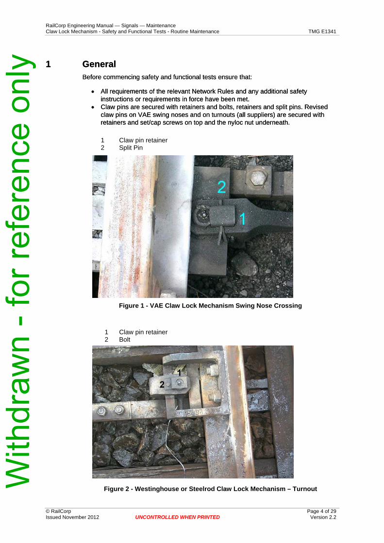
• Claw pins are secured with retainers and bolts, retainers and split pins. Revised claw pins on VAE swing noses and on turnouts (all suppliers) are secured with retainers and set/cap screws on top and the nyloc nut underneath.
• Claw pins are secured with retainers and bolts, retainers and split pins. Revised claw pins on VAE swing noses and on turnouts (all suppliers) are secured with retainers and set/cap screws on top and the nyloc nut underneath.
1 Claw pin retainer 2 Split Pin
Figure 1 - VAE Claw Lock Mechanism Swing Nose Crossing
Figure 4 – Revised Claw Pin for Westinghouse or Steel rod Claw Lock on Turnouts
Revised claw pins are being fitted to new turnouts and swing nose crossings and were retrofitted to existing turnouts and swing nose crossings from early 2004. The retainer for VAE swing nose crossings may change to the same as that shown for tangential turnouts from April 2004. With
Figure 5 – Westinghouse Claw Lock – Full height switch on turnouts
Figure 6 - Single Slip - claw pinned directly through switch flange. Claw pin, retainer and bolt are as for tangential turnouts – This pin can be replaced with the
revised claw pin shown in figure 4
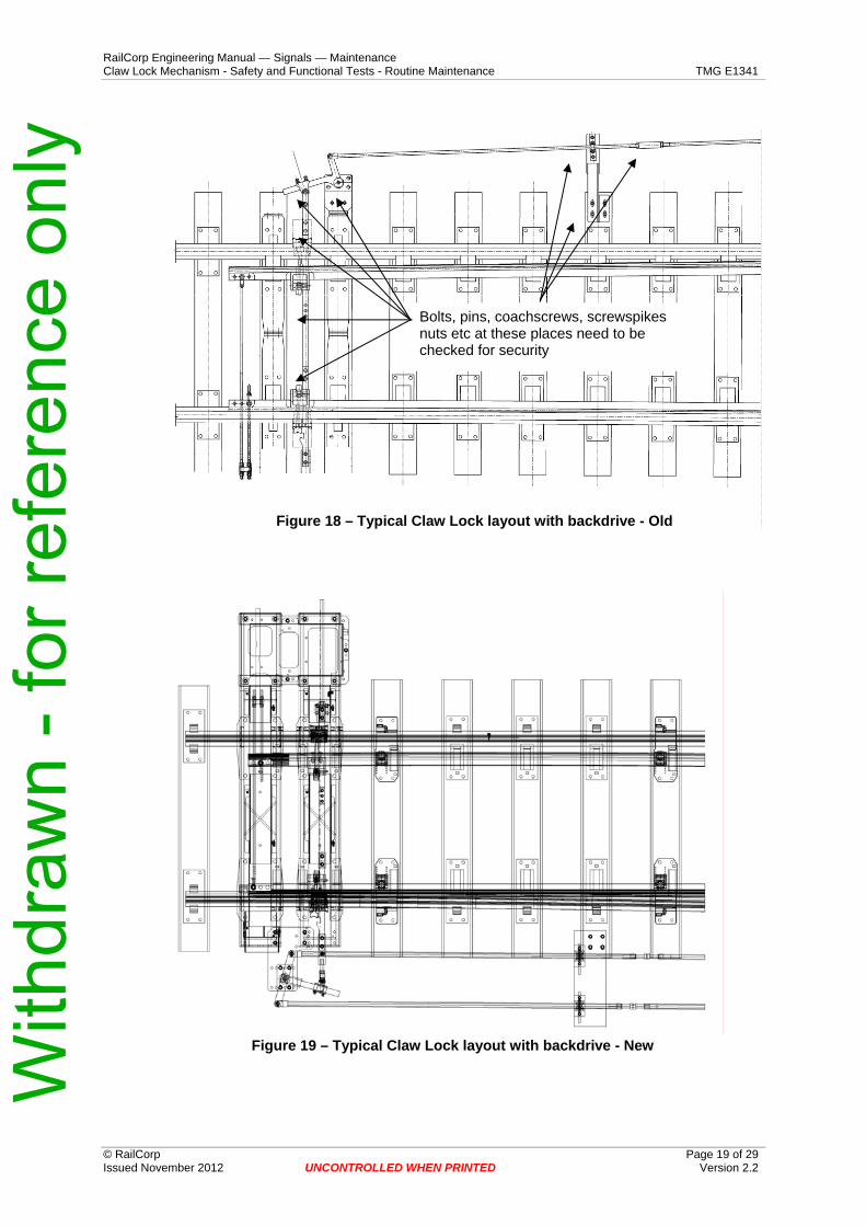
• The bolts securing the claw lock to the stock rail or swing nose crossing frame / wing rail / bracket are tight.
• The bolts securing the claw bracket to the switch or swing nose are tight. • The bolts securing the claw bracket to the switch or swing nose are tight. • Coupling bar bolts on three piece coupling bars on turnouts are tight. • Coupling bar bolts on three piece coupling bars on turnouts are tight. • Detection rod(s) are correctly secured at the switch or swing nose and at the
detector slides. Pins (where used) are fitted with split pins • Detection rod(s) are correctly secured at the switch or swing nose and at the
detector slides. Pins (where used) are fitted with split pins • The connection(s) between the coupling bar and the operating mechanism is
secure • The connection(s) between the coupling bar and the operating mechanism is
secure • Operating mechanisms and/or detectors are securely fastened to timbers or
concrete beams • Operating mechanisms and/or detectors are securely fastened to timbers or
concrete beams
It is not always necessary to use a spanner to check that a bolt and/or bracket is secure. This can be done visually by examining the joint between the bolt head and bracket or rod and between the bracket and whatever it is fastened to.
It is not always necessary to use a spanner to check that a bolt and/or bracket is secure. This can be done visually by examining the joint between the bolt head and bracket or rod and between the bracket and whatever it is fastened to.
If there is an unbroken grime build up over the joint then nothing is moving and the bolt is tight. If there is an unbroken grime build up over the joint then nothing is moving and the bolt is tight.
If a crack is visible in the grime build up over the joint or if there are fresh rust stains then there is movement and bolts need tightening. If a crack is visible in the grime build up over the joint or if there are fresh rust stains then there is movement and bolts need tightening.
Breaks in dust and grime films or fresh rust stains indicate bolts are not fully tightened
Figure 7 – Visual detection of movement
• Examine the condition of the tip of the switch on 53 kg and 60 kg turnouts. If the tip is fractured or blunted by impact, arrange for correction at the earliest opportunity.
• On tangential turnouts examine the condition of the head of the switch between 400 mm and 1000 mm from the tip. Particularly on turnouts which experience predominantly trailing traffic, the head can wear away on the curved switch. This means that a new “effective tip” forms around a metre from the tip of the switch. While unimportant for trailing moves it can be potentially dangerous for facing moves since it tends to form as a blunt exposed tip.
• Check for any lip or head overflow on the switch/swing nose or stock rail/wing rail. Overflow greater than 1.5 mm is likely to affect lock and detection settings and removal must be arranged.
• Examine the tip of swing nose crossings. There should not be any evidence of impact significant enough to cause blunting of the tip
2.1 Claw lock fitted with Westinghouse 84M Series Point Machines The following procedure is to be used to test the claw lock both when being commissioned and during periodic testing visits thereafter.
84M and D84M non-trailable machines may be tested under power or by using the crank handle or hand throw lever.
While T84M and TD 84M trailable machines may be tested under power operation, this is not recommended due to the limited capacity of the trail clutches to accept prolonged slippage without compromising service life.
a) Obtain the ESML key and crank handle or EOL key.
b) Place the crank handle in the machine if 84M or T84M, or the EOL key in the machine if D84M or TD84M to release the selector lever and hand throw lever.
c) Place the selector lever into the ‘hand’ position on the (T)D84M machine.
d) Using the hand throw lever or hand crank to operate the points, throw the points a couple of times to feel the effort required on the crank or hand throw lever.
e) Place a 4.8 mm gauge between switch and stock rail immediately above the claw. The gauge should extend for the full depth of the head of the switch.
Note: If an asymmetric (half height) switch is contacting the stock rail near the tip but is slightly off the stock rail (1 mm to 2 mm) at the claw, it will be necessary to position the gauge about mid way between the claw and the tip. If the gauge is used above the claw an overly tight lock setting is likely to result from attempting to ensure lock failure at 4.8_mm.
f) Close the switch against the gauge using approximately the same force on the crank or hand throw lever that was required to operate the points. Do not use excessive force in an attempt to make the hand throw lever complete its travel.
g) The claw must not swing completely out behind the claw lock and the coupling bar must not be able to complete its travel.
h) If necessary adjust the claw lock clearance. This can only be done by adding or subtracting shims between the claw bracket and the switch or, on tangential turnouts, by rotating the eccentric bush between the claw pin and claw bracket.
Note: Adjusting the throw of the points machine or adjusting the coupling bar will have no effect on the claw lock clearance. Provided these have been set up properly at installation there should never be any need for the machine throw or the coupling bar position to be touched. Variation in switch opening is relevant only to open switch detection settings. It cannot affect lock settings
Shim here
Eccentric Bush
Note;If the thickness of shims between the switch andclaw bracket exceeds 8mm, three of the 2mm shimsshould be relaced with a single 6mm shim.
Figure 9 – Position of shims and eccentric bush
Note that the eccentric bush is only found on tangential turnouts.
i) Place a 3.2 mm gauge between switch and stock rail and close the switch against the gauge. The claw should swing out behind the claw lock and the coupling bar should complete its travel. Do not use excessive force on the hand throw lever. If the claw does not swing out behind the claw lock, remove one shim (thin shim if present) and retest with both 4.8 mm and 3.2 mm gauges,
j) Only if the coupling bar does not complete its travel with a 3.2 mm gauge and there are no shims between the claw bracket and switch or if the removal of a shim means the claw will lock with the 4.8 mm gauge, test again with a 1.6mm gauge. With the 1.6 mm gauge in place the coupling bar must complete its travel.
If additional shims do not prevent the claw swinging out behind the lock box and the drive bar completing its travel with the 4.8 mm gauge in place, there is excessive switch roll.
Where anti-roll brackets are fitted, shim the anti-roll bracket to reduce the clearance under the stock rail. Clearance may be reduced to zero if necessary, but the bracket must not rub hard on the stock rail.
Where anti-roll stretchers are fitted check that the stretcher is securely fastened to the switches and that there is not excessive wear in the nylon sliding blocks within the stretcher.
Details of the anti-roll brackets and anti-roll stretchers are shown in TMG E1343 “Installation on turnouts”.
k) Repeat these tests for the opposite switch.
CAUTION With dual control (D84M and TD84M) it is possible for the dog clutch to fail
to engage correctly when the selector lever is returned to the “motor” position. After using the selector lever (whether the hand throw lever is
used or not), the machine should be tested under power to ensure that the dog clutch has engaged correctly.
If power operation is not possible, attempt to rotate the hand throw clutch (the unit which engages with the bevel gear in the “hand” position until it is felt to engage.
2.2 Claw lock fitted pneumatic motor. The following procedure is to be used to test the claw lock both when being commissioned and during periodic testing visits thereafter.
Pneumatic motor equipped points should be tested under power.
The procedure for testing is then the similar to that for 84M series electric machines
a) Place a 4.8 mm gauge between switch and stock rail immediately above the claw. The gauge should extend for the full depth of the head of the switch.
Note: If an asymmetric (half height) switch is contacting the stock rail near the tip but is slightly off the stock rail (1 mm to 2 mm) at the claw, it will be necessary to position the gauge about mid way between the claw and the tip. If the gauge is used above the claw an overly tight lock setting is likely to result from attempting to ensure lock failure at 4.8_mm.
b) Close the switch against the gauge.
The claw must not swing completely out behind the claw lock and the coupling bar must not be able to complete its travel.
If necessary adjust the claw lock clearance, by adding or subtracting shims between the claw bracket and the switch or, on tangential turnouts, by rotating the eccentric bush between the claw pin and claw bracket.
c) Place a 3.2 mm gauge between switch and stock rail and close the switch against the gauge. The claw should swing out behind the claw lock and the coupling bar should complete its travel. If the claw does not swing out behind W
the claw lock, remove one shim (thin shim if present) and retest with both 4.8_mm and 3.2 mm gauges,
d) Only if the coupling bar does not complete its travel with a 3.2 mm gauge and there are no shims between the claw bracket and switch, test again with a 1.6_mm gauge. With the 1.6 mm gauge in place the coupling bar must complete its travel.
Note: Adjusting the throw of the points machine or adjusting the coupling bar will have no effect on the claw lock clearance. Provided these have been set up properly at installation there should never be any need for the machine throw or the coupling bar position to be touched. Variation in switch opening is relevant only to open switch detection settings. It cannot affect lock settings
For 60 kg and 53 kg conventional layouts only;
If the claw still swings out behind the lock box and the drive bar completes its travel with the 4.8 mm gauge in place and this cannot be corrected by adding shims, then there is excessive switch roll.
e) Where anti-roll brackets are fitted, shim the anti-roll bracket to reduce the clearance under the stock rail. Clearance may be reduced to zero if necessary, but the bracket must not rub hard on the stock rail.
f) Where anti-roll stretchers are fitted check that the stretcher is securely fastened to the switches and that there is not excessive wear in the nylon sliding blocks within the stretcher.
Details of the anti-roll brackets and anti-roll stretchers are described in chapter 4 “Installation on turnouts” (TMG E1343).
g) Repeat these tests for the opposite switch.
3 Safety and Functional Tests - Switch Rollers Refer to document TMG E1291 Switch Rollers for information.
4 Safety and Functional Tests – Swing Nose Crossings
4.1 Claw lock fitted with Westinghouse 84M series point machine or with pneumatic motor. The following procedure is to be used to test the claw lock both when being commissioned and during periodic testing visits thereafter.
84M and D84M machines may be tested under power or by taking the ESML or EOL key and testing with the hand crank or hand throw lever.
Pneumatic motor equipped swing nose crossings should be tested under power.
• Place a 4.8 mm gauge between swing nose and one wing rail immediately above the claw. The gauge should extend for the full depth of the head of the switch.
Note: If the swing nose is contacting the wing rail near the tip but is slightly off the wing rail (1 mm to 2 mm) at the claw, it will be necessary to position the gauge about mid way between the claw and the tip. If the gauge is used above the claw an overly tight lock setting is likely to result from attempting to ensure lock failure at 4.8 mm. With
• Close the swing nose against the gauge under power or, for 84M machines, using approximately the same force on the crank or hand throw lever that was required to operate the swing nose. Do not use excessive force in an attempt to make the hand throw lever complete its travel.
• Close the swing nose against the gauge under power or, for 84M machines, using approximately the same force on the crank or hand throw lever that was required to operate the swing nose. Do not use excessive force in an attempt to make the hand throw lever complete its travel.
• The claw must not swing completely out behind the claw lock and the coupling bar must not be able to complete its travel.
• The claw must not swing completely out behind the claw lock and the coupling bar must not be able to complete its travel.
• If necessary adjust the claw lock clearance by adding or subtracting shims between the claw lock and wing rail or claw lock and mounting bracket. On VAE swing nose crossings only, coarse adjustment is also available by rotating the eccentric bush between the claw pin and claw bracket. The bush should only be used if total thickness of shims exceeds 8 mm.
• If necessary adjust the claw lock clearance by adding or subtracting shims between the claw lock and wing rail or claw lock and mounting bracket. On VAE swing nose crossings only, coarse adjustment is also available by rotating the eccentric bush between the claw pin and claw bracket. The bush should only be used if total thickness of shims exceeds 8 mm.
Shim here
Figure 12 - VAE Swing Nose – location of shims
Note that the shims must be placed between the adaptor and the claw bracket NOT between the adaptor and the rail.
• Place a 3.2 mm gauge between swing nose and wing rail and close the swing nose against the gauge. The claw should swing out behind the claw lock and the coupling bar should complete its travel. Do not use excessive force on the hand throw lever.
• If the coupling bar does not complete its travel with a 3.2 mm gauge, test again with a 1.6 mm gauge. With the 1.6 mm gauge in place the coupling bar must complete its travel. If it does not, remove shims.
Note: Adjusting the throw of the switch machine will have no effect on the claw lock clearance. Provided these have been set up properly at installation there should never be any need for the machine throw or the coupling bar position to be touched.
• Repeat these tests between the swing nose and the opposite wing rail.
5 Safety and Functional Tests – Detection – Turnouts and Swing Nose Crossings This procedure applies to Westinghouse 84M series switch machines and Westinghouse HLM, HM2 and HMX detectors. Detection contact assemblies are interchangeable.
A meter is required to determine whether contacts are open or closed.
5.1 Normally Closed Switch a) Close and lock the normal switch or close and lock the swing nose normal.
b) Ensure that there are no flat spots on the detector contact rollers.
c) Check the position of the contact roller in relation to the end of the notch in the detector slide connected to the normal switch or in the swing nose normal detector slide.
c) Check the position of the contact roller in relation to the end of the notch in the detector slide connected to the normal switch or in the swing nose normal detector slide.
d) On new installations or whenever replacement of the HM or HLM detector or detector slides are necessary, the designated contact block is to be proved to "open", using a voltmeter, when the detector roller has reached a position along the slide notch that would activate the contact block.
d) On new installations or whenever replacement of the HM or HLM detector or detector slides are necessary, the designated contact block is to be proved to "open", using a voltmeter, when the detector roller has reached a position along the slide notch that would activate the contact block.
e) Check the gap between the roller and the end of the notch with the 2.0 mm gauge. (refer Appendix B). This gauge must not fit.
e) Check the gap between the roller and the end of the notch with the 2.0 mm gauge. (refer Appendix B). This gauge must not fit.
f) Check again with the 1.0 mm gauge. This should fit easily. If the gap between roller and end of notch is incorrect adjust the slide position. Note that each full turn of a nut on the detector rod is equal to 2.5 mm of slide movement. ie 1/6 of a turn or 1 flat ≈ 0.5 mm
f) Check again with the 1.0 mm gauge. This should fit easily. If the gap between roller and end of notch is incorrect adjust the slide position. Note that each full turn of a nut on the detector rod is equal to 2.5 mm of slide movement. ie 1/6 of a turn or 1 flat ≈ 0.5 mm
g) Repeat for the reverse switch or swing nose reverse. g) Repeat for the reverse switch or swing nose reverse.
Note: A gap of 1.5 mm between the contact roller and the end of the notch in the detector slide will result in detection contacts open circuiting when the switch or swing nose has opened 4.0 mm to 4.5 mm.
Note: A gap of 1.5 mm between the contact roller and the end of the notch in the detector slide will result in detection contacts open circuiting when the switch or swing nose has opened 4.0 mm to 4.5 mm.
5.2 Open Switch Open switch detection is non-adjustable. The amount of latitude available for open switch detection will depend on the switch opening. The detector is capable of accepting switch openings between approximately 100 mm and 145 mm. (Note that ranges of 95 mm to 140 mm and 105 mm to 150 mm may be encountered.)
Switch Opening mm Open switch detection available mm Latitude mm
110 105 to 95 5 to 15 120 105 to 95 15 to 25 130 105 to 95 25 to 35 140 105 to 95 35 to 45 150 105 45
Latitude is the movement of the coupling bar before open switch detection will break
CAUTION Where pneumatic motors without motor detection contacts are used, the switch opening must not exceed 130 mm (for 53 kg rail = 115 mm) under
any circumstances. Check the switch opening where these motors are fitted.
Note also that at commissioning or after detector renewal, the open switch detection must be tested to ensure that detection open circuits at least 25 mm (for 53 kg rail = 20 mm) before the coupling bar releases the locked claw.
5.3 Coupling Bar Detection – Pneumatic Motors When pneumatic motors are fitted with microswitches, detection is as for “Pneumatic Motor Detection” described in clause 6
When a separate detector is fitted to the coupling bar, the detection contacts should make 4 mm to 5 mm before the coupling bar reaches full travel for both the normal and reverse sides.
5.4 Pneumatic Motor Detection (where fitted) A meter is required to determine whether contacts are open or closed
a) Ensure that the motor is in the fully normal position
b) Using the appropriate gauge check that the clearance between the actuator head and the microswitch plungers at the reverse end of the motor is not less than 1 mm.
c) Examine the switches at the normal end of the motor. The ring in the microswitch plunger should be in line with the microswitch body.
d) Operate the motor to the fully reverse position.
e) Using the appropriate gauge check that the clearance between the actuator head and the microswitch plungers at the normal end of the motor is not less than 1 mm.
f) Examine the switches at the reverse end of the motor. The ring in the microswitch plunger should be in line with the microswitch body. W
g) Loosen the locknuts and adjust if necessary. Apply Loctite 242 and re-tighten the locknuts or re-tighten the locknuts and apply Loctite 290 “wick-in”.
g) Loosen the locknuts and adjust if necessary. Apply Loctite 242 and re-tighten the locknuts or re-tighten the locknuts and apply Loctite 290 “wick-in”.
1mm thick gauge
Figure 15 - Pneumatic Motor Detection
5.5 U5A on EP Independent switches Normal Position
Ensure all connections are tight and switch is sitting up against stock rail
a) Place a 3.2 mm gauge between switch and stock rail. The gauge should extend for the full depth of the head of the switch.
b) With the gauge inserted check that the corresponding detector contacts are just made with only light tension required to open circuit contacts.
c) If contacts require adjustment loosen the appropriate clamping screw and turn the cam to the required position turning the driving screw to obtain the correct contact tension.
d) Retighten clamping screw
e) Move points fully over and back with 3.2 mm gauge between switch and stock rail and check if adjustment is correct
f) Place a 1.6 mm gauge between switch and stock rail. The gauge should extend for the full depth of the head of the switch.
g) With the gauge inserted check that the corresponding detector contacts are fully made.
h) If contacts require adjustment loosen the appropriate clamping screw and turn the cam to the required position using the driving screw. Retighten clamping screw
i) Move points fully over and back with 1.6 mm gauge between switch and stock rail and check if adjustment is correct
6.1 Zonal Inspection A zonal inspection is essentially a visual and audible inspection of claw lock operation. It consists of viewing and listening to the claw lock mechanism operation to ensure: -
• That the claw is locking correctly out behind the claw lock and that the coupling bar is travelling through and securing it in place.
• That all pins are secured by retaining plates, nuts and/or split pins. Retainers, where secured by bolts or set screws, must not show any sign of movement.
• That components are secure – there is no visual indication that the claw lock is moving or the machine is moving as the claw lock mechanism operates.
• That the coupling bar and the machine throw bar move in unison. • That the detector rods and machine slides commence to move with the switches
without any lag. • That the machine does not make any unusual sounds when operating
6.2 Trackwork Visual examination of the general condition of the turnout.
In particular check:
• Fit of switches to stock rail.
Acceptable fits are:
Turnout Type Maximum gap at tip
Recommended Maximum gap at centre of head machining
Recommended Maximum gap at end of head machining
Tangential 2 mm 8 mm 8 mm 60 kg 1 mm 6 mm 8 mm 47 kg and 53_kg 0 mm 4 mm 6 mm
Gap at the end of the machiningon the head of the switch.
Gap at the tip of the switch
Gap at the centre of the machining
Figure 16 – Fit of switch to stock rail
• Bearing of switches on plates. The switch must not be more than 1.5 mm clear of the A and B plates when closed.
• Variations in top surface and twist for the length of the switch and ahead of the switch which are affecting the free movement of the switch on the plates. N.B. No switch will bear evenly on all plates. If the movement of the switch is free and it is not unduly heavy to operate then the bearing, on whatever number of plates, is satisfactory. As a general rule the top surface and twist should be better than exceedent category 4 for at least 50 metres ahead of and through the turnout. (Exceedent category 4 is defined in Civil Engineering Standard C2009 “Base Operating Condition Standards of Track Geometry”)
• Lateral movement of the stock rail. This should not exceed 1.5 mm unless the turnout is mounted on resilient pads such as “Cologne Eggs”. With resilient mounting up to 3 mm lateral movement may be possible. (Special arrangements must be made for detector mounting in this case). Lateral movement indicates loose rail brace bolts and/or loose chair or plate bolts or screw spikes
• Longitudinal movement of the switch or stock rail pair relative to one another is not more than 15 mm for tangential turnouts and 10 mm for conventional turnouts.
• One switch and/or stock rail is not more than 25 mm ahead of the other switch and/or stock rail.
• On 53 kg and 60 kg turnouts, security of rail brace bolts, switch chocks, screw spikes and/or plate bolts.
Report or arrange for the correction of any deficiencies found.
6.3 The claw lock mechanism – Applies to all types of turnouts a) Remove any build up of dirt and grease between the claw bracket and sliding
bush and between the claw and coupling bar where it passes through the claw lock.
b) The Claw and or claw lock should not show wear grooves on the locking faces more than 1.5 mm deep. If wear exceeds this depth, the claw lock and/or claw should be replaced as soon as possible. Wear must not be allowed to exceed 3_mm.
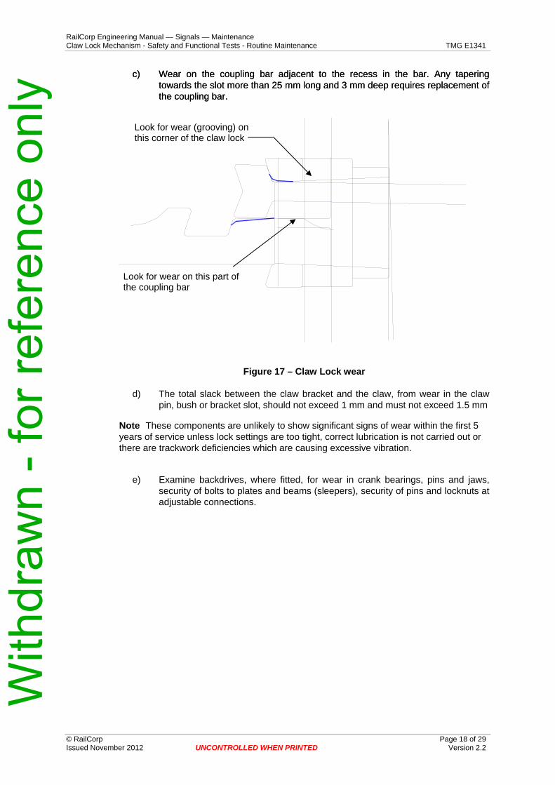
c) Wear on the coupling bar adjacent to the recess in the bar. Any tapering towards the slot more than 25 mm long and 3 mm deep requires replacement of the coupling bar.
c) Wear on the coupling bar adjacent to the recess in the bar. Any tapering towards the slot more than 25 mm long and 3 mm deep requires replacement of the coupling bar.
Look for wear (grooving) on this corner of the claw lock
Look for wear on this part of the coupling bar
Figure 17 – Claw Lock wear
d) The total slack between the claw bracket and the claw, from wear in the claw pin, bush or bracket slot, should not exceed 1 mm and must not exceed 1.5 mm
Note These components are unlikely to show significant signs of wear within the first 5 years of service unless lock settings are too tight, correct lubrication is not carried out or there are trackwork deficiencies which are causing excessive vibration.
e) Examine backdrives, where fitted, for wear in crank bearings, pins and jaws, security of bolts to plates and beams (sleepers), security of pins and locknuts at adjustable connections.
f) Ensure that claw lock covers hinge pins are secure and that covers cannot foul the claw or coupling bar. DO NOT remove covers, this will only result in faster contamination and wash off of lubricant.
g) The alignment of the coupling bar and the operating mechanism throw bar (or piston rod) should be such that when viewed from above they are either in a straight line or at least parallel to one another if offset. Misalignment indicates longitudinal movement of one or both stock rails. Small misalignments can be corrected by adjusting the position of one or both claw locks on the stock rail provided that this does not result in the claw pin bush being within 15 mm of one end of the slot in the claw bracket.
h) Lubricate
– the locking faces of the claw and claw lock – the sliding surfaces of the claw, coupling bar and claw lock – the sliding surfaces of the bush and claw bracket and the claw pin – Backdrive cranks and crank pins where required (i.e. where self-lubricating
and/or plastic bushes are not used).
There are a range of lubricants suitable for claw locks, all greases for heavy duty service and with molybdenum disulphide, are listed in Appendix A.
Note: The list is not exclusive and there are other lubricants which may be satisfactory in areas where the environment and operating conditions are not particularly harsh or where lubricating intervals are more frequent.
CAUTION Dry switch plate lubricants are generally not suitable for claw locks and
must not be used on claw locks on swing nose crossings.
Lubrication intervals will vary from location to location and will depend on usage (number of operations normal - reverse - normal), tonnage over the turnout and the local environment.
Generally lubrication of the claw lock, if the listed greases are used, should not be required at intervals of less than 4 weeks unless the environment is particularly harsh, and may, under benign environmental conditions and moderate usage, be extended up to 8 weeks.
7.1 Zonal Inspection (all swing nose crossings) A zonal inspection is essentially a visual and audible inspection of claw lock operation. It consists of viewing and listening to the claw lock mechanism operation to ensure: -
• That the claw is locking correctly out behind the claw lock and that the coupling bar is travelling through and securing it in place.
• That all pins are secured by retainers and split pins or nuts and/or by split pins. • That components are secure – there is no visual indication that the claw lock is
moving or the machine is moving as the claw lock mechanism operates. • That the coupling bar and the machine throw bar move in unison. • That the detector rod and machine slides commence to move with the swing nose
without any lag. • That the machine does not make any unusual sounds when operating
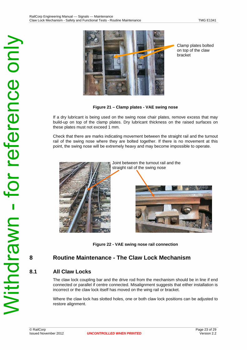
7.2 VAE Swing nose crossings. The clamp plates are part of the fastening system between the claw bracket and the swing nose and as such should be tight and not attempting to rotate. However there may be instances where the clamp plates do rotate. This can be tolerated provided that they are still firmly clamping the claw bracket to the foot of the swing nose.
If tightening does become necessary, the appropriate sized open ended spanner will need to be modified by narrowing the head until it fits between the raised edges of the clamp plates and bending the head at 45 degrees. This is then used to hold the head of the bolt while a socket is used on the nyloc nut under the claw bracket.
While the clamp plates should be clear of the underside of the wing rail, rubbing will sometimes occur. If this is only very light it is of no concern, however it can indicate a deterioration in the top surface of the track through the swing nose and means a hollow is developing under the wing rails and baseplate at the tip of swing nose. (Note: Swing nose crossings supplied post July 2003 will have clamp plates with more clearance from the underside of the wing rail)
To prevent a hole or dip forming under the swing nose it is essential that there is sufficient ballast left in the bays in which the claw lock and detector rod(s) are operating. Only sufficient ballast to clear the claws, claw pins, coupling bar and claw bracket should be removed. 30 mm to 40mm clearance from the ballast is sufficient.
Removal of ballast for most or all of the depth of the sleeper bays will lead to pumping which will cause excessive wear on the swing nose crossing and the equipment attached to it
If a dry lubricant is being used on the swing nose chair plates, remove excess that may build-up on top of the clamp plates. Dry lubricant thickness on the raised surfaces on these plates must not exceed 1 mm.
Check that there are marks indicating movement between the straight rail and the turnout rail of the swing nose where they are bolted together. If there is no movement at this point, the swing nose will be extremely heavy and may become impossible to operate.
Joint between the turnout rail and the straight rail of the swing nose
Figure 22 - VAE swing nose rail connection
8 Routine Maintenance - The Claw Lock Mechanism
8.1 All Claw Locks The claw lock coupling bar and the drive rod from the mechanism should be in line if end connected or parallel if centre connected. Misalignment suggests that either installation is incorrect or the claw lock itself has moved on the wing rail or bracket.
Where the claw lock has slotted holes, one or both claw lock positions can be adjusted to restore alignment.
Where there are no slotted holes, the cause of the misalignment needs to be determined and corrected if it is sufficient to cause binding between claw, coupling bar and claw lock. If it has not yet reached that stage, the moving components must be restrained to prevent further misalignment.
Where there are no slotted holes, the cause of the misalignment needs to be determined and corrected if it is sufficient to cause binding between claw, coupling bar and claw lock. If it has not yet reached that stage, the moving components must be restrained to prevent further misalignment.
Figure 23 – Claw Lock showing build up of dirt and grease
a) Remove any build up of dirt and grease between the claw and claw bracket and between the claw and coupling bar where it passes through the claw lock on each side of the swing nose.
b) Examine for:
i) Wear on the locking faces of the claw and the claw lock. If there is grooving more than 1.5 mm deep the claw and/or claw lock should be replaced.
ii) Wear on the coupling bar adjacent to the recess in the bar. Any tapering towards the slot more than 25 mm long and 3 mm deep requires replacement of the coupling bar.
Look for wear (grooving) on this corner of the claw lock
• Wear in the claw pin, the claw or the eccentric bush. • Wear between the eccentric bush and the claw bracket.
If there is more than a total of 1 mm slack between claw and claw bracket, parts should be renewed
Note These components should not show significant signs of wear within the first 5 years of service unless lock settings are too tight, correct lubrication is not carried out or there are trackwork deficiencies which are causing excessive vibration.
c) Lubricate the claw pin and the locking and sliding faces of the claw and coupling bar. One of the greases listed in Appendix A should be used. Dry switch plate lubricants are not suitable for these claw locks.
d) Ensure that covers are secure and that they cannot foul the claw or coupling bar.
e) Check that there is no more than about 1.5 mm of movement between the coupling bar and the drive rod from the switch machine. Movement indicates bush and/or pin wear and if over 1.5 mm bush and pin replacement should be programmed.
f) Examine the condition of the split pin securing the claw pin retainer. The split pin must not be grooved to more than 20% of its diameter. The split pin hole in the retainer must not be worn to the extent it will allow the retainer to overlap the pin head by less than 3 mm.
g) Where revised pins (shoulder bolts – figure 3) are used check that there are one or two threads projecting through the nyloc nut on the bottom of the pin and that the socket head cap screw is tight against the turned down sides of the retaining plate.
9 Run Through of Claw Lock – Turnouts and Swing Nose Crossings. A run through of a claw lock mechanism, except where a turnout is fitted with a trailable operating mechanism, will result in some degree of damage to at least some of the components of the claw lock mechanism even though this may not be immediately visible.
There will also always be some damage to the switches or swing nose but with light vehicles it may not be sufficient to necessitate replacement.
The extent of damage will be determined to a large extent by the weight and number of vehicles involved and the speed of the run through. While a light track maintenance vehicle may only appear to cause minimal distortion of the switch or swing nose, it will still have imposed excessive loads on some claw lock components.
Since the loads imposed by a run through are impossible to accurately calculate, the components listed below, at least, should be replaced if a run through occurs.
If a locomotive or train has run through the turnout or swing nose then components should be replaced before restoration to service. If the run through is by a light track vehicle and there is no obvious damage, replacement may be at the earliest opportunity.
Where component replacement is delayed, a weekly inspection of the claw lock installation should be implemented.
• The claw lock (box) of the closed switch. • The claw, claw pin and claw bracket of the closed switch. • The claw, claw pin and claw bracket of the open switch.
For a swing nose
• The claw lock (box) on the closed side of the swing nose • The claw and claw pin on the closed side of the swing nose. • Bolts securing claw locks and claw brackets.
Claws, claw locks and (some) claw brackets are steel castings that can develop hairline cracks if severely over stressed. These cracks will not necessarily be immediately evident.
CAUTION Any components which have been removed after a run through must either be destroyed or, if there are no visible signs of damage, be forwarded to an
accredited facility for crack testing.
10 Routine Maintenance – Operating Mechanisms
10.1 Latched Pneumatic Motor
10.1.1 Description The motor is a 125 mm bore, 180 mm stroke (some early motors were 200 mm stroke) air cylinder fitted with an internal latching device at each end and, in some cases, fitted with microswitches at each end to detect piston position.
The latching devices prevent the piston from drifting from the normal or reverse position if air pressure is lost. Air pressure applied to the cylinder releases the latches before moving the piston.
The microswitches, where fitted, are operated by a push rod driven by a ramp on the piston rod and are used to detect the motor fully normal or fully reverse.
The motors are usually fitted with adjustable flow control valves on the normal and reverse ports which enable the speed of operation of the points to be varied.
10.1.2 Routine Maintenance - Mechanical There is no periodic preventative maintenance schedule for the internal parts of the air motor. Motors are pre-lubricated at manufacture and in-service lubrication is not required.
Observe the operation of the points. If considered too slow or too fast, adjust the flow control valves on the motor ports.
Observe the operation of the latches and ensure that they are returning to the latched (fully down) position.
If there is any defect with the operation of the motor piston or latches or switch actuators, the motor must be changed and returned to the depot or workshop to be forwarded for overhaul. With
draw
n - f
or re
fere
nce
only
RailCorp EngineClaw Lock Mechanism - Safet
ering Manual — Signals — Maintenance y and Functional Tests - Routine Maintenance TMG E1341
10.1.3 Routine Maintenance - Electrical • Check that the switch driving cap and locknut on the microswitch actuator are tight. • Check the operation of the microswitches. This is done with the actuator in the
retracted position. Depress and release each switch by hand to ensure that the switch plunger returns freely to the extended position without any grating or hesitation. The microswitches are sealed assemblies and cannot be repaired.
CAUTION The signaller must be advised before this check is carried out, as the detection circuits will be broken when the microswitch plungers are
depressed. The check must not be carried out if there is any train within the extent of the approach locking for the points unless that train is stationary.
• Examine the wiring and terminal block for any damage or loose connections.
If it is necessary to change microswitches this is best carried out in the depot but can be carried out on site if necessary. Proceed as follows:-
• Disconnect wiring from the terminal block • Remove the screws securing the switch mounting plate to the terminal box • Remove the switch driving cap from the actuator (leave the locknut in place) • Remove the switches and mounting plate from the terminal box and switches from
the mounting plate. • Repeat these steps in reverse order to refit new switches.
10.1.4 Pneumatic Motor Overhaul At 3 to 5 year intervals, depending on number of operations and operating environment, pneumatic motors should be removed from the track for replacement of piston seals, gland seals, latch seals and microswitch actuator seals. Motors should be returned to their manufacturer for overhaul.
10.2 HM2 Detectors • Visual examination of contact assemblies is usually sufficient to detect
deterioration. Look for blackening on the inside of the plastic case or discolouration of contact springs.
• Detector rollers should rotate freely and there should be no evidence of flat spots. There should be little or no slack in the pivots and pins of the detection linkages.
With
draw
n - f
or re
fere
nce
only
Engineering Manual — Signals — Maintenance w Lock Mechanism - Safety and Functional Tests - Routine Maintenance TMG E1341
Appendix A Lubrication Alternatives for Claw Locks and 84M Series Switch Machines Manufacturer Product Comment Applications
Shell Retinax HDX2 Heavy duty EP grease, contains MoS2, suitable for heavy duty applications with shock loading in hostile environments
Claw Lock components
Caltex Molygrease Heavy Heavy duty EP grease, contains MoS2, high water and corrosion resistance, high load carrying capacity Claw Lock components
Rocol Tufgear 90 ** Heavy duty grease, contains MoS2, high corrosion resistance, high load capacity
Claw Lock componentsgears in 84M machines
Mobil Mobilgrease Special Heavy duty EP grease, contains MoS2, high corrosion resistance, high resistance to water washout Claw Lock components
Caltex Texclad 2 ** Heavy duty grease, contains MoS2 and graphite, is high adhesive, highly resistant to water wash out, resists flaking at low temperatures
Claw Lock componentsgears in 84M machines
Shell Malleus GL500 ** Premium EP grease, contains MoS2, inhibits corrosion, resists drying out and ‘squeeze out’, reduced dirt and dust retention.
Claw Lock componentsgears in 84M machines
Note: All of the above greases can be used on the gears within 84M series machines. However the greases marked ** are open gear greases which will resist “fling off”


![revista 041 [4]](https://static.documents.pub/doc/80x56/568bd5ae1a28ab20349959c7/revista-041-4.jpg)


