2305 Pleasant View Rd. Middleton Industrial Park Middleton, WI 53562 PH: (608) 831-2585 FAX: (608) 831-7407 TN-1 TECHNICAL NOTES Temperature Sensing and Transmitting Temperature Measurement The success of the HVAC industry is dependent upon the ability to accurately measure and control conditions such as temperature, pressure, or relative humidity. The most common measurement is temperature. ACI addresses temperature measurement by supplying quality platinum RTD’s and transmitters. History RTD is an acronym for Resistive Temperature Detector. In 1821, Sir Humphrey Davey discovered that the electrical resistance of a pure metal increased with an increase in temperature. It is now a well known fact that the resistivity of metals varies with temperature. However, not all metals are suitable for thermometry . A good candidate for an RTD would be a metal with a high resistivity and a temperature coefficient that is stable over time. In 1871, Sir William Siemens suggested that platinum was one such metal and began using it as a practical resistance thermometer. In 1968, the International Practical Temperature Scale was created, and today pure platinum RTD’s are the standard instruments for interpolation between the fixed points of the scale. Some of the fixed points on the scale are the triple point of water (0.01°C), the boiling point of water (100°C), the triple point of hydrogen (13.81 K), and the freezing point of zinc (419.505°C). Advantages and Disadvantages There are certain advantages of using an RTD over other types of temperature sensors (e.g. thermocouples, thermistors, and IC sensors): 1) The change in resistance versus the change in temperature is more linear 2) RTD’s have the highest accuracy 3) RTD’s have excellent stability over time There are also some minor disadvantages of using a platinum RTD over other types of temperature sensors. At a given size, the nominal resistance is low and the change in resistance is much smaller as compared to other different types of sensors. RTD’s are also more expensive than many other different types of sensors. Types of RTD’s Although platinum may be the most recognizable type of RTD, it is not the only metal used to make RTD’s. Other metals such as Nickel, Nickel Alloys, Gold, Silver, Tungsten, Copper, and Rhodium are also used. A comparison of platinum with copper, nickel, and nickel alloys is discussed here.
Transcript
2305 Pleasant View Rd. Middleton Industrial Park Middleton, WI 53562 PH: (608) 831-2585 FAX: (608) 831-7407
TN-1
TECHNICAL NOTES Temperature Sensing and Transmitting Temperature Measurement
The success of the HVAC industry is dependent upon the ability to accurately measure and control conditions such as temperature, pressure, or relative humidity. The most common measurement is temperature. ACI addresses temperature measurement by supplying quality platinum RTD’s and transmitters.
History
RTD is an acronym for Resistive Temperature Detector. In 1821, Sir Humphrey Davey discovered that the electrical resistance of a pure metal increased with an increase in temperature. It is now a well known fact that the resistivity of metals varies with temperature. However, not all metals are suitable for thermometry . A good candidate for an RTD would be a metal with a high resistivity and a temperature coefficient that is stable over time. In 1871, Sir William Siemens suggested that platinum was one such metal and began using it as a practical resistance thermometer. In 1968, the International Practical Temperature Scale was created, and today pure platinum RTD’s are the standard instruments for interpolation between the fixed points of the scale. Some of the fixed points on the scale are the triple point of water (0.01°C), the boiling point of water (100°C), the triple point of hydrogen (13.81 K), and the freezing point of zinc (419.505°C).
Advantages and Disadvantages
There are certain advantages of using an RTD over other types of temperature sensors (e.g. thermocouples, thermistors, and IC sensors):
1) The change in resistance versus the change in temperature is more linear 2) RTD’s have the highest accuracy 3) RTD’s have excellent stability over time
There are also some minor disadvantages of using a platinum RTD over other types of temperature sensors. At a given size, the nominal resistance is low and the change in resistance is much smaller as compared to other different types of sensors. RTD’s are also more expensive than many other different types of sensors.
Types of RTD’s
Although platinum may be the most recognizable type of RTD, it is not the only metal used to make RTD’s. Other metals such as Nickel, Nickel Alloys, Gold, Silver, Tungsten, Copper, and Rhodium are also used. A comparison of platinum with copper, nickel, and nickel alloys is discussed here.
2305 Pleasant View Rd. Middleton Industrial Park Middleton, WI 53562PH: (608) 831-2585 FAX: (608) 831-7407
TN-2
As previously mentioned a high resistivity is an important benefit in an RTD. Platinum has a resistivity of 10.6 mW-cm at 20°C. A high resistivity ensures a high nominal resistance in a small sensing element. The nominal resistance is the resistance measured at 0oC. The relation between resistivity and resistance is characterized in equation #1.
Equation #1: R= p L A where: R = the resistance in ohms
r = the resistivity of the material (W -cm) L = the length of the material in cm A = the cross sectional area in cm2 (width times thickness)
Using equation #1 above, it can be found that a sensing element produced using a metal with a small resistivity will be larger than a sensing element using platinum. A benefit of the smaller size of a platinum RTD is that the sensor will have a faster response time (the time required to reach the final temperature). In general, the larger the RTD, the longer it will take the sensor to reach its final temperature after a sudden temperature change. Platinum is also a Noble metal, meaning it has a stable valence electron band and will be chemically inactive. A chemically inactive substance will be more stable over time (i.e. the resistance at a set temperature will not drift). Another benefit of using platinum is the nearly linear temperature-resistance curve over a large temperature range of -260 to 1100oC. Finally, platinum is easy to refine and machine. Nickel and nickel alloys have a relatively high resistivity (6.84 mW-cm at 20oC) thus the nominal resistance is high for a given size RTD. Nickel costs much less than platinum. However, nickel does suffer from being nonlinear over a large temperature range, tends to drift over time, and only has an accuracy of about 1oC at l00oC. If accuracy is not as vital and the RTD is used over a small range (0 to 100oC) the temperature-resistance curve can be approximated as linear. Copper has a lower resistivity than platinum. Therefore, it requires a larger element for an equivalent nominal resistance. An advantage to copper is that it is very linear for temperatures under 120oC. The rest of the metals used as RTDs tend to have smaller resistivities and are more expensive than platinum. The different properties of each metal make it desirable for specific applications. For HVAC applications, the platinum RTD is the best choice for both cost and performance.
Construction of RTD’s The objective in producing a high quality RTD, is to create a useful nominal resistance. The standard nominal resistances that are available are 100 and 1000 ohms. The two main types of RTD’s that are available include both Wirewound or Platinum RTD’s. A wirewound RTD is produced by winding the metal on a ceramic or glass bobbin and then sealing it in glass or ceramic. The effective area of the coil must be kept as small as possible to reduce induction effects, and the winding must be free to expand and contract without breaking. A wirewound RTD is generally a little bit larger than its thin film counterpart and costs approximately twice as much.
2305 Pleasant View Rd. Middleton Industrial Park Middleton, WI 53562 PH: (608) 831-2585 FAX: (608) 831-7407
TN-3
ACI supplies both platinum thin film and wirewound RTD’s. Thin film platinum RTD’s are produced by depositing a metal film on a ceramic substrate. The film is trimmed with a laser to obtain the desired nominal resistance and then sealed. The thin film RTD’s are much smaller in size and subsequently have a much faster response time. A thin film RTD is also less expensive due to the fact that they are much easier and faster to produce.
RTD Specifications
ACI utilizes a quality Class A platinum RTD that can be used alone or in conjunction with any of our temperature transmitters. The RTD is linear in its operating range from -200oC to 850oC. An RTD is characterized by its resistance vs. temperature (R-T) curve which is ideally linear. Equation #2 is the relation between resistance and temperature for RTD’s supplied by ACI.
Equation #2 R = RN + RN x TCR x t where: R = Resistance of the sensing element at a specific temperature RN = Nominal resistance
TCR = Temperature coefficient of resistivity t = Actual temperature in degrees Celsius
The definition of TCR is the temperature coefficient of resistivity. The TCR of this RTD is 0.00385 Ohms/Ohms/oC and is the slope of its R-T curve. The RTD meets IEC Pub 751-1983, and DIN EN 60751 Class A standards. At 0oC (32oF) the RTD is within +/- 0.06 Ohms. of its nominal resistance. At other temperatures in the operating range the tolerance is +/- (0.3 + 0.005T) where T is the actual temperature.
Temperature Resistance Value 100 Ohm pRTD (oC) (Ohms) oC oF Ohms -100 60.25 +/- 0.8 +/- 1.44 +/- 0.32
Table I: The table shows the bounds the RTD is guaranteed to fall within at certain temperatures. The bounds are shown in oC, oF, and Ohms.
The stability of the RTD is tested by continuously heating the sensor at 400oC for 6,000 hours. After heating, the nominal resistance is within 0.055 Ohms (0.14oC). The response time is then measured by introducing a sudden temperature change and measuring the time it takes for the RTD to reach 90% of the final value. In air, moving at a velocity of 1 m/s the response time is 25 seconds, with air velocity of 3 m/s the response time is 17 seconds, and in still water the response time is 22 seconds.
2305 Pleasant View Rd. Middleton Industrial Park Middleton, WI 53562 PH: (608) 831-2585 FAX: (608) 831-7407
TN-4
The accuracy of an RTD can be compromised by the amount of self-heating. The current passing through the element causes the self-heating (joule heating) that occurs in any resistor. The current flowing through the RTD should never exceed 2 mA. The magnitude of the self-heating is calculated using equation #3:
T = P / EK Equation #3
P= I2R / 1000 Equation #3A where: T = Self-heating in °C EK = Self-heating coefficient in mW/ oC P = Input power I = Input current R = Resistance of the element or RTD The value of EK varies with the medium, EK is 5 in air with a velocity of 1 m/s and 3 in still air. Transmitter
An RTD alone does not produce an output useful to most HVAC controllers. Many controllers will accept a current input from the transmitter. ACI produces the ACI/TT100 and ACI/TT1000 temperature transmitters to meet this objective. The design objective is to produce a current output linear with temperature using an RTD as the temperature sensor. There must also be immunity to long wire runs, load resistance, and electrical noise. The discussion below introduces ACI's temperature transmitters and explains how the design objectives are met.
Operating Principles ACI transmitters use an RTD as the temperature sensor. The RTD is connected in the circuit as the feedback resistor in a follower amplifier. The input voltage to the follower comes from a precision voltage reference. As the temperature changes, the output voltage of the follower changes. A potentiometer is included in the follower circuit that allows calibration of the gain to achieve 4 mA at the lower end of the span. Another follower with the same precision voltage reference input and a constant gain is also included. The heart of the circuit is a differential voltage to current converter. Each follower output is fed into opposing arms of the differential amplifier. The amplification of this stage can be adjusted until the required span is obtained. A higher gain is required to obtain small spans. The differential voltage to current converter is used for two reasons. The first reason is that any resistance connected from the output to the ground will not affect the current output because the output resistance of a current source is infinite. The second reason is that a differential voltage amplifier will always have a high CMRR (Common Mode Rejection Ratio ). A common mode input is any equal voltage at both arms of the input whether it be AC or DC. Having a high CMRR means any electrical noise picked up at the point of board placement will be filtered out.
2305 Pleasant View Rd. Middleton Industrial Park Middleton, WI 53562 PH: (608) 831-2585 FAX: (608) 831-7407
TN-5
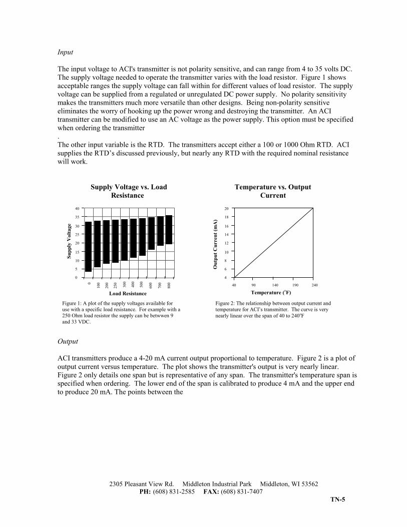
Input The input voltage to ACI's transmitter is not polarity sensitive, and can range from 4 to 35 volts DC. The supply voltage needed to operate the transmitter varies with the load resistor. Figure 1 shows acceptable ranges the supply voltage can fall within for different values of load resistor. The supply voltage can be supplied from a regulated or unregulated DC power supply. No polarity sensitivity makes the transmitters much more versatile than other designs. Being non-polarity sensitive eliminates the worry of hooking up the power wrong and destroying the transmitter. An ACI transmitter can be modified to use an AC voltage as the power supply. This option must be specified when ordering the transmitter . The other input variable is the RTD. The transmitters accept either a 100 or 1000 Ohm RTD. ACI supplies the RTD’s discussed previously, but nearly any RTD with the required nominal resistance will work.
Supply Voltage vs. Load Temperature vs. Output Resistance Current
Output ACI transmitters produce a 4-20 mA current output proportional to temperature. Figure 2 is a plot of output current versus temperature. The plot shows the transmitter's output is very nearly linear. Figure 2 only details one span but is representative of any span. The transmitter's temperature span is specified when ordering. The lower end of the span is calibrated to produce 4 mA and the upper end to produce 20 mA. The points between the
20
18 16
14
12 10
8
6
4
0
10
0
200
250
300
400
500
60
0 70
0 80
0
Load Resistance
Supp
ly V
olta
ge
40 90 140 190 240
Temperature ( F)
Out
put C
urre
nt (m
A)
Figure 1: A plot of the supply voltages available for use with a specific load resistance. For example with a 250 Ohm load resistor the supply can be betwwen 9 and 33 VDC.
Figure 2: The relationship between output current and temperature for ACI’s transmitter. The curve is very nearly linear over the span of 40 to 240oF
40
35 30
25
20 15
10
5
0
o
2305 Pleasant View Rd. Middleton Industrial Park Middleton, WI 53562 PH: (608) 831-2585 FAX: (608) 831-7407
TN-6
output are linear with temperature. ACI transmitters have an excellent accuracy of +/- 0.1% of the temperature span. If the span is 40 to 240oC, then at any point within the span the temperature is within 0.2oC of the actual temperature. The other factor contributing to accuracy is the self-heating of the RTD. At any point there is never more than 0.6 mA of current flowing through the RTD. Using equation 2, 0.6 mA current, and the different values for EK, typical temperature variances are outlined in table 2.
Typical Temperature Variances
Air Speed 100 Ohm RTD 1000 Ohm RTD v = 1 m/s 0.0072oC 0.072oC Still Air 0.012oC 0.12 oC
Table 2: The self-heating in degrees Celsius is calculated for a 0.6 mA current. The value of EK differs with the environment, the values are given earlier in the document. The table shows that self-heating creates insignificant error in the transmitter output. The transmitter board and RTD must be operated within their respective operating ranges. The board itself may be operated from temperatures as low as 32oF up to 158oF (0 to 70oC). The RTD is reliable and linear from -58 to 392oF (-50 to 200oC). The transmitter board and RTDs operating ranges differ, but the board may be separated from the RTD. One potential problem is that the resistance of the lead wires may affect the accuracy of the RTD if long runs of lead wire are added between the RTD and the transmitter. This can be avoided by keeping the board as close to the RTD as possible and allowing the separation to exist between the transmitter and controller. With 24 AWG copper wire, runs less than 30 feet will cause substantially less error than the inherent error of the RTD. The transmitter and controller can be separated by arbitrarily long wire runs with no adverse effects. The only limitation is that the resistance of the connection wire must be included with the load resistance. When using a large load resistance the output current will create a voltage drop nearing the input voltage. If the voltage drop over the load resistor is allowed to become too high, the difference between this voltage drop and the input voltage will become too small to power ICs and the circuit will cease to function.
2305 Pleasant View Rd. Middleton Industrial Park Middleton, WI 53562 PH: (608) 831-2585 FAX: (608) 831-7407
TN-7
Frequency Response of Selected Transmitters
Figure 3: The frequency response of transmitters. The test was performed by injecting a sine wave into the RTD input of ACI's and two other competitors transmitters. This test simulates
noise picked up inductively along the wire run to the RTD. The competitiors transmitters acted similarly, thus only one was plotted. The plot was created from an input signal magnitude of 40 mV but tests done at larger and smaller magnitudes produced equivalent results.
Figure 1 shows allowable output loads for different supply voltages. When the RTD and transmitter need to be separated, the risk of picking up electrical noise on the lead wires is prevalent. The noise rejection of ACI' s transmitter boards is a feature that separates it from the rest of the industry. Figure 3 shows the frequency response of the ACI transmitter compared with other companies transmitters. This type of plot is called a Bode plot. The frequency (x axis) is on a log axis and the y axis is the normalized gain expressed in decibels l. The plot was created by injecting a 40 mV p-p sine wave into the RTD input of each transmitter. As the frequency rises the ACI transmitter attenuates the noise while the rest let the noise signal pass unaffected. 1 A decibel (dB) is defined as 20 times the log10 of the output voltage divided by the input voltage. A dB value of 0 implies the output voltage is equal to the input voltage. Negative dB values mean the output voltage is less than the input voltage.
1 10 100 1000 10000 100000 1000000
Frequency (Hz)
10 0 -10 -20 -30 -40 -50 -60 -70 -80
Out
put (
dB)
All Noise passes with no attenuation
Noise is attenuated at all frequencies
As the Frequency of the noise rises the attenuation increases
ACI Output (dB) Competitors
2305 Pleasant View Rd. Middleton Industrial Park Middleton, WI 53562 PH: (608) 831-2585 FAX: (608) 831-7407
TN-8
Features ACI transmitters feature certain options that can be added to the room configuration. For certain systems an override switch is required. There are two methods of achieving override offered with the transmitter. The first is a normally open switch that will short out the sensing element and create a low current output (1.5 mA). The other option is a separate set of terminal blocks. When the switch is pressed the poles of the terminal block are shorted together. Another common feature used with some controllers is a setpoint function. ACI can accommodate nearly all setpoint resistor values. The setpoint can also be configured as either Direct or Reverse acting.


![ASD INTERFACE SERIES ICC - Toshiba€¦ · 1600 Aspen Commons, Suite 210 Middleton, WI USA 53562-4720 Tel: [608] 831-1255 Fax: [608] 831-2045 ... may it provide information on every](https://static.documents.pub/doc/80x56/5eb9ed2e8b614e0204517d00/asd-interface-series-icc-toshiba-1600-aspen-commons-suite-210-middleton-wi-usa.jpg)
