Technical Report A Continuous-Availability Solution for VMware vSphere and NetApp Using VMware High Availability and Fault Tolerance and NetApp MetroCluster NetApp and VMware, Inc. June 2010 | TR-3788 EXECUTIVE SUMMARY This document describes various failure scenarios in a virtual infrastructure environment and the solutions to recover from these failures by deploying VMware ® High Availability (HA), VMware Fault Tolerance (FT), VMware vCenter ™ Heartbeat, and NetApp ® MetroCluster. These solutions help maintain continuous availability of the computing and storage resources of the virtual infrastructure between sites, provide complete disaster recovery during loss of a site, and the ability to shift the complete operation of the environment between two sites to minimize disruption during scheduled downtime.
Transcript
Technical Report
A Continuous-Availability Solution for VMware vSphere and NetApp Using VMware High Availability and Fault Tolerance and NetApp MetroCluster
NetApp and VMware, Inc.
June 2010 | TR-3788
EXECUTIVE SUMMARY This document describes various failure scenarios in a virtual infrastructure environment and the solutions to recover from these failures by deploying VMware
® High Availability (HA), VMware Fault Tolerance
(FT), VMware vCenter™
Heartbeat, and NetApp® MetroCluster. These solutions help maintain
continuous availability of the computing and storage resources of the virtual infrastructure between sites, provide complete disaster recovery during loss of a site, and the ability to shift the complete operation of the environment between two sites to minimize disruption during scheduled downtime.
A Continuous Availability Solution for Virtual Infrastructure 2
VERSION INFORMATION ...................................................................................................... 36
A Continuous Availability Solution for Virtual Infrastructure 3
1. INTRODUCTION
This technical report provides an overview and describes the end-to-end implementation details of production-class continuous-availability solutions for virtual infrastructures consisting of VMware ESX™ Servers and NetApp storage systems.
1.1 INTENDED AUDIENCE
This document is for:
Customers and prospects looking to implement a continuous-availability solution for their virtual infrastructure consisting of VMware ESX Servers and NetApp FAS storage
End users and management seeking information on a continuous-availability solution in a production or dev/test environment
1.2 SCOPE
What this document describes:
End-to-end architecture overview of the continuous-availability solution for virtual infrastructure
Detailed design and implementation guide; configuration best practices
Reproducible test results that simulate common failure scenarios resulting from operational problems and real disasters
The scope of this document is limited to the following:
This report does not replace any official manuals and documents from NetApp and VMware on the products used in the solution or those from any other switch vendors referenced in the report.
This report does not discuss any performance impact and analysis from an end-user perspective during a disaster.
This report does not replace NetApp and VMware professional services documents or services.
This report does not discuss a regional (long-distance) disaster recovery solution. If you are looking for a regional disaster recovery solution in addition to the high-availability option discussed in this paper, contact your NetApp representative for further assistance.
1.3 ASSUMPTIONS AND PREREQUISITES
This document assumes familiarity with the following:
Basic knowledge of VMware‘s virtualization technologies and products: VMware vCenter Server 2.5 and vCenter Server 4.0, VMware Infrastructure 3
™, and VMware vSphere
™ 4.0
Basic knowledge of NetApp storage systems and Data ONTAP®
2 BACKGROUND
2.1 BUSINESS CHALLENGE
Economic challenges drive businesses to provide high levels of availability and business continuity while simultaneously achieving greater levels of cost savings and reduced complexity. As a result, data center infrastructure is increasingly virtualized because virtualization provides compelling economic, strategic, operational, and technical benefits. Planning a robust high-availability infrastructure solution for virtual data center environments hosting mission-critical applications is of utmost importance.
Some of the key aspects of an effective high-availability virtualized infrastructure should include:
Operational efficiency and management simplicity Cost effectiveness Architectural simplicity High performance Resiliency and flexibility VMware provides uniform, cost-effective failover protection against hardware and software failures within a virtualized IT environment with VMware high availability and fault tolerance.
A Continuous Availability Solution for Virtual Infrastructure 4
NetApp MetroCluster is a cost-effective, synchronous replication solution for combining high availability and disaster recovery in a campus or metropolitan area to protect against both site disasters and hardware outages. MetroCluster provides automatic recovery for any single storage component failure and single-command recovery in case of major site disasters, for zero data loss and recovery within minutes rather than hours.
Combining VMware HA and FT and NetApp MetroCluster technologies offers a great value proposition.
The combination provides a simple and robust continuous-availability solution for planned and
unplanned downtime in virtual data center environments hosting mission-critical applications.
Each of these solutions is discussed briefly in the next section.
2.2 CONTINUOUS-AVAILABILITY SOLUTIONS FOR VIRTUAL INFRASTRUCTURE
VMWARE SOLUTION: VMWARE HA (VI3 AND VSPHERE 4)
VMware cluster technology groups VMware ESX Server hosts into a pool of shared resources for virtual
machines and provides the VMware HA feature. When the HA feature is enabled on the cluster, each
ESX Server maintains communication with other hosts so that if any ESX host becomes unresponsive
or isolated, the HA cluster can negotiate the recovery of the virtual machines that were running on that
ESX host among surviving hosts in the cluster.
Figure 1) VMware HA architecture.
Note:
1. Setting up an HA cluster requires a vCenter Server. Once the cluster is set up, it can maintain HA
without further interaction with the vCenter Server.
2. VMware‘s distributed resource scheduler (DRS) is out of the scope of this document. However,
note that VMware DRS can be enabled simultaneously with VMware HA on the same cluster.
A Continuous Availability Solution for Virtual Infrastructure 5
VMWARE SOLUTION: VMWARE FT (VSPHERE 4 ONLY)
VMware Fault Tolerance leverages the well-known encapsulation properties of virtualization by building
high availability directly into the x86 hypervisor to deliver hardware-style fault tolerance to virtual
machines.
VMware FT provides continuous availability for mission-critical virtual machines by creating and
maintaining a secondary VM that is identical to (and able to replace) the primary VM in case of
hardware failure. On enabling VMware vLockstep, the secondary VM runs in virtual lockstep with the
primary VM to replicate the executions of the primary VM, thereby providing fault tolerant protection.
Figure 2) VMware Fault Tolerance architecture.
NETAPP SOLUTIONS: NETAPP ACTIVE-ACTIVE, SYNCMIRROR, AND METROCLUSTER
NetApp clusters, also referred to as active-active HA pairs, consist of two independent storage
controllers that provide fault tolerance and high-availability storage for virtual environments. The cluster
mechanism provides nondisruptive failover between controllers in the event of a controller failure.
Redundant power supplies in each controller maintain constant power. Storage HBAs and Ethernet
NICs are all configured redundantly within each controller. The failure of up to two disks in a single
RAID group is accounted for by RAID-DP®.
Figure 3) Active-active cluster.
The NetApp active-active HA cluster model can be enhanced by synchronously mirroring data at the
RAID level using NetApp SyncMirror®1
. This mirrored active-active configuration maintains two
complete copies of all mirrored data. These copies are called plexes and are continually and
synchronously updated every time Data ONTAP writes to a mirrored aggregate. When SyncMirror is
1 See 1 and 4 in Appendix C.
A Continuous Availability Solution for Virtual Infrastructure 6
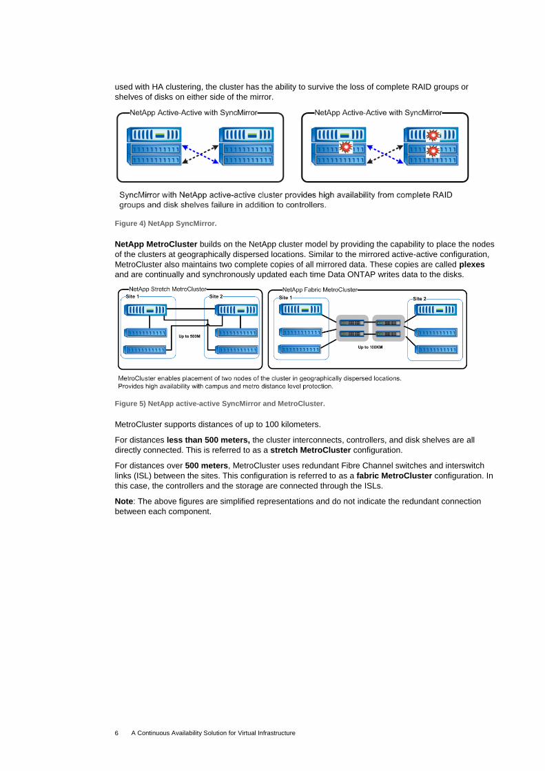
used with HA clustering, the cluster has the ability to survive the loss of complete RAID groups or
shelves of disks on either side of the mirror.
Figure 4) NetApp SyncMirror.
NetApp MetroCluster builds on the NetApp cluster model by providing the capability to place the nodes
of the clusters at geographically dispersed locations. Similar to the mirrored active-active configuration,
MetroCluster also maintains two complete copies of all mirrored data. These copies are called plexes
and are continually and synchronously updated each time Data ONTAP writes data to the disks.
Figure 5) NetApp active-active SyncMirror and MetroCluster.
MetroCluster supports distances of up to 100 kilometers.
For distances less than 500 meters, the cluster interconnects, controllers, and disk shelves are all
directly connected. This is referred to as a stretch MetroCluster configuration.
For distances over 500 meters, MetroCluster uses redundant Fibre Channel switches and interswitch
links (ISL) between the sites. This configuration is referred to as a fabric MetroCluster configuration. In
this case, the controllers and the storage are connected through the ISLs.
Note: The above figures are simplified representations and do not indicate the redundant connection
between each component.
A Continuous Availability Solution for Virtual Infrastructure 7
DIFFERENT TIERS OF PROTECTION WITH VMWARE VI3 WITH NETAPP STORAGE
Figure 6) VMware VI3 with NetApp storage.
DIFFERENT TIERS OF PROTECTION WITH VMWARE VSPHERE 4.0 WITH NETAPP STORAGE
Figure 7) VMware vSphere 4.0 with NetApp storage.
A Continuous Availability Solution for Virtual Infrastructure 8
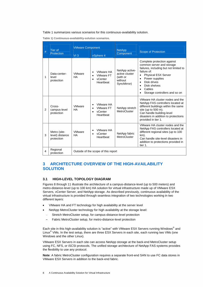
Table 1 summarizes various scenarios for this continuous-availability solution.
NetApp active-active cluster (with or without SyncMirror)
Complete protection against common server and storage failures, including but not limited to failure of:
Physical ESX Server
Power supplies
Disk drives
Disk shelves
Cables
Storage controllers and so on
2 Cross-campus-level protection
VMware HA
VMware HA
VMware FT
vCenter Heartbeat
NetApp stretch MetroCluster
VMware HA cluster nodes and the NetApp FAS controllers located at different buildings within the same site (up to 500 m). Can handle building-level disasters in addition to protections provided in tier 1.
3 Metro (site-level) distance protection
VMware HA
VMware HA
vCenter Heartbeat
NetApp fabric MetroCluster
VMware HA cluster nodes and the NetApp FAS controllers located at different regional sites (up to 100 km). Can handle site-level disasters in addition to protections provided in tier 1.
4 Regional protection
Outside of the scope of this report
3 ARCHITECTURE OVERVIEW OF THE HIGH-AVAILABILITY SOLUTION
3.1 HIGH-LEVEL TOPOLOGY DIAGRAM
Figures 8 through 11 illustrate the architecture of a campus-distance-level (up to 500 meters) and
metro-distance-level (up to 100 km) HA solution for virtual infrastructure made up of VMware ESX
Servers, vCenter Server, and NetApp storage. As described previously, continuous availability of the
virtual infrastructure is provided through seamless integration of two technologies working in two
different layers:
VMware HA and FT technology for high availability at the server level
NetApp MetroCluster technology for high availability at the storage level:
Stretch MetroCluster setup, for campus-distance-level protection
Fabric MetroCluster setup, for metro-distance-level protection
Each site in this high-availability solution is ―active‖ with VMware ESX Servers running Windows® and
Linux® VMs. In the test setup, there are three ESX Servers in each site, each running two VMs (one
Windows and the other Linux).
VMware ESX Servers in each site can access NetApp storage at the back-end MetroCluster setup
using FC, NFS, or iSCSI protocols. The unified storage architecture of NetApp FAS systems provides
the flexibility to use any protocol.
Note: A fabric MetroCluster configuration requires a separate front-end SAN to use FC data stores in
VMware ESX Servers in addition to the back-end fabric.
A Continuous Availability Solution for Virtual Infrastructure 9
TOPOLOGY DIAGRAM OF THE SOLUTION FOR VMWARE VIRTUAL INFRASTRUCTURE 3 (VI3)
Figure 8) VMware HA and NetApp stretch MetroCluster solution in VMware VI3.
A Continuous Availability Solution for Virtual Infrastructure 10
Figure 9) VMware HA and NetApp fabric MetroCluster solution in VMware VI3.
A Continuous Availability Solution for Virtual Infrastructure 11
TOPOLOGY DIAGRAM OF THE SOLUTION FOR VMWARE VSPHERE 4
Figure 10) VMware HA and FT and NetApp stretch MetroCluster solution in VMware vSphere 4.
A Continuous Availability Solution for Virtual Infrastructure 12
Figure 11) VMware HA and NetApp fabric MetroCluster solution in VMware vSphere 4.
A Continuous Availability Solution for Virtual Infrastructure 13
3.2 DEPLOYMENT DETAILS
MATERIAL LIST FOR HIGH-AVAILABILITY SETUP
Table 2) Material list for VMware VI3 and NetApp MetroCluster setup.
Infrastructure Component Vendor Quantity Details
Server Any As per VMware Compatibility Guide
Storage NetApp
NetApp storage systems—fabric and stretch MetroCluster config, RAID-DP For the currently supported matrix, see NetApp
support site.
Switch (fabric MetroCluster only, not required for stretch MetroCluster)
Brocade Four
Brocade Switch Model 200E 16P, Full Fabric, 4GB SWL SFPs For currently supported matrix, see NetApp support
site.
Switch (front-end SAN) Brocade Four Brocade Switch Model 3800
Network Adapter Broadcom Two per server
Broadcom NetXtreme II BCM 5708 1000Base-T
HBA QLogic Two per server
QLogic QLA 2432 A minimum of 2 HBAs are required in a production environment.
Software NetApp
Data ONTAP 7.2.4 or higher See section 4.2 and the VMware KB article VMware
VI3 Support with NetApp MetroCluster.
NetApp cluster_remote
NetApp syncMirror_local
VMware VMware ESX Server 3.5 U3 or later
VMware VMware vCenter Server 2.5U4 or later
Table 3) Material list for VMware vSphere 4 and NetApp MetroCluster setup.
Infrastructure Component Vendor Quantity Details
Server Any
As per VMware FT Compatibility Guide, hosts must have FT-compatible processors. Also see the VMware KB article on FT-compatible processor.
Storage NetApp
NetApp storage systems—fabric and stretch MetroCluster config, RAID-DP. For currently supported matrix, see NetApp support
site.
Switch (fabric MetroCluster only, not required for stretch MetroCluster)
Brocade Four
Brocade Switch Model 200E 16P, Full Fabric, 4GB SWL SFPs For currently supported matrix, see the NetApp
support site.
Switch (front-end SAN) Brocade Four Brocade Switch Model 3800
Network Adapter Broadcom Two per server
Broadcom NetXtreme II BCM 5708 1000Base-T See VMware Fault Tolerance recommendations and
Considerations on VMware vSphere 4.
HBA QLogic Two per server
QLogic QLA 2432 A minimum of two HBAs are required in a production environment.
BROCADE SWITCH CONNECTION DETAILS AND CONFIGURATION TABLES
Figure 14) Brocade switch connection details in fabric MetroCluster setup.
For connection details on the Brocade switch in a MetroCluster setup, see Appendix B.
A Continuous Availability Solution for Virtual Infrastructure 16
4 SETUP AND CONFIGURATION OF THE CONTINUOUS-AVAILABILITY SOLUTION
4.1 NETAPP STORAGE CONFIGURATION
BEST PRACTICE: Set the Data ONTAP configuration option cf.takeover.change_fsid to
OFF. This option is supported on Data ONTAP version 7.2.4 and higher.
In the event of complete storage controller and/or all disk shelves failure (storage controller and associated local disk shelves), a manual failover of the MetroCluster should be performed. If the change_fsid option is set to OFF on a NetApp FAS storage controller running Data
ONTAP version 7.2.4 or higher, after performing a manual MetroCluster failover, the UUIDs of the mirrored LUNs are retained and additional steps in the ESX Server side are not required to detect the VMFS volumes. Once the VMFS volumes are detected, the VMs can be manually powered on.
On NetApp FAS storage controllers running Data ONTAP older than 7.2.4, after performing a manual MetroCluster failover, the mirrored LUNs do not maintain the same LUN UUID as the original LUNs because this option is not available. When these LUNs house the VMFS-3 file system, the volumes are detected by ESX Server 3.x as being on Snapshot
™ LUNs. Similarly,
if a RAW LUN that is mapped as an RDM (Raw Device Mapping) is replicated or mirrored through MetroCluster, the metadata entry for the RDM must be recreated to map to the replicated or mirrored LUN. To make sure the ESX hosts have access to the VMFS volumes on the mirrored LUNs, see VMware KB 1001783.
Figure 15) Set the cf.takeover.change_fsid configuration to OFF.
The FAS controllers should be licensed with the following features:
cluster, cluster_remote, syncmirror_local
iscsi, fcp, nfs
MetroCluster setup with software-based disk ownership for the NetApp FAS controllers with the
Brocade switches is performed in accordance with the guidelines provided by:
Data ONTAP 7.3 Active-Active Configuration Guide (part number: 210-04192_A0): http://now.netapp.com/NOW/knowledge/docs/ontap/rel7311/pdfs/ontap/aaconfig.pdf
Brocade 200E Switch Configuration Guide
MetroCluster Design and Implementation Guide: http://media.netapp.com/documents/tr-3548.pdf
In the FAS controllers on both sites, flexible volumes are created inside the same aggregate
corresponding to two types of ESX data stores: VMFS (FC and iSCSI) and NFS.
Figure 16 depicts the physical and logical storage configuration of a NetApp MetroCluster setup as viewed from any of the sites.
BEST PRACTICE: See NetApp and VMware Virtual Infrastructure 3 Best Practices and NetApp and
VMware vSphere 4 Best Practices for best practices related to creating aggregates, NFS, and VMFS data stores on NetApp FAS systems for VMware VI 3 and vSphere 4, respectively.
VMware vSphere introduces a number of new features and capabilities to virtual networking through VMware vNetwork. The most important enhancement to VMware vNetwork is the VMware vNetwork Distributed Switch (vDS). The VMware vNetwork Distributed Switch provides a centralized point of
control for cluster-level networking and moves beyond per-host network configurations in virtual environments to simplify and enhance virtual machine networking:
Simplified provisioning and administration of virtual networking across many hosts and clusters
through a centralized interface
Simplified end-to-end physical and virtual network management through third-party virtual switch extensions for the Cisco Nexus 1000V virtual switch
Enhanced provisioning and traffic management capabilities through private VLAN support and
bidirectional virtual machine rate limiting
Enhanced security and monitoring for virtual machines migrated via VMware VMotion™
through
maintenance and migration of the port run-time state. In VMware VI3 and prior releases, virtual networks were constructed using virtual switches or vSwitches on each individual ESX hosts. In addition to continuing support for the vSwitch (known as the Standard
A Continuous Availability Solution for Virtual Infrastructure 18
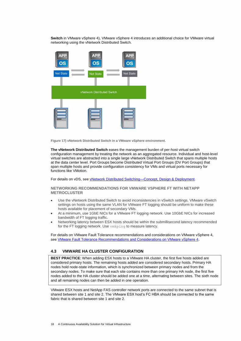
Switch in VMware vSphere 4), VMware vSphere 4 introduces an additional choice for VMware virtual
networking using the vNetwork Distributed Switch.
Figure 17) vNetwork Distributed Switch in a VMware vSphere environment.
The vNetwork Distributed Switch eases the management burden of per-host virtual switch
configuration management by treating the network as an aggregated resource. Individual and host-level virtual switches are abstracted into a single large vNetwork Distributed Switch that spans multiple hosts at the data center level. Port Groups become Distributed Virtual Port Groups (DV Port Groups) that span multiple hosts and provide configuration consistency for VMs and virtual ports necessary for functions like VMotion. For details on vDS, see vNetwork Distributed Switching—Concept, Design & Deployment.
NETWORKING RECOMMENDATIONS FOR VMWARE VSPHERE FT WITH NETAPP METROCLUSTER
Use the vNetwork Distributed Switch to avoid inconsistencies in vSwitch settings. VMware vSwitch
settings on hosts using the same VLAN for VMware FT logging should be uniform to make these hosts available for placement of secondary VMs.
At a minimum, use 1GbE NICs for a VMware FT logging network. Use 10GbE NICs for increased bandwidth of FT logging traffic.
Networking latency between ESX hosts should be within the submillisecond latency recommended
for the FT logging network. Use vmkping to measure latency.
For details on VMware Fault Tolerance recommendations and considerations on VMware vSphere 4,
see VMware Fault Tolerance Recommendations and Considerations on VMware vSphere 4.
4.3 VMWARE HA CLUSTER CONFIGURATION
BEST PRACTICE: When adding ESX hosts to a VMware HA cluster, the first five hosts added are
considered primary hosts. The remaining hosts added are considered secondary hosts. Primary HA
nodes hold node-state information, which is synchronized between primary nodes and from the
secondary nodes. To make sure that each site contains more than one primary HA node, the first five
nodes added to the HA cluster should be added one at a time, alternating between sites. The sixth node
and all remaining nodes can then be added in one operation.
VMware ESX hosts and NetApp FAS controller network ports are connected to the same subnet that is
shared between site 1 and site 2. The VMware ESX host‘s FC HBA should be connected to the same
A Continuous Availability Solution for Virtual Infrastructure 19
4.4 VMWARE FT CLUSTER CONFIGURATION (FOR VSPHERE 4)
To enable VMware Fault Tolerance in the VMware HA cluster, do the following:
Enable host certificate checking (if upgrading from a previous version of virtual infrastructure).
Configure networking for each host.
Create the VMware HA cluster, add hosts, and check compliance.
VMware Fault Tolerance can be turned on from the vCenter Server (the minimum permission requirement is an account having cluster administrator permissions):
1. Select the Hosts & Clusters view. 2. Right-click a virtual machine and select Fault Tolerance > ‗Turn On‘ Fault Tolerance. 3. The specified virtual machine is designated as a Primary VM and a Secondary VM is established
on another host. The Primary VM is now fault tolerant.
To know more about the installation and configuration of vSphere Availability (HA and FT), see vSphere Availability Guide.
4.5 SETUP AND CONFIGURATION OPTIONS FOR THE VCENTER SERVER
OPTION 1 (FOR BOTH VMWARE VI3 AND VSPHERE 4)
In this setup, the VMware vCenter Server runs inside a virtual machine (non-FT) in the HA cluster.
Another way of designing the vCenter Server is to place it in a physical MSCS cluster with an MSCS
cluster node in each site. If the storage housing the vCenter MSCS instance is at the failed site, it is
necessary to perform the NetApp CFOD recovery. First recover the MSCS and start vCenter; then
continue with the recovery process.
For details on the deployment of vCenter Server with MSCS cluster, see
www.vmware.com/pdf/VC_MSCS.pdf.
OPTION 2—BEST PRACTICE: VMWARE VCENTER HEARTBEAT (ONLY FOR VSPHERE 4)
Because the VMware vCenter Server is used to manage many tier-1 applications, it renders itself as a tier-1 application. Therefore, it becomes very important for the VMware vCenter Server to be highly available. This is where VMware vCenter Server Heartbeat steps in. VMware vCenter Server Heartbeat delivers high availability for the VMware vCenter Server management platform, for consistent operation of the VMware vSphere environment. Architecturally, vCenter Server Heartbeat is implemented on active-passive vCenter Server clones running on physical or virtual machines. In addition to server and network hardware, vCenter Server Heartbeat monitors the actual vCenter Server instance, its back-end database, and the underlying operating system. In case of failure, the passive node takes over and the vCenter Server Heartbeat software restarts the vCenter service. Failover can occur on both LANs and WANs. To know more about the installation and configuration of VMware vCenter Server Heartbeat, see VMware vCenter Server Heartbeat.
vCenter Server Heartbeat protects VMware vCenter Server availability by monitoring all components of VMware vCenter Server, including VMware License Server and other plug-ins
Minimizes downtime of critical functions such as VMware VMotion and VMware DRS
Protects VMware vCenter Server performance, alerts, and events information, keeping it up to date even if the VMware vCenter Server experiences an outage
Provides automatic failover and failback of VMware vCenter Server
Enables administrators to schedule maintenance windows and maintain availability by initiating a manual switchover to the standby server
Protects and recovers the VMware vCenter Server database
Protects critical configuration, inventory, and other information stored in the VMware vCenter Server database, even if the database is installed on a separate server
Figure 18 illustrates the vCenter Server Heartbeat configuration used for this solution. The primary and the secondary vCenter Server VMs are deployed on separate ESX servers in separate sites and use
A Continuous Availability Solution for Virtual Infrastructure 20
separate data stores from the local NetApp storage controller in the MetroCluster configuration. The vCenter Server Heartbeat channel is configured over the LAN across the sites.
Figure 18) Center server heartbeat deployment.
5 CONTINUOUS-AVAILABILITY SOLUTION TESTS IN DIFFERENT FAILURE SCENARIOS
Note: The tests below are executed for continuous availability with both stretch and fabric MetroCluster
setups for VMware VI3 as well as vSphere 4 environments unless otherwise specifically stated. The terms ―Site 1,‖ ―Local Site,‖ and ―Failed Site‖ can be used interchangeably. The terms ―Site 2‖ and ―Remote Site‖ can be used interchangeably. Refer to figures in the High-Level Topology Diagram section for the component‘s name, location,
and connectivity.
5.1 FAILURES WITHIN A DATA CENTER
OPERATIONAL SCENARIO 1: COMPLETE LOSS OF POWER TO DISK SHELF
Tests Performed
1. Power off one disk shelf.
2. Observe the result.
3. Power it back on.
Expected Results
Relevant disks go offline; plex is broken.
No disruption to data availability for hosts containing FT and non-FT (only HA) VMs.
No change detected in the ESX Server level and FT and non-FT VMs run without any interruption.
When power is returned to the shelf, the disks are detected. A resync of the plexes occurs without any manual action.
A Continuous Availability Solution for Virtual Infrastructure 21
Actual Results
Actual results were in line with the expected behavior, and the tests passed as expected.
MetroCluster Behavior
No MetroCluster event
VMware HA Behavior
No HA event
VMware FT Behavior
No FT event
Impact to Data Availability
None
OPERATIONAL SCENARIO 2: LOSS OF ONE LINK IN ONE DISK LOOP
Tests Performed
1. Disconnect the fiber cable on one of the disk shelves.
2. Observe the results.
3. Reconnect the fiber.
Expected Results
No disruption to data availability on hosts containing FT and non-FT (only HA) VMs.
The controller displays the message that some disks are connected to only one switch.
No change detected in the ESX Server level and VMs run without any interruption.
When the fiber is reconnected, the controller displays the messages that disks are now connected to two switches.
Actual Results Actual results were in line with the expected behavior, and the tests passed as expected.
MetroCluster Behavior
No MetroCluster event
VMware HA Behavior
No HA event
VMware FT Behavior
No FT event
Impact to Data Availability
None
A Continuous Availability Solution for Virtual Infrastructure 22
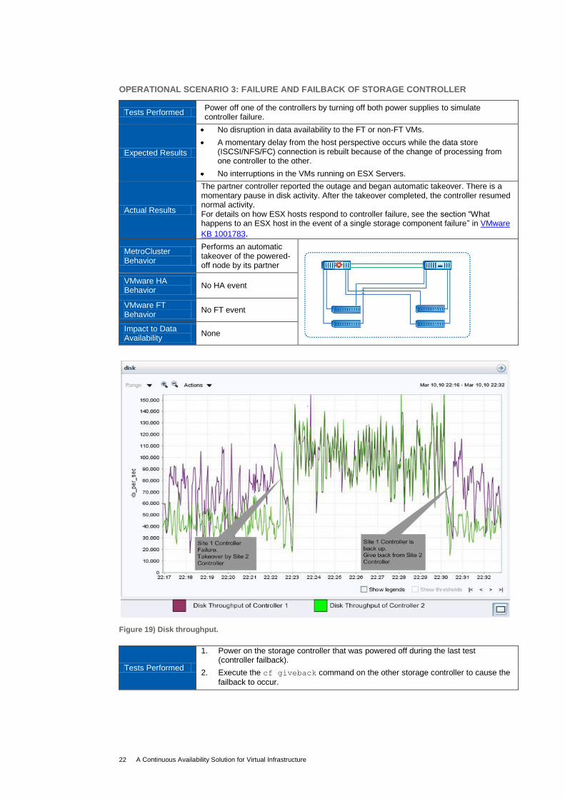
OPERATIONAL SCENARIO 3: FAILURE AND FAILBACK OF STORAGE CONTROLLER
Tests Performed Power off one of the controllers by turning off both power supplies to simulate controller failure.
Expected Results
No disruption in data availability to the FT or non-FT VMs.
A momentary delay from the host perspective occurs while the data store (ISCSI/NFS/FC) connection is rebuilt because of the change of processing from one controller to the other.
No interruptions in the VMs running on ESX Servers.
Actual Results
The partner controller reported the outage and began automatic takeover. There is a momentary pause in disk activity. After the takeover completed, the controller resumed normal activity. For details on how ESX hosts respond to controller failure, see the section ―What happens to an ESX host in the event of a single storage component failure‖ in VMware
KB 1001783.
MetroCluster Behavior
Performs an automatic takeover of the powered- off node by its partner
VMware HA Behavior
No HA event
VMware FT Behavior
No FT event
Impact to Data Availability
None
Figure 19) Disk throughput.
Tests Performed
1. Power on the storage controller that was powered off during the last test (controller failback).
2. Execute the cf giveback command on the other storage controller to cause the
A Continuous Availability Solution for Virtual Infrastructure 23
Expected Results
No disruption to data availability to the FT and non-FT VMs.
There is a momentary drop in disk activity as indicated in the graph above. A slight delay from the host perspective occurs while the data store (ISCSI/NFS/FC) connection is rebuilt because of the change of processing from one controller to the other.
No interruptions occur in the VMs running on the ESX Servers.
Actual Results
Actual results were in line with the expected behavior, and the tests passed as expected. For details on how ESX hosts respond to controller failback, see the section ―What happens to an ESX host in the event of a single storage component failure?‖ in
VMware KB 1001783.
MetroCluster Behavior
Controller in failed site reclaims its original role prior to failure; there is no disruption to storage access to either site.
A Continuous Availability Solution for Virtual Infrastructure 24
Actual Results
Actual results were in line with the expected behavior, and the tests passed as expected.
MetroCluster Behavior
When the plex is broken, the other site serves all data from the surviving disk shelves.
VMware HA Behavior
VMs previously running in the failed hosts are automatically powered on in the surviving nodes.
VMware FT Behavior
Protects the VM (primary) by making the secondary VM as primary, and then calls HA to create a secondary copy on another node.
Impact to Data Availability
None
OPERATIONAL SCENARIO 6: TOTAL ESX HOST FAILURE AT ONE SITE
Tests Performed Power off all ESX hosts at site 1.
Expected Results
No disruption to data availability for the surviving ESX hosts containing FT and non-FT VMs.
The secondary FT VMs come online and act as primary FT VMs, and one more secondary FT VM is created in the HA cluster.
Non-FT HA-enabled VMs migrate to other ESX servers in the cluster and boot up.
Actual Results Actual results were in line with the expected behavior, and the tests passed as expected.
MetroCluster Behavior
No MetroCluster event
VMware HA Behavior
VMs previously running in the failed hosts are automatically powered on in the surviving nodes.
VMware FT Behavior
Protects VM (primary) by making the secondary VM as primary and then creating a secondary copy on another node.
Impact to Data Availability
None
OPERATIONAL SCENARIO 7: LOSS OF ONE BROCADE FABRIC INTERCONNECT SWITCH (APPLICABLE ONLY FOR HA SOLUTIONS WITH FABRIC METROCLUSTER SETUP)
Tests Performed
1. Power off one of the Fibre Channel switches in site 1.
2. Observe the results.
3. Power it back on.
Expected Results
There is no disruption to data availability.
The controller displays the message that some disks are connected to only one switch and that one of the cluster interconnects is down.
No change is detected in the ESX Server level and VMs run without any interruption.
When power is restored and the switch completes its boot process, the controller displays messages to indicate that the disks are now connected to two switches
A Continuous Availability Solution for Virtual Infrastructure 25
and that the second cluster interconnect is again active.
Actual Results Actual results were in line with the expected behavior and the tests passed as expected.
MetroCluster Behavior
No MetroCluster event
VMware HA Behavior
No HA event
VMware FT Behavior
No FT event
Impact to Data Availability
None
OPERATIONAL SCENARIO 8: LOSS OF ONE ISL BETWEEN THE BROCADE FABRIC INTERCONNECT SWITCHES (APPLICABLE ONLY FOR HA SOLUTIONS WITH FABRIC METROCLUSTER SETUP)
Tests Performed Remove the ISL fiber cable between the Brocade fabric interconnect switches.
Expected Results
There is no disruption to data availability.
The controller displays the message that some disks are connected to only one switch and that one of the cluster interconnects is down.
No change is detected in the ESX Server level, and VMs run without any interruption.
When ISL is reconnected, the controller displays messages to indicate that the disks are now connected to two switches and that the second cluster interconnect is again active.
Actual Results Actual results were in line with the expected behavior, and the tests passed as expected.
MetroCluster Behavior
No MetroCluster event
VMware HA Behavior
No HA event
VMware FT Behavior
No FT event
Impact to Data Availability
None
A Continuous Availability Solution for Virtual Infrastructure 26
5.2 FAILURES THAT AFFECT AN ENTIRE DATA CENTER
OPERATIONAL SCENARIO 9: LOSS OF AN ENTIRE SITE
In case of a complete site-level disaster, all physical components of the VMware HA and FT and
NetApp MetroCluster solution such as VMware ESX Servers, NetApp storage controllers, and
associated disk shelves can become unavailable simultaneously. In such circumstances, a manual
failover of the NetApp MetroCluster needs to be performed.
One way to simulate a real-world site disaster in the lab is to interrupt the components of the lab setup
in the order given so that the partner site component is unable to automatically detect any failure.
To simulate a site 1 disaster, do the following:
Step # Description
1
Disconnect both Cluster Interconnect (CI) cables at site 1 (in the case of a stretch
MetroCluster).
Or
Disconnect both ISLs at site 1 (in the case of a fabric MetroCluster).
2 Remove the power from all disk shelves in site 1.
3 Remove power from all ESX Servers in site 1.
4 Remove power from the NetApp storage controller in site 1.
Figure 20) Loss of an entire site.
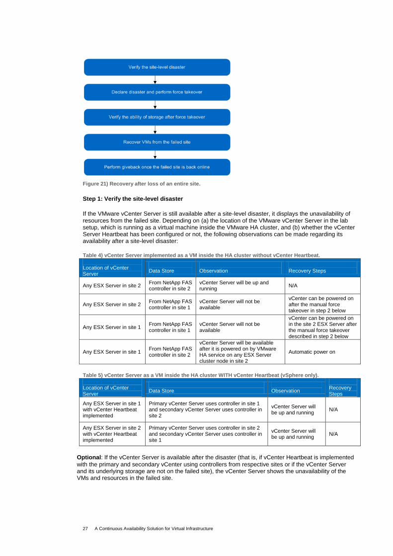
Figure 21 illustrates the recovery process involved in a complete site loss scenario.
A Continuous Availability Solution for Virtual Infrastructure 27
Figure 21) Recovery after loss of an entire site.
Step 1: Verify the site-level disaster
If the VMware vCenter Server is still available after a site-level disaster, it displays the unavailability of resources from the failed site. Depending on (a) the location of the VMware vCenter Server in the lab setup, which is running as a virtual machine inside the VMware HA cluster, and (b) whether the vCenter Server Heartbeat has been configured or not, the following observations can be made regarding its availability after a site-level disaster:
Table 4) vCenter Server implemented as a VM inside the HA cluster without vCenter Heartbeat.
Location of vCenter Server
Data Store
Observation
Recovery Steps
Any ESX Server in site 2 From NetApp FAS controller in site 2
vCenter Server will be up and running
N/A
Any ESX Server in site 2 From NetApp FAS controller in site 1
vCenter Server will not be available
vCenter can be powered on after the manual force takeover in step 2 below
Any ESX Server in site 1 From NetApp FAS controller in site 1
vCenter Server will not be available
vCenter can be powered on in the site 2 ESX Server after the manual force takeover described in step 2 below
Any ESX Server in site 1 From NetApp FAS controller in site 2
vCenter Server will be available after it is powered on by VMware HA service on any ESX Server cluster node in site 2
Automatic power on
Table 5) vCenter Server as a VM inside the HA cluster WITH vCenter Heartbeat (vSphere only).
Location of vCenter Server
Data Store
Observation
Recovery Steps
Any ESX Server in site 1 with vCenter Heartbeat implemented
Primary vCenter Server uses controller in site 1 and secondary vCenter Server uses controller in site 2
vCenter Server will be up and running
N/A
Any ESX Server in site 2 with vCenter Heartbeat implemented
Primary vCenter Server uses controller in site 2 and secondary vCenter Server uses controller in site 1
vCenter Server will be up and running
N/A
Optional: If the vCenter Server is available after the disaster (that is, if vCenter Heartbeat is implemented
with the primary and secondary vCenter using controllers from respective sites or if the vCenter Server and its underlying storage are not on the failed site), the vCenter Server shows the unavailability of the VMs and resources in the failed site.
A Continuous Availability Solution for Virtual Infrastructure 28
Figure 22) VM status.
The storage controller in the surviving site (site 2) shows that its partner node is down. As mentioned previously, during an entire site failure an automated cluster takeover will not be initiated by the surviving storage controller node.
Step 2: Declare disaster and perform force takeover
Declare a site disaster and perform a manual takeover at the surviving site (site 2) by issuing the
following command in the NetApp storage controller of site 2:
cf forcetakeover -d
Step 3: Verify availability of storage after force takeover
After executing the cf forcetakeover command, all LUNs and NFS exports of the failed node will
be automatically available.
Step 4: Automatic power on of virtual machines in remote site
Note: In this specific test scenario, the disaster is planned with immediate declaration; therefore, the
active storage in the failed site is made available almost immediately to the ESX Server hosts in the
surviving site. In real site disaster scenarios, the declaration may not be immediate. Therefore, the
virtual machines may need to be manually powered on in the surviving site after storage is made
available through the forced takeover.
Takeover is successful and the virtual machines are automatically powered on in the surviving ESX
Server on the remote site.
If the vCenter Server is down, it will now boot in a surviving ESX Server and can be accessed.
A Continuous Availability Solution for Virtual Infrastructure 29
Figure 23) VM status.
From this point, all VMs in the ESX Servers at the failed site get powered on and start running
normally. For FT-enabled VMs, both primary and secondary are created on two separate nodes in
the surviving site and the VMs restart. Similarly the HA-enabled (non-FT) VMs restart on the
available cluster nodes of the surviving site.
This completes the takeover process for site-level disasters.
Step 5: Perform giveback once the failed site is back online
1. Power on all disk shelves connected to the storage controller of site 1.
2. Reconnect the cluster interconnect between sites so that the storage controller in site 2 can see the
disk shelves from site 1. After connection, the disk shelves from either side automatically begin to
resync.
3. All ESX Servers in site 1 are now powered on. When the ESX Servers are online, power on the
storage controller in site 1.
4. Use the cf status command to verify that a giveback is possible and verify that all mirror
resynchronization is complete before proceeding with the cf giveback command.
5. If necessary, perform manual migration of virtual machines from the surviving site to the restored
failed site with their respective ESX Servers.
This completes the giveback process.
5.3 COMBINATION TESTS (FAILURES THAT AFFECT BOTH SITES)
OPERATIONAL SCENARIO 10-1: COMBINATION TEST (ESX HOST SERVER AND CONTROLLER FAILURE ACROSS SITES)
Tests Performed 1. Power off all ESX hosts at site 1.
2. Power off the storage controller at site 2.
Expected Results
Controller at site 1 automatically takes over the powered-off controller.
There is no disruption to data availability for surviving hosts containing the FT and non-FT VMs.
The secondary FT VMs come online and start acting as primary FT VMs and new secondary FT VMs are created in the surviving FT-enabled HA cluster nodes.
Non-FT HA-enabled VMs are migrated to other ESX Servers in the cluster and restart.
A Continuous Availability Solution for Virtual Infrastructure 30
Actual Results Actual results were in line with the expected behavior, and the tests passed as expected.
MetroCluster Behavior
Partner controller in site 1 performs an automatic takeover.
VMware HA Behavior
VMs previously running in the failed hosts are automatically powered on in the surviving nodes.
VMware FT Behavior
Protects VM (primary) by making the secondary VM primary and then creating a secondary copy on another node
Impact to Data Availability
None
OPERATIONAL SCENARIO 10-2: COMBINATION TEST (DISK SHELVES FAILURE IN BOTH SITES)
Tests Performed 1. Power off disk pool 0 in site 1.
2. Power off disk pool 0 in site 2.
Expected Results VMs should not detect any changes and continue to operate normally.
Actual Results Actual results were in line with the expected behavior, and the tests passed as expected.
MetroCluster Behavior
No MetroCluster event. Data is served from the mirrored copy.
VMware HA Behavior
No HA event
VMware FT Behavior
No FT event
Impact to Data Availability
None
OPERATIONAL SCENARIO 10-3: COMBINATION TEST (CONTROLLLER AND DISK SHELF FAILURE
Tests Performed 1. Power off storage controller in site 1.
2. Power off disk pool 0 in site 2.
Expected Results VMs should not detect any changes and should continue to operate normally.
Actual Results Actual results were in line with the expected behavior, and the tests passed as expected.
A Continuous Availability Solution for Virtual Infrastructure 31
6 SUMMARY
Figure 24) Summary of failure scenarios and the impact on data availability.
# Failure Scenario Data Availability Impact
1 Complete loss of power to disk shelf None
2 Loss of one link in one disk loop None
3 Failure and failback of storage controller None
4 Loss of mirrored storage or network isolation None
5 Total network isolation, including all ESX hosts (FT or non-FT enabled) and loss of hard drive
Applications or data in the non-FT VMs running on the ESX Servers before they were powered off will be available after they automatically come up in the surviving nodes of the VMware HA cluster. FT-enabled VMs will run uninterrupted.
6 Loss of all ESX Servers in one site
Applications or data in the non-FT VMs running on the ESX Servers before they were powered off will be available after they automatically come up in the surviving nodes of the VMware HA cluster. FT-enabled VMs will run uninterrupted.
7 Loss of one Brocade Fabric Interconnect switch (applicable for continuous availability solution with fabric MetroCluster only)
None
8
Loss of one ISL between the Brocade Fabric Interconnect switches (applicable for continuous-availability solution with fabric MetroCluster only)
None
9 Loss of an entire site
Applications or data in the VMs (both FT enabled and non-FT) and running in the failed site will be
available after executing the force takeover
command from the surviving site.
10-1 Loss of all ESX Servers in one site and loss of storage controller in the other site
None
10-2 Loss of disk pool 0 in both sites None
10-3 Loss of storage controller in one site and loss of disk pool 0 in the other
None
VMware HA, FT, and NetApp MetroCluster technologies can work in synergy to provide a simple and robust continuous-availability solution for planned and unplanned downtime in virtual data center environments.
Planned site and component failovers, at both the server and storage level, can be triggered without disrupting the environment, thus allowing scheduled maintenance without any downtime. Similarly this solution delivers complete protection against unplanned server and storage failures, including failure of the physical ESX Server, NetApp storage controller, power supplies, disk drives, disk shelves, cables, and so on.
This paper is not intended to be a definitive implementation or solutions guide for continuous-availability solutions in VMware vSphere 4 and Virtual Infrastructure 3 (VI3) with NetApp storage. Many factors related to specific customer environments are not addressed in this document. Contact NetApp Support to speak with one of our virtualization solutions experts for any deployment requirement.
A Continuous Availability Solution for Virtual Infrastructure 32
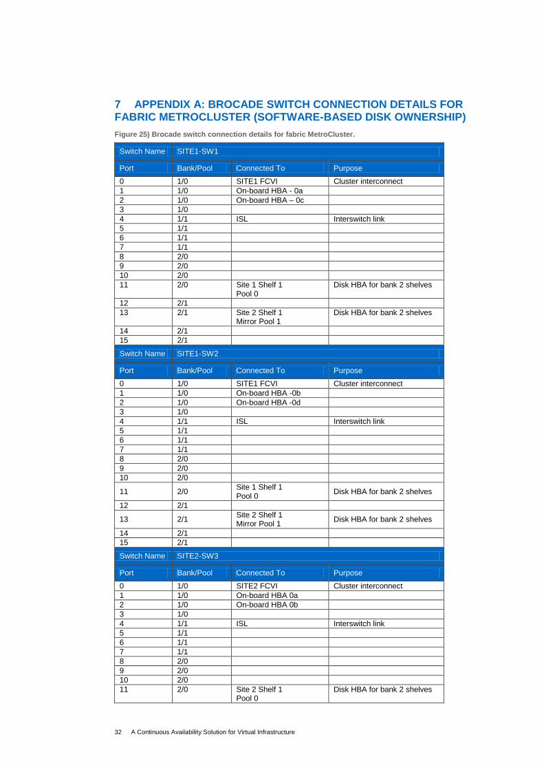
7 APPENDIX A: BROCADE SWITCH CONNECTION DETAILS FOR FABRIC METROCLUSTER (SOFTWARE-BASED DISK OWNERSHIP)
Figure 25) Brocade switch connection details for fabric MetroCluster.
Switch Name SITE1-SW1
Port Bank/Pool Connected To Purpose
0 1/0 SITE1 FCVI Cluster interconnect
1 1/0 On-board HBA - 0a
2 1/0 On-board HBA – 0c
3 1/0
4 1/1 ISL Interswitch link
5 1/1
6 1/1
7 1/1
8 2/0
9 2/0
10 2/0
11 2/0 Site 1 Shelf 1 Pool 0
Disk HBA for bank 2 shelves
12 2/1
13 2/1 Site 2 Shelf 1 Mirror Pool 1
Disk HBA for bank 2 shelves
14 2/1
15 2/1
Switch Name SITE1-SW2
Port Bank/Pool Connected To Purpose
0 1/0 SITE1 FCVI Cluster interconnect
1 1/0 On-board HBA -0b
2 1/0 On-board HBA -0d
3 1/0
4 1/1 ISL Interswitch link
5 1/1
6 1/1
7 1/1
8 2/0
9 2/0
10 2/0
11 2/0 Site 1 Shelf 1 Pool 0
Disk HBA for bank 2 shelves
12 2/1
13 2/1 Site 2 Shelf 1 Mirror Pool 1
Disk HBA for bank 2 shelves
14 2/1
15 2/1
Switch Name SITE2-SW3
Port Bank/Pool Connected To Purpose
0 1/0 SITE2 FCVI Cluster interconnect
1 1/0 On-board HBA 0a
2 1/0 On-board HBA 0b
3 1/0
4 1/1 ISL Interswitch link
5 1/1
6 1/1
7 1/1
8 2/0
9 2/0
10 2/0
11 2/0 Site 2 Shelf 1 Pool 0
Disk HBA for bank 2 shelves
A Continuous Availability Solution for Virtual Infrastructure 33
12 2/1
13 2/1 Site 1 Shelf 1 Mirror Pool 1
Disk HBA for bank 2 shelves
14 2/1
15 2/1
Switch Name SITE2-SW4
Port Bank/Pool Connected To Purpose
0 1/0 SITE2 FCVI Cluster Interconnect
1 1/0 On-board 0b
2 1/0 On-board 0d
3 1/0
4 1/1 ISL Interswitch link
5 1/1
6 1/1
7 1/1
8 2/0
9 2/0
10 2/0
11 2/0 Site 2 Shelf 1 Pool 0
Disk HBA for bank 2 shelves
12 2/1
13 2/1 Site 1 Shelf 1 Mirror Pool 1
Disk HBA for bank 2 shelves
14 2/1
15 2/1
A Continuous Availability Solution for Virtual Infrastructure 34
8 APPENDIX B: MATERIALS USED IN THE LAB SETUP
Figure 26) Lab setup.
Infrastructure Component
Vendor Quantity Details
Server IBM
1 IBM x3550 server
5 IBM x3650 server
Intel® Xeon™ Processor (Intel-VT), CPU: 74 GHz total in the cluster Memory: 52GB total in the cluster
A Continuous Availability Solution for Virtual Infrastructure 36
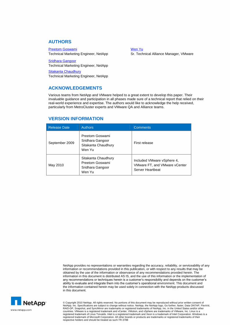
AUTHORS
Preetom Goswami
Technical Marketing Engineer, NetApp
Wen Yu
Sr. Technical Alliance Manager, VMware
Sridhara Gangoor
Technical Marketing Engineer, NetApp
Sitakanta Chaudhury
Technical Marketing Engineer, NetApp
ACKNOWLEDGEMENTS
Various teams from NetApp and VMware helped to a great extent to develop this paper. Their invaluable guidance and participation in all phases made sure of a technical report that relied on their real-world experience and expertise. The authors would like to acknowledge the help received, particularly from MetroCluster experts and VMware QA and Alliance teams.
VERSION INFORMATION
Release Date Authors Comments
September 2009
Preetom Goswami
Sridhara Gangoor
Sitakanta Chaudhury
Wen Yu
First release
May 2010
Sitakanta Chaudhury
Preetom Goswami
Sridhara Gangoor
Wen Yu
Included VMware vSphere 4,
VMware FT, and VMware vCenter
Server Heartbeat
NetApp provides no representations or warranties regarding the accuracy, reliability, or serviceability of any information or recommendations provided in this publication, or with respect to any results that may be obtained by the use of the information or observance of any recommendations provided herein. The information in this document is distributed AS IS, and the use of this information or the implementation of any recommendations or techniques herein is a customer‘s responsibility and depends on the customer‘s ability to evaluate and integrate them into the customer‘s operational environment. This document and the information contained herein may be used solely in connection with the NetApp products discussed in this document.