27
No.:EX##−OMH0025 Technical specification Output block / Power block EX9-OET1 EX9-OET2 EX9-OEP1 EX9-OEP2 EX9-PE1
No.:EX##−OMH0025
Technical specification
Output block / Power block EX9-OET1 EX9-OET2 EX9-OEP1 EX9-OEP2 EX9-PE1
- 1 - EX## OMH0025
Table of Contents
1.Safety instructions P2
2.Model P102-1.Output block for low wattage load P102-2.Output block for high wattage load P102-3.Power block P112-4.Accessory cable P122-5.Option P13
3.Specifications P143-1.General specifications P143-2.Electric specifications P143-3.Applicable SI unit / solenoid valve series P14
4.Wiring and Setting P154-1.Output connector and circuit construction P154-2.Power wiring P184-3.Installation and maintenance P19
5.LED Display and Dimensions P205-1 LED display P205-2 Dimensions P21
6.Troubleshooting P22
7.Attachment P23
- 2 - EX## OMH0025
1.Safety instructionsThis manual contains essential information for the protection of users and others from possible injury and damage to property and to ensure correct handling. Please confirm that you fully understand the meaning of the following messages (signs) before reading the remaining text, and always follow the instructions. Also carefully read the instruction manual for any relevant equipment or apparatus before use.
♦Indications
IMPORTANT MESSAGES Read this manual and follow the instructions. Signal words such as WARNING, CAUTION and NOTE, will be followed by important safety information that must be carefully reviewed.
Indicates a potentially hazardous situation which could result in death or serious injury if you do not follow instructions.
Indicates a potentially hazardous situation which if not avoided, may result in minor injury or moderate injury.
NOTE Provides helpful information.
♦Operator ♦This manual has been written for those who have knowledge of machinery and apparatuses
that use pneumatic equipment and have full knowledge of assembly, operation and maintenance of such equipment.
♦Please carefully read and understand this manual before assembling, operating or performing maintenance on the product presented in this manual (output block and power block).
♦ Usage Restrictions
♦This product is designed to be used in general equipment for factory automation. Never use this product with an equipment or apparatus that directly concerns human life*1 or in which a malfunction or failure can cause a great loss. *1: Equipment or apparatus that directly concerns human life refers to means the following: • Medical equipment such as life support systems or equipment used in operating rooms • Compulsory equipment required by law such as the Fire Prevention Law, Construction Law, etc. • Equipment or apparatus that conforms with those mentioned above.
♦Contact our sales department when the product is planned to be used for a system*2 or equipment that concerns the safety of persons or that seriously affects the public. Such usuage requires special consideration*3. *2: A system or equipment that concerns the safety of persons or that seriously affects the public refers
to the following: • Nuclear reactor control system in a nuclear power plant, safety protection systems or other systems
important for safety in a nuclear power facility. • Driving control system for a mass transportation system, and flight control systems • Equipment or apparatuses that comes in contact with foods or beverages
*3: Special consideration refers to discussing the usage with our engineers to establish a safe system which is designed as foolproof, fail-safe, redundant etc.
♦Special consideration*4 should be taken regarding safety or maintainability to prevent a failure or malfunction which can cause a hazard or loss. This is likely to occur under certain environmental stresses (deterioration). *4: Special consideration means fully review of the equipment or apparatus during the design stage and
establishing of a backup system in advance, such as a redundant system or fail-safe system.
- 3 - EX## OMH0025
♦Do not disassemble, modify (including printed circuit board changes) or repair. An injury or failure can result.
♦Do not operate the product outside of the specification range. Operation in a range that exceeds the specification can cause a fire, malfunction, or damage to the product. Verify the specifications before use.
♦Do not use the product in an atmosphere containing combustible, explosive or corrosive gas. It can cause a fire, explosion or corrosion. This product is not designed to be explosion-proof.
♦These instructions must be followed when using the product in an interlocking circuit: • Provide double interlocking through another system such as mechanical protection • Check the product regularly to ensure proper operation Otherwise a malfunction can cause an accident.
♦These instructions must be followed when performing maintenance work: • Turn off the power supply • Stop the air supply, exhaust the residual pressure and verify that the air is released before
performing maintenance work. • Release all energy stored in the equipments or devices (hydraulic pressure, mechanical
springs, electric capacitors or gravity force), verify that the energy is reset to zero, and then perform maintenance work.
Otherwise it can cause an injury. ♦Perform proper functional checks after maintenance work.
Stop operation when an abnormality is observed such as the product not working properly. Safety can not be assured due to unexpected malfunctions.
NOTE ♦Follow the instructions given below when selecting and handling your the product:
♦The instructions on selection (installation, wiring, operating environment, adjustment, operation and maintenance) described below must also be followed.
∗Product specifications • Operate the product with the specified voltage.
Operating with a voltage outside of the specification can cause a malfunction or damage to the unit.
• Reserve free space for maintenance Remember to leave free space for maintenance when designing a layout for the unit.
• Do not remove the labels. Otherwise in error during maintenance work or misreading of an operation manual can cause damage or malfunction. It may also result in the nonconformance to safety standards.

- 4 - EX## OMH0025
∗Selection (1)Output block for high wattage load
The output block for high wattage load can't be used independently. Be sure to combine with the power block for use.
POWER
PWR
PWRPWR
(2)Position of output block for high wattage load
The output block for high wattage load can't be mounted at the place nearer SI unit than the power block. However, that place is acceptable if the power block is located between SI unit and the output block for high wattage load.
POWER
PWR
PWRPWR
POWER
PWR
PWRPWR
POWER
PWR
PWRPWR
SI unit
For high wattage loadEX9-OEP1SI unitFor high wattage load
EX9-OEP1SI unit
SI unitPowerblock
EX9-PE1
For highwattage
loadEX9-OEP1
For highwattage
loadEX9-OEP1
PowerBlock
EX9-PE1
PowerBlock
EX9-PE1
For highwattage
loadEX9-OEP1
For highwattage
loadEX9-OEP1
Powerblock
EX9-PE1
(3)Output block for low wattage load
The output block for low wattage load can't be mounted at the right side of the power block. Mount on to the place near SI unit rather than the power block.
For low wattage loadEX9-OET1SI unitSI unit
Powerblock
EX9-PE1
For lowwattage
loadEX9-OET1
For lowwattage
loadEX9-OET1
POWER
PWR
PWRPWR

- 5 - EX## OMH0025
(4)Load connected to output block for low wattage load
EX126/EX250 series (except for one power supply system of AS-i) The load exceeding current 62mA [1.5W, DC24V] can't be connected.
For low wattage loadEX9-OET1SI unit SI unit
Powerblock
EX9-PE1
For lowwattage
loadEX9-OET1
For highwattage
loadEX9-OEP1
POWER
PWR
PWRPWR
Fan0.5A
Lamp0.5A
Relay62mA
Solenoidvalve 62mA
Solenoidvalve 62mA
Fan0.5A
Lamp0.5A
Relay62mA
Externalpower supply
EX500series The load exceeding current 42mA [1.0W, DC24V] can't be connected.
For low wattage loadEX9-OET1
SI unitEX500-Q102
Lamp42mA
Relay62mA
Buzzer62mA
COM
PWR
EX500Series
For high wattage loadEX9-OEP1
SI unitEX500-Q102
Relay62mA
COM
PWR
EX500Series
Powerblock
EX9-PE1
POWER
PWR
PWRPWR
PowerSolenoidvalve 42mA
Solenoidvalve 42mA
Solenoidvalve 42mA
Solenoidvalve 62mA
(5)The number of output point when the power block is used
When the power block is used, the number of output point including the solenoid valve positioned after the power block is as follows.
(Note 1) If the output block is added to the EX250 series, it can be connected to the product with manufacturing lot GV (Aug. 2002) or later. In case of EX126 series, the output block can be connected to the plate assembly shipped in March 2004 or later. These products and assembly have the body to enable connection with the output block.
Spec. of the SI unit
16 Output points
Pert No. of the SI unit
EX126D-SMJ1(Note 1)
Max. output point whenthe power block is used
16 points
4 Input/Output points EX250-SAS5,SAS9 4 points8 Input/Output points EX250-SAS3,SAS7 8 points
Gateway type 16 Output points EX500-Q002,Q102 16 points
32 Input/Output points EX250-SDN1,SMJ2,SPR1,SCA1(Note 1) 24 points
Table. Max. output point when the power block is used
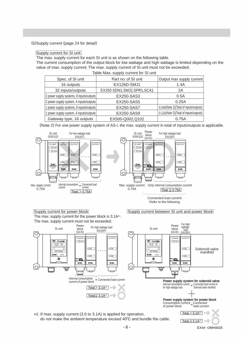
(6)Supply current (page 24 for detail)
Supply current for SI unit The max. supply current for each SI unit is as shown on the following table. The current consumption of the output block for low wattage and high wattage is limited depending on the value of max. supply current. The max. supply current of SI unit must not be exceeded.
(Note 2) For one power supply system of AS-i, the max. supply current in total of inputs/outputs is applicable.
Spec. of SI unit16 outputs
Part no. of SI unitEX126D-SMJ1
Output max supply current1.4A
2 power supply systems, 8 inputs/outputs EX250-SAS3 0.5A2 power supply system, 4 inputs/outputs EX250-SAS5 0.25A
0.75A
1 power supply systems, 8 inputs/outputs EX250-SAS7 0.24A(Note 2)(Total of inputs/outputs)
0.12A(Note 2)(Total of inputs/outputs)
Gateway type, 16 outputs EX500-Q002,Q102
1 power supply system, 4 inputs/outputs EX250-SAS9
32 inputs/outputs EX250-SDN1,SMJ2,SPR1,SCA1 2A
Table Max. supply current for SI unit
For low wattage loadEX9-OET1
SI unitEX500-Q102
COM
PWR
EX500Series
For high wattage loadEX9-OEP1
SI unitEX500-Q102
COM
PWR
EX500Series
Powerblock
EX9-PE1
POWER
PWR
PWRPWR
Max. supply current
Total 0.75A0.75A
Max. supply current Only internal consumption current
Total 0.75A0.75A
Connected load currentRefer to the following
SI unit SI unitPowerblock
EX9-PE1
For highwattage
loadEX9-OEP1
POWER
PWR
PWRPWR
Powerblock
EX9-PE1
POWER
PWR
PWRPWR
Supply current for power block The max. supply current for the power block is 3.1A*1. The max. supply current must not be exceeded.
*1: If max. supply current (3.0 to 3.1A) is applied for operation, do not make the ambient temperature exceed 40 and bundle the cable.
Supply current between SI unit and power block
For high wattage loadEX9-OEP1
Internal consumption + Connected load currentcurrent of power block
Total 3.1A*1
Total 3.1A*1
Total 3.1A
Total 3.1A
Power supply system for solenoid valveInternal consumption current Connected load current offor high wattage load +
Solenoid valve manifold
Power supply system for power blockConsumption current +Connectedof power block load current
Solenoid valvemanifold
Internal consumption + Connected loadcurrent current
- 6 - EX## OMH0025

(7)One power supply system of AS-i
8 inputs/outputs [EX250-SAS7] (Max. 240mA) The max. supply current (240mA) must not be exceeded. For detail, refer to page 25.
SI unitEX250-SAS7
Total 240mA
Total 240mA
Input consumption current
Max. supply current 240mA
Internal consumption current+Connected load current
For lowwattage
loadEX9-OET1
blockEX250-IE1
4 inputs/outputs [EX250-SAS9](MAX 120mA)The max. supply current (120mA) must not beexceeded. For detail, refer to page 25.
SI unitEX250-SAS9
Total 120mA
Total 120mA
Input consumption current
Max. supplycurrent 120mA
Internal consumption current+Connected load current
Outputblock
EX9-OET1block
EX250-IE1
ADDRESS SETTING
SW
ADDR2ADDR1
HOLD
CLEAR
COM-ERR
INAUX -ERRPWR
EX250
1
0
PWR
ADDRESS SETTING
SW
ADDR2ADDR1
HOLD
CLEAR
COM-ERR
INAUX -ERRPWR
EX250
1
0
PWR
(9)The number of connected station
The max. connected station in total of input/output block (excluding SI unit) is 10.
SI unit
Total station 10 (11 or more)
Total station 10
Input block station + Output block station
Outputblock
EX9-OET1
Outputblock
EX9-OET1block
EX250-IE1
ADDRESS SETTING
SW
ADDR2ADDR1
HOLD
CLEAR
COM-ERR
INAUX -ERRPWR
EX250
1
0
PWR
(8)Polarity of output block
If the polarity (output common) of the SI unit is different from the output polarity of connected output block, the normal operation can't be obtained. Be sure to make the output polarity of connected output block consistent with the polarity (output common) of the SI unit.
SI unitPNP output (-COM)
NPN output (+COM)EX9-OET2
SI unitPNP output (-COM)
NPN output (-COM)EX9-OET1
- 7 - EX## OMH0025
- 8 - EX## OMH0025
♦Instructions on handling ∗Installation • Do not drop, hit or apply excessive shock to the product.
Otherwise, it the product can be damaged and have failure or malfunction. • Follow the specified tightening torque.
Excessive tightening torque can break the screws. Refer to “5-6 Installation and Maintenance” for installation.
∗Wiring (including plugging in/out of connector) • Do not bend or apply tensile force to the cables, or apply force by placing a heavy load on them.
Wiring that has bending or tensile stress can cause the cables to break. • Connect wires and cables correctly.
Miswiring can damage the product depending upon condition of the wiring. • Do not connect wires while the power is on.
Otherwise, it can damage the product or I/O devices and cause damage or malfunction. • Do not lay wires or cables in the same wiring route as power cables or high voltage cables.
Otherwise the wires to the product can be interfered with noise or induced surge voltage frompower lines or high voltage lines, resulting in a malfunction. Lay the wires to the product and each I/O device in a wire duct or in a protective tube other thanthose for power lines or high voltage lines.
• Verify the wiring insulation. Poor insulation (interference with other circuits, poor insulation between terminals, etc.) can introduce excess voltage or current to the product or each I/O device causing damage.
• Separate the power lines for the solenoid valves from the power lines for the Input and controlunit. Otherwise, the wires can be contaminated with noise or induced surge voltage, resulting in amalfunction.
• Take proper measurements against noise such as using a noise filter, when the product isincorporated in an equipment or device. Otherwise, interference from noise can cause a malfunction.
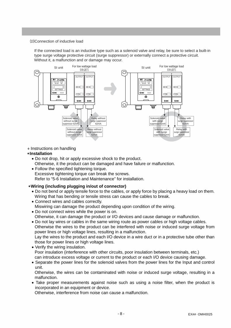
(10)Connection of inductive load
If the connected load is an inductive type such as a solenoid valve and relay, be sure to select a built-in type surge voltage protective circuit (surge suppressor) or externally connect a protective circuit. Without it, a malfunction and or damage may occur.
For low wattage loadEX9-OET1
SI unit
Solenoid valvewithout surge
suppressor 62mA
Relay withoutsurge suppressor
62mA
Solenoid valvewithout surge
suppressor 62mA
Relay withoutsurge suppressor
62mA
For low wattage loadEX9-OET1
SI unit
Solenoid valvewith surge
suppressor 62mA
Relay withsurge suppressor
62mA
Solenoid valvewith surge
suppressor 62mA
Relay withsurge suppressor
62mA

- 9 - EX## OMH0025
∗Environment • Take sufficient measures with shielding, when installing in the following places.
Insufficient measures can cause a malfunction or failure. Verify the effect of the shielding measures after installation of the unit in equipment or devices: (1)A place where noise is generated due to static electricity. (2)A place where electric field strength is high (3)A place where there is irradiation (4)A place near a power line
• Do not use the product near a place where electric surges are generated. Internal circuit elements of the product can deteriorate or become damaged when equipmentgenerating a large surge (electromagnetic lifter, high frequency induction furnace, motor, etc.) islocated near the product. Provide surge suppression, and avoid interference.
• Use the product equipped with a surge absorber when a surge the generating load, such as a relayor solenoid valve, is directly driven. Direct drive of a load generating surge voltage can damage the product.
• Prevent foreign matter such as remnant wires from entering this product. Take proper measures to prevent the foreign matter from entering the product in order to prevent afailure or malfunction.
• Do not expose the product to vibration and impact. Otherwise, it can cause a failure or malfunction.
• Maintain the specified ambient temperature range. Otherwise, it can cause a malfunction. Do not use the product in a place where the temperatureabruptly changes even if it stays within the specified range.
• Do not expose the product to heat radiation from a heat source located nearby. This can cause a malfunction.
∗Maintenance • Before performing maintenance work, make sure to turn of the power supply, stop air supply,
release the residual air in the piping into the atmosphere, and verify that the pneumatic system isopen to the air. Otherwise, an unexpected operation from a system component may occur.
• Perform maintenance and check regularly Otherwise, an unexpected malfunction of the system can occur due to a malfunction of the unit. Refer to “4-3.Installation and Maintenance” the maintenance and checking methods.
• Perform a proper functional check. Stop operation when an abnormality is observed in witch the device does not work properly. Otherwise, an unexpected malfunction of the system component can occur.
• Do not use solvents such as benzene, thinner, etc., to clean the product. It can damage the surface of the body and erase the indication on the body. Use a soft cloth to remove stains. For heavy stains, use a cloth soaked with diluted neutraldetergent and fully squeezed, then wipe the stains again with a dry cloth.
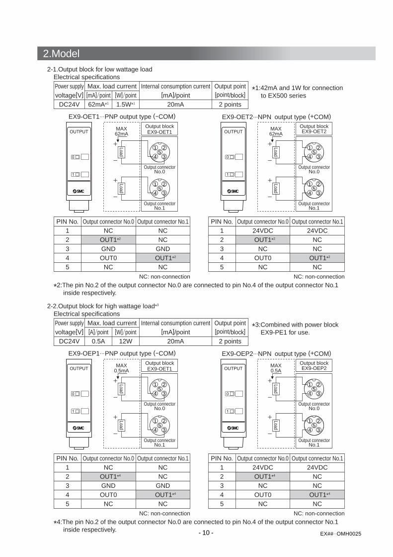
2-1.Output block for low wattage loadElectrical specifications
*2:The pin No.2 of the output connector No.0 are connected to pin No.4 of the output connector No.1 inside respectively.
Power supplyvoltage[V]
Max. load current Internal consumption current Output point[mA]/point [point/block][mA] point [W] point
DC24V 20mA 2 points62mA*1 1.5W*1
1 2
345
1 2
345
Output connectorNo.1
Output blockEX9-OET1
Output connectorNo.0
MAX62mA
PIN No. Output connector No.0 Output connector No.11 NC NC2 OUT1*2 NC3 GND GND4 OUT0 OUT1*2
5 NC NC
1 2
345
1 2
345
Output connectorNo.1
Output blockEX9-OET2
Output connectorNo.0
MAX62mA
PIN No. Output connector No.0 Output connector No.11 24VDC 24VDC2 OUT1*2 NC3 NC NC4 OUT0 OUT1*2
5 NC NC
NC: non-connection NC: non-connection
EX9-OET1 PNP output type (-COM) EX9-OET2 NPN output type (+COM)
*1:42mA and 1W for connection to EX500 series
LoadLoad
LoadLoad
2-2.Output block for high wattage load*3
Electrical specifications
*4:The pin No.2 of the output connector No.0 are connected to pin No.4 of the output connector No.1 inside respectively.
Power supplyvoltage[V]
Max. load current Internal consumption current Output point[mA]/point [point/block][A] point [W] point
DC24V 20mA 2 points0.5A 12W
1 2
345
1 2
345
Output connectorNo.1
Output blockEX9-OET1
Output connectorNo.0
MAX0.5mA
PIN No. Output connector No.0 Output connector No.11 NC NC2 OUT1*4 NC3 GND GND4 OUT0 OUT1*4
5 NC NC
1 2
345
1 2
345
Output connectorNo.1
Output blockEX9-OEP2
Output connectorNo.0
MAX0.5A
PIN No. Output connector No.0 Output connector No.11 24VDC 24VDC2 OUT1*4 NC3 NC NC4 OUT0 OUT1*4
5 NC NC
NC: non-connection NC: non-connection
EX9-OEP1 PNP output type (-COM) EX9-OEP2 NPN output type (+COM)
*3:Combined with power block EX9-PE1 for use.
LoadLoad
LoadLoad
- 10 - EX## OMH0025
2.Model

- 11 - EX OMH0025
2-3.Power block Electrical specification
EX9-PE1
A. Wiring to connect the power block with the power supply
Power supplyvoltage [V]
Max. load current Internal consumption current[A] [mA]/unit
DC24V 3.1A*1 20mA
PIN No. Power supply connector No.0 Power supply connector No.11 - DC24V
- DC0V- -- -- E
2345
DC24V,0V:Output side power supplyE:Earth
-:Unused
PIN No. Power supply connector No.0 Power supply connector No.11 SV 24V_SI DC24V
SV 0V_SI DC0VSW 24V_SI DC24VSW 0V_SI DC0V
E_SI E
2345
SV24V,0V_SI:Output (solenoid valve) side power supplySW24V,0V_SI:Input/control side power supply
E, E_SI:Earth
B.The supply of power from the power block connector to the SI unit
The power supply connector No.0 is available for power supply to SI unit because the power supply connector No.1 is connected to each PIN. Only in case that SI unit is located next to the power block, dedicated accessory cable which is originally prepared for bypass connection can be used.
1 2
345
2 1
435
BUS
PWR
24VDC MAX 3.1A*1Accessory cable
Power blockEX9-PE1
SI unitEX250 series
Power supply connectorNo.1
Power supply connectorNo.0
1 2
345
2 1
435
24VDC MAX 3.1A*1
Power blockEX9-PE1
Power supply connectorNo.1
Power supply connectorNo.0
POWERPWR
PWRPWR
*1: If max. supply current (3.0 to 3.1A) is applied for operation, do not make the ambient temperature exceed 40 and bundle the cable.
- 13 - EX## OMH0025
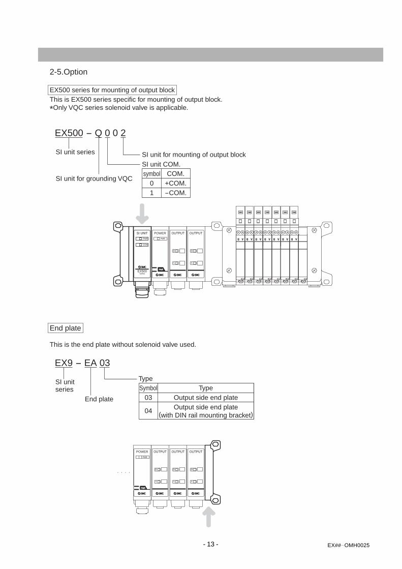
EX500 - Q 0 0 2
SI unit series
SI unit for grounding VQC
SI unit for mounting of output blockSI unit COM.
COM.symbol+COM.0-COM.1
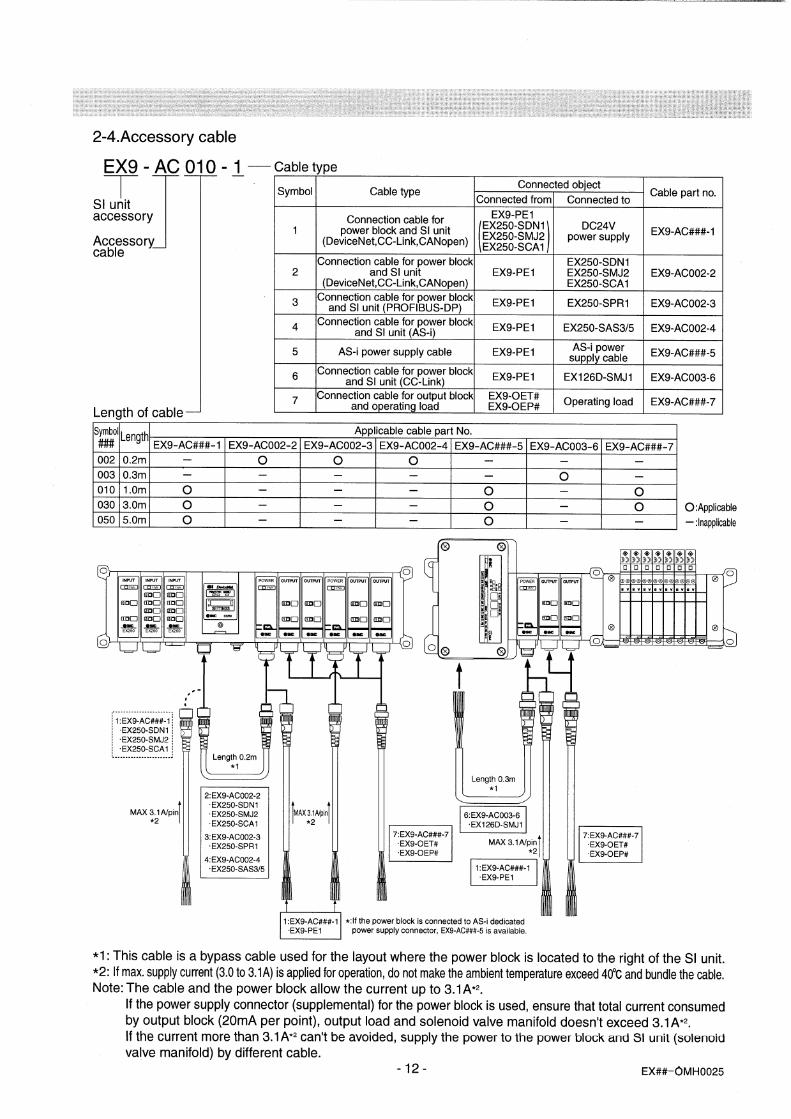
2-5.Option
EX500 series for mounting of output blockThis is EX500 series specific for mounting of output block.
*Only VQC series solenoid valve is applicable.
EX9 - EA 03
SI unitseries
End plate
TypeTypeSymbol
Output side end plate03Output side end plate
(with DIN rail mounting bracket)04
End plate
This is the end plate without solenoid valve used.
COM
PWR
EX500Series
POWERPWR
PWR
POWERPWR
PWR
- 14 - EX## OMH0025
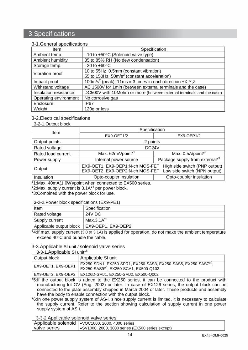
3-1.General specifications Item Specification
Ambient temp. −10 to +50°C (Solenoid valve type) Ambient humidity 35 to 85% RH (No dew condensation) Storage temp. −20 to +60°C
Vibration proof 10 to 55Hz 0.5mm (constant vibration) 55 to 150Hz 50m/s2 (constant acceleration)
Impact proof 100m/s2 (peak), 11ms × 3 times in each direction ±X,Y,Z Withstand voltage AC 1500V for 1min (between external terminals and the case) Insulation resistance DC500V with 10Mohm or more (between external terminals and the case) Operating environment No corrosive gas Enclosure IP67 Weight 120g or less
3-2.Electrical specifications 3-2-1.Output block
Specification Item EX9-OET1/2 EX9-OEP1/2
Output points 2 points Rated voltage DC24V Rated load current Max. 62mA/point*1 Max. 0.5A/point*2 Power supply Internal power source Package supply from external*3
Output EX9-OET1, EX9-OEP1:N-ch MOS-FET High side switch (PNP output) EX9-OET2, EX9-OEP2:N-ch MOS-FET Low side switch (NPN output)
Insulation Opto-coupler insulation Opto-coupler insulation *1:Max. 40mA(1.0W)/point when connected to EX500 series. *2:Max. supply current is 3.1A*4 per power block. *3:Combined with the power block for use. 3-2-2.Power block specifications (EX9-PE1) Item Specification Rated voltage 24V DC Supply current Max.3.1A*4 Applicable output block EX9-OEP1, EX9-OEP2
*4:If max. supply current (3.0 to 3.1A) is applied for operation, do not make the ambient temperature exceed 40°C and bundle the cable.
3-3.Applicable SI unit / solenoid valve series
3-3-1.Applicable SI unit*5 Output block Applicable SI unit
EX9-OET1, EX9-OEP1 EX250-SDN1, EX250-SPR1, EX250-SAS3, EX250-SAS5, EX250-SAS7*6, EX250-SAS9*6, EX250-SCA1, EX500-Q102
EX9-OET2, EX9-OEP2 EX126D-SMJ1, EX250-SMJ2, EX500-Q002 *5:If the output block is added to the EX250 series, it can be connected to the product with
manufacturing lot GV (Aug. 2002) or later. In case of EX126 series, the output block can be connected to the plate assembly shipped in March 2004 or later. These products and assembly have the body to enable connection with the output block.
*6:In one power supply system of AS-i, since supply current is limited, it is necessary to calculate the supply current. Refer to the section showing calculation of supply current in one power supply system of AS-i.
3-3-2.Applicable solenoid valve series
Applicable solenoid valve series
•VQC1000, 2000, 4000 series •SV1000, 2000, 3000 series (EX500 series except)
3.Specifications
4.Wiring and Setting
- 15 - EX## OMH0025
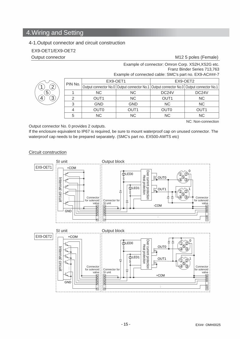
4-1.Output connector and circuit construction
EX9-OET1/EX9-OET2
Output connector M12 5 poles (Female)
Output connector No. 0 provides 2 outputs.If the enclosure equivalent to IP67 is required, be sure to mount waterproof cap on unused connector. Thewaterproof cap needs to be prepared separately. (SMC's part no. EX500-AWTS etc)
Circuit construction
Example of connector: Omron Corp. XS2H,XS2G etc.Franz Binder Series 713,763
Example of connected cable: SMC's part no. EX9-AC###-7
PIN No.Output connector No.0
EX9-OET1 EX9-OET2Output connector No.1
1 NC NC2 OUT1 NC3 GND GND4 OUT0 OUT15 NC NC
Output connector No.0DC24VOUT1
NCOUT0
NC
Output connector No.1DC24V
NCNC
OUT1NC
NC: Non-connection
1 2
345
LED0
LED1
1 2
345
0
11 2
345
+COM
GND
+COM
OUT0
OUT1
1 2
345
-COM
0
11 2
345
+COM
GND
LED0
LED1
OUT0
OUT1
SI unit Output block
SI unit Output block
EX9-OET1
EX9-OET2
Internal circuitInternal circuit
Connector forSI unit
Connectorfor solenoid
valve
Connectorfor solenoid
valve
Connectorfor solenoid
valve
Connector forSI unit
Connectorfor solenoid
valve
Over current protection
Heat protectionO
ver current protectionHeat protection
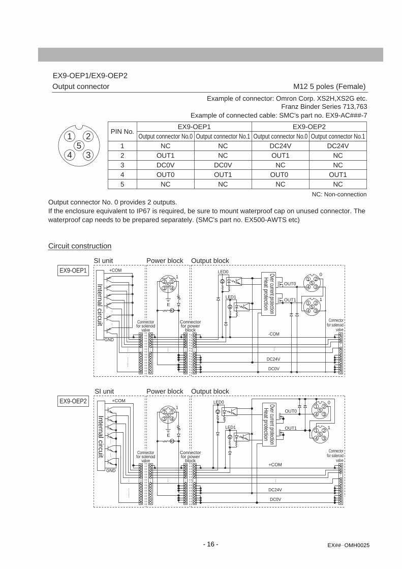
EX9-OEP1/EX9-OEP2
Output connector M12 5 poles (Female)
Output connector No. 0 provides 2 outputs.If the enclosure equivalent to IP67 is required, be sure to mount waterproof cap on unused connector. Thewaterproof cap needs to be prepared separately. (SMC's part no. EX500-AWTS etc)
Circuit construction
Example of connector: Omron Corp. XS2H,XS2G etc.Franz Binder Series 713,763
Example of connected cable: SMC's part no. EX9-AC###-7
PIN No.Output connector No.0
EX9-OEP1 EX9-OEP2Output connector No.1
1 NC NC2 OUT1 NC3 DC0V DC0V4 OUT0 OUT15 NC NC
Output connector No.0DC24VOUT1
NCOUT0
NC
Output connector No.1DC24V
NCNC
OUT1NC
NC: Non-connection
1 2
345
SI unit Power block Output block
SI unit Power block Output block
Internal circuitInternal circuit
Over current protectionHeat protection
Connectorfor solenoid
valve
Connectorfor power
block
Connectorfor solenoid
valve
Over current protectionHeat protection
Connectorfor solenoid
valve
Connectorfor power
block
Connectorfor solenoid
valve
2 1
435
E
1 2
345
0
11 2
345
+COM
GND
DC0V
DC24V
-COM
LED0
LED1
1
OUT0
OUT1
DC0V
1 2
345
0
11 2
345
+COM
LED1
LED0
DC24V
2 1
435
E
1OUT0
OUT1
EX9-OEP1
EX9-OEP2
GND
+COM
- 16 - EX## OMH0025
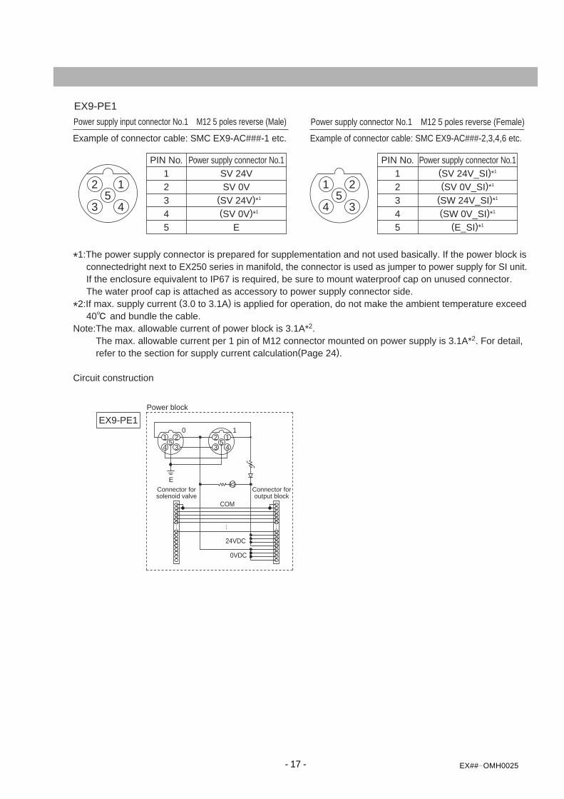
EX9-PE1
Power supply input connector No.1 M12 5 poles reverse (Male)
*1:The power supply connector is prepared for supplementation and not used basically. If the power block is connectedright next to EX250 series in manifold, the connector is used as jumper to power supply for SI unit. If the enclosure equivalent to IP67 is required, be sure to mount waterproof cap on unused connector. The water proof cap is attached as accessory to power supply connector side.
*2:If max. supply current (3.0 to 3.1A) is applied for operation, do not make the ambient temperature exceed 40 and bundle the cable.Note:The max. allowable current of power block is 3.1A*2. The max. allowable current per 1 pin of M12 connector mounted on power supply is 3.1A*2. For detail, refer to the section for supply current calculation(Page 24).
Circuit construction
Example of connector cable: SMC EX9-AC###-1 etc.
Power supply connector No.1 M12 5 poles reverse (Female)
Example of connector cable: SMC EX9-AC###-2,3,4,6 etc.
PIN No. Power supply connector No.1 Power supply connector No.11 SV 24V2 SV 0V3 (SV 24V)*1
4 (SV 0V)*1
5 E
1 2
345
2 1
435
PIN No.1 (SV 24V_SI)*1
2 (SV 0V_SI)*1
3 (SW 24V_SI)*1
4 (SW 0V_SI)*1
5 (E_SI)*1
2 1
435
1
COM
24VDC
0VDC
1 2
345
0
E
Power block
Connector forsolenoid valve
Connector foroutput block
EX9-PE1
- 17 - EX## OMH0025
- 18 - EX## OMH0025
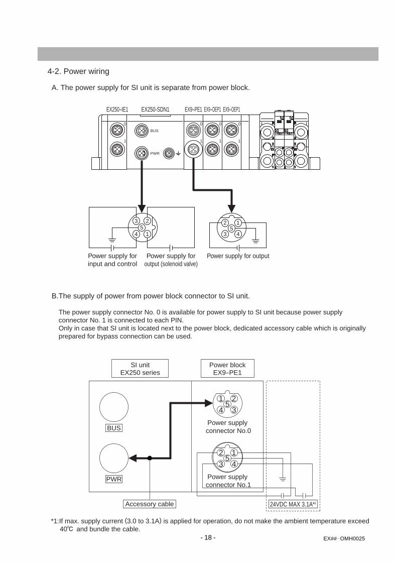
Power supply forinput and control
Power supply foroutput (solenoid valve)
Power supply for output
4-2. Power wiring
A. The power supply for SI unit is separate from power block.
B.The supply of power from power block connector to SI unit.
The power supply connector No. 0 is available for power supply to SI unit because power supply connector No. 1 is connected to each PIN. Only in case that SI unit is located next to the power block, dedicated accessory cable which is originally prepared for bypass connection can be used.
1 2
345
2 1
435
BUS
PWR
24VDC MAX 3.1A*1Accessory cable
Power blockEX9-PE1
SI unitEX250 series
Power supply connector No.1
Power supply connector No.0
1
0
1
0
1
0
1
0BUS
PWR
2
14
35
2 1
435
EX250-IE1 EX250-SDN1 EX9-PE1 EX9-OEP1 EX9-OEP1
*1:If max. supply current (3.0 to 3.1A) is applied for operation, do not make the ambient temperature exceed 40 and bundle the cable.
- 19 - EX## OMH0025
PWR(V) MOD/NETPWR
SETTINGS
1
0
EX250
TM
045
89.8L1L2
155.5
110.8
266
131.8
376.5
152.8
487
173.8
597.5
194.8
6108
215.8
7118.5236.8
8129
257.8
9139.5278.8
10150
299.8
11160.5- - - - - -
12171
13181.5
14192
15202.5
16213
Ln_m
(mm)
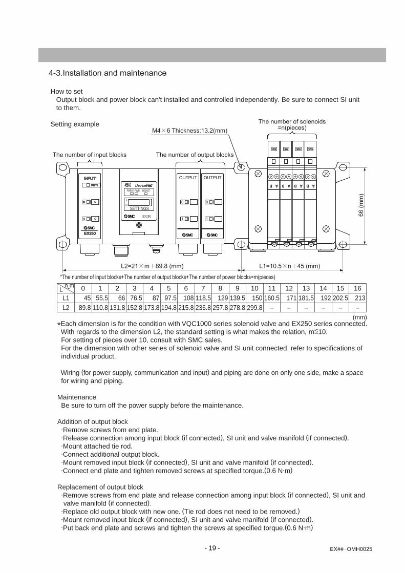
4-3.Installation and maintenance
How to set Output block and power block can't installed and controlled independently. Be sure to connect SI unit to them.
Setting example
*Each dimension is for the condition with VQC1000 series solenoid valve and EX250 series connected. With regards to the dimension L2, the standard setting is what makes the relation, m<10. For setting of pieces over 10, consult with SMC sales. For the dimension with other series of solenoid valve and SI unit connected, refer to specifications of individual product.
Wiring (for power supply, communication and input) and piping are done on only one side, make a space for wiring and piping.
Maintenance Be sure to turn off the power supply before the maintenance.
Addition of output block .Remove screws from end plate. .Release connection among input block (if connected), SI unit and valve manifold (if connected). .Mount attached tie rod. .Connect additional output block. .Mount removed input block (if connected), SI unit and valve manifold (if connected). .Connect end plate and tighten removed screws at specified torque.(0.6 N.m)
Replacement of output block .Remove screws from end plate and release connection among input block (if connected), SI unit and valve manifold (if connected). .Replace old output block with new one. (Tie rod does not need to be removed.) .Mount removed input block (if connected), SI unit and valve manifold (if connected). .Put back end plate and screws and tighten the screws at specified torque.(0.6 N.m)
The number of output blocks
The number of solenoids=n(pieces)
66 (mm)
0
1
OUTPUT
0
1
OUTPUT
*The number of input blocks+The number of output blocks+The number of power blocks=m(pieces)
The number of input blocks
EX250
1
0
=
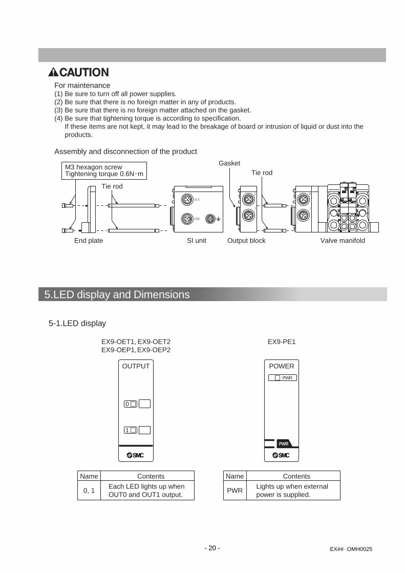
5.LED display and Dimensions
- 20 - EX## OMH0025
0
1
OUTPUT POWER
PWR
PWRPWR
Name
0, 1
Contents
Each LED lights up when OUT0 and OUT1 output.
Name
PWR
Contents
Lights up when external power is supplied.
5-1.LED display
EX9-OET1, EX9-OET2EX9-OEP1,EX9-OEP2
EX9-PE1
For maintenance(1) Be sure to turn off all power supplies.(2) Be sure that there is no foreign matter in any of products.(3) Be sure that there is no foreign matter attached on the gasket.(4) Be sure that tightening torque is according to specification. If these items are not kept, it may lead to the breakage of board or intrusion of liquid or dust into the products.
Assembly and disconnection of the product
End plate SI unit Output block Valve manifold
M3 hexagon screwTightening torque 0.6N m
GasketTie rod
Tie rod
- 21 - EX##-OMH0025
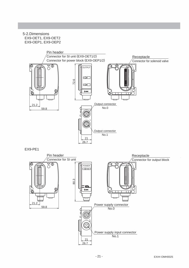
Pin headerConnector for SI unit
21.259.8
ReceptacleConnector for output block
80.3
Pin headerConnector for SI unit (EX9-OET1/2)Connector for power block (EX9-OEP1/2)
21.259.8
ReceptacleConnector for solenoid valve
72.6
1
0
Power supply connectorNo.0
Power supply input connectorNo.1
2126.7
1
0
Output connectorNo.0
Output connectorNo.1
2126.7
0
1
OUTPUT
POWER
PWR
PWRPWR
5-2.Dimensions EX9-OET1, EX9-OET2 EX9-OEP1, EX9-OEP2
EX9-PE1
- 22 - EX##-OMH0025
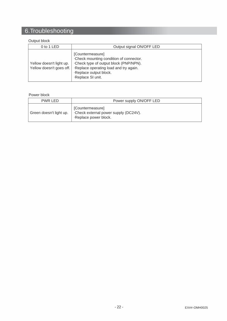
6.Troubleshooting
Output block
0 to 1 LED
Yellow doesn't light up.Yellow doesn't goes off.
[Countermeasure].Check mounting condition of connector..Check type of output block (PNP/NPN)..Replace operating load and try again..Replace output block..Replace SI unit.
Output signal ON/OFF LED
Power block
PWR LED
Green doesn't light up.[Countermeasure].Check external power supply (DC24V)..Replace power block.
Power supply ON/OFF LED
7.Attachment
- 23 - EX## OMH0025
POWERPWR
PWRPWR
POWERPWR
PWRPWR
24VDC,3.1A*1
Power supply forpower block
2
24VDC Power supply forsolenoid valve
1 3
Fan(Max.12W/point)
Lamp(Max.12W/point)
Relay62mA
Power supply for high wattageload (from power block)
Power supply for solenoidvalve (COM) (from SI unit)
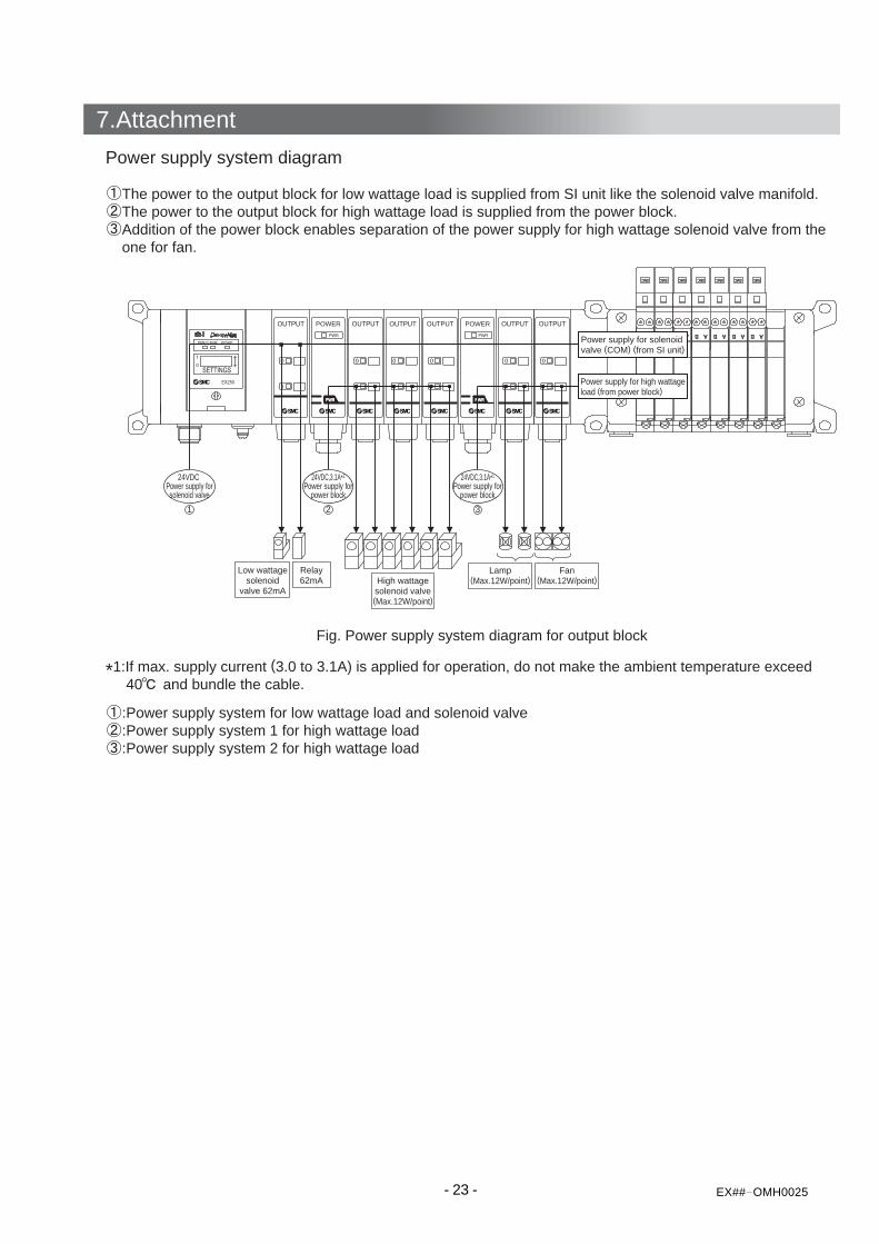
Fig. Power supply system diagram for output block
Power supply system diagram
The power to the output block for low wattage load is supplied from SI unit like the solenoid valve manifold. The power to the output block for high wattage load is supplied from the power block. Addition of the power block enables separation of the power supply for high wattage solenoid valve from the one for fan.
:Power supply system for low wattage load and solenoid valve :Power supply system 1 for high wattage load :Power supply system 2 for high wattage load
24VDC,3.1A*1
Power supply forpower block
Low wattagesolenoid
valve 62mAHigh wattagesolenoid valve(Max.12W/point)
*1:If max. supply current (3.0 to 3.1A) is applied for operation, do not make the ambient temperature exceed 40 and bundle the cable.
- 24 - EX OMH0025
40mA
124mA
InternalconsumprioncurrentLoadconsumprioncurrentInternalconsumprioncurrentLoadconsumprioncurrentInternalconsumprioncurrentLoadconsumprioncurrent
20mA
40mA
1A
40mA
1A
40mA
1A
20mA
40mA
1A
40mA
1A
Power supplysystem 3Total 2.02A
VQC1000 7 station42mAx7=294mA
POWERPWR
PWRPWR
POWERPWR
PWRPWR
24VDC,3.1A*1
Power supply forpower block
21 3
Fan0.5Ax2
Lamp0.5Ax2
High wattagesolenoid valve
0.5Ax6
Low wattagesolenoid
valve 62mA
Relay62mA
Power supply for solenoidvalve (COM) (from SI unit)
Power supply for high wattageload (from power block)
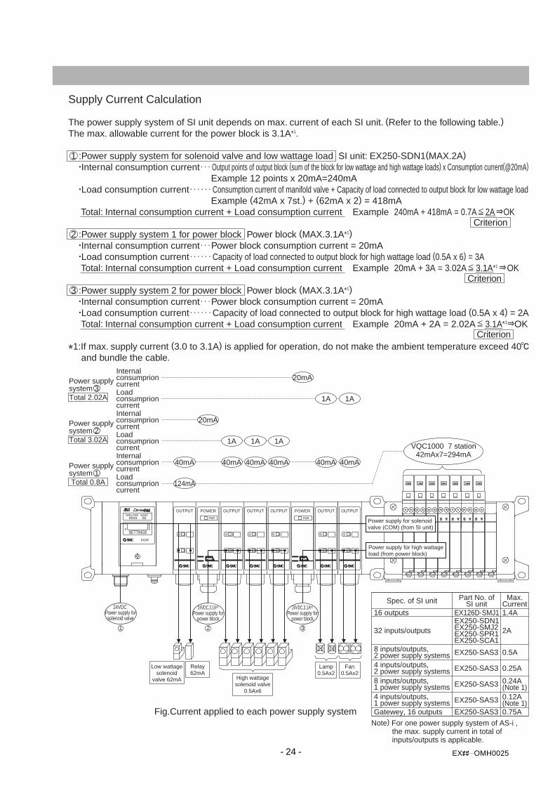
Fig.Current applied to each power supply system
Spec. of SI unit Max.Current
Part No. ofSI unit
1.4A
2A
0.5A
EX250-SDN1EX250-SMJ2EX250-SPR1EX250-SCA1
8 inputs/outputs,2 power supply systems
32 inputs/outputs
16 outputs EX126D-SMJ1
EX250-SAS3
0.25A4 inputs/outputs,2 power supply systems EX250-SAS3
0.24A(Note 1)
8 inputs/outputs,1 power supply systems EX250-SAS3
0.12A(Note 1)
4 inputs/outputs,1 power supply systems EX250-SAS3
0.75AGatewey, 16 outputs EX250-SAS3
Note) For one power supply system of AS-i , the max. supply current in total of inputs/outputs is applicable.
Supply Current Calculation
The power supply system of SI unit depends on max. current of each SI unit. (Refer to the following table.) The max. allowable current for the power block is 3.1A*1.
1 :Power supply system for solenoid valve and low wattage load SI unit: EX250-SDN1(MAX.2A) .Internal consumption current Output points of output block (sum of the block for low wattage and high wattage loads) x Consumption current(@20mA) Example 12 points x 20mA=240mA .Load consumption current Consumption current of manifold valve + Capacity of load connected to output block for low wattage load Example (42mA x 7st.) + (62mA x 2) = 418mA Total: Internal consumption current + Load consumption current Example 240mA + 418mA = 0.7A 2A OK
2 :Power supply system 1 for power block Power block (MAX.3.1A*1) .Internal consumption current Power block consumption current = 20mA .Load consumption current Capacity of load connected to output block for high wattage load (0.5A x 6) = 3A Total: Internal consumption current + Load consumption current Example 20mA + 3A = 3.02A 3.1A*1 OK
3 :Power supply system 2 for power block Power block (MAX.3.1A*1) .Internal consumption current Power block consumption current = 20mA .Load consumption current Capacity of load connected to output block for high wattage load (0.5A x 4) = 2A Total: Internal consumption current + Load consumption current Example 20mA + 2A = 2.02A 3.1A*1 OK
*1:If max. supply current (3.0 to 3.1A) is applied for operation, do not make the ambient temperature exceed 40 and bundle the cable.
Power supplysystem 2Total 3.02A
Power supplysystem 1Total 0.8A
24VDC,3.1A*1
Power supply forpower block
24VDC Power supply forsolenoid valve
Criterion
Criterion
Criterion
- 25 - EX## OMH0025
InternalconsumprioncurrentLoadconsumprioncurrent
10mA
Max. supplycurrent
20mA
40mA
20mA
40mA
40mA
40mATotal consumption current
230.8mA
InternalconsumprioncurrentLoadconsumprioncurrent
Max. supplycurrent
Total consumption current110.8mA
Load40mA
Solenoid valveLoad20mA
Output block(For low wattage load)
Load20mA
SI unitEX250-SAS7
Input blockEX250-IE1
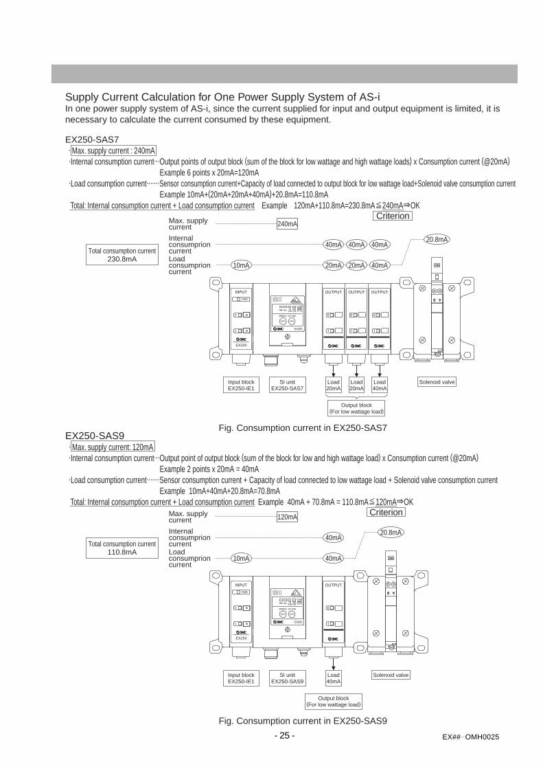
Fig. Consumption current in EX250-SAS7
20.8mA
240mA
EX250
1
0
PWR
EX250-SAS9 . Max. supply current: 120mA .Internal consumption current...Output point of output block (sum of the block for low and high wattage load) x Consumption current (@20mA) Example 2 points x 20mA = 40mA .Load consumption current.......Sensor consumption current + Capacity of load connected to low wattage load + Solenoid valve consumption current Example 10mA+40mA+20.8mA=70.8mA Total: Internal consumption current + Load consumption current Example 40mA + 70.8mA = 110.8mA 120mA OK
Supply Current Calculation for One Power Supply System of AS-iIn one power supply system of AS-i, since the current supplied for input and output equipment is limited, it isnecessary to calculate the current consumed by these equipment.
EX250-SAS7 . Max. supply current : 240mA .Internal consumption current...Output points of output block (sum of the block for low wattage and high wattage loads) x Consumption current (@20mA) Example 6 points x 20mA=120mA .Load consumption current.......Sensor consumption current+Capacity of load connected to output block for low wattage load+Solenoid valve consumption current Example 10mA+(20mA+20mA+40mA)+20.8mA=110.8mA Total: Internal consumption current + Load consumption current Example 120mA+110.8mA=230.8mA 240mA OK
10mA 40mA
40mA
Load40mA
Solenoid valve
Output block(For low wattage load)
SI unitEX250-SAS9
Input blockEX250-IE1
Fig. Consumption current in EX250-SAS9
20.8mA
120mA
EX250
1
0
PWR
Criterion
Criterion
- 26 - EX## OMH0025
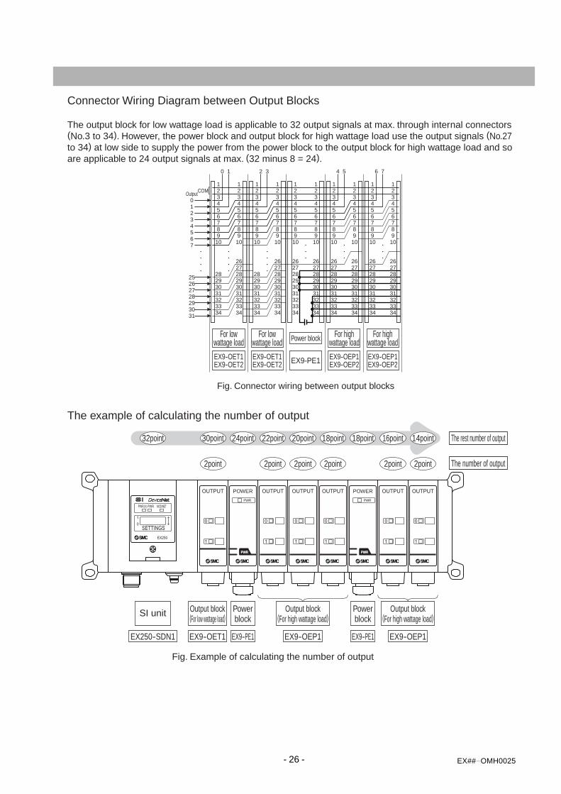
Connector Wiring Diagram between Output Blocks
The output block for low wattage load is applicable to 32 output signals at max. through internal connectors(No.3 to 34). However, the power block and output block for high wattage load use the output signals (No.27to 34) at low side to supply the power from the power block to the output block for high wattage load and soare applicable to 24 output signals at max. (32 minus 8 = 24).
The example of calculating the number of output
21
2 30 1
3452
34567
6789
10
21
345678910
21
3456789
10
4 5 6 7
10
OutputCOM
282926
2728293031
3031323334
262728293031323334
28293031323334
21
3456789
10
21
3456789
10
262728293031323334
262728293031323334
21
3456789
10
21
3456789
10
262728293031323334
262728293031323334
21
3456789
10
21
3456789
10
262728293031323334
262728293031323334
21
3456789
10
262728293031323334
25
For lowwattage load
For lowwattage load
For highwattage load
For highwattage loadPower block
EX9-PE1
2point
30point32point 24point
2point
22point
2point
20point
2point
18point 18point
2point
16point
2point
14point
POWER
PWR
PWR
POWER
PWR
PWR
The rest number of output
The number of output
SI unit
EX250-SDN1
Output block(For low wattage load)
EX9-OET1
Output block(For high wattage load)
EX9-OEP1
Output block(For high wattage load)
EX9-OEP1
Powerblock
EX9-PE1
Powerblock
EX9-PE1
Fig. Connector wiring between output blocks
Fig. Example of calculating the number of output
EX9-OET1EX9-OET2
EX9-OET1EX9-OET2
EX9-OEP1EX9-OEP2
EX9-OEP1EX9-OEP2


![Sony Hcd-ex6 Ex6t Ex8 Ex8t Ex9 Ex9t Ver-1.1 Sm [ET]](https://static.documents.pub/doc/80x56/54507aadb1af9f19098b4dbb/sony-hcd-ex6-ex6t-ex8-ex8t-ex9-ex9t-ver-11-sm-et.jpg)


